EP3667629A1 - Apparatus and method for testing a glass break detection system - Google Patents
Apparatus and method for testing a glass break detection system Download PDFInfo
- Publication number
- EP3667629A1 EP3667629A1 EP18461642.3A EP18461642A EP3667629A1 EP 3667629 A1 EP3667629 A1 EP 3667629A1 EP 18461642 A EP18461642 A EP 18461642A EP 3667629 A1 EP3667629 A1 EP 3667629A1
- Authority
- EP
- European Patent Office
- Prior art keywords
- glass break
- speaker
- remote device
- sensor
- break detection
- Prior art date
- Legal status (The legal status is an assumption and is not a legal conclusion. Google has not performed a legal analysis and makes no representation as to the accuracy of the status listed.)
- Granted
Links
Images
Classifications
-
- G—PHYSICS
- G08—SIGNALLING
- G08B—SIGNALLING SYSTEMS, e.g. PERSONAL CALLING SYSTEMS; ORDER TELEGRAPHS; ALARM SYSTEMS
- G08B13/00—Burglar, theft or intruder alarms
- G08B13/02—Mechanical actuation
- G08B13/04—Mechanical actuation by breaking of glass
-
- G—PHYSICS
- G08—SIGNALLING
- G08B—SIGNALLING SYSTEMS, e.g. PERSONAL CALLING SYSTEMS; ORDER TELEGRAPHS; ALARM SYSTEMS
- G08B29/00—Checking or monitoring of signalling or alarm systems; Prevention or correction of operating errors, e.g. preventing unauthorised operation
- G08B29/12—Checking intermittently signalling or alarm systems
- G08B29/14—Checking intermittently signalling or alarm systems checking the detection circuits
Definitions
- the present disclosure relates generally systems and methods for testing a glass break detection system, and more specifically for a system and method for remotely testing a glass break detection system.
- a simple glass break detections system includes a microphone positioned within a room. The microphone is communicatively coupled to a main panel. Sounds picked up by the microphone are compared against one or more stored sound patterns to determine if the detected sound pattern is consistent with a glass break sound pattern. When the detected sounds are consistent with a known glass break pattern, a glass break is detected and the security system reacts accordingly.
- a glass break detection testing system includes a speaker communicatively coupled to a remote device, the remote device being configured to transmit a recorded sound file to the speaker thereby causing the speaker to emit the transmitted sound file.
- the remote device is exterior to a room including the speaker, and wherein the remote device is connected to the speaker via one of a local wireless communication protocol and a hardwired network.
- the speaker is temporarily connected to a window via a suction cup.
- the speaker is permanently affixed proximate a window.
- the remote device is connected to one of a sensor within a room and a security system connected to the sensor within the room, such that the remote device is capable of monitoring a reaction of the one of the sensor and the security system.
- the remote device is connected to the security system through a cloud based network.
- the remote device is directly connected to the sensor via one of a local wireless connection and a hardwires connection.
- the senor includes a microphone.
- the speaker includes a processor and a memory, and wherein the memory is configured to receive and retain at least one recorded sound filed from the remote device.
- the remote device includes a memory storing instructions configured to cause the remote device to provide a sound file to the speaker, and monitor a corresponding one of a security system and a sensor, thereby determining if a functionality of the corresponding one of the security system and the sensor.
- An exemplary method for testing a glass break detection system includes transmitting a sound file from a first device to a speaker disposed within a room, playing the sound file using the speaker, comparing a sound detected by a sensor within the room with a predetermined set of glass break patterns, and determining that the glass break detection system is functional when the comparison indicates a match.
- transmitting the sound from the first device to the speaker includes selecting at least one glass break recording from a set of glass break recordings using a remote device exterior to the room, and transmitting the selected at least one glass break recording to the speaker.
- the set of glass break recordings is stored on the remote device.
- the set of glass break recordings is stored on one of a second device and a cloud network connected to the remote device and the speaker.
- Another example of any of the above described methods for testing a glass break detection system further includes updating the set of glass break recordings by providing at least one new glass break recording to the one of the second device and the cloud network.
- any of the above described methods for testing a glass break detection system comparing the sound detected by the sensor within the room with the predetermined set of glass break patterns is performed by a main security system, and wherein the first device is communicatively coupled to the main security system.
- any of the above described methods for testing a glass break detection system comparing the sound detected by the sensor within the room with the predetermined set of glass break patterns is performed by the first device, and wherein the first device is communicatively coupled to the sensor.
- Some alternate state of the art intrusion detection systems and/or glass break detection testers require that the tester be positioned immediately adjacent to, or near, the microphone sensor. Such systems do not reflect the audio characteristics and acoustics of the room layout, and of any physical barriers such as furniture, walls, partial walls, decorations, etc. that may be positioned between the window and the sensor and may impact the ability of the sensor to detect glass breaking.
- glass break testers Further limiting current state of the art glass break testers is the inclusion of a limited number of example glass break sounds within the tester, relative to the variety of available glass types.
- a typical tester will only have one to two breaking glass recordings present, but substantially more glass types are on the market and can be used, with each type having a unique sound characteristic when it breaks.
- the inadequacy of existing glass break testers in this area is exacerbated.
- Figure 1 schematically illustrates a room 10 including a glass break detection system with remote testing capabilities.
- the room 10 includes a window 20 with a remote controlled speaker 22 attached to the window.
- the remote controlled speaker 22 can be permanently attached via a fixture to the window frame, or temporarily attached to the window 20 via any form of temporary mechanical connection.
- the remote controlled speaker can include a memory and a processor, with the memory being configured to receive and retain at least one prerecorded sound file and includes instructions for playing the prerecorded sound file using the processor and the speaker 22.
- the temporary attachment can include a suction cup configured to attach the remote speaker 22 to a smooth surface, such as window glass.
- a suction cup configured to attach the remote speaker 22 to a smooth surface, such as window glass.
- the stationary elements 30 Disposed about the room 10 are multiple stationary elements 30, such as furniture, decorations, entertainment systems and the like.
- the stationary elements 30 are large enough to affect the acoustical character of the room, and generally remain in the same approximate position after all individuals have left the room 10.
- a sensor 40 such as a microphone, is disposed in one corner of the room 10, remote from the window 20.
- the location of the sensor 40 can vary, and can be determined based on easily concealable locations, a position minimizing a distance to each of multiple windows 20, or based on any other numbers of factors including ease of wiring.
- the sensor 40 is connected via a communication line 42 to a main security panel 60.
- the main security panel 60 is a fully self-contained security system including all computer programing required to operate the security systems.
- the panel 60 is connected to a network 70, such as a cloud network through the internet, and all or some of the security operations are managed through the cloud according to any known security system protocol.
- the mobile device 50 includes computer software configured to use a local wireless connection 52 to communicate with the speaker 22 from outside the room 10 through one or more walls, ceilings or floors.
- the local wireless connection 52 can be any form or protocol of local wireless connection 52.
- the mobile device 50 can include a direct communicative connection 54 to the sensor 40. Inclusion of the direct connection 54 can allow the mobile device 50 to fully perform the test, including comparing the sound received at the sensor 40 to the sound played by the speaker 22 using the mobile device 50, without requiring a connection to the main panel 60, or to the network 70.
- the testing system incorporated in the room 10 can allow for operation of remote tests through the network 70.
- the mobile device 50 can be replaced with a desktop, or other computing system, located at an offsite location.
- an operator of the device 50 can, from the remote location, command the test occur.
- such a test may be desired after the stationary elements 30 within the room have been rearranged, after new stationary elements 30 have been added, previously present stationary elements 30 have been removed, the window 20 has been updated with a different style, or type of glass, or any other change has occurred that could affect the acoustics of the room 10.
- figure 2 schematically illustrates an exemplary process for operating a glass break test using the system incorporated in the room 10 of Figure 1 .
- an operator loads a testing application on the mobile device 50, or other system, in a "Load Test Software" step 110.
- the mobile device 50 ensures a communicative connection with the sensor 40, either via the direct connection 54, or indirectly through the network 70 and the main panel 60. Once the connection is verified, and operation of the sensor 40 is confirmed, the mobile device 50 enables the operator to begin the test.
- the operator selects one or more glass break sound from a list of glass break sounds contained within the mobile device 50, or in the security system connected to the mobile device 50 via the network 70, in a "Select Glass Break Sound” step 120.
- the file for the glass break sound is transmitted to the speaker 22 in a "Transmit Sound File” step 130.
- substantially larger numbers of available glass breaking sounds can be used with the testing system.
- the glass break sounds can be remotely updated to reflect new glass types, new window configurations, or any similar changes in the window 20 structure that could alter the sound characteristics of glass breaking.
- the speaker 22 plays the glass break sound in a "Play Transmitted Sound” step 140. Simultaneous with, and shortly following, the playing of the transmitted sound the system monitors the sensor 40 and the main security panel 60 to determine if a glass break detection occurs in a "Monitor Sensor" step 150, without requiring manual changes to the tester.
- the operator If the system detects glass breaking in response to the speaker 22 playing the glass break sound, the operator knows that the system is calibrated correctly and is functional. If no glass break detection occurs, then the operator can evaluate the conditions, repeat the test, or otherwise troubleshoot the system.
- the glass break detection system can be remotely tested, without requiring any modification to the sensors, or physical structures of the security system. Further, the utilization of network stored files and software applications allows for the testing to be updated to accommodate new technologies, new sensors and the like.
- the testing conditions e.g. empty room, with immobile stationary elements
- the testing conditions can be repeatable and can accurately reflect the conditions of the room when a glass break detection is necessary.
- the ability of the speaker 22 to be connected directly to the network 70 allows for substantially remote operation and upgrade of the testing system.
Landscapes
- Physics & Mathematics (AREA)
- General Physics & Mathematics (AREA)
- Engineering & Computer Science (AREA)
- Computer Security & Cryptography (AREA)
- Alarm Systems (AREA)
Abstract
Description
- The present disclosure relates generally systems and methods for testing a glass break detection system, and more specifically for a system and method for remotely testing a glass break detection system.
- Security systems, such as home invasion detection systems, building security systems, and the like, frequently include glass break detection systems as some or all of their intrusion detection. A simple glass break detections system includes a microphone positioned within a room. The microphone is communicatively coupled to a main panel. Sounds picked up by the microphone are compared against one or more stored sound patterns to determine if the detected sound pattern is consistent with a glass break sound pattern. When the detected sounds are consistent with a known glass break pattern, a glass break is detected and the security system reacts accordingly.
- In order to test whether a glass break detection system is functional, current state of the art testing schemes utilize a maintenance technician standing in the room with a testing device. The testing device plays back a limited number of prerecorded glass break sounds, and the main panel is monitored to determine if a glass break sound is detected.
- In one exemplary embodiment a glass break detection testing system includes a speaker communicatively coupled to a remote device, the remote device being configured to transmit a recorded sound file to the speaker thereby causing the speaker to emit the transmitted sound file.
- In another example of the above described glass break detection system the remote device is exterior to a room including the speaker, and wherein the remote device is connected to the speaker via one of a local wireless communication protocol and a hardwired network.
- In another example of any of the above described glass break detection systems the speaker is temporarily connected to a window via a suction cup.
- In another example of any of the above described glass break detection systems the speaker is permanently affixed proximate a window.
- In another example of any of the above described glass break detection systems the remote device is connected to one of a sensor within a room and a security system connected to the sensor within the room, such that the remote device is capable of monitoring a reaction of the one of the sensor and the security system.
- In another example of any of the above described glass break detection systems the remote device is connected to the security system through a cloud based network.
- In another example of any of the above described glass break detection systems the remote device is directly connected to the sensor via one of a local wireless connection and a hardwires connection.
- In another example of any of the above described glass break detection systems the sensor includes a microphone.
- In another example of any of the above described glass break detection systems the speaker includes a processor and a memory, and wherein the memory is configured to receive and retain at least one recorded sound filed from the remote device.
- In another example of any of the above described glass break detection systems the remote device includes a memory storing instructions configured to cause the remote device to provide a sound file to the speaker, and monitor a corresponding one of a security system and a sensor, thereby determining if a functionality of the corresponding one of the security system and the sensor.
- An exemplary method for testing a glass break detection system includes transmitting a sound file from a first device to a speaker disposed within a room, playing the sound file using the speaker, comparing a sound detected by a sensor within the room with a predetermined set of glass break patterns, and determining that the glass break detection system is functional when the comparison indicates a match.
- In another example of the above described method for testing a glass break detection system transmitting the sound from the first device to the speaker includes selecting at least one glass break recording from a set of glass break recordings using a remote device exterior to the room, and transmitting the selected at least one glass break recording to the speaker.
- In another example of any of the above described methods for testing a glass break detection system the set of glass break recordings is stored on the remote device.
- In another example of any of the above described methods for testing a glass break detection system the set of glass break recordings is stored on one of a second device and a cloud network connected to the remote device and the speaker.
- Another example of any of the above described methods for testing a glass break detection system further includes updating the set of glass break recordings by providing at least one new glass break recording to the one of the second device and the cloud network.
- In another example of any of the above described methods for testing a glass break detection system comparing the sound detected by the sensor within the room with the predetermined set of glass break patterns is performed by a main security system, and wherein the first device is communicatively coupled to the main security system.
- In another example of any of the above described methods for testing a glass break detection system comparing the sound detected by the sensor within the room with the predetermined set of glass break patterns is performed by the first device, and wherein the first device is communicatively coupled to the sensor.
- These and other features of the present invention can be best understood from the following specification and drawings, the following of which is a brief description.
-
-
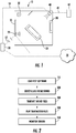
Figure 1 illustrates an exemplary glass break detection system within a room. -
Figure 2 schematically illustrates a method for operating the remote glass break detection test using the system ofFigure 1 . - Current state of the art glass break testers are operated manually within a room or zone being tested by the operator holding a tester in a predetermined position and playing one or more prerecorded glass break sounds. The tester can be held by the window(s) in the room, but the positioning of the tester and/or the operator can influence the test, and the operator cannot determine if the test is successful without leaving and reentering the room. As a result, the tests are not repeatable with the exact same conditions.
- Some alternate state of the art intrusion detection systems and/or glass break detection testers require that the tester be positioned immediately adjacent to, or near, the microphone sensor. Such systems do not reflect the audio characteristics and acoustics of the room layout, and of any physical barriers such as furniture, walls, partial walls, decorations, etc. that may be positioned between the window and the sensor and may impact the ability of the sensor to detect glass breaking.
- Further limiting current state of the art glass break testers is the inclusion of a limited number of example glass break sounds within the tester, relative to the variety of available glass types. By way of example, a typical tester will only have one to two breaking glass recordings present, but substantially more glass types are on the market and can be used, with each type having a unique sound characteristic when it breaks. Further, as new glass types and configurations are developed, the inadequacy of existing glass break testers in this area is exacerbated.
-
Figure 1 schematically illustrates aroom 10 including a glass break detection system with remote testing capabilities. Theroom 10 includes awindow 20 with a remote controlledspeaker 22 attached to the window. The remote controlledspeaker 22 can be permanently attached via a fixture to the window frame, or temporarily attached to thewindow 20 via any form of temporary mechanical connection. The remote controlled speaker can include a memory and a processor, with the memory being configured to receive and retain at least one prerecorded sound file and includes instructions for playing the prerecorded sound file using the processor and thespeaker 22. - In one example, the temporary attachment can include a suction cup configured to attach the
remote speaker 22 to a smooth surface, such as window glass. Disposed about theroom 10 are multiplestationary elements 30, such as furniture, decorations, entertainment systems and the like. Thestationary elements 30 are large enough to affect the acoustical character of the room, and generally remain in the same approximate position after all individuals have left theroom 10. - A
sensor 40, such as a microphone, is disposed in one corner of theroom 10, remote from thewindow 20. The location of thesensor 40 can vary, and can be determined based on easily concealable locations, a position minimizing a distance to each ofmultiple windows 20, or based on any other numbers of factors including ease of wiring. - The
sensor 40 is connected via acommunication line 42 to amain security panel 60. In some examples themain security panel 60 is a fully self-contained security system including all computer programing required to operate the security systems. In alternative examples, thepanel 60 is connected to anetwork 70, such as a cloud network through the internet, and all or some of the security operations are managed through the cloud according to any known security system protocol. - Also connected to the
network 70 is amobile device 50, or other remote testing apparatus. Themobile device 50 includes computer software configured to use a localwireless connection 52 to communicate with thespeaker 22 from outside theroom 10 through one or more walls, ceilings or floors. The localwireless connection 52 can be any form or protocol of localwireless connection 52. By connecting themobile device 50 to thespeaker 22 using the local wireless connection, a technician can operate thespeaker 22 portion of the testing system while the room is empty of all people, including the technician. This allows thesensor 40 to be tested in actual conditions that would be present were an intruder to break the glass and try entering, as well as allowing the specific testing conditions of any given test to be repeatable. - In some examples, the
mobile device 50 can include a directcommunicative connection 54 to thesensor 40. Inclusion of thedirect connection 54 can allow themobile device 50 to fully perform the test, including comparing the sound received at thesensor 40 to the sound played by thespeaker 22 using themobile device 50, without requiring a connection to themain panel 60, or to thenetwork 70. - In yet further examples, such as those where the
speaker 22 is permanently mounted in a single position and connected to thenetwork 70, the testing system incorporated in theroom 10 can allow for operation of remote tests through thenetwork 70. In such an examples, themobile device 50 can be replaced with a desktop, or other computing system, located at an offsite location. When a user requests confirmation that the glass break detector (sensor 40) is functional, an operator of thedevice 50 can, from the remote location, command the test occur. - By way of example, such a test may be desired after the
stationary elements 30 within the room have been rearranged, after newstationary elements 30 have been added, previously presentstationary elements 30 have been removed, thewindow 20 has been updated with a different style, or type of glass, or any other change has occurred that could affect the acoustics of theroom 10. - With continued reference to
Figure 1 figure 2 schematically illustrates an exemplary process for operating a glass break test using the system incorporated in theroom 10 ofFigure 1 . - Initially, an operator loads a testing application on the
mobile device 50, or other system, in a "Load Test Software"step 110. As part of loading the test software, themobile device 50 ensures a communicative connection with thesensor 40, either via thedirect connection 54, or indirectly through thenetwork 70 and themain panel 60. Once the connection is verified, and operation of thesensor 40 is confirmed, themobile device 50 enables the operator to begin the test. - During the initial stage of the test, the operator selects one or more glass break sound from a list of glass break sounds contained within the
mobile device 50, or in the security system connected to themobile device 50 via thenetwork 70, in a "Select Glass Break Sound"step 120. Once selected, the file for the glass break sound is transmitted to thespeaker 22 in a "Transmit Sound File"step 130. By storing the sound files either on themobile device 50 or in the cloud connected to thenetwork 70, and transmitting the sound to thespeaker 22, substantially larger numbers of available glass breaking sounds can be used with the testing system. Further, by hosting the sounds in the cloud and connecting to the cloud through thenetwork 70, the glass break sounds can be remotely updated to reflect new glass types, new window configurations, or any similar changes in thewindow 20 structure that could alter the sound characteristics of glass breaking. - Once the sound file has been transmitted to the
speaker 22, thespeaker 22 plays the glass break sound in a "Play Transmitted Sound"step 140. Simultaneous with, and shortly following, the playing of the transmitted sound the system monitors thesensor 40 and themain security panel 60 to determine if a glass break detection occurs in a "Monitor Sensor" step 150, without requiring manual changes to the tester. - If the system detects glass breaking in response to the
speaker 22 playing the glass break sound, the operator knows that the system is calibrated correctly and is functional. If no glass break detection occurs, then the operator can evaluate the conditions, repeat the test, or otherwise troubleshoot the system. - By utilizing the system and methods described at
Figures 1 and 2 , the glass break detection system can be remotely tested, without requiring any modification to the sensors, or physical structures of the security system. Further, the utilization of network stored files and software applications allows for the testing to be updated to accommodate new technologies, new sensors and the like. The testing conditions (e.g. empty room, with immobile stationary elements) can be repeatable and can accurately reflect the conditions of the room when a glass break detection is necessary. In addition to the above, the ability of thespeaker 22 to be connected directly to thenetwork 70 allows for substantially remote operation and upgrade of the testing system. - It is further understood that any of the above described concepts can be used alone or in combination with any or all of the other above described concepts. Although an embodiment of this invention has been disclosed, a worker of ordinary skill in this art would recognize that certain modifications would come within the scope of this invention. For that reason, the following claims should be studied to determine the true scope and content of this invention.
Claims (15)
- A glass break detection testing system comprising:a speaker communicatively coupled to a remote device, the remote device being configured to transmit a recorded sound file to the speaker thereby causing the speaker to emit the transmitted sound file.
- The glass break detection testing system of claim 1, wherein the remote device is exterior to a room including the speaker, and wherein the remote device is connected to the speaker via one of a local wireless communication protocol and a hardwired network.
- The glass break detection system of claim 1 or 2, wherein the speaker is temporarily connected to a window via a suction cup.
- The glass break detection system of any of the preceding claims, wherein the speaker is permanently affixed proximate a window.
- The glass break detection system of any of the preceding claims, wherein the remote device is connected to one of a sensor within a room and a security system connected to the sensor within the room, such that the remote device is capable of monitoring a reaction of the one of the sensor and the security system.
- The glass break detection system of claim 5, wherein the remote device is connected to the security system through a cloud based network.
- The glass break detection system of claim 5 or 6, wherein the remote device is directly connected to the sensor via one of a local wireless connection and a hardwires connection.
- The glass break detection system of any of claims 5 to 7, wherein the sensor includes a microphone.
- The glass break detection system of any of the preceding claims, wherein the speaker includes a processor and a memory, and wherein the memory is configured to receive and retain at least one recorded sound filed from the remote device.
- The glass break detection system of any of the preceding claims, wherein the remote device includes a memory storing instructions configured to cause the remote device to provide a sound file to the speaker, and monitor a corresponding one of a security system and a sensor, thereby determining if a functionality of the corresponding one of the security system and the sensor.
- A method for testing a glass break detection system comprising:transmitting a sound file from a first device to a speaker disposed within a room;playing the sound file using the speaker;comparing a sound detected by a sensor within the room with a predetermined set of glass break patterns; anddetermining that the glass break detection system is functional when the comparison indicates a match.
- The method of claim 11, wherein transmitting the sound from the first device to the speaker includes selecting at least one glass break recording from a set of glass break recordings using a remote device exterior to the room, and transmitting the selected at least one glass break recording to the speaker.
- The method of claim 12, wherein the set of glass break recordings is stored on the remote device.
- The method of claim 12,
wherein the set of glass break recordings is stored on one of a second device and a cloud network connected to the remote device and the speaker; and
wherein the method particularly further comprises updating the set of glass break recordings by providing at least one new glass break recording to the one of the second device and the cloud network. - The method of any of claims 11 to 14,
wherein comparing the sound detected by the sensor within the room with the predetermined set of glass break patterns is performed by a main security system, and wherein the first device is communicatively coupled to the main security system; and/or
wherein comparing the sound detected by the sensor within the room with the predetermined set of glass break patterns is performed by the first device, and wherein the first device is communicatively coupled to the sensor.
Priority Applications (3)
| Application Number | Priority Date | Filing Date | Title |
|---|---|---|---|
| EP18461642.3A EP3667629B1 (en) | 2018-12-14 | 2018-12-14 | Apparatus and method for testing a glass break detection system |
| US17/252,763 US11302158B2 (en) | 2018-12-14 | 2019-12-13 | Apparatus and method for testing a glass break detection system |
| PCT/US2019/066205 WO2020123927A1 (en) | 2018-12-14 | 2019-12-13 | Apparatus and method for testing a glass break detection system |
Applications Claiming Priority (1)
| Application Number | Priority Date | Filing Date | Title |
|---|---|---|---|
| EP18461642.3A EP3667629B1 (en) | 2018-12-14 | 2018-12-14 | Apparatus and method for testing a glass break detection system |
Publications (2)
| Publication Number | Publication Date |
|---|---|
| EP3667629A1 true EP3667629A1 (en) | 2020-06-17 |
| EP3667629B1 EP3667629B1 (en) | 2022-12-07 |
Family
ID=64949131
Family Applications (1)
| Application Number | Title | Priority Date | Filing Date |
|---|---|---|---|
| EP18461642.3A Active EP3667629B1 (en) | 2018-12-14 | 2018-12-14 | Apparatus and method for testing a glass break detection system |
Country Status (3)
| Country | Link |
|---|---|
| US (1) | US11302158B2 (en) |
| EP (1) | EP3667629B1 (en) |
| WO (1) | WO2020123927A1 (en) |
Families Citing this family (1)
| Publication number | Priority date | Publication date | Assignee | Title |
|---|---|---|---|---|
| US12050199B1 (en) * | 2023-12-21 | 2024-07-30 | The Adt Security Corporation | Glass break detection using ultrasonic signal(s) |
Citations (3)
| Publication number | Priority date | Publication date | Assignee | Title |
|---|---|---|---|---|
| US5164703A (en) * | 1991-05-02 | 1992-11-17 | C & K Systems, Inc. | Audio intrusion detection system |
| US20130076506A1 (en) * | 2011-09-23 | 2013-03-28 | Honeywell International Inc. | System and Method for Testing and Calibrating Audio Detector and Other Sensing and Communications Devices |
| US20130170323A1 (en) * | 2012-01-03 | 2013-07-04 | Richard Alan Smith | Method and System for Audio Detector Mode Activation |
Family Cites Families (17)
| Publication number | Priority date | Publication date | Assignee | Title |
|---|---|---|---|---|
| ATE321402T1 (en) | 2000-05-17 | 2006-04-15 | Symstream Technology Holdings | OPD (OCTAVE PULSE DATA) - METHOD AND APPARATUS |
| WO2001093220A1 (en) | 2000-05-26 | 2001-12-06 | Royal Thoughts, L.L.C. | Modular communication and control system and method |
| CA2689757A1 (en) | 2007-07-18 | 2009-01-18 | Steven C. Kays | Adaptive electronic design |
| US8269627B2 (en) | 2007-11-30 | 2012-09-18 | Andersen Corporation | Status monitoring system for a fenestration unit |
| CA2762101C (en) | 2009-05-18 | 2017-07-04 | Alarm.Com Incorporated | Moving asset location tracking |
| US20120092163A1 (en) * | 2010-04-14 | 2012-04-19 | Hart Joseph N | Intruder detection and interdiction system and methods for using the same |
| US20140361896A1 (en) * | 2013-06-05 | 2014-12-11 | Keith Alan Sibley | Intrusion Detection System and Method thereof |
| WO2015058133A1 (en) | 2013-10-17 | 2015-04-23 | Adt Us Holdings, Inc. | Portable system for managing events |
| US9903606B2 (en) | 2014-04-29 | 2018-02-27 | Vivint, Inc. | Controlling parameters in a building |
| CA2946891A1 (en) | 2014-05-07 | 2015-11-12 | Vivint, Inc. | Controlling a building system based on real time events |
| EP3155600A4 (en) | 2014-06-13 | 2018-02-28 | Vivint, Inc | Detecting a premise condition using audio analytics |
| US9672707B2 (en) | 2015-03-12 | 2017-06-06 | Alarm.Com Incorporated | Virtual enhancement of security monitoring |
| US9494936B2 (en) | 2015-03-12 | 2016-11-15 | Alarm.Com Incorporated | Robotic assistance in security monitoring |
| AU2016331221B2 (en) | 2015-09-30 | 2020-02-27 | Alarm.Com Incorporated | Drone-augmented emergency response services |
| US10244390B2 (en) | 2015-10-16 | 2019-03-26 | Vivint, Inc. | Secure key fob |
| US9589448B1 (en) | 2015-12-08 | 2017-03-07 | Micro Apps Group Inventions, LLC | Autonomous safety and security device on an unmanned platform under command and control of a cellular phone |
| US10257629B2 (en) * | 2017-04-18 | 2019-04-09 | Vivint, Inc. | Event detection by microphone |
-
2018
- 2018-12-14 EP EP18461642.3A patent/EP3667629B1/en active Active
-
2019
- 2019-12-13 US US17/252,763 patent/US11302158B2/en active Active
- 2019-12-13 WO PCT/US2019/066205 patent/WO2020123927A1/en not_active Ceased
Patent Citations (3)
| Publication number | Priority date | Publication date | Assignee | Title |
|---|---|---|---|---|
| US5164703A (en) * | 1991-05-02 | 1992-11-17 | C & K Systems, Inc. | Audio intrusion detection system |
| US20130076506A1 (en) * | 2011-09-23 | 2013-03-28 | Honeywell International Inc. | System and Method for Testing and Calibrating Audio Detector and Other Sensing and Communications Devices |
| US20130170323A1 (en) * | 2012-01-03 | 2013-07-04 | Richard Alan Smith | Method and System for Audio Detector Mode Activation |
Also Published As
| Publication number | Publication date |
|---|---|
| US20210264753A1 (en) | 2021-08-26 |
| WO2020123927A1 (en) | 2020-06-18 |
| EP3667629B1 (en) | 2022-12-07 |
| US11302158B2 (en) | 2022-04-12 |
Similar Documents
| Publication | Publication Date | Title |
|---|---|---|
| US10713938B2 (en) | Detector system | |
| US9619125B2 (en) | Systems and methods for addressably programming a notification safety device | |
| KR20110030437A (en) | Wireless medical room control arrangement for control of multiple medical devices | |
| US20130076506A1 (en) | System and Method for Testing and Calibrating Audio Detector and Other Sensing and Communications Devices | |
| US11302158B2 (en) | Apparatus and method for testing a glass break detection system | |
| JP2002060152A (en) | Elevator remote control system, content server and elevator remote control method | |
| CN101147192B (en) | Method and apparatus for intelligibility measurement of audio notification system | |
| EP3997682B1 (en) | Security system with distributed audio and video sources | |
| US20150353322A1 (en) | Elevator structure test | |
| KR102121133B1 (en) | Elevator operation check system and operation check method | |
| JP3060093B2 (en) | Fire extinguisher case | |
| JP2009159003A (en) | Intercom system for housing complex | |
| CA3004851A1 (en) | Systems and methods for testing a security system | |
| AU2015200391B2 (en) | Detector system | |
| JP6815633B2 (en) | Inspection equipment, inspection method and inspection system | |
| JP2010028686A (en) | Intercom system | |
| KR20090000153A (en) | School broadcasting system and control method | |
| JP7402640B2 (en) | karaoke equipment | |
| JP4469191B2 (en) | Apartment house intercom system | |
| KR100584813B1 (en) | Display mode switchable fire receiver | |
| JP2018070275A (en) | Remote monitoring system of lifting device | |
| CN117751300A (en) | Setting position determining system and setting position determining method | |
| JP2003099868A (en) | Fire alarm system | |
| JP2021047900A (en) | Fire alarm system | |
| HK1218906B (en) | Elevator structure test |
Legal Events
| Date | Code | Title | Description |
|---|---|---|---|
| PUAI | Public reference made under article 153(3) epc to a published international application that has entered the european phase |
Free format text: ORIGINAL CODE: 0009012 |
|
| STAA | Information on the status of an ep patent application or granted ep patent |
Free format text: STATUS: THE APPLICATION HAS BEEN PUBLISHED |
|
| AK | Designated contracting states |
Kind code of ref document: A1 Designated state(s): AL AT BE BG CH CY CZ DE DK EE ES FI FR GB GR HR HU IE IS IT LI LT LU LV MC MK MT NL NO PL PT RO RS SE SI SK SM TR |
|
| AX | Request for extension of the european patent |
Extension state: BA ME |
|
| STAA | Information on the status of an ep patent application or granted ep patent |
Free format text: STATUS: REQUEST FOR EXAMINATION WAS MADE |
|
| 17P | Request for examination filed |
Effective date: 20201203 |
|
| RBV | Designated contracting states (corrected) |
Designated state(s): AL AT BE BG CH CY CZ DE DK EE ES FI FR GB GR HR HU IE IS IT LI LT LU LV MC MK MT NL NO PL PT RO RS SE SI SK SM TR |
|
| STAA | Information on the status of an ep patent application or granted ep patent |
Free format text: STATUS: EXAMINATION IS IN PROGRESS |
|
| 17Q | First examination report despatched |
Effective date: 20210216 |
|
| GRAP | Despatch of communication of intention to grant a patent |
Free format text: ORIGINAL CODE: EPIDOSNIGR1 |
|
| STAA | Information on the status of an ep patent application or granted ep patent |
Free format text: STATUS: GRANT OF PATENT IS INTENDED |
|
| INTG | Intention to grant announced |
Effective date: 20220314 |
|
| GRAJ | Information related to disapproval of communication of intention to grant by the applicant or resumption of examination proceedings by the epo deleted |
Free format text: ORIGINAL CODE: EPIDOSDIGR1 |
|
| STAA | Information on the status of an ep patent application or granted ep patent |
Free format text: STATUS: EXAMINATION IS IN PROGRESS |
|
| INTC | Intention to grant announced (deleted) | ||
| GRAP | Despatch of communication of intention to grant a patent |
Free format text: ORIGINAL CODE: EPIDOSNIGR1 |
|
| STAA | Information on the status of an ep patent application or granted ep patent |
Free format text: STATUS: GRANT OF PATENT IS INTENDED |
|
| INTG | Intention to grant announced |
Effective date: 20220907 |
|
| GRAS | Grant fee paid |
Free format text: ORIGINAL CODE: EPIDOSNIGR3 |
|
| GRAA | (expected) grant |
Free format text: ORIGINAL CODE: 0009210 |
|
| STAA | Information on the status of an ep patent application or granted ep patent |
Free format text: STATUS: THE PATENT HAS BEEN GRANTED |
|
| AK | Designated contracting states |
Kind code of ref document: B1 Designated state(s): AL AT BE BG CH CY CZ DE DK EE ES FI FR GB GR HR HU IE IS IT LI LT LU LV MC MK MT NL NO PL PT RO RS SE SI SK SM TR |
|
| REG | Reference to a national code |
Ref country code: GB Ref legal event code: FG4D |
|
| REG | Reference to a national code |
Ref country code: CH Ref legal event code: EP Ref country code: AT Ref legal event code: REF Ref document number: 1536764 Country of ref document: AT Kind code of ref document: T Effective date: 20221215 |
|
| REG | Reference to a national code |
Ref country code: DE Ref legal event code: R096 Ref document number: 602018043928 Country of ref document: DE |
|
| REG | Reference to a national code |
Ref country code: IE Ref legal event code: FG4D |
|
| REG | Reference to a national code |
Ref country code: NL Ref legal event code: FP |
|
| REG | Reference to a national code |
Ref country code: LT Ref legal event code: MG9D |
|
| PG25 | Lapsed in a contracting state [announced via postgrant information from national office to epo] |
Ref country code: SE Free format text: LAPSE BECAUSE OF FAILURE TO SUBMIT A TRANSLATION OF THE DESCRIPTION OR TO PAY THE FEE WITHIN THE PRESCRIBED TIME-LIMIT Effective date: 20221207 Ref country code: NO Free format text: LAPSE BECAUSE OF FAILURE TO SUBMIT A TRANSLATION OF THE DESCRIPTION OR TO PAY THE FEE WITHIN THE PRESCRIBED TIME-LIMIT Effective date: 20230307 Ref country code: LT Free format text: LAPSE BECAUSE OF FAILURE TO SUBMIT A TRANSLATION OF THE DESCRIPTION OR TO PAY THE FEE WITHIN THE PRESCRIBED TIME-LIMIT Effective date: 20221207 Ref country code: FI Free format text: LAPSE BECAUSE OF FAILURE TO SUBMIT A TRANSLATION OF THE DESCRIPTION OR TO PAY THE FEE WITHIN THE PRESCRIBED TIME-LIMIT Effective date: 20221207 Ref country code: ES Free format text: LAPSE BECAUSE OF FAILURE TO SUBMIT A TRANSLATION OF THE DESCRIPTION OR TO PAY THE FEE WITHIN THE PRESCRIBED TIME-LIMIT Effective date: 20221207 |
|
| REG | Reference to a national code |
Ref country code: AT Ref legal event code: MK05 Ref document number: 1536764 Country of ref document: AT Kind code of ref document: T Effective date: 20221207 |
|
| PG25 | Lapsed in a contracting state [announced via postgrant information from national office to epo] |
Ref country code: RS Free format text: LAPSE BECAUSE OF FAILURE TO SUBMIT A TRANSLATION OF THE DESCRIPTION OR TO PAY THE FEE WITHIN THE PRESCRIBED TIME-LIMIT Effective date: 20221207 Ref country code: PL Free format text: LAPSE BECAUSE OF FAILURE TO SUBMIT A TRANSLATION OF THE DESCRIPTION OR TO PAY THE FEE WITHIN THE PRESCRIBED TIME-LIMIT Effective date: 20221207 Ref country code: LV Free format text: LAPSE BECAUSE OF FAILURE TO SUBMIT A TRANSLATION OF THE DESCRIPTION OR TO PAY THE FEE WITHIN THE PRESCRIBED TIME-LIMIT Effective date: 20221207 Ref country code: HR Free format text: LAPSE BECAUSE OF FAILURE TO SUBMIT A TRANSLATION OF THE DESCRIPTION OR TO PAY THE FEE WITHIN THE PRESCRIBED TIME-LIMIT Effective date: 20221207 Ref country code: GR Free format text: LAPSE BECAUSE OF FAILURE TO SUBMIT A TRANSLATION OF THE DESCRIPTION OR TO PAY THE FEE WITHIN THE PRESCRIBED TIME-LIMIT Effective date: 20230308 |
|
| PG25 | Lapsed in a contracting state [announced via postgrant information from national office to epo] |
Ref country code: SM Free format text: LAPSE BECAUSE OF FAILURE TO SUBMIT A TRANSLATION OF THE DESCRIPTION OR TO PAY THE FEE WITHIN THE PRESCRIBED TIME-LIMIT Effective date: 20221207 Ref country code: RO Free format text: LAPSE BECAUSE OF FAILURE TO SUBMIT A TRANSLATION OF THE DESCRIPTION OR TO PAY THE FEE WITHIN THE PRESCRIBED TIME-LIMIT Effective date: 20221207 Ref country code: PT Free format text: LAPSE BECAUSE OF FAILURE TO SUBMIT A TRANSLATION OF THE DESCRIPTION OR TO PAY THE FEE WITHIN THE PRESCRIBED TIME-LIMIT Effective date: 20230410 Ref country code: EE Free format text: LAPSE BECAUSE OF FAILURE TO SUBMIT A TRANSLATION OF THE DESCRIPTION OR TO PAY THE FEE WITHIN THE PRESCRIBED TIME-LIMIT Effective date: 20221207 Ref country code: CZ Free format text: LAPSE BECAUSE OF FAILURE TO SUBMIT A TRANSLATION OF THE DESCRIPTION OR TO PAY THE FEE WITHIN THE PRESCRIBED TIME-LIMIT Effective date: 20221207 Ref country code: AT Free format text: LAPSE BECAUSE OF FAILURE TO SUBMIT A TRANSLATION OF THE DESCRIPTION OR TO PAY THE FEE WITHIN THE PRESCRIBED TIME-LIMIT Effective date: 20221207 |
|
| REG | Reference to a national code |
Ref country code: CH Ref legal event code: PL |
|
| REG | Reference to a national code |
Ref country code: BE Ref legal event code: MM Effective date: 20221231 |
|
| PG25 | Lapsed in a contracting state [announced via postgrant information from national office to epo] |
Ref country code: SK Free format text: LAPSE BECAUSE OF FAILURE TO SUBMIT A TRANSLATION OF THE DESCRIPTION OR TO PAY THE FEE WITHIN THE PRESCRIBED TIME-LIMIT Effective date: 20221207 Ref country code: LU Free format text: LAPSE BECAUSE OF NON-PAYMENT OF DUE FEES Effective date: 20221214 Ref country code: IS Free format text: LAPSE BECAUSE OF FAILURE TO SUBMIT A TRANSLATION OF THE DESCRIPTION OR TO PAY THE FEE WITHIN THE PRESCRIBED TIME-LIMIT Effective date: 20230407 Ref country code: AL Free format text: LAPSE BECAUSE OF FAILURE TO SUBMIT A TRANSLATION OF THE DESCRIPTION OR TO PAY THE FEE WITHIN THE PRESCRIBED TIME-LIMIT Effective date: 20221207 |
|
| REG | Reference to a national code |
Ref country code: DE Ref legal event code: R097 Ref document number: 602018043928 Country of ref document: DE |
|
| PG25 | Lapsed in a contracting state [announced via postgrant information from national office to epo] |
Ref country code: MC Free format text: LAPSE BECAUSE OF FAILURE TO SUBMIT A TRANSLATION OF THE DESCRIPTION OR TO PAY THE FEE WITHIN THE PRESCRIBED TIME-LIMIT Effective date: 20221207 |
|
| PLBE | No opposition filed within time limit |
Free format text: ORIGINAL CODE: 0009261 |
|
| STAA | Information on the status of an ep patent application or granted ep patent |
Free format text: STATUS: NO OPPOSITION FILED WITHIN TIME LIMIT |
|
| PG25 | Lapsed in a contracting state [announced via postgrant information from national office to epo] |
Ref country code: LI Free format text: LAPSE BECAUSE OF NON-PAYMENT OF DUE FEES Effective date: 20221231 Ref country code: IE Free format text: LAPSE BECAUSE OF NON-PAYMENT OF DUE FEES Effective date: 20221214 Ref country code: DK Free format text: LAPSE BECAUSE OF FAILURE TO SUBMIT A TRANSLATION OF THE DESCRIPTION OR TO PAY THE FEE WITHIN THE PRESCRIBED TIME-LIMIT Effective date: 20221207 Ref country code: CH Free format text: LAPSE BECAUSE OF NON-PAYMENT OF DUE FEES Effective date: 20221231 |
|
| 26N | No opposition filed |
Effective date: 20230908 |
|
| GBPC | Gb: european patent ceased through non-payment of renewal fee |
Effective date: 20230307 |
|
| PG25 | Lapsed in a contracting state [announced via postgrant information from national office to epo] |
Ref country code: SI Free format text: LAPSE BECAUSE OF FAILURE TO SUBMIT A TRANSLATION OF THE DESCRIPTION OR TO PAY THE FEE WITHIN THE PRESCRIBED TIME-LIMIT Effective date: 20221207 Ref country code: BE Free format text: LAPSE BECAUSE OF NON-PAYMENT OF DUE FEES Effective date: 20221231 |
|
| PG25 | Lapsed in a contracting state [announced via postgrant information from national office to epo] |
Ref country code: GB Free format text: LAPSE BECAUSE OF NON-PAYMENT OF DUE FEES Effective date: 20230307 |
|
| PG25 | Lapsed in a contracting state [announced via postgrant information from national office to epo] |
Ref country code: GB Free format text: LAPSE BECAUSE OF NON-PAYMENT OF DUE FEES Effective date: 20230307 |
|
| PG25 | Lapsed in a contracting state [announced via postgrant information from national office to epo] |
Ref country code: HU Free format text: LAPSE BECAUSE OF FAILURE TO SUBMIT A TRANSLATION OF THE DESCRIPTION OR TO PAY THE FEE WITHIN THE PRESCRIBED TIME-LIMIT; INVALID AB INITIO Effective date: 20181214 |
|
| PG25 | Lapsed in a contracting state [announced via postgrant information from national office to epo] |
Ref country code: CY Free format text: LAPSE BECAUSE OF FAILURE TO SUBMIT A TRANSLATION OF THE DESCRIPTION OR TO PAY THE FEE WITHIN THE PRESCRIBED TIME-LIMIT Effective date: 20221207 |
|
| PG25 | Lapsed in a contracting state [announced via postgrant information from national office to epo] |
Ref country code: MK Free format text: LAPSE BECAUSE OF FAILURE TO SUBMIT A TRANSLATION OF THE DESCRIPTION OR TO PAY THE FEE WITHIN THE PRESCRIBED TIME-LIMIT Effective date: 20221207 Ref country code: IT Free format text: LAPSE BECAUSE OF FAILURE TO SUBMIT A TRANSLATION OF THE DESCRIPTION OR TO PAY THE FEE WITHIN THE PRESCRIBED TIME-LIMIT Effective date: 20221207 |
|
| PG25 | Lapsed in a contracting state [announced via postgrant information from national office to epo] |
Ref country code: TR Free format text: LAPSE BECAUSE OF FAILURE TO SUBMIT A TRANSLATION OF THE DESCRIPTION OR TO PAY THE FEE WITHIN THE PRESCRIBED TIME-LIMIT Effective date: 20221207 |
|
| PG25 | Lapsed in a contracting state [announced via postgrant information from national office to epo] |
Ref country code: BG Free format text: LAPSE BECAUSE OF FAILURE TO SUBMIT A TRANSLATION OF THE DESCRIPTION OR TO PAY THE FEE WITHIN THE PRESCRIBED TIME-LIMIT Effective date: 20221207 |
|
| PG25 | Lapsed in a contracting state [announced via postgrant information from national office to epo] |
Ref country code: MT Free format text: LAPSE BECAUSE OF FAILURE TO SUBMIT A TRANSLATION OF THE DESCRIPTION OR TO PAY THE FEE WITHIN THE PRESCRIBED TIME-LIMIT Effective date: 20221207 |
|
| PGFP | Annual fee paid to national office [announced via postgrant information from national office to epo] |
Ref country code: NL Payment date: 20251119 Year of fee payment: 8 |
|
| PGFP | Annual fee paid to national office [announced via postgrant information from national office to epo] |
Ref country code: DE Payment date: 20251126 Year of fee payment: 8 |
|
| PGFP | Annual fee paid to national office [announced via postgrant information from national office to epo] |
Ref country code: FR Payment date: 20251119 Year of fee payment: 8 |