Technical Field
-
The described technology relates to systems, devices, tools, platforms and methods used for the transportation and delivery of cargo, equipment, goods, services and mail, including automated ones, (http://www-formal.stanford.edu/jmc/future/delivery.html). postal services, included automated transport and logistics systems and urban freight distribution systems (https://en.wikipedia.org/wiki/Urban freight distribution).
Background
-
Freight transport systems, postal systems, delivery systems and urban freight distribution system are the elements of transport infrastructure that are essential for the delivery and distribution of goods (products, materials, components, packages and correspondence) and various services within the urban, sub-urban environment as well at the rural area.
-
According to various sources, about 22% efficient used time of private cars is spent on shopping, transportation of purchased goods to the buyer's accommodation, as well as transportation of buyers to places of purchase or receipt of goods (including food, consumer goods, clothing, household goods, consumer electronics, etc.).
-
Given the problems faced by the transport systems of modern cities and the challenges posed by the global process of urbanization, many companies currently are developing related solutions in the field of urban transport environment, including the automation of the transportation process. The overall level of automation in cities is also growing, including production and logistics, as well as the scope of public services, retail, transport and city environment management.
-
Various inventions and patents registered around solving these problems. For example, patent application No.
EP1211658 describe method and system for controlling freight distribution, which provides a method of controlling physical distribution of freight.
WO2017064202A1 describe method and system for autonomous or semi-autonomous delivery.
-
Another example of technology related to presented invention is
US Patent 9,256,852 B1 , describe Autonomous delivery platform for automated delivery of packages with use of autonomous road vehicle (as well as in in
WO2017156586A1 ).
-
-
Another types of inventions, described in
US 9,305, 280 B1 Patent and
US 20150183528 A1 , related to aerial automated delivery systems and methods.
-
All of the above patents attempt to solve similar problems as the proposed invention. But none of the proposed patents use the modular principle in their system design, following the path of specialization in solving one or a narrow set of transport and service tasks.
-
The technology under consideration provide possibility to united and combine in one modular system a wide range of automated transportation services, both industrial, municipal and consumer - oriented, uniting them into a single automated transport and logistics system and implement a number of transport and service products that use similar principles of operation, implementation and development, on one unified modular transportation platform.
-
Providing the effective implementation, the technology allows to automate and simplify a significant part of the logistics and transport processes in an urban, suburban and rural environment, associated with the transportation of goods and delivery of services, to increase the efficiency, accuracy and adaptability of transport and delivery of goods and services, to implement the option of delivery of cargo, orders and goods to final consumers both to their location, and to the selected delivery point without regard to the recipient being at this point upon delivery and without blocking delivery vehicle at the delivery point until the recipient arrival (split times of delivery and receipt), to significantly reduce expenses for customer and services consumer for transportation, to save time, inefficiently used by the population for the transport of goods from the places of purchase to the places of use, to increase the efficiency of the urban transport system, to improve the environment, to save space occupied by fixed infrastructure for the delivery of goods and increase the attractiveness of transport services for delivery of goods and services.
-
The described technology may be used as a multifunctional platform and framework to create a transportation network for delivery of goods and performance of a wide range of services related to the transport functions, in local areas, as well as for building a network of transport systems linking several/many cities and territories into a single (global) transport system, creation of new generation postal and courier services aimed at both the local and the global transportation of objects and services. Due to the wide range of possible types of transport modules, used as a parts of the system, and variants of their application on the basis of technology may be created and developed a variety of services for organizations, municipal authorities and population. Due to the localization of the main tasks associated with transportation and transportation security at the unit level, the developers of new module-based services may enjoy greatly simplified tasks of developing and reduced costs and time needed to implement new solutions. Each service newly put into operation increases the overall efficiency of the whole system usage and creates multiplier effect that with increasing efficiency reduces overall costs to ensure the work of the whole system and network. At the same time the creation of new services is implemented on the basis of this transportation platform that may be accessed by external developers community. Also, the system may act as a component of a large-scale and global services (for example, the postal service, the service of express delivery and automated service delivery orders in the retail sector) and to perform certain role in these global services (for example, solve the problem of last mile delivery of parcels and correspondence, or perform the function of processed orders delivery from the outlet to the buyer).
Summary
-
The invention relates to a system for performing multipurpose service tasks, the system comprising:
- One or more transport modules, wherein each transport module comprises:
- a housing defining the shape and volume of the transport module,
- means for performing at least one task located inside the housing, and
- means for fixing and locking the transport module to a storage slot,
- geographically distributed network of stationary located storage slots for storing transport modules comprising means for receiving at least one transport module, wherein the housing of the transport module is at least partially accessible after fixing and locking transport module to the storage slot,
wherein the means for fixing and locking the transport module to the storage slot and the means for receiving at least one transport modules are standardized within the system. Preferably, at least one transport module comprises compartment to accommodate the payload, located inside the housing.
-
Preferably, the payload compartment is in the form of basket for goods or cargo, slidable Preferably, at least one module comprises means for storing and/or generating energy and means for transmitting said energy.
-
Preferably, system further comprises at least one transport unit for transportation of transport modules to the determined storage slot or from storage slot to the place of storage and service of modules, being a vehicle of any type.
-
Preferably, transport unit is unmanned automated vehicle (UAV) of any type.
-
Preferably, transport unit is equipped with means for receiving transport modules. Preferably, at least one transport unit comprises manipulators and/or capture devices for capturing, holding and/or manipulating the transport module.
-
Preferably, elements of the system comprise a unique device ID accessible for remote reading.
-
Preferably, elements of the system comprise means for data transmission and/or storage and/or processing.
-
Preferably, the system further comprises computer based fleet management system (FMS) for managing elements of the system.
-
Preferably the transport unit is suitable for acting as a universal transport platform for transportation and delivery of many types of transport modules.
-
The invention relates also to a method of service delivery performed in the system according to the present invention, wherein services are delivered to a user in form of transport module configured to perform chosen task delivered to a storage slot chosen by the user or system or to any other place chosen by user or system.
-
Preferably, the transport module may be delivered by different transport units and/or transmitted from one transport unit to another in the process of moving to a slot, user or place of modules storage.
-
Preferably, services are delivered to the dynamic object or subject/user, that are in motion and having a dynamically changing coordinates, determined electronically and remotely. Preferably the transport unit acts as a universal transport platform for transportation and delivery of many types of transport modules.
Brief Description of the Drawings, plans, schemes
-
Further details and features of the present invention, its nature and various advantages will become more apparent from the following detailed description of the preferred embodiments shown in a drawing, in which:
- Fig.01/21- Transport module general architecture
- Fig.02/21- One of possible embodiment of transport module main scheme
- Fig.03/21- Computing devices associated with certain example of module embodiments
- Fig.04/21- Transport autonomous unit and platform general architecture
- Fig.05/21- Possible automated transport unit transformation modes diagram, describe certain sample embodiments of present technology
- Fig.06/21- One of possible embodiments of transport unit main scheme
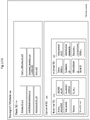
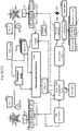
- Fig.07/21- Main system architecture elements diagram, depicting certain sample embodiments of present technology
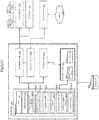
- Fig.08/21- Block diagram depicting of a possible construction of server system that may be used accordance with certain example embodiments
- Fig.09/21- Possible system communication network scheme in accordance with certain example embodiments
- Fig.10/21- Main functional architecture, illustrate certain sample embodiments of present technology
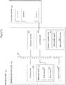
- Fig.11/21- Transportation method in different scenarios in accordance with certain example embodiments (1)
- Fig.12/21- Informational In/Out interfaces diagram, describe certain sample embodiments of present technology
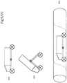
- Fig.13/21- Transportation of multiple modules on track, describe certain sample embodiments of present technology
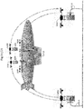
- Fig.14/21- Transportation of multiple modules on cargo airborne ship with usage of autonomous flying drones, describe certain sample embodiments of present technology
- Fig.15/21- Transportation method in different scenarios in accordance with certain example embodiments (2)
- Fig.16/21- Transportation method in different scenarios in accordance with certain example embodiments (3)
- Fig.17/21- On-motion docking, illustrate certain sample embodiments of present technology
- Fig.18/21- Different options of technology usage embodiments (1)
- Fig.19/21- Different options of technology usage embodiments (2)
- Fig.20/21- Different options of technology usage embodiments (3)
- Fig 21/21 - One of possible embodiments of transport module/unit (slot) fixation and blocking sub-system
Detailed description
-
The described technology include the construction principles, operation principles and possible applications of transport and service system and network and system based on the use of automated modular transport platform includes various types of autonomous module transport containers, the description of one of the possible construction of which is shown in Fig.01 /21, its concept, the basic units, elements, sub-systems and option packs, variety of methods (including partially or fully automated) for transportation of cargo, goods and services with the help of autonomous container modules ( Fig. 01 /21), concept and specifics of and operation of the transport units of various types and principles of motion and controlling, one of the possible embodiment of which is shown on Fig. 04 /21, adapted for the transportation of container modules, design and principle of functioning of automated transport and logistics modular system ( Fig. 07 /21), combining all possible modular elements for performing various transport, logistic and service tasks, including the description of the main elements of its infrastructure and the ways of their interaction ( Fig. 10 /21), as well as the uses of this system, platform and container modules for transportation, delivery, storage and dispatching of goods, products, orders and services as well as description of options of the described technology for a wide range of transport and service tasks ( Fig. 13 - Fig. 19 /21).
-
The described technology may include a set of electronic ( Fig.03 /21, Fig.08 /21) and mechanical devices, software, sensors and technical means to collect and exchange information, as well as communication lines and channels ( Fig. 09 /21), providing the solution for tasks of automated transport for individual commercial, service and private goods and groups of goods, as well as the performance of the functions and actions associated with the movement of objects and resources within urban, suburban, rural areas and territories of businesses and organizations. These tasks may include the delivery of commercial, private and other goods, orders and parcels to the addressee, delivery of luggage of passengers, the movement of inventory, components and parts between storage systems and production sites, automated movement of inventory, components and tools within a single enterprise and between enterprises, delivery of consumables, energy and communication sources to places of operation (repair, recreation, liquidation of consequences of failures and accidents, etc.). Also such issues of the movement of objects and tools within the urban, suburban and rural areas may include environmental monitoring task, task of automated scanning for traffic and parking violations by motor vehicles, scanning environment for the condition of the road surface, the level of noise, lighting, vibration, the task of scanning the pedestrians, for example in order to check the wanted persons against databases, as well as other tasks performed by a complex of specialized equipment and technical means. The technology in this case solves the problem of transportation of such a set of devices to the site of monitoring or on the route specified in the monitoring and service tasks. A wide range of services, required movement and transportation process, may be implemented on the base of use described technology as a movement and transportation platform. Scope of application technology includes, but is not limited to these examples. At the same time anywhere herein the words "includes" or "including" means "may have", rather than "shall have", allowing a certain variation in the configuration, functionality and design features. Wherever the text for a description of the design, operating principles or devices specifies the term "optionally", it means the possibility of using this technology without these elements that are optional depending on the particular mode of use of the technology.
-
The described technology embodiment, the modular automated transportation platform, may include two separate basic elements - automated transport container-module ( Fig.01 /21), transport unit ( Fig.04 /21) include autonomous options, and various additional possible elements.
-
Automated transport container module is a standardized (in dimensions of integration platform and integration tools) optionally portable shipping container for placement of payload for different purposes in the inner sheltered space (including freight, portable sources of resources, equipment etc.) equipped with devices and systems to ensure the safety and functioning of the payload, equipped with mechanisms, devices, interfaces and sensors to communicate with external elements and objects (including authentication of access to the contents of transport module), the ability to be installed on and integrated with various devices and systems (including vehicles of various types and configurations, fixed slots for safe storage of containers, smart shopping systems such as "smart shopping cart", specialized systems for loading, unloading and storage of modules, etc.) for perform a wide range of transport, service and information tasks. Depending on the specific tasks the design of a specific container module intended for its implementation may vary. Sets of container module to perform various tasks are stored in a geographically distributed network of special module storage centers (arsenals), and provided to the users depending on their tasks with the help of the transport units (vehicles of various types, principles of movement and control, equipped with transportation platform-stand for installation, fixing the modules and optional devices for integration of energy and information system of the module with energy and information system of the vehicle), under the control of a computerized fleet management system (FMS), which is an integral managing part of the automated transport and logistic modular system, executing functions of management and coordination of movement and actions of transport platforms and its elements in mutual and separate mode, controlling elements of associated infrastructure and providing secure communications within the system network and communications with external systems and users.
-
The customer places an order for transportation of cargo, goods or services delivery to the recipient (which may be the same person or not). The automated computing system (FMS) determines the parameters of the module to carry out the order, determines the specific module from the services arsenal available for a particular order, provides the module at the disposal of the customer or the sender of the order in a certain place at certain conditions determined by the system (on the vehicle, on a stationary slot etc.), and also provides the information, associated with access to the compartment for loading cargo into a module (including transmitted by mobile electronic device of the user, including automatically in mode of data exchange between module and mobile electronic device of the user or with other available method of communication). To deliver services the module is selected with the necessary properties and related equipment. The customer or the goods/cargo sender puts the goods or cargo into the module. The system builds a program task based on the order data to deliver module with the cargo to the recipient. The module after loading the cargo is delivered to the recipient. The system send the recipient information to identify module with the order, the estimated module/order delivery time and place, as well as information for accessing the contents of the module, associated with a specific recipient, a specific module and a specific cargo (order). Accessing information also may send to recipient after module arriving. The recipient, using the information received, locates and identifies the module delivered, enters required information via the information input interface to access the content of the module, associated with the order, accesses order and takes it. Upon delivery of services the recipient is provided access to the service provided by a module delivered, within the parameters specified in order. After receipt of the order or service by recipient the module is evacuated from the place of order delivery to the arsenal for storing or for reuse in another orders. The described technology allows for the implementation of the delivery of the goods or provision of services in the absence of the recipient (in automatic mode/ M2M mode).
Main technology elements and components:
-
One of the two basic elements of automated modular cargo and service system is the autonomous cargo and service transport container module (transport container module or transport module), which depending on the specifics of the tasks may be equipped with various electronic and mechanical systems, is made of different materials with different industrial manufacturing technology, has standardized landing size, accessories for securing and handling of the module, the ability to integrate with a variety of vehicles, systems, platforms, stationary and mobile objects of infrastructure outfitted for integration with the module, and to perform unified and related tasks in integrated form.
-
Autonomous cargo and service transport container module is a self-contained unit for transporting a payload (cargo, goods, components, equipment, materials, resources, machines etc.) that has the standard dimensions of the integration platform (stand), matching the landing slot and interaction interface on the transport unit (vehicle), and serving to perform various tasks, the specifics of which define the functionality design and internal and external engineering of the module. The size and dimensions of the module may vary and are limited by functionality, dimensions of cargo and equipment and capabilities of the vehicle carrying the module for its transportation and loading. However, the description of technology implies that the local implementation includes selection of several options of cargo module size, optimal for performance of most of the potential transportation tasks in the territory or in field where the technology is implement. Fig. 01/ 21 shows the schematic diagram of the structure of one of possible embodiments of autonomous cargo container module, which may include basic (110) and optional (120) elements depends to module functional purpose. Transport module may act as a basket (111) for the secure transportation of at least one cargo unit or several cargo units, including distributed in different trays and pallets inserted inside basket to perform a modular cargoes addressed to receiver, combined basket/cassette for separate transportation of several goods to one or more recipients with a separate handing, the loading platform for placing of other machinery and equipment on it, as well as robots and drones, instrument station, carrying a set and totality of tools to perform a variety of useful work (121, 122) (power supply, onboard command system, memory units, tools for scanning of environment, objects and phenomena, observation, etc.), a robotic platform with a variety of manipulators to perform the mechanical actions of varying complexity and purpose, etc. Transport module according to the functions it performs may be equipped with different systems and their combinations: systems of locking and unlocking the module (system for control of access to payload with automated locking/unlocking servo drive, with other possible types of drives) (113), interfaces for exchange of graphics, text, audio, digital data, and other information (121), LCD panels, readers of biometric indicators, built-in readers of BAR-codes, QR-code, RFID, other identifiers (possible configuration options of possible external interfaces of container module are shown in Fig.12 /21), built-in weights, sub-systems, onboard climate control, instruments of for acceptance and authorization of payments from various payment methods, monitoring and tracking systems (122), objects capture systems and tools, including sensors transmitting tactile sensations, odor recognition systems, sound and voice interface with a speech synthesis function and without it, NFC-markers and receivers (readers), remote module identification system comprising a unique module ID (115), other systems and sub-systems depending on the intended use of the module. Possible functional design of transport module may include, but is not limited to these elements. Besides the fact that cargo transport module is the base part of the transport system, it may also be included as a multiplatform component in the related external systems and platforms, interacting with the transport system (as part of "smart shopping carts" system, for example), or acting autonomously as an independent tool of transportation or delivery.
-
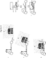
One of the possible embodiments of the container module is presented in Fig.02 /21, in which the mono-basket 200 for cargo and goods with an airtight lid 202 is built into the overall body 201 and may be pulled out of the body for loading cargo and goods. Lid of the basket may comprise additional elements - LSD information panel, a sensor touch pad panel for information exchange, or a solar panel to charging the battery, for example. When lid is closed, the basket is fixed by locking devices 210, prevents unauthorized access to module content. Overall body 201 is provided with grooves 211 for mounting on transport platforms for different purposes (such as "smart shopping cart"), mounts for capturing 203 and pointing mounting devices for integration with the transport units and slots 205 with locking castle, located on the overall integration site (overall body side, designed for docking with the platform of the transport unit, slots for storage and other devices). This device may additionally be equipped with an interface for charging from the power grid of the transport unit or slot, including contactless type. Inside the overall body 201 in the container, in addition to the basket is one or more hardware compartments (207.1, 207.2), which may be placed panels for electric power for module systems, provide a micro-climate system, and other systems and devices required for the functioning of the container module 200. Additionally, the internal housing cavity may oversized command module 204 containing the computer system, a communication module, an antenna, an identification module for identifying the container module comprising a unique module ID, the information storage devices, and other functional elements of the control system of the container module. The command module associated with the system interface and external sensors, which are located on the outer surface of module overall body 201. In addition, optionally container module may be equipped with devices for portable transportation - retractable wheels 208 and the carrying handle 209.
-
On Fig.03 /21 an example of the implementation of the module command/control electronic system 300 is presented, which may optionally be included in the configuration of the module 100 (in the optional internal equipment 122) on Fig.01 /21. As a possible option of the placement of the on-board module command system, compartment 204 is shown on Fig.02 /21. However, depending on the implementation, the command system may be located in other parts of the module or may have a distributed structure. Depending on the specific implementation of the technology, the module command system may be implemented either on the basis of a single electronic device or on the basis of a set of electronic devices linked together by a single bus or via a network interface. In the example of implementing the module command system, it has at least one processor, whose role may be performed a different types of processes depending on the specifics of a particular implementation of the technology: general purpose processor, microcontroller, reconfigurable processor, a graphic processor (GPU), a multiprocessor or any other type of processor unit or device which may perform a commands processing and execute instructions functions (for example various controllers, gated logic like field programmable gate array (FPGA) etc.). Depending to the type and specification of the processor used in Module command system 300 and functions implemented on processor unit may be implemented various types of ISA (instruction set architecture), for example SPARC, MIPS or any other type of ISA. In multiprocessor systems each processor unit may implement it's own ISA (the same or not with other processor units). Depending on the particular implementation processor unit may be performed as a separate computing device, as a set of processing units, separate or combine in one device (chip), with different levels of hierarchy, subordination and interaction between units and processors, with or without combination of the various extra devices (microcontrollers, memory units etc.) or in any combination thereof. According to certain technology embodiments, processor unit together with other components may be the parts of virtualized computing device which executing within one or several other computing devices. Processor unit may operate with data from various data source - data storage (memory unit 330 for example), data flow from various sensors (internal, external and outstanding), data exchanged thru network interface 340, embedded, preloaded or calculated data and program commands of processor unit 310 itself, other data from different data source and with combined data from various data sources.
-
System bus 320 may be or may be not include as a part of module control unit 300 and may play a role of a single computer bus that connects the major components of a computer system, combining the functions of a data bus to carry information, an address bus to determine where it should be sent, and a control bus to determine its operation. In certain embodiments of technology system bus may be replaced on a variety of separate buses adapted to specific needs or not present at all.
-
Module control memory unit 330 may consist of one ore more single or multi memory units, non-volatile or volatile types, in any possible combinations according to specific embodiments of present technology. The option of technology embodiment illustrated on Fig.03 /21 includes two types of memory in memory unit - RAM memory 331 and ROM memory 332. But for different embodiments of presented technology it may be a various types and various versions of memory units in different combination or present as a single memory unit - flash drive, various types of ROM memory (RON, PROM, SPROM, etc.), various types of RAM memory (RAM, DRAM, SRAM, SDRAM, etc.). Also memory unit 330 may work in conjunction with or include one or multiple nonvolatile memory store device (data storage or else).
-
Network interface 340 may be a part of module control unit which role is to exchange data between module control unit and other devices and units attached to the network. To the network interface 340 it may be attached one or several in-built or external network communication devices responsible for data exchange between control module 300 and other devices and systems connected to network, on various different data exchange modes (wired or wireless, V2V, V2I, V2P, V2X etc. via LAN, WLAN, Wi-Fi, Bluetooth etc.). The basic options of network interface is to pass data, connecting and disconnecting with other devices and units. Network interface may exchange data between module control system and other transport system elements (exchange parameters with FMS and transport unit, receive program tasks, orders and commands from FMS, send notifications and alerts, exchange secured ID information, download software updates etc.) directly or with usage of connected external network devices.
-
Controller unit 350 may be a separate computing device or part of processor unit 310 which responsibility is to interfaces control unit with peripheral devices (internal 122 and external 121 on Fig.01/21, power supply, sensors, data exchange interfaces described on Fig.12 /21 or another one, electric drives, electric lockers etc.). Controller unit may use as a main or supported system bus in some of options of module control units implementation. As an example of peripheral devises which may connect and managed by controller unit may be module access/lock subsystem 113 (Fig.01/21), unit/module power interface 112, module fixation/blocking subsystem 114, LSD/LED panels 121, navigation and signal subsystems, external sensors, cameras, other module subsystems. It may be at least one, multiple or single controller units on module control system depends on particular embodiment of technology. The peripheral devices may connect with controller unit 350 trough input/output interfaces 380 or directly. In/out interfaces 380 may use various standard computer connectors (USB, RJ45 etc.), specific connectors, multiplied connections and other form of interactions with peripheral devises.
-
Power supply unit 360 may be integrated thru controller unit 350 (as described on Fig.03 /21), integrated thru the system bus 320 or use other possible ways of integration. It may contain main power supply 361 (chemical batteries of various types and capacity, physical power drives and converters etc.), backup power supply 362, used for the guaranteed uninterrupted power supply of the module control system and its elements, additional sources of power (solar panels, external ac/dc interface, transport unit power interface etc.), which interact with power supply unit trough controller unit 350 or directly.
-
Security module 370 may use as a separate or integrated part of module control system 300 for data encryption and save data exchange within module control system and other module subsystems and external devices. It may contain a data memory drive for storing security data, encryption keys and algorithms, various security systems and elements (software and hardware) for data protection, one or several hardware security modules (HSM), other elements depending of specific technology embodiments. Security module may use for protect data exchanged from compromising, include device ID identification data exchange, other protected data, system electronic signature, PIN protection, any passwords and keys protection, systems and users identifications, other data security purposes. Security module 370 may use preset uncopyable software and media data or use a special separate secure interface for data uploading.
-
The second key element of described technology, Transport units, and their schematic design in one of the possible options of implementation are shown in Fig.04 /21 and Fig.06 /21, but more widely they are represented by any types of vehicle (including unmanned autonomous vehicle - UAV, aircraft, surface or underwater vessel) equipped with a integration and transportation platform 480 or other vehicles, unified for placing of one or more autonomous transport modules on it, tools for loading, unloading and fixing the modules on platform 480, as well as optionally able to be equipped with interfaces to integrate with the energy and information system of modules, capable to have communication and navigation system for determining the unit location and its connection with the transport system elements, as well as a unique assigned ID, recorded in a special secure readable module 430, to identify the unit as an element of the system, interface of transfer of data on this ID to other elements of the transport system and device for ID identification to other elements of the transport system. At the same time integration platform 480 may act as an adapter, on the one side unified for integration with the vehicle, and on the other side unified for integration and transportation of one or more modules with specific dimensions. With the change of cargo platforms the same transport unit may carry cargo modules of different sizes and for various purposes (as well as different numbers of transport modules).
-
As a possible example of the described technology implementation was consider a version of implementation of the transport unit on the basis of an autonomous self-driving vehicle-rover 410, which has a cargo platform for the integration and transport of a cargo module of the "Shopping basket" type, specially designed for the transportation of autonomous transport modules and specialized as part of the proposed technology. However, this does not preclude the use of any other transport platforms for transporting cargo modules, including non-autonomous, including manual loading and unloading of modules and other methods of transportation.
-
Fig. 04 /21 is a flowchart of the design of automated cargo transport unit 400, having an electric drive, a integration platform with dimensions standardized with cargo module 480 size with integration bus 482 to integrate the cargo module with the energy and information system of vehicle (which may be contact, contactless and combined) and (optionally) a robotic device 440 to loading/unloading of transport module and device for its fixation 481.
-
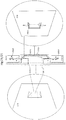
The standard on-board equipment of autonomous transport unit may include a communication station 420 to communicate with a central fleet management system (FMS), transport infrastructure and other autonomous units and vehicles 421, carried out by a variety of ranges and modes of communication (422, 423, 424, 425 and other options), a set of sensors 412 for monitoring the state of the environment, road surface and road conditions, as well as the navigation system 414 for the transport unit orientation in space and information-computing system with software algorithms 411, that is used to processing incoming information (from the sensors, FMS and other objects) and building a program for management of movement and behavior of the unit and the optimal performance of the board tasks. The basis of the autonomous transport unit is a self-driving autonomous vehicle 410. However, unlike the autonomous motor vehicle and other vehicles used for transportation the autonomous transport unit 400 is designed for movement in a variety of modes of urban traffic and different traffic zones: on public roads and highways, on the pedestrian areas and sidewalks, on bike paths and bike lines, on special overpasses, serving to move the transport units separately from the other objects of traffic (through pipes underground/above ground), indoor and covered areas. Also, the transport units may be adopted to use objects of special infrastructure (ramps, elevators, platforms for wheelchairs and bicycles), as well as a line of public transport (special metro cars, special lines of buses and trams etc.). In various traffic areas the transport units use different speed mode, adapted for the environment, and also may be transformed via the transformation sub-system 450, modifying its geometry in order to optimally match the environmental conditions in which they are moving. Fig. 05 /21 shows the variants of possible transformation of the independent rover unit previously described as the example of transport platform prototype to adapt to movement in different traffic areas. To move on the roads and streets the unit (depending on the design of the unit) may take the horizontal "bolide" shape 501 for optimum high speed, reduced drag and efficient high-speed maneuvering. For movement in the pedestrian areas and bicycle paths the transport unit may change the orientation of the working chamber and the module to the vertical or inclined 502 (rotation range up to 90 degrees or more from the horizontal) for greater safety of pedestrians and others subjects of traffic, in order to minimize space requirements, as well as for ease of loading/unloading of transport module or of cargo from module. This provides the ability to vary the different speed modes of the unit for different transport areas. For different types of units (e.g. for trucks) the system stipulates the limit of movement in certain areas. The identification of unit in the system is carried out on the basis of the unique ID assigned to the unit as any other unique elements of the system and stored in the identification system 430, Fig. 04 /21. The autonomous transport units may be driven either by self-contained on-board algorithms, or remotely by the operator, or using combined method, or in automated platoons. Charging of board batteries 416 of the unit is carried out through charging port in parking mode 460, and through recovery drive system and on-board solar battery in driving mode, or charging remotely wirelessly "on the air" (optional). To interact with external systems and users the units may optionally be equipped with a variety of information input/output interfaces 470, including among other things signal system interfaces (signal side lights, horn, etc.), as well as use of information input/output interfaces in the integration mode of transport modules 113, 122 in Fig. 01 /21, configuration options for which are presented in Fig. 12 /21. The unit may be optionally equipped with back-up and emergency systems to improve the reliability and safety 490. The unit may be equipped with power drive in form of one or more electric motors 413 connected to the chassis 415 either directly or via gear system and powered by onboard batteries 416.
-
On Fig.06 /21 is a schematic diagram of an autonomous rover prototype 600, acting as a transport unit for automated transport and loading of container modules. The basis design of the rover may be wheeled chassis 615 and that may have an arbitrary number of wheels. For example, present example shows the device on the basis of a 4-wheel chassis 610. However, the rover may be equipped with 3-wheel, 2-wheel, one-wheeled chassis with stabilizer system of gyroscopes and balances, as well as chassis variants having more than 4 wheels. Instead of the wheel chassis may use other options (trucks, magnetic cushion, etc.). In present embodiment, a complete set of 4 wheels base chassis has a drive to each wheel by a separate electric engine 613 (in the version of "motor-wheel") fed from the onboard battery 616, built in a constructive frame of chassis. The frame has a rover chassis transformation module in the transverse axis 650, equipped with electric drive and allows to transforming the rover to move in different transport areas. Rover may have an equipment/apparatus compartment in the front, which houses the rover control system 611, managed by autonomous algorithms, navigation and positioning system, rover communication system 620, backup systems and devices 690, other devices and mechanisms 614, needed to control the autonomous movement and control of the rover unit, and located on the outside and integrated into the overall unit body hardware sensors and scanning devices necessary for the implementation of the rover self-driving functions. Platform 680 to accommodate container module may be equipped with a gripper (481) for fixing and integrating container module to the rover platform, as well as charging interface (optional). Rover unit also may be equipped with an identification module 630 containing the unique ID of unit in the system, available for secure reading by other authorization elements and systems. The platform 680 is also provided with a system of paired synchronous manipulators 640 for In-gripping, handling and retention of module 200, for example, during the acceptance of module from the storage slot 651. The landline cell to charge the battery during parking rover is also provided with the port 660 for slot-in recharging from stationary power systems.
-
Fig.07 /21 is the schematic diagram of one of possible embodiment of the autonomous transport and logistics system 700, key components of which in addition to the container modules 726 are the transport unit 736 is Fleet Management System/ FMS 710, network of bases-depots for deployment and charging of transport units 730, centers of storage and exchange of modules (arsenals) 720, as well as the communication system consisting of various elements of the system infrastructure, responsible for system communication (713, 723, 734, 743, 752 B), network of stationary points of the module storage and the issuance of cargo 750 and service stations (service centers) 740.
-
FMS/ Fleet Management System 710 in Fig. 07 /21 is a computerized command system, including a set of software and electronic equipment 714, 715, data storage 716 and user and system interfaces 718, responsible for the overall coordination of the functioning of the fleet of transport units and modules, their status and telemetry, processing of orders for the implementation of transport functions, interaction with customers and receivers, collection and processing of telemetry 711, storage and processing of data coming into the system, formation and control of the implementation of program transport assignments, laying the optimal route 712, emergency management, control of the interaction between all the elements of the system 713 and the formation of the system and user reports, as well as encryption and secure data sharing and storage 717. To ensure the reliability and continuity of service the FMS may be provided with duplicate/redundant sub-systems 719 or to operate as part of a replicated FMS network.
-
Bases/depot (block 730 in Fig. 07 /21 ) for basing transport unit platforms are the places of permanent deployment of transport units 736, in which the units may be stored 731, charged/refueled 733 and are served while waiting for transport assignment from FMS. The depot also (optionally) may include the storage arsenals of transport modules 720 for various purposes, as well as automated systems for automatic service of transport units and modules (washing etc.) 740. The depots may be located in a public or private areas (for example in the form of isolated areas in public, private or official parking places for parking and charging of transport units in the case of use of electric vehicles), or as a self-contained underground, ground-based and container units, including single and modular, partially or fully automated 735, with automated access system 732 using ID identification and integrated communication center 734.
-
Arsenal (720 in Fig. 07 /21) is the infrastructure element, responsible for storage, current power supply, basic maintenance of transport modules 726 and its loading on/from transport units. It may be a separate element of the infrastructure, as well as part of the base/depot 730 for the dislocation of modules 726. It may be a part of the base/depot structure 730 (selected area in the depot, the element of automatic depot - in the case of integration into the depot structure), or a separate structure (separate specially equipped room, isolated specially equipped space, including container or modular type), which serves as to perform functions related to the provision of permanent availability of modules 726 to perform transport functions - storage, sorting, delivery and reception, security, charging, assessment of technical conditions (telemetry collection, scanning) and routine maintenance (washing and cleaning) of transport modules, as well as outfitting the service transport modules with the resources and equipment needed to perform the service functions (batteries charge, consumables, etc.). There may be (optionally) a subsystem of automatic loading and unloading 722 of modules into units, a subsystem of storage of unused and reserved modules 721, identification and secure access subsystem 724 to filter access to the modules by ID, as well as its own communication sub-system 723 and the sub-system of processing the collected and received data 725, responsible for communication with the FMS, for collection and pre-processing of data from the modules, as well as for the automated management of processes and mechanisms that are part of the arsenal.
-
Cargo delivery and loading points (block 750 in Fig. 07 /21 ) are the elements of the system infrastructure responsible for storing the delivered modules from the moment of delivery to the delivery point to the moment of receipt of order/cargo by the recipient. They are also responsible for intermediate storage of transport module after its delivery to the point of reception and unloading from the transport unit prior to evacuation from the point of delivery to the arsenal (loading on the transport unit) and storage of available for loading cargo modules in the standby mode. The system includes specially equipped stationary objects, which perform temporary storage and delivery of cargo not demanded by the recipient at the place and time confirmed when placing an order for transport and transferred to deferred delivery mode. The described technique may involve at least two types of delivery points - "Goods Delivery Centers" 752, which consolidate the modules with goods which are not in demand at the time of delivery to the recipient on any territory (regional centers) or "Cargo Post boxes" 751 - certain special places with bracket slots to secure the safe storage of transport modules and their loading and unloading to the units. In the first case "Goods Delivery Centers" 752 may be fully automated or with the presence of the operator. They issue the goods, not demanded by the recipient originally during implementation transport program (for any reason) in a location minimally remote from the point of the initial order delivery. To identify the recipient to whom the cargo is addressed may use the same shipping authorization method as for standard delivery. In the second case, "Cargo Post boxes" represent a special bracket (or section on the wall) equipped with protected slot to safely secure the transport module 751.1 unified with the module fastening system 114 and identical in design to module fixation system on transport unit (481 on Fig. 04 /21), optional - providing infrastructure for charging of the transport module 751.2, and infrastructure for secure access of the units 751.3 and cargo receivers to secure safe storage and protection of module and cargo. To access the contents of the module authorization interfaces 751.4 are used for input information to access, available as possible module equipment ( Fig. 12 /21).
-
The point of delivery of the goods may also be used as the starting point of load/shipment (with availability of transport module or the module pre-order at a certain point). Each point may have a unique ID and security module as the system element (for identification and use of transport assignments), which may also be integrated as part of the delivery point (751, 752) for identifying the place of unloading and loading the modules and place of delivery of the goods to the recipient (including through a secure encrypted remote exchange of identification information with other elements of the system), the coordinates of all the delivery points are stored in the FMS and used for navigation and for creating transport program tasks. Delivery point status (used/free/reserved etc.), is determined by the module after the placement or removal from the point, and reported to the FMS by communication base of the module 723 and service communication system (described in Fig. 09 /21). FMS also has information about the delivery points' status changes planned on the basis of transport assignments and issuing of goods and slots.
-
Service stations (740 in Fig. 07 /21) are the auxiliary subsystem that performs the function of maintenance, inspection and repair of mobile platform elements - transport units 736 and transport modules 726. The works include scheduled replacement of components and assemblies of units and modules (wheels, batteries, lamps and display devices, etc.), replacement of the waste or of defective structural components (actuators, motors, electronic devices and circuit boards, board wiring, suspension aggregates and design panels, batteries, etc.), cleaning, painting of elements or other protective coating, repair and functionality recovery of defective or malfunctioning units, as well as technical diagnostics of the condition and maintenance of structural components and software. Service stations may be deployed both on the basis of conventional garages and auto services, and be specialized for transport units' service 736 (specialized service networks). Service centers have logistics connections with suppliers of spare parts (741, 1074) and components, and they may have equipment 745, required for the test 742, qualified repair and pre-/post-repair storage 744 of transport units and transport modules, as well as qualified personnel, the knowledge base 746 and the technical documentation, or automatic lines for the automated repair and maintenance of the system elements 747. To solve the cases not provided for in the technical documentation, the service centers may organize contact with the support service of the developer and manufacturer of elements 743. For the repair and maintenance of infrastructure elements, electronic computing power, communication devices and other system components and assemblies the centers use specialized maintenance services and resources, as well as mobile service teams.
-
On Fig.08 /21 is an optional example of the implementation of the server system, which may be used accordance with certain example embodiments, for example with FMS 710 or as an element of Arsenals (725) or Bases/Depots (735). The server system may include one or more server units 800 with similar or different server hardware architecture and configuration, one ore multiple system data bases 860, which may be a physical data storing devices, network devices, virtual devices or clusters or cloud data sources. Additionally as a part of server system may be used a various peripheral devices like presented on example network device 841, power supply 832 which may different construction types and may use different principles of work, input/output devices 831, other various connected systems and devices, which may be used with server system according to specific technology embodiment. Inside server unit various components of unit may be communicatively coupled with each other via some communication bus (not shown on Fig. 08 /21), connected directly or use other method of communication.
-
Server unit 800 may include one or more processor units 820, which may be a single processor unit (CPU, microprocessor, Graphics processing unit - GPU, Digital signals processor - DSP, Front-end processor or processors of other types, functions and construction), or multi-processor unit (like multi-core processor and other types of multi-processor systems and devices). Processor unit may responsible to perform a various operations with data source, which is stored on memory unit 810, come from various communication exchange channels (from outstanding devices and data sources via network interface 840, from security module 850, from other possible data source) or generate in processor unit as a result of other data processing. Processor unit 820 may execute one or more programs or algorithms in the same time to implement various functions of Server unit 800. Processor unit 820 may also support quantum calculations (q-bit type calculations) in case of quantum computing devices.
-
Memory 810 may consist a various types of memory units, permanent, volatile or non-volatile (for example various examples of implemented embodiments may include RAM-random access memory units, ROM-read only memory units, various magnetic data storage devices, optical data storage etc.) It may comprise various data sources used for operated different components and modules of server system and other systems and modules. On described example memory unit 810 storing BIOS (binary input/output system) 811 for controlling of basic low-level server unit operations, an operating system 812, which perform control of main operations of server unit, data management application 813, which perform control of general interaction of various data sources and the management of data roles and hierarchies, and various FMS program modules 814, perform and responsible for various FMS functions. On example it is environmental module 815, responsible for control and management of various environment elements (state and deterioration of units and modules, bases fullness etc.), navigation module 816, responsible for various navigation data (for example - for location data of various elements of system infrastructure) and dynamic navigation control of units and modules, operational processing module 817, responsible for main FMS algorithms performance, status control module 818, performed control on system programs status, transport programs module 819, generate all program tasks for all dynamic system elements, and system modules 814-A, may include other system program elements and algorithms. Server memory unit 810 also may optionally contain data relevant for functionality of Artificial Intelligent (AI) or deep machine learning algorithms, which may be a component part of FMS system.
-
Server unit 800 also may use one or more various data storage or system database 860, which may be performed as a separate electronic devise, interacting with the server unit 810 directly or through a network interface 840, as an external database, including cloud base, virtual, distributed or other types of database.
-
The network interface 840 performs communications of server unit with external computing devices, connected to network 842. For example, network interface may connect server unit with transport units, transport modules, units bases, arsenals, with customers thru user interface on they computing devices, with other system infrastructure elements, external data source and other server units. The network interface may connect to server unit thru input/output interface 830 (how its sown on Fg.08), directly, thru system bus or with other methods.
-
Input/output interface 830 may be used as an interaction unit to connect server unit 800 with range of external 831 and embedded devices, sensors and interfaces, used in the process of the server unit 800 operations. It may, for example, communicate server unit with data input/output devices (video displays, keyboards, controller kits, microphones, speakers etc.) permitting system operator or agent interact with the system, connect server system with external data drives, connect server unit with sensors, external ports and with a wide range of other electronic devices. Also in/out interface may use for connect server unit with power supply 832.
-
Power supply 832 is an energy source necessary to maintain server unit functioning and to ensure its operations and to preserve the data used during its operations. It may be a direct grid connection, connection to voltage transformation and stabilization system, to battery or battery's pack, to uninterruptible power supply device (UPS), to solar photovoltaic (PV) panel, to wind powered generator, to energy reactor of different construction types, to other (many) power sources. Its may be distributed for main power supply 833, which used as a main power source for server unit 800 functionality, and backup power supply 834, which may used as a backup system to ensure the continuity of the server unit energy supply in the event of failure of one of the main power sources.
-
Security module 850 may used in a server unit 800 to encrypt data exchange, to ensure the security and protection of transmitted and received data, to authenticate the signatures of items and program elements that use encryption key exchange, and to securely enter, store and exchange of keys which encrypt the data. On example embodiment Security module contains elements as a protected/secured data area 851 and a key management unit 852 that may be performed as a typical HSM (hardware security module) device or may have other design that provides secure entry, storage and use of encryption keys and interaction with other system elements. For example, the security module 850 may connected to the processor unit 820 to ensure the security and signature of the operations performed by the processor. As well as security module may be connected with the memory module 810 to ensure the encryption of key elements of the system, also to ensure the encryption of the interaction commands between the processor 820 and the memory module 810. A wide range of possible encryption technologies and keys types may be used in security module: Triple DES, RSA, Blowfish, Twofish, AES - Advanced Encryption Standard, private keys, public keys, symmetric keys, transport keys, master keys, static keys, dynamic keys, other types of keys and cryptography tools or its combination, quantum encryption etc.
-
Communication system ( Fig. 09 /21) is a set of tools used by various elements of the technology to communicate with each other and with external systems and users, as well as communication channels and networks used for this connection. Each of the elements of technology (transport unit, transport module, depot/base, arsenal, FMS) may have its own communications module (single or multi-channel) (912,913,914,913.1,914.1,918,919), which may perform communication functions autonomously, but all they are linked into a single information and communication system through a communication network 911, function of which may be performed by Internet, LAN network, Intranet, mobile and landline networks, and other connection options, existing or future systems not mentioned here, as well as to build a separate communication network based on the communication between the system elements. The communication system may use a variety of channels and protocols for communication - GSM, EDGE, Wi-Fi, Bluetooth, dial-up, NFC, radio channels of different frequencies, optical communication lines, as well as other channels, protocols and frequencies used for public and special communication and not mentioned here, including (but not limited) to ensure the V2V (vehicle to vehicle) 916.1, V2I (vehicle to infrastructure) 916.2, V2B (vehicle to Base) (912), V2H (vehicle to human) 915 and V2X communication.
-
Shown in Fig. 10 /21 block diagram describes the basic structure and relationship of elements of the automated transport and logistic system, including all the elements mentioned above and described in Fig. 01-09 /21, in their interconnection. In addition, the participants and the transport system elements ( Fig. 10 /21) are: the sender 1040 and the recipient of goods 1050, each of which may be the customer of service (service subject), as well as delivered goods and service (service objects) 1030. Customer (who may be either the sender or recipient) or the external service, through which they place an order for transportation, may be registered and integrated with the FMS system. The registration creates user account in the system, which recorded the minimum data necessary to carry out orders (may be different for different types of orders and different territories, may include and not include the personal data of the customer, the data about their location, coordinates and means of communication with them, payment methods and billing information, and other information, if required). Primary registration of the user in the system may be made automatically in the process of placing the first order. To simplify placing an order the Customer may use his/her user ID assigned to the system, or to use other means of identification (e-mail, phone number, account in social networks, etc.). User registration is performed by user themselves through the UI (on the website or through the mobile app), by operator of a call center or by system's agent based on Customer's application form, based on the processing (automated or manually) of questionnaire form filled in by the Customer, or by other means.
"How does it work"
-
The described technology can help to solve both transport issues of the automated delivery of goods from one point to another (including parcels, orders, food, correspondence, accessories, luggage and other payload), and issues of informational nature: for automated monitoring of areas and collection of information (scanning the environment, weather, noise, pollution, illumination, scanning the road surface and transport infrastructure, scanning of pedestrians and other objects and traffic subjects for various purposes, scanning and recording offenses and incidents, etc.), as well as for services issues: used for the automated provision of various services (delivery of fuel elements and the elements of the power supply, lighting, garbage collection and recovery, automatic mobile ATMs and mailboxes, automatic assistants, etc.) or job. To perform various specific tasks there may be used modules specifically designed and equipped to perform these specific functions, and specific equipment and devices for transport it at transport units and other platforms. The spectrum of use of this technology is not limited to the embodiments described herein, but includes them.
-
Preparatory stage and related technologies - the use of the described transportation technology is preferable in the area that pre-mapped and pre-outfitted with basic systems infrastructure, for which it is possible to make and lay a route of transportation based on previously captured and continuously added mapping and navigation data. So before to start using the transportation system of the described technology in some areas (in any city or district), this area may be prepared (to ensure availability of the necessary infrastructure, to perform primary cartography and navigation linking of location, create a map of the area, tie basic architectural objects, noise and relief to this map, to register in the system and localized on the map the main customers of transport services, to make integration with existing interactive road infrastructure and urban environment where it is possible, to prepare the space for loading and departure of order, to provide access to them for transport units, to install slots for storage of modules and equip the entrances to them). In other words, initial transportation network may be established. Mapping and navigation linking of area may be accomplished using third-party map services (such as Google Maps, HERE Maps, YANDEX maps etc.), and with the help of existing and emerging mapping technologies: aerial photography, satellite imagery, the use of special navigation equipment - navigation trackers installed on vehicles, trucks, trackers and wearable options, roaming by operator. Linking of objects to the navigation data may be made on the basis of post addresses, GPS (Galileo, GLONASS) coordinated locations or other services (e.g., "whats3words"). The desirability of these tasks carried out for the application of the described technology. It should also be noted that the mapping and scanning may be performed not only for roads and streets, but also for pedestrian zones, bicycle lanes and indoor space inside buildings, in which the transport units are supposed to move with separation of zones, scanning places of zones transition and places of transport units access to different zones/from zone to zone. Later on the primary mapping may be adjusted and corrected with the help of information coming in FMS from the units and modules during their movement and environmental and infrastructure scanning. For some embodiments, use of this technology (e.g., using cargo modules without the involvement of an automated delivery system, with manual modules loading, manual loading of modules on non-automated vehicles and delivery by the operator/driver) detailed initial mapping is not required, but the original equipment of the area serviced by technology with basic infrastructure (slots for attachment of modules, properly outfitted storage and charging sites, sites for maintenance, integration of modules with local communication lines and communication networks, the binding of delivery points and infrastructure to coordinate system) is desirable.
-
The following examples of the technology use describe particular cases of the use of the entire set of technical equipment offered by the described technology (modules, transport units with different level of automation, FMS, bases and arsenals, slots and technical stations, other possible components of the system) as automated transport, logistics and service system. However, applications of the described technology is not limited to the examples of use, and are meant to make a selective and partial use of elements of the described technology and options for using elements of the described technology in combination with other technologies of transportation, delivery and storage of goods and services.
-
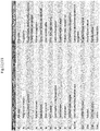
The task of transporting a specific cargo from a particular starting point to a specific (or dynamic) end point or on a specific route using a particular transport module is formed by FMS based on requests from the customer directly via the user interface of the system (for example, via a mobile application), by means of system interfaces through (independent) information system (CRM, ERP or other) or with use of the module itself with the information entered by the customer via the available interface of module (exampled on Fig.12 /21). Transportation request initial application may contain the following information (as an request framework option):
- Transportation type (according to the list of possible types of transportation);
- Place of departure coordinates (address, GPS coordinates, slot ID, etc.);
- Place of receipt coordinates (address, GPS coordinates, slot ID, etc.);
- Route (if transportation along the route is required);
- Name, ID of the sender;
- Name, contact details, ID of the recipient;
- Category of recipient (according to the list of categories of recipients);
- Dimensions of cargo (weight, height x depth x width) and its characteristics;
- Order for the cargo module of a certain category (according to the list of types of modules);
- Category of cargo (according to the list of types of cargo);
- Shipment readiness time of cargo (by default - right now);
- Expected delivery time (time or interval);
- Timetable for the route (if traffic on the route option is chosen);
- Instructions for cargo transfer process (the transfer mode, the recipient contact information, means of communication and authentication algorithm to the case of no delivery, etc. if required);
- Other required characteristics (in particular - the transportation payment method and mode).
-
Some fields that are present in the application, in the absence of specific instructions from the customer may be filled by default (e.g. the "Shipment readiness time of cargo" and other fields). The number of "default" fields also may depends on the type of interface, which is obtained through an order (during order entry via the interface of the module the majority of the order fields may be filled "by default"), some of the fields may be filled by automated ordering system (CRM or other).
-
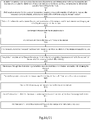
As shown at Fig. 10 /21, accepting and confirming the order (there are different options for the authorization and confirmation of the order depending on the customer type and status, including by entering the customer ID, one-time token password, the user's payment data, "confirm" button on UI etc.), FMS system 1060 with usage of main system capacity performs order analysis, builds the initial route (using the built-in mapping service 712 ( Fig.7 /21), available data on traffic and the situation on the roads, and optionally using automatic algorithms based on deep machine learning technology 714, statistical and historical data, for example), defines the basic criteria for order: required number and type of transport units 1010, distance and power reserve required to fulfill the order, the number and type of transport modules 1020, method of loading and unloading of transport modules, transportation order execution mode, order priority (depending on customer and order type), transportation weight distribution, other variants of parameters for the formation of the transportation program. When these basic criteria are defined, FMS system based on the existing inventory data from the base stations/depots (1011) and telemetry data from transport units 1010 identifies the base station (stations) 1011, from which the transport units will start, transport units ID 1010, assigned to the order, arsenal 1021, in which the transport modules 1020 are stored, that are required to fulfill the order, transport modules ID, base station of the route end where transport units return after order execution, arsenal for storage of transport modules, where they will be returned after the order (or orders) will be completed, the slots to unload the unit in place of loading 1046 (loading destination 1041) and discharge 1056 (receiving destination 1051) of cargo 1030 (if it is planned to upload modules on slot), builds a transport units route across all waypoints, connects the route to the initial route of transportation (building the final route), forms the basic criteria execution of the order (the distance, estimated time for the "took the goods"/"handed over the goods" checkpoints, order execution cost, etc.), forms the program of the infrastructure items reservation and transportation program for each of the involved elements, using the communication system 1090, transmits program to each element involved in the execution of the order (transport units via 913.1 ( Fig.09 /21), transport modules via 914.1, base stations via 913, arsenals via 914, elements of the road and internal infrastructure via 916 etc.), if necessary, waiting for the order confirmation criteria from the external system 1080 (e.g. - proof of payment system what payment order was paid) or users, activates the order execution and sends a notice to the customer, to the goods shipper 1040 (and to the order recipient 1050) of the start of order execution, estimated checkpoints runtime and other critical for customer, sender and recipient data (optional). In case of advance payment requirement for the order fulfillment system reserves the infrastructure needed for order implementation, sending through the external system 1080 (payment system) the request for payment to the customer and waiting for confirmation of payment. In case of non-receipt within the waiting period specified by the system the order and the program are canceled, the booking of infrastructure elements is cancelled by the system as well. Further payment information may be used in billing subsystem for billing purposes. In case on necessary communication with shipper 1040, recipient 1050 of the cargo or other user FMS 1060 thru support/ help desk sub-service communicate with users via available user interfaces 1042 and 1052 (for example via web-interface 1043, mobile application 1044 and 1054, API with internal communication interface 1045, via SMS 1053, or via direct call 1055 or other available interface). After modules 1020 and units 1010 arrived to the final arsenals 1021 and bases/depots 1011, FMS 1060 analyzed environment info from environment control 711 and system data base 716 (on Fig.7 ), if necessary, perform service order for charging to charging interface 1012 and to take necessary power from the greed 1013, or to perform available service 1070 (to clean a platform elements on cleaning spots 1071, to perform in-house service 1072 and ordering necessary spare parts 1074). In emergency cases, accidents and breakdowns FMS 1060 perform request for emergency service 1073.
-
According to the description of delivery method, shown in Fig. 11 /21, upon receipt and activation of program task the transport unit 1108, assigned to perform the specific task, is activated, leaving a charging batteries slot (in case of the unit with the electric drive) in stationing depot 1104-A and starts to move to the first route checkpoint (arsenal 1106-A to get the transport module 1110, assigned for the order program), using its own navigation system, set of on-board sensors (if available), performing the program autonomously under control of on-board software algorithms, under the management and control of the operator (which may be an autonomous high-level information system), in the combined mode, in the mode of following in the platoon, or under the control of the driver. In case of delays or obstacles in the implementation of routing tasks (traffic jams, accidents, streets overlap, construction works, etc.) on any of the sections of the route, transport module 1108 may via the communication system 1102 request from the FMS 1101 task for change of route or build an alternative route independently using on-board autonomous computing and navigation tools and map information, reporting the route change to FMS, as well as (optionally) notifying transportation sender and the receiver on changes in the route and estimated execution delivery time and achievement of checkpoints through messages (text, SMS, POPUP, through social networks and services available through the system user interface, other specified by system functionality and the possibilities of the customer and recipient). Upon reaching the arsenal location 1106-A, transport unit gets access to the zone of issue of transport modules and loads transport module 1110, attached to the order, to its transport platform via an integrated manipulator, with the help of operator, or (optionally) by the manipulator or module loading system, established in the arsenal. After the installation of the transport modules to a transport unit and its fixation on the transport unit platform using module fixation subsystems, as well as (optional) integration of transport module and transport unit in the single related information and energy system through the integration bus on unit and module interfaces. Every transport unit 1108 and every transport module 1110, listed in the system, have their own unique ID (430, Fig. 04 /21, 115, Fig. 01 /21), which may be written, among other things in coded form on electronic cryptographic elements (chips) integrated into the unit or module, which is available for the purpose of secure reading the mutual authentication system elements and to prevent unauthorized or abnormal use or access to the system.
-
After loading the transport module 1110 and the integration of module and unit 1108 integrated system through the communication network 1102 transmits to the FMS 1101 confirmation of the passage of the task checkpoint, leaving arsenal 1106-A and performs program of movement to the next checkpoint of program tasks - to cargo loading for subsequent transportation location 1112. Movement of the combined system of module and unit at all stages of the route may be performed (depending on the transport unit and the transport module type and design) in various transport zones (roads, cycle paths, pedestrian areas, indoor spaces, special overpasses), depending on the zone category, unit selects type of transformation, speed mode and surrounding space and objects scan mode. Optionally possible the transmission of module from unit to unit (in case of insufficiency of resources of one unit to deliver module or the inability of certain type of units to perform movement in the delivery zone), the use of balloons, airships, drones and other aircrafts, vessels for transportation, including the combined use of several types of transport platforms with module transfer therebetween. Data from external devices, sensors and cameras may be recorded in on-board unit memory (or module 1110 memory), and also be transferred to the FMS head system 1101 for storage, processing and use. Depending on the loading point 1112 data access mode for complex to loading point is selected. If the initial parameters do not define a special area or place of loading and do not provide access to it, the complex independently determines the place of parking, as close as possible to the point of loading and taking into account the features of the vehicle selected as transport unit (car, aircraft, ship, automated convertible rover etc.) having the ability to access the operator and cargo for loading and seeking to comply with traffic rules and regulations established for the location of objects and vehicles in this area. After arriving and parking the complex (either directly or through FMS) through a communication network 1102 may sends a notification to the customer on arrival and readiness for loading, as well as may reports required details, and transmits the necessary data (module and unit ID, the exact complex coordinates, instructions and data to perform access to module opening/closing and storage system, etc. if necessary). If access system to the premises for loading prepared and maintained, and the vehicle selected to perform the task has option of access in the premises, the complex enters into the premises and comes to a loading point - module loading port or slot (informing the customer about his arrival and readiness for loading). Then there is a cargo loading process in a module (by the operator or automatically). The operator or the automatic system, using the data for access to the module, transmitted by complex or FMS, provide access to a module (opening module), loads the cargo, and then block access to the module (closing the module). Optionally module loaded with goods may already be in the place of loading (combination of arsenal and loading point) or on module placement slot (1046, Fig. 10 /21). In this case, the customer loads the cargo into the module 1110, and then transmits the module ID as an identifier of cargo at the order transfer to FMS 1101. In this case, the system generates a program task in such a way that the transport unit is sent from the base directly into the cargo (module) loading point 1112 or to the slot (1046, Fig.10 /21), bypassing the arsenal. At the same time, depending on the type and category of cargo, the transport module activates the appropriate program for on-board microclimate in case of module equipped with climate control system (122, Fig. 01 /21) - cargo space may be insulated, ventilated, heated or cooled, the humidity and other microclimate criteria may also be controlled (depending on the presence and design of the onboard module microclimate system). Optionally, the transport unit may load the module to the storage slot at a loading point 1112 and leave it for subsequent loading (go to base 1104). In this case, the module will wait for loading cargo by the sender (by giving him access after identification). Then, the transport program is performed similar to the version with pre-loaded module in the place of cargo shipment 1112 (see above). Also, the cargo module after loading the cargo, using a system of built-in sensors and transducers (if module is equipped with it) may transfer after loading into FMS updated information on cargo and order (for example, the real weight of the load, measured integrated weights). These improved data may be used to adjust the parameters of the order (for example, its price).
-
After loading the goods in the transport module or loading a transport module with the load and blocking access to content of loaded transport module 1110, the complex reports to FMS 1101 the passage of the next transit point on the route, leave the location of the cargo loading point 1112 and performs movement to the point of goods receipt by the recipient 1114. If transport unit 1108 resources (stored energy in the battery, fuel tank, etc.) are not enough to reach the point of receipt 1114, the system may stipulate the module transfer from one transport unit to another, or several such transfers. Such transfers may be carried out both on a route, and at transit bases 1104 (for the safe transfer of the module). At the same time every transport unit 1108, involved in module transportation, must have enough resources to return to closes to transfer point base/depot 1104 which has a free slot for charging and storage of the unit, and the ID of each element involved in the transportation, is included in FMS program task (which also counts resources of vehicles involved in the execution of the program on the basis of telemetry from the system elements and navigation data). Reaching the estimated point of cargo transfer to the recipient 1114, the complex determines the place of optimal parking (if it is not provided with access to the territory or premises of the recipient), and informs the FMS system on reaching the control load transfer point or slot, as well as the exact coordinates, and moves in the mode of cargo unloading/module discharge.
-
The transfer of cargo to the final delivery point may take place both from the machine-to-person (the recipient), and machine-to-machine mode (from the transport unit to the stationary slot/"cargo postbox").
-
After the arrival of the complex 1116 to the cargo delivery endpoint 1114 and transfer through the communication network 1102 the report on reaching checkpoint FMS 1101 may generates a notification for the customer ("reaching the checkpoint" or similar) and for the recipient (about cargo delivery to the delivery point 1114), also containing information on coordinates and module ID, message time, waiting time, the way of the receipt authorization (for example - PIN-code to enter or single use mobile token password for automatic exchange of module and mobile electronic device of recipient to automatically access the contents etc.) and sends the data messages through the network 1102 through the channels provided by users communication mode (PUSH-notification, SMS, e-mail, system message through integration interfaces to external systems, operator call etc.). The variant of the use of technology for sending alerts to users involves not the FMS system 1101, but the transport unit itself 1108, using the on-board software and computer system (411/ Fig. 04 /21) and the on-board communication station (420), sending a message about reaching checkpoints and instructions for authorization and receipt of the goods to the customer, the person who loads the cargo, and the receiver using its own communications system with access to the channels of public communication. In this case, after sending a message to users, complex sends system notification to FMS (1101) on the message sent to users. Sending of messages may use a variety of mechanisms to monitor receipt of messages. If the user has not received a standard message at a specified communication channel, activation is performed for algorithms using reserve communication methods or algorithms of action in case of non-receipt of the goods.
-
The recipient of the goods, taking the message (optionally on mobile communication device) of goods delivery to the final point of delivery 1114 and instructions for obtaining, goes to the complex (or transmit this information to a person authorized by him for receiving the goods, if it is stipulated by system usage conditions), or to the slot to which the module 1110 is unloaded with the cargo. When searching for complex on location it is possible to use the coordinates as well as external alarm devices of the complex, which user may activate to give off short-term signals to identify the location of the complex, using appropriate mobile application interface command on the mobile computing device having a connection with the unit 1108 directly or through FMS 1101. After the arrival of the recipient directly to the module waiting unloading, the recipient, using the received instructions, initiate algorithm for cargo unloading (which may be entering the PIN-code via a built-in module PIN-pad, the activation of the NFC-tag or by credit card through the built-in reader, biometric and voice identification by readers of biometric data embedded in a set of sensors, cameras and microphones, the utterance of the code phrases, verification by entering a password for Wi-Fi network, distributed by module, on the mobile computing device of the recipient, equipped with Wi-Fi module, a different authentication method with the use of input/output interface options which possible options shown on Fig. 12 /21). This possible input/output interface equipment may include as an input options: PIN-pads with buttons to enter codes, fingerprint readers, cameras/face/retinal scanners for face and biometric recognition, microphones, DNA-detectors for express DNA-analysis, card readers to read different cards types, include NFC for remote cards/chips reading, touchscreens, IR-scanners for scanning IR parameters, QR/BAR-code readers; for output information: LSD/LED/Retina screens, speakers, responded holograms, LED indicators, oscillators, other possible types of interface. User also may use as an in/out interface his own mobile computerized devise (smartphone, tablet etc.).
-
Complex may carry out authorization of recipient both in offline mode (between the recipient and complex), and online (between recipient, complex and FMS or a special online sub-system responsible for authorization of the recipient including external one).
-
After identifying and authorizing the recipient, the complex may performs cargo module discharge procedure with the help of built-in manipulators system 440, Fig.04 /21 (releasing module from its locking system on the loading platform), or giving the recipient an opportunity to unload the module. Simultaneously with the release of the transport gripper, access system to the contents of the module is unlocked. From this point on the recipient may open the module and get the contents (the goods). In case of provisional discharge of module 1110 on the slot recipient performs an authorization procedure, using the recipient authorization interface, which is module equipped, whereupon they (upon successful authorization) get access to the load. The recipient who received the module may move it by themselves (with built-in wheels, with the help of auxiliary tools or vehicles, as well as with built-in handles for carrying). Upon unloading the contents of the module, recipient stores a free module are stored on their territory, or transmits to the designated areas/devices/facilities for the storage of free transport modules, which may be located in their territory or near it, or installs the free module in the next available slot for modules (1056 on Fig.10 /21) (at the same time the module determines the slot ID and communicates it to FMS 1101 for creation of program of module 1110 evacuation to the arsenal 1106). The ID of free modules is recorded during its transfer and evacuation (which is automatically read from the secure ID device integrated into the module and the slot, with NFC, BAR/QR-code on the surface of module and slot associated with ID, other automatic identification method, or entered by the operator manually), information on the modules transfer is communicated to FMS 1101, so that the system always knows where the transport modules are, to whom of the recipients and customers they are assigned and when the recipient will return module back. Also the recipient after unloading cargo from the module may order evacuation of transport module by transport unit, in this case the procedure is activated similar to the transportation order, the transport unit arrives to module at a particular programmed time and place, module is removed from custody of the recipient after placement to the transport unit platform and its integration into complex with the unit. The freed modules 1110 are distributed between the arsenals 1106 and, upon delivery to the arsenal, control and cleaning, they arrive for subsequent use.
-
There is a variant of unloading the transport module 1110 contents without unloading it from the transport unit 1108. To do this, the corresponding transport option must be activated during the formation of the transportation order in the FMS. In this case, after delivery of the complex to the point of delivery identification and authorization by the recipient the system is activated for access to the goods in the transport module (module remains fixed on the platform and integrated with the unit), access system disables cargo lock access interface, user gets access to the contents of module and independently unloads it. After unloading the contents (the goods), user activates the complete procedure of delivery or procedure activate automatically; the system closes the module, blocking access to it and activates complex return algorithm to the arsenal 1106 (for module) and to the base 1104 (for transport unit).
-
There is a variant of unloading of transport modules from machine to machine (device) with the subsequent issue of the module or its contents for the recipient. In this case, when placing an order, the instructions for obtaining the goods may additionally contain information about the type of device for transmitting of module/cargo, ID of the device, information on coordinates and access to the device, information about the process of unloading the module/content, other information necessary for the unloading. Upon arrival of the complex 1116 to the place of unloading complex sets remote communication with the system receiving module/cargo on the receiving device (NFC, other variants of the communication protocol, visual identification, etc.), determines its ID, comparing it with the one contained in the transportation program, and is set to position required for unloading. Then the procedure of module 1110 discharge is performed from the unit platform 1108 and transfer of it from transport unit to the received device (e.g., stationary slot for modules storage 1056 in figure Fig.10 /21) without unlocking system of access to content. Once the module installed on the discharge and storage device, storage and subsequent issue of module/contents to the recipient is provided on the module storage device. The transport unit 1108 after completion of the module/cargo transfer procedure to the unloading and storage device and after fixation of module/cargo on the device receives acknowledgment from the module 1110 on integration with the storage device, activates the program for return to depot 1104 and returns to the base. In this case, cargo delivery to the recipient takes place independently and permanently with module installed on the unloading and storage device, (for example - on the slot for the modules).
-
If the authorization of the recipient in the complex unlading mode without issuing modules and unlocking access to content there is no discharge, or some cargo remains in the module (or the user loads their own cargo) - the system generates (after expiration of the monitoring time/deadline) a notice to the user to obtain the cargo and blocks access to the module. Repeated access to module is possible by the user's authorization. If at the end of the monitoring time the user does not unload module's contents (or does not unload the module), the system may activate the goods transfer process to the point of cargo delivery 1118 (or cargo return), all participants of the transport communication are sent a notice (the content and method of transmission may be different for each participant).
-
In case of failure of cargo receipt by the recipient at the point of order delivery, the lack at the point of delivery slots available for discharging modules and excess of the allowable waiting limit of the order receiving complex the cargo delivery program to an intermediate center of delivery is activated, FMS 1101 calculates a new program for the complex 1116, sends the program to complex to execute, and sends to the sender and recipient via a communication network 1102 a notification with information on sending the order to the intermediate center for storage and delivery of goods (752 on Fig. 07 /21, 1118) and the instructions on the time/storage mode and procedure of issuing the module/cargo in the storage center. Next the complex 1116 independently moves from the point of goods delivery to the cargo storage/delivery center, specified by FMS. Implementation of the system may involves a variant in which a complex upon reaching deadline independently generates the program for the cargo delivery to the nearest delivery and storage center (752/1118), sending system messages and notifications to the recipient and the customer/sender. In this case complex needs to get the confirmation from orders delivery and storage center 1118 or from FMS 1101 to this program. Then, upon reaching order center, the procedure is implemented similar to discharge of module and transferring it to operator or automated storage system (without unlocking content access system). The module is sent for storage to the orders issue center 1118. Recipient, upon arriving to the orders issue center, passes the authorization procedure, after which they are given the module or its contents. Unclaimed goods/modules after set time are returned to the sender (or other procedures are carried out in respect of their contents provided for cargo delivery mode).
-
If abnormal situations occur at some stage of the process associated with the interaction of fully autonomous version of the complex and people, the complex may remotely connect an operator. In this case, the higher-level system or the operator by means of system communications 1102 and build-in camera, sensors, detectors and alarm devices ( Fig.12 /21) can connect to the process of human and inventory interaction in order to assist in the communication, to instruct the person, specify the problem or fix the error. Also, the system or, if necessary, the operator may use the complex to organize the customer and recipient communication with the other sides of transportation process. The operator or a higher-level system may also discretely monitor the process in any of its parts, as well as remotely stop, managed or correct work of the complex 1116, if necessary.
-
After discharging the module 1110 and getting from the system the confirmation of its delivery the unit 1108 activates program for the return to depot/to the base 1104. At the same time the base where unit returns may have a different location compared to the one from which unit departed. Upon arrival at the base unit is installed in storage place/slot, if necessary, connected to the charge interface/greed to ensure the charging/refueling, and also transmits telemetry information on the status of its components, the mileage, the level of battery charge and other to the base and the FMS system. If necessary, the unit is sent for maintenance, service or spare parts replacement. If the delivery procedure was used without discharging the module, then before being sent to the final storage base/to slot the unit delivers the empty module to the arsenal 1106-B, where it is discharged from the unit (similar to above), after which unit is sent to the end base for storage and refueling / charging (1104-B).
-
Variant of described technology with pre-loaded modules involves the option of collection and delivery of modules with goods from the customer to the recipient not by individual unit in autonomous mode, but by the truck, capable of carrying a large number (two or more) of modules at the same time, in combination (optional) with independent unit, responsible for the loading and unloading of modules on the truck, as well as the delivery of the modules from the truck to the users and storage slots and in the opposite direction. Figure Fig. 13 /21 displays the abovementioned variant of implementation of the proposed technology 1300. On the base of the truck 1310 (which may be both autonomous, and human-driven, or may move in combined mode) there is a cargo compartment 1320, including slots for cargo modules and the modules themselves 1350, device for sorting and issue of the modules 1321, port for receiving and dispensing the modules 1340. Additionally the complex includes the platform 1360 (which may be implemented as an external module or the element cargo compartment embedded in the body of the truck), which can hold standalone unit - rover 1330 with manipulator arm or without it. When processing orders for transportation of modules loaded with a cargo, FMS system may build a circular route for such a cargo system, including truck, providing for cyclical movement along the route of several (multiple) points of loading and unloading the modules (at least one). In case of the formation of such a program and transfer it to automated system or to a truck driver (in the form of routing task) complex consisting of a truck 1310 and the unit 1330, which is located on the platform 1360, or arrived to the each point independently, moves along the charted route from places of loading to the places of unloading. With the arrival of the complex to the loading site the truck 1310 is parked closest to the module loading location coordinates, moves down the platform 1360, the rover unit 1330 leaves it (in case of unit pre-loading option), independently on the basis of the individual program moves to the module 1350, loads it on its integrated surface or platform, and then returns to the truck platform 1360 and takes the position for loading the module in the truck. Platform 1360 lifts the unit with the module to the cargo reception port 1340, after which the unit may use the manipulator sub-system to perform the loading of module to the module storage and sorting system 1321, located in the cargo compartment 1320. Then unit may leave the truck or stay on platform till the next operational task. After that, the truck moves to the order delivery site, wherein it parks as close as possible to the delivery point coordinate, module sorting sub-system 1321 performs the delivery of the module, associated with the cargo at the point of delivery, to the port of delivery of the goods, where the module is transferred to the unit 1330 platform, after which the cargo platform 1360 drops the unit and it transfers the module with cargo to the delivery point where it transfers it (or cargo, depending on the delivery program) to the recipient, or loads the module to storage slot. After this the unit returns to the platform (or move independently) 1360 and the truck 1300 continues the movement along the route. Described embodiment similar to truck option, but with individual drone units moving through the air and cargo mother airship, moving along cyclic route and carrying cargo modules in cargo compartment (as well as recharging the drones for delivery) is shown in Fig.14 /21. Cargo transport airship 1410 moves in cyclical or circular route over the ground at the height prescribed for the movement of aircraft of this type over settlements, managed autonomously, by the operator or pilot. The airship may be equipped with transport compartment 1420 with the established system of module sorting and storage. Also, the airship may have automated ports for loading (1440) and discharge (1441) of modules. Also the airship may have port platform (1432) for landing the copter drones equipped for recharging their batteries (in case of electric copters) or refueling them. Transport copter drones have capture manipulator to perform a secure grip and transportation of transport modules in the air. Copter drones may move both in autonomous mode and in operator control mode. Also, besides the screws drones may have capacity(s) filled with lighter than air gas mixture to generate lift, energy saving and improving reliability in flight. Upon the airship reaching area under which there is a storage slot 1451-A with installed module with cargo the copter drone 1430 starts from the platform 1432, moves to the slot 1451-A, uses the manipulator 1431 to grab the module 1450 (at this, upon being grabbed by manipulator module frees the lock for fixation with slot), and transports the module 1450 to the module loading port on the airship 1440. Upon reaching port 1440, drone unloads the module 1450 to the port receiving system, after which it enters the module storage and sorting sub-system 1421 on board of the airship 1410. Drone at the same time may land to the platform 1432 for charging or it can be used for other transport tasks. When the airship, moving along the route, reaches the slot location area in the place of module discharge 1450, the module through the sorting and storage system 1421 and the discharge port 1441 arrives for the discharge and capture by copter drone 1430, which upon capturing the module moves it and installs on the discharge point 1451-B, and then returns to the airship for recharging.
-
The described technology also suggests the possibility of automated loading and unloading of the module to the unit in the luggage compartment of the car (including the autonomous self-driving on), provided the vehicle and the luggage compartment equipment with information and technical systems for integration and interoperability with technology and its elements. In this case, the transport module may be used for transporting goods and commodities in the cargo compartment, and as a backup or additional source/power battery for an electric vehicle (subject to implemented integration of battery module and a vehicle power system).
-
In case when the task selected is the mode of movement along the route (territory patrol mode, scan mode, etc.), transport module for the task should have specific equipment and design (contain a set of necessary equipment, interfaces, and external and internal sensors). System task to perform patrols may contain the following information:
- Patrol type (according to list);
- Coordinates of the route start (address, GPS coordinates, etc.);
- Coordinates of the end of the route place (address, GPS coordinates, etc.);
- Patrol route (map, route checkpoints and their sequence);
- Name, ID of the customer;
- Patrol start time;
- Schedule and mode of movement along the route;
- Type/code of transport module (according to the list);
- Guidelines for unit procedures for interaction with module systems (independent mode of movement along the route/associated driving mode along the route/slave mode of movement along the route);
- Instructions for using the unit and module sensors in the process of patrolling and mode of transmission of information from the sensors to FMS (or to the external information system);
- Other relevant information (if necessary).
-
Fig.15 /21 is a diagram for performing transport tasks using systems and platforms that are included in the considered technology, associated with movement on a certain route (patrolling a certain area). Upon accepting and confirming the order on patrol (select different options for the authorization and confirmation of the order, depending on the customer's category and the status), the FMS system performs order analysis, builds the initial route (using the built-in mapping service and available data on traffic and traffic conditions, 1064, 1065 on Fig.10 /21) on the basis of route from the order, defines the basic criteria for the order: the required number of transport units, distance and power reserve required to fulfill the order, the number and type of transport modules, the method of loading and unloading of transport modules, order execution mode, order priority (depending on the customer and order type). When these basic criteria are defined by the system, the system based on available inventory data from the base stations/depots and telemetry data from transport units determines the base station (stations) 1501, from which the transport units will start, ID of transport units assigned to the order, the arsenal, which stored transport modules that are necessary to fulfill the order, ID of the transport modules, base station for route end where transport units will return after the execution of the order, arsenal for storage of transport modules, where they will be returned after the order is fulfilled, builds the route for movement of transport units between these points, links this route to the initial route of transportation (build the final route), forms the basic criteria of the order (distance, estimated time for the checkpoints, value of the order execution, differing depending on the order category and customer), generates a program for execution of transport order for each of the involved elements (1502), using the communication system transmits the program to each element participating in the execution of the order (transport units, transport modules, base stations, arsenals, elements of the environment and internal infrastructure) 1503, activates the execution of the order and sends a notification to the customer of the beginning of the order, expected execution or performance time of checkpoints and other critical customer data (optional).
-
Upon receipt and activation of program task the transport unit specified for the job is activated, leaving the base/depot where it is based and starts to move to the first checkpoint of the route 1504 (to the arsenal for the transport module assigned to the task), using its own navigation system, complex board sensors, autonomously executing a program under the control of the onboard software algorithms, under management and control of the operator (which may be an autonomous top-level information system), in the combined mode, and follow mode in the platoon and under the control of the driver. In the event of delays and obstacles in the implementation of route task (traffic jams, accidents, streets overlap, road works, etc.) on any of the sections of the task route, the transport unit may via the communications system request from the FMS the rerouting task or build an alternative route independently using on-board autonomous computing and navigation tools and map information, notifying a route change to FMS, as well as (optionally) notifying the customer on changing the route and the estimated execution time of the achievement of the checkpoints by means of messages (text, SMS, POPUP, other specified by functionality of systems and possibilities of the customer and the recipient). However, the main patrol route (the order route) may not be changed by the transport unit alone without customer confirmation. Reaching arsenal location, autonomous transport unit gains access to the dispensing transport module zone and loads a transport module assigned to the task to its transport platform via a built in manipulator, with help of operator or (optionally) via the manipulator or module loading system installed in the arsenal 1505. After the installation of the transport module to an integration platform or surface it is fixed on the transport unit using module fixation sub-system, and integration of transport module and transport unit into a single connected information and energy complex through integration bus (482) of unit and module interface (112). Mutual identification of unit and module by ID and comparing the read ID with the transport task data is allowed.
-
After loading the transport modules and module and unit integration the combined complex sends confirmation to FMS of the passage of the checkpoint of the task, leaves the arsenal and executes the program of move to next checkpoint of programmed task - the start point of the patrol route. The movement of the combined system at all stages of the route may be done in different transport areas (roads, cycle paths, pedestrian areas, indoor spaces and rooms, special overpasses), depending on the category of the area in which is located the system, the rover unit (in the case of its use as a transport unit) selects the type of transformation, speed mode and environment scan mode in Fig. 05 /21. Data from external sensors and control devices, sensors and cameras may be recorded in an onboard memory of unit or module, and transmitted to the host system (FMS) for storage, processing and use. After arriving at the starting point of patrol complex sends the system message to FMS about passing a checkpoint, or FMS transmits to the module the information on reaching the checkpoint of the route to activate patrol instruments, as well as (optionally) notifies the customer of the start of the patrol 1506. Later on the movement of complex along the patrol route is performed depending on the selected patrol mode 1507 - if the independent patrol mode is selected, the unit carries out the movement along the route, regardless of the actions and procedures performed by the module equipment. If the combined mode is selected - the movement along the route is controlled by combination of navigation and control systems of unit and smart module system, if the dependent mode is selected - movement of unit is controlled by the module and its electronic systems. In dependent and combined mode operator or system that controls patrols may take control of the complex, interrupt, change modes, as well as program the movement on the route, change the route, remotely control the complex movement.
-
After completing patrol route, the complex reports to FMS on passing the checkpoint, on the time of its passage, and other telemetry data 1508, required to evaluating results of patrol. The module used for patrolling may transmit data on patrol separately to special (independent) system of patrols monitoring and control 1509 (or via the build-in FMS sub-system).
-
After completion of the patrol program the unit may receive from FMS a program task for the transfer of module with patrol complex to the arsenal and for return of unit to the base. Upon accepting and activating the program, the unit moves to the arsenal determined for the module storage, where it discharged the module 1510, and then leaves the arsenal, moving to the final base and enters the port for unit storage and charge of its internal batteries (in case of the unit with electric drive) 1511. Optional may be a variant when at the end of the patrolling program the complex independently recognize the nearest arsenal and base for the storage of module and unit, communicates with arsenal and base for reserved slots, build the optimal route to the storage bases and transmits to FMS final system message with parameters of the routes to the storage base.
-
In case the described technology may used for delivery and providing the service, the design of module service container shall ensure the service providing by the module. System task for rendering the service in this case may contain the following information:
- Transportation/service type (according to list);
- The coordinates of the services delivery place (address, GPS coordinates, route, slot ID, etc.);
- Name, ID of the customer;
- Name, contact information, ID of the recipient and the channel(s) of communication with the recipient;
- Estimated time of receiving the service;
- Parameters and scope of ordered services;
- Type/ characteristics of the transport module/service type (according to the list);
- Instructions on the procedure of interaction with the module system (interaction ports, communication protocols, size and type of physical and commutation interface, services recipient authorization mode, identification mode for the start and end of the service, etc.).
-
Fig. 16 /21 is a diagram of the proposed technology elements implementing service tasks of the mobile providing of resources. Upon accepting and confirming the order for the service provision, the FMS system produces order analysis, defines the basic criteria for the order: coordinates of order delivery, coordinates of the bases and arsenals containing units and modules that are necessary to fulfill the order, the required number of transport units, distance and power or fuel reserve, necessary to fulfill the order, number, type of transport modules and their characteristics 1601 (charge capacity and ports in case of mobile batteries, volume/capacity and tank type in case of delivery of liquids, communication station parameters in case of mobile communication center ordered, characteristics of the speaker in case of order of mobile speaker and so forth), the method of loading and unloading of transport modules, order performance mode, order priority (depending on the customer order and type). Once these basic criteria are defined, the FMS system determines the base station(s), from which the transport units will start, ID of transport units assigned to the order, the arsenal that stores transport modules that are necessary to fulfill the order, ID of transport modules, the desired composition of the contents of the module, the base station on the end of the route, where the transport units will return after the execution of the order, the arsenal for storage of transport modules, where they will be returned after the order execution, builds the route for movement of transport units between these points, forms the basic criteria of the order (distance, estimated time for the checkpoints, the value of the order, etc.), forms the program for execution of transport order for each of the involved elements 1602, using the communication system transmits the program to every element participating in the execution of the order (transport units, transport modules, base stations/depots, arsenals, elements of road and internal infrastructure) and activates the execution of the order 1603.
-
After receiving order from FMS the arsenal, which stores a transport module assigned for fulfillment of the order and arsenal modules loading system (1022, Fig.10 /21), performs charging/refueling of assigned transport module with necessary ingredients and contents as well as the setting of onboard equipment, interfaces, and adapters for the execution of the order (the action is performed autonomously or with the help of the operator). After the module and its contents are within the set parameters for the job, information system of arsenal sends FMS a confirmation of module readiness to perform service functions 1604.
-
After receiving confirmation of module readiness (or during its preparation) FMS performs the activation of the transport unit program at the depot, selected to fulfill the order and sends a notification to the customer of the beginning of the order, estimated runtime of checkpoints and other data critical for the customer and recipient (optional). Upon receipt and activation of program task transport unit specified for the job is activated, leaving the port for charging the battery at the home base and starts to move to the first checkpoint of the route (the arsenal for the transport module assigned for the task) 1605. Upon reaching arsenal location, the transport unit gains access to the transport module dispensing zone and loads a transport module attached to the order to its integration platform/surface via a built-in manipulator, with the operator assistance or (optionally) via the manipulator or module loading system installed in the arsenal 1606. Identification of units and modules, forming the order complex, is performed on the basis of their ID, recorded on readable protected elements (chips or another possible devices and tools) by means of encryption and the ID data, contained in FMS program task. After the installation of the transport module to the integration surface or platform 480 ( Fig. 04 /21) it is fixed to the transport unit platform 400 with the module fixation sub-system 481, and the transport module and transport unit may integrated in the single combined information and energy complex through the integration bus 482 of the unit and the respective interfaces of the module (112, Fig.01 /21).
-
After loading the transport module and integration of module and unit the combined complex sends to FMS a confirmation of the passage of the task checkpoint, leaves arsenal and executes the program of move to the next checkpoint of program task - to the place of rendering services/services' recipient location 1607. The movement of the combined system (complex) at all stages of the route may be performed in different transport zones (roads, cycle paths, pedestrian areas, indoor spaces and rooms, special overpasses), depending on the category of the zone in which the system is located and the unit design, unit chosen type of transformation, speed mode and environment scanning mode. Data from the onboard sensors and control devices, sensors and cameras may be recorded in an onboard memory of unit or module, and transmitted to the host system (FMS) for storing, processing and use. After arriving at the point of service rendering the complex transmits a system message to FMS about passing the checkpoint, the unit transmits to module directly or thru FMS an information on reaching the checkpoint for the activation of tools providing the service, as well as (optionally) notifies the customer of the service delivery to the point of service rendering. Service rendering point may have fixed position, but it also may have dynamic position (for example, it may be linked to the coordinates of the mobile communication device associated with the recipient of the service or to the determined moving object like a car). In the second case complex searches for the customer and determines the service delivery location on the basis of the dynamic data of the location (for example) of associated mobile device, transmitted by it via the communication network and information systems to the FMS or directly to the complex.
-
After completing the delivery of module to perform service functions, the complex notifies the recipient of the arrival of service module to the point of the order execution, and transmits the exact coordinates of the unit and module and landmarks on the terrain/map (via communication methods specified in the order) and instructions for the recipient authorization procedure 1607.
-
Once the service recipient detects and identifies the complex, the recipient passes the authorization procedure (following the instructions) - either by inputting control data or by reading biometric data, or by using electronic keys for authentication (including remotely automatically readable), or using another (or combined) methods 1608.
-
After the recipient authorization procedure and confirmation of their identity the system activates algorithm for providing the service, as well as (optionally) the unloading of the transport module 1609. The transport unit after discharge of the module is sent for final storage base. Transport service module remains at the disposal of the service recipient until the end of the rendering of the service function, or until the exhaustion of the resources necessary to perform the service function. A control sub-system for monitoring the quantity or volume of the issued resource may control the quantity or volume of the resource for issuance specified in the module program. After the quantity or volume of the resource given is reached in the program task, the control sub-system stops issuing the resource. After the exhaustion of the resource, or the end of the performance of the service the module through its communication system transmits to FMS information about readiness to be transported back and about its location. FMS forms the order to the next transport unit to load module at its location and to return the module to the arsenal, which the unit performs. There is a version of the service function without unloading module; in this case, the entire complex is located in the place of the provision of services till the end of its rendering or until the exhaustion of the resource in the module, after which the transport unit returns the modules to the arsenal for recharge and subsequent use.
-
Upon completion of the service function 1610 or the exhaustion of the resource the module transmits the relevant system information to the FMS, which generates and transmits the command for the unit to evacuate the module to arsenal 1611 for recharge and subsequent use, and the subsequent return of the unit to the base for storing and charging 1612.
-
There is a version of the serial (continuous) rendering of service with consistent replacement of transport modules/complexes with expended resources with new ones. The variant of using modules and transport units for providing the service may be order to ensure the supply of the object by some resource for a certain time (for example, providing electricity for street campaign or event). In this case, several (at least two) units with modules connected to each other (1116 at Fig.11 /21) are delivered to the place of the event 1114. Power supply of the object is connected to one of the modules, which acts as the energy hub. Power supply is activated at preset time. As the dependent modules charge is depleted, they are replaced with charged ones. This ensures continuity of power supply of the object. At the end of the event (the time of completing the order for power supply) all the modules are returned by units to the arsenals for charging and later use.
-
Fig.17 /21 offers the option of providing similar services to provide power or charge, but in motion, where the complex may be used to charge electric vehicles or refueling vehicles on the go. When ordering this service, the vehicle to be filled 1703 may be equipped with their own autonomous management system, identification systems, V2V-interface that is compatible with unit systems, navigation and positioning systems, communication with the FMS and the port for receiving energy or fuel on the move. When receiving an order for refueling or charging on the move, which may be formed by on-board electronic system of the vehicle (including autonomous), the FMS determines (based on the data transmitted by the vehicle) the vehicle route, the power reserve and the need for energy (or fuel) as well as speed limit, which must be maintained during charging. Based on these data, and data from bases (which are located along the route of movement and which may host, among other, the on-duty complexes 1702, consisting of units and modules with batteries of high capacity and automatic buses for charging 1704 in case of charging electric vehicle) FMS creates the program for order fulfillment, determines base, unit and module for order fulfillment, creates the program for order fulfillment, including the route of movement and information necessary for identification of the customer's vehicle and gateway for charge. After program activation the complex 1702, allocated for fulfillment of order, starts from the base, and begins to move along the route with the speed necessary to get closer to the target vehicle. The complex and the vehicle in motion transmit to the FMS or to each other navigation information about their location and get information on the location of target/module. Entering close proximity (P.17-1/21), the complex 1702 and the target vehicle 1703 establish information V2V contact through their information networks. Later on the target vehicle and complex act as a unified information system. It is necessary that the vehicle at this point of the order fulfillment have been transferred to the autopilot (and was equipped with an autopilot system) or to the mode of active automatic following in the platoon, in which the vehicle plays leading role for the complex. If it will continue to be controlled by the driver, the driver shall be warned about the synchronization of vehicle and complex driving processes, on non-appropriateness of abrupt changes of speed limits or driving direction and on possible delay in the reaction of systems and components of vehicle and unit. The vehicle, which is in active mode, may transfer all telemetry parameters on the operation of its systems (control system, acceleration and braking systems, etc.) to the unit in the V2V communication mode ( Fig. 17-2 /21). After convergence and establishing contact vehicle and complex begin to move as a single unit, with the regime and the characteristics of the movement being specified by vehicle systems. Complex 1702 takes the position as close as possible behind/in front of the vehicle and exactly follows its movements, keeping the distance necessary to transmit the charging bus 1704. The system of the vehicle and complex moves as a single platoon controlled by the vehicle. After establishing a stable connection between the vehicle and the complex the vehicle releases the charging port 1705, located on the side of the complex, and the complex extends controlled flexible charging bus. Charging port 1705 is outfitted with a target sensor and the bus 1704 is outfitted with sensor to locate and connect to targets and mechanisms for the orientation of the transition connector. Finding a charging port 1705, bus sensors allow it to make the insertion of the connector into a port. After receiving confirmation of contact the command system of the module activates the vehicle battery charging process ( Fig. 17-3 /21). Wireless short distance electric vehicle charging system (https://www.pluglesspower.com as illustration), installed on complex may be used as an option. If a maneuver is needed (deceleration or acceleration, lane change, turn) the vehicle manages the complex motion, transmitting commands (through remote information channel or/and through an integrated bus for power supply) through V2V interface. After the charging cycle end the complex disconnects the bus and the port ( Fig. 17-4 /21), confirm with vehicle the end of connected mode and starts the independent movement on the road. After this (under control of FMS) program is activated for the complex return to the base and its further use. This same service for the vehicle charging may be executed by complex not in motion, but in the parking lot when the vehicle is stationary. In addition, the module with high capacity battery and interfaces to integrate with on-board electric network of vehicle that is installed in the luggage or service compartment of electric vehicle and fixed there with the help of a regular module locking device 114 ( Fig. 01 /21), may act as a highly mobile reserve element for electric power, which may be quickly installed or replaced when the resource of the main onboard battery is exhausted, including through the delivery and replacement of such a module on call by transport platform to the place of location of the electric vehicle, including preventive call or automated ordering.
-
Technology similar to that described for the subordination to the control system of the vehicle, and complex may be used when driving in platoon of several units controlled by head unit or leader vehicle. This mode may use both sequential chain of subordination of units in platoon, in which each of the complexes in the chain following the head control module is the link that transmits control commands to the following complex, and parallel subordination scheme in which all the dependent units are connected to the head leader unit and managed by them, or combined one (when each dependent unit associated with leader unit, but interacting with its neighbors in the chain). When in sequential or combined model of connection the intermediate complex during the platoon movement implements its program and leaves the platoon, this is preceded by procedure of switch of the complex, following it to be managed the complex right before it.
-
The transport system (units) may also be a platform for transportation of other mobile robots or mechanisms (for example, transport robot STARSHIP: https://www.starship.xvz, Domino's DRU: https://www.dominos.com.au/inside-dominos/technology/dru and other similar devices), the variant is shown in Fig. 18 /21. In this case the transport unit is a platform 1800 with fixation system 1801 and manipulator 1802 that performs functions of loading/unloading and fixing of device on the platform, fitting the dimensions and design of transported mechanism, and (optionally) a ramp for arrival and departure of the transported device 1804. In addition to the devices that move on the ground, transport unit and transport module can carry one or more of the aircraft devices (including remotely controlled or autonomous). The order for the transportation of device may be similar to the order for delivery of the goods. In this case the loaded mechanism 1804 may independently arrives to the point of loading ( Fig. 18-1 /21). An important condition is the implementation of option of mutual authentication of unit and the loaded mechanism. Next, passing mutual authentication procedure, the unit performs loading and locking of mechanism on the platform using its manipulators or loading devices of platform 1803 ( Fig. 18-2 /21). This is followed by delivery of mechanism to the point of delivery and its subsequent automatic discharge ( Fig. 18-3 /21). After this the mechanism (1804) may continue the independent movement, the unit with platform may return to base.
-
Optionally integration platform 480 may act as an independent transporting device (1805), intermediate between transport unit 1800 and transport module 200. In this example of technology embodiment integration platform 1805 may be equipped by different manipulators, devices and mechanisms, operated autonomously independent from transport unit 1800 systems or in collaboration with these systems, to perform various specific functions depending on specific transportation and service tack. It may be a manipulators for manipulations and loading procedures with transport modules, set of manipulators and artificial legs (or wheels) for self-transportation of platform with and without the module in specific area and environment, electric drives, electronic computing devices for perform management of equipment and devices, installed on platform, sensors, batteries and other energy sources for autonomous power supply of equipment installed on platform. Also this type of transportation platform may have two systems for fixation - one equal to fixation/blocking sub-system 114 of module to fix the platform with unit body and their fixation sub-system 481, and another for module fixation sub-system 481 to fixate the module on transportation platform. The set of devices with which transportation platform 1805 may be equipped differs depending on specific transport task, performed by complex. Depending on this task transport unit may be equipped by removable integration platform at first, and then loaded the module on platform. After unit 1800 deliver module 200 to delivery destination, integration platform may perform manipulations with module (unload it with embedded manipulators for example) and stay on unit (return with unit to the depot), or disconnect from unit 1800 together with module 200 and perform further movement separately as a independent transport platform (for example, to overcome staircases if platform 1805 is equipped with a device for self-movement and transport through the stairs). This intermediate transportation platform 1805 may also be equipped by locking system 1807 A (to connect platform with transport unit via integration hook 1806 A installed on unit) and integration hook 1806 B (to connect with module looking system 1807 B). This devices (1806 B and 1807 A) may have different construction and size so integration platform 1805 may act as adapter to integrate module with different transport platforms, holders, slots and constructive elements of various transportation systems.
-
Information about the state of the environment and the objects scanned by sensors of unit and module in the process of performing of transport tasks may be send for processing to FMS and used for both the system control and settings and for sending to external users.
-
Transport services carried out by the transport unit 1901 and the module 1902 may also be auto-assistant service of performance of the remote purchases represented in Fig. 19 /21. When ordering such a service customer (individual) orders the place of supply of services (such as store outlet, in which this service may be provided) and delivery place, orders type of transport module (in this example this may be a mobile shopping cart 1903 with mechanical gripping manipulator 1904, equipped with tactile sensors, video cameras for connecting augmented/virtual reality terminal, RFID-reader, graphic and audio interface and odors recognition sensors, but module equipment may be different), and the start of the service (time of arrival to the point of sale). After receiving the order and its authorization the FMS forms program task for the specific unit and module, which form a complex, arriving to a given point (store outlet) and transmit to the customer (via FMS or directly) confirmation of availability of the service. The customer/user, receiving confirmation and order ID, puts on VR/AR device/connects to the virtual/augmented reality terminal 1905, runs the program for operating remote assistant (or uses the web service for this), enters the order ID in the authorization line and gains control of remote assistant via network connection 1906. From this point, user may see and hear information from cameras and sensors of module, use module and unit voice and graphic interface to communicate with shop staff and visitors, may use available tactile sensors on the manipulator arm and sensors to detect odors for the evaluation and selection of goods, use manipulator to grab objects and move them to the cart, as well as control the movement of the unit in the outlet with the program commands and controllers (1905.1, 1905.2). The user only specifies the range and direction of movement of the unit, arm movements or selects an object to be captured. All actions aimed at fulfilling the will of the user/operator are performed by the complex independently on the basis of data from the sensors and actuators using algorithms (to avoid collisions, damage to property and objects and harm to people, animals and plants). The operator-user selects items from the shop range of commodities 1907, remotely evaluates them using the augmented reality tools or the program algorithms and sends selected objects to the module cart 1903 (variant application of technology - outlet is equipped with a product selection and capture system and direct it into the module cart, associated with the customer). One of the possible embodiment of this technology involves the use of two transport modules with different functionality and modules design to perform the same task - one of them carries an automated shopping cart, and the other carries an automated mechanical complex with remote control for the VR- terminal with manipulators, grippers, sensors, mechanical and electrical drives for selection, capture of the selected product, its assessment and sending to the cart of the first module. This modules may be connected to the one single or several separated transport units or platforms. At the same time the conditions of articles sent to the cart are read from the RFID marks (or by use of other available identification method) by reader built into the module 1902, and information about characteristics of the product, its price and special offers is displayed in the terminal or in the augmented reality display, automatically generating a chart list of items. If the selection and purchase of goods require special permission (receipt), the complex can transmit details to the seller to authenticate the electronic document and record it at the seller system. The possible embodiment of technology provides for build-in weights in the cart for estimating the weight of the selected products. After product (-s) selection procedure is completed, the operator closes the complex management session and closes the chart list, going to the purchase mode. After this the cart 1903 is closed and locked, the chart list goes to the order payment stage (optional - access to the cart is granted to the seller cashier for reading the selected products, formation of the receipt for the goods and its transmission to the buyer and for accepting and payment for goods). Buyer receive the total cost of the cart, taking into account discounts and delivery and payment options (through a virtual interface or via other available interface tool). The buyer selects the payment method, and makes payment and transaction authorization (optionally payment is automatically read from the pre-set payment method after order confirmation). After confirming the payment system notifies the outlet of making a purchase (sends receipt and a report on the purchase to the ERP/ECR system of outlet) and activates a complex program task for the delivery of the order at the place of receipt. Further actions are performed, similar to the process of shipping and receiving cargo ( Fig. 11 /21). Once the customer has received an order in the place of delivery and took the contents of the cart, the complex modules returns to the arsenal, and units returns to the base. Instead of the virtual reality terminal 1905 and the controllers (1905.1, 1905.2) the complex control, orientation in outlet, selection of objects, and direction of movement may be performed using smartphone/tablet screen, or computer screen, other interactive graphics and audio interface. The same system as described in the embodiment in Fig. 19 /21, but operating independently without connection of the customer/operator through the augmented reality terminal, may likewise perform an automatic order for the selection and purchase of specific items from the customer list in a particular outlet (or randomly in different retail outlets selected according to certain criteria), automatically selecting and adding to cart goods according to background characteristics from the list and fixed user preferences (taste, color, texture, size, smell, etc.). In this case, the buyer takes the formed receipt and list of the contents of the basket with the description for confirmation and payment.
-
To eliminate contradictions in determining the composition of the loaded cargo the module may be equipped with special built-in internal chambers, recording loaded and unloaded contents, while preserving the data in the memory of and the data in FMS database 1069.
-
In addition to the part of the transport platform and independent or connected part of transport and logistics system transport and service module may be used as a multi-platform component of other trade, transportation and warehousing systems and complexes. For example it may act as part of a "smart shopping carts" (Fg.20/21). In this case, the transport module 2001 is equipped with basket 2002 for goods and commodities, attached to autonomous self-guided chassis 2003 that transports the cart across a trading hall or warehouse of outlet, including the mode of following the customer or the mode of shopping guide (accompanying the buyer according to their request from their location to the desired section of the outlet to the desired product and selecting the best route through the shopping outlet and being the buyer's guide in the outlet). During choice of the goods the buyer puts the goods into the module basket 2002. After completing the purchase buyer either sends smart shopping cart to checkout/follows to the checkout to complete the purchase and settlement, or transfers through the specialized trade mobile application the order to the module for self-checkout process (including trade and payment data of the buyer contained in the mobile application) and sending the order to deliver module with cargo to the place for the final receipt of the goods (to the address of his house, a particular slot to unload the module, other options). After that, smart shopping cart closes a basket (20.1), blocking access to it and completes the trading session (receipt formation, payment) in automatic mode (either by the operator/cashier, blocking the funds required to pay for the purchase after confirmation of purchase). After the payment transport module with the contents is transferred auxiliary self-guided chassis to a transport unit 2004 (either directly or through an intermediate base). Transport unit according to transportation program recognized transport module and re-loaded module from chassis 2003 (20.2). After this the transportation and operation with module are made in accordance with the embodiments described previously - for example, transport unit 2004 transport module 2001 to storage slot 2005 and load module on it (20.3). After delivery and loading of module to the slot was complete, transport unit 2004 continue route (to the base/depot or to the new destination according to transport program), 20.4.
-
As a sub-system providing fixation and blocking (114, Fig.01 /21) of transport modules and other elements of the system (transport units 400, storage slots for modules 751, other), can be used a pair system of elements located on the external integration platforms of the module and other elements (units, slots) and having an inverse synchronous form, in which one of the elements of the pair construction (convex) mirror the shape of the other paired element (concave), so that both elements may be inserted one into other and form a rigidly connected pair fixed by the locking mechanism of the sub-system controlled by the control unit.
-
Fig. 21 /21 shows an example of one of the possible embodiments of such a pair system of fixation and blocking of the module, which may be used in the described technology along with other types of fixation and blocking systems not described here.
-
One of the paired elements of the sub-system, convex element 2101.1 may have different geometric shapes (hemisphere, rectangle, pointed or truncated pyramid, polygon, other) and located on the integration surface 2101, which can belong to both the transport module 100 and the element, with which the transport module will be connected and fixed. At the same time, this cap-shaped element is attached to the integration platform and the housing of the element on which it is mounted by means of the leg 2101.2 in such a way that a shoulder is formed between the cap head 2101.1 and the integration platform 2101 with a face parallel to the integration platform.
-
The second paired element of the fixation sub-system 2102.1 has the form of a recess mirroring the shape of the convex element 2101.1 and located on the integration surface 2102 to which the surface 2101 abuts, so that during integration of system elements (module 100 and for example slot 751) parts 2101.1 and 2102.1 are mutually aligned, while the element 2101.1 is completely recessed into the element 2102.1, and the integration platforms 2101 and 2102 when combined, hide the pair elements 2101.1 and 2102.1 and blocking access to them from the outside. The shapes of the elements 2101.1 and 2102.1 may have a cone-shaped, rounded or funnel-like shape for more convenient and easy interfacing of the elements with each other during integration of the module and the second element (slot, integration platform of the transport unit, etc.).
-
In the example 2100 for locking and gripping elements 2101.1 and 2102.1, a locking/unlocking system may installed inside the system element in which the concave element 2102.1 is located. However, such or similar locking system may be mounted inside the convex element 2101.1. This locking system includes bolts 2102.2 hidden in the body of the element 2102 that may be pushed outward from the apertures 2102.3 in the body of the element 2102.1 and tightened inward by the actuator 2102.4. Actuator 2102.4 may use a mechanical, electro-mechanical, electro-magnetic system or any other method that allows the bolts 2102.2 to exit and retract from apertures 2102.3 under the control of the command system. In the event that the locking device is located inside the transport module, the control unit may be a module control unit 300 that interacts with the actuator 2102.4 through the interfaces 380. In case where the locking device is mounted inside another element, the control of the locking system provides the command module of this system element or a separate command module of the locking device (which may be similar in design to the module command unit). In the disconnected state, the deadbolts 2102.2 are retracted into the body of their element so that they do not interfere with the free coupling of the elements 2101.1 and 2102.1. When the elements 2101.1 and 2102.1 are mated, the command system controlling the actuator 2102.4 instructs the actuator to extend bolts 2102.2 outwards.
-
The command system recognizes the pairing of elements 2101.1 and 2102.1 as a result of a signal supplied from a sensor or button 2102.6 installed within element 2102.1 (or 2101.1). The very conjugation of the elements 2101.1 and 2102.1 may occurs when the transport module 200 is moved by the unit's manipulator 640 of the unit 600 ( Fig. 6 /21) to interface with the slot or when it is mounted on the transport platform 680 of the unit 600. After the sensor has responded and the command from the command unit is activated the actuators to extending the bolts 2102.2 extends from the apertures 2102.3 and falls into the space between the head 2101.1 and the integration platform 2101, separated by the leg 2101.2, engaging the head 2101.1 and preventing the elements 2101.1 and 2102.1 from disassembling. During the elements disconnection, the command system instructs the actuators 2102.5 to pull the bolts 2102.2 into the body, the bolts are tightened, releasing the elements 2101.1 and 2102.1. The bolts 2102.2 may have protrusions in the body which, after extending to the extreme positions, may be snapped by a stopper 2102.5 to secure the bolts 2102.2 in extreme positions. The shape and design of the stopper 2102.5 may be different, it may be driven by a mechanical, electro-mechanical, electro-magnetic drive controlled by the same command module that controls the bolt actuators. The bolts on the example 2100 have the shape of cones, but they may have other shapes (rectangles, triangular trapezoids, plates, etc.). The number of a bolts and their arrangement in the body of the device may vary depending on the design of the devices used and the shape of the head 2101.1 and element 2102.1. The construction of the bolts 2102.2, the head 2101.1, the leg 2101.2, of the element 2102.1 may be made of strong materials withstanding high stresses on fracture, friction, tearing and crumbling and ensuring reliable and safe coupling of elements and fastening them together in a conjugate state (for example - may be made of steel, carbon fiber, fiberglass, titanium and other alloys and materials that withstand high loads). In addition to the described in the example, the sub-system of blocking and fixation of elements may have another design and other principles of operation and conjugation of elements (electro-magnetic method, suction, adhesion, fixation by attraction, screwing, use of pivot rings as fixators, other). The number of such sub-systems installed on the module and other elements of the system may vary from one to two or more. Their location may be central, peripheral, parallel, synchronous, asynchronous and other. Within the same system, an adapter or intermediate integration platform 1805 may be used to interface elements having excellent coupler construction.
-
In addition to streets, bicycle and pedestrian areas, and indoor areas units (with or without modules) may be moved inside the special overpasses, which include pipelines or tunnels, laid under the urban highways and ground infrastructure (or above it) as on a Fig. 05 /21, 503. Such overpasses may form their own hidden transport network connecting the various points of the urban environment, having their own branches, communication stations and interchanges, with integrated base stations for units and arsenals for modules and nodes that connect the dedicated transport network with the urban transport network and public infrastructure. This solution allows to separate the traffic flow of complexes and units from the city's traffic flow, to relieve the ground traffic, to speed up the transportation of modules and units, to improve traffic safety and the safety of goods, as well as reduce the cost of laying transportation routes for transporting cargo modules.