EP3667560A1 - User equipment and method and apparatus for identifying handprint - Google Patents
User equipment and method and apparatus for identifying handprint Download PDFInfo
- Publication number
- EP3667560A1 EP3667560A1 EP19199630.5A EP19199630A EP3667560A1 EP 3667560 A1 EP3667560 A1 EP 3667560A1 EP 19199630 A EP19199630 A EP 19199630A EP 3667560 A1 EP3667560 A1 EP 3667560A1
- Authority
- EP
- European Patent Office
- Prior art keywords
- handprint
- image
- sensor
- ultrasound
- hand
- Prior art date
- Legal status (The legal status is an assumption and is not a legal conclusion. Google has not performed a legal analysis and makes no representation as to the accuracy of the status listed.)
- Ceased
Links
Images




Classifications
-
- A—HUMAN NECESSITIES
- A61—MEDICAL OR VETERINARY SCIENCE; HYGIENE
- A61B—DIAGNOSIS; SURGERY; IDENTIFICATION
- A61B5/00—Measuring for diagnostic purposes; Identification of persons
- A61B5/117—Identification of persons
- A61B5/1171—Identification of persons based on the shapes or appearances of their bodies or parts thereof
-
- G—PHYSICS
- G06—COMPUTING OR CALCULATING; COUNTING
- G06V—IMAGE OR VIDEO RECOGNITION OR UNDERSTANDING
- G06V40/00—Recognition of biometric, human-related or animal-related patterns in image or video data
- G06V40/10—Human or animal bodies, e.g. vehicle occupants or pedestrians; Body parts, e.g. hands
- G06V40/12—Fingerprints or palmprints
- G06V40/13—Sensors therefor
- G06V40/1306—Sensors therefor non-optical, e.g. ultrasonic or capacitive sensing
-
- G—PHYSICS
- G06—COMPUTING OR CALCULATING; COUNTING
- G06F—ELECTRIC DIGITAL DATA PROCESSING
- G06F18/00—Pattern recognition
- G06F18/20—Analysing
- G06F18/22—Matching criteria, e.g. proximity measures
-
- G—PHYSICS
- G06—COMPUTING OR CALCULATING; COUNTING
- G06V—IMAGE OR VIDEO RECOGNITION OR UNDERSTANDING
- G06V40/00—Recognition of biometric, human-related or animal-related patterns in image or video data
- G06V40/10—Human or animal bodies, e.g. vehicle occupants or pedestrians; Body parts, e.g. hands
- G06V40/107—Static hand or arm
-
- G—PHYSICS
- G06—COMPUTING OR CALCULATING; COUNTING
- G06V—IMAGE OR VIDEO RECOGNITION OR UNDERSTANDING
- G06V40/00—Recognition of biometric, human-related or animal-related patterns in image or video data
- G06V40/10—Human or animal bodies, e.g. vehicle occupants or pedestrians; Body parts, e.g. hands
- G06V40/12—Fingerprints or palmprints
- G06V40/1365—Matching; Classification
-
- H—ELECTRICITY
- H04—ELECTRIC COMMUNICATION TECHNIQUE
- H04M—TELEPHONIC COMMUNICATION
- H04M1/00—Substation equipment, e.g. for use by subscribers
- H04M1/02—Constructional features of telephone sets
- H04M1/0202—Portable telephone sets, e.g. cordless phones, mobile phones or bar type handsets
- H04M1/026—Details of the structure or mounting of specific components
-
- H—ELECTRICITY
- H04—ELECTRIC COMMUNICATION TECHNIQUE
- H04M—TELEPHONIC COMMUNICATION
- H04M1/00—Substation equipment, e.g. for use by subscribers
- H04M1/66—Substation equipment, e.g. for use by subscribers with means for preventing unauthorised or fraudulent calling
- H04M1/667—Preventing unauthorised calls from a telephone set
- H04M1/67—Preventing unauthorised calls from a telephone set by electronic means
- H04M1/673—Preventing unauthorised calls from a telephone set by electronic means the user being required to key in a code
Definitions
- the subject disclosure relates to the field of UE technology, and in particular to UE and a method and apparatus for identifying a handprint.
- Handprint identification has become a standard on a latest model of a mainstream mobile UE manufacturer. Handprint identification may serve not only to unlock and wake UE, etc., but also as a protective screen for data information inside the UE. With development of UE technology, there is an increasingly wide application of mobile secure payment implemented using handprint identification.
- Embodiments herein provide UE, a method and apparatus for identifying a handprint, a recording medium, and a computer program, in accordance with claims which follow.
- UE User Equipment, UE, according to a first aspect of the present invention includes a housing, at least one ultrasound handprint sensor, and a controller.
- the housing includes a front housing, a rear housing, and a middle frame.
- the middle frame is located between the front housing and the rear housing.
- the at least one ultrasound handprint sensor is located on an inner wall of the middle frame.
- the at least one ultrasound handprint sensor is arranged for emitting ultrasound capable of passing through the middle frame, receiving ultrasound reflected by a hand of a user, and generating an electric signal of handprint information according to the ultrasound reflected.
- the controller is located inside the housing.
- the controller is electrically connected to the at least one ultrasound handprint sensor.
- the controller is arranged for controlling the at least one ultrasound handprint sensor and converting the electric signal of the handprint information collected by the at least one ultrasound handprint sensor into a handprint image.
- the UE can collect a handprint by ultrasound, no opening has to be made on the UE to reveal any handprint collecting area.
- a handprint collecting module can be hidden completely inside the housing, improving integrity of UE design and overall look of the machine, reducing a number of openings, reducing cost and difficulty in manufacturing a housing.
- the UE may further include at least one pressure sensor.
- the at least one pressure sensor may be in a one-to-one correspondence with the at least one ultrasound handprint sensor.
- the at least one pressure sensor may be located between a corresponding ultrasound handprint sensor and the middle frame.
- the at least one pressure sensor may be electrically connected to the controller.
- the at least one pressure sensor may be arranged for detecting a pressure applied by the hand of the user on a side wall where the corresponding ultrasound handprint sensor is located.
- the controller may be arranged for controlling, in response to the pressure detected by the at least one pressure sensor exceeding a preset pressure threshold, the corresponding ultrasound handprint sensor corresponding to the at least one pressure sensor to acquire the electric signal of the handprint information.
- the user may apply a large force to a side wall where an ultrasound handprint sensor is located.
- the controller may then control the ultrasound handprint sensor to emit ultrasound to acquire the electric signal of the handprint information. This may prevent a user touch by accident, avoiding emitting ultrasound for acquiring the electric signal of the handprint information when the electric signal is not required.
- the at least one ultrasound handprint sensor may include two ultrasound handprint sensors.
- the two ultrasound handprint sensors may be located respectively on two opposite inner walls of the middle frame.
- Two ultrasound handprint sensors may be located respectively on two opposite inner walls of the middle frame.
- the user may hold the UE by hand.
- the thumb and part of the palm will be located on one side.
- the remaining four fingers will be located on the other side.
- the controller may directly control an ultrasound handprint sensor to emit ultrasound for acquiring an electric signal of handprint information.
- the user may input handprint information while holding the UE, facilitating use of handheld UE by the user.
- Two ultrasound handprint sensors may be included in UE.
- the two ultrasound handprint sensors may be located respectively on two opposite inner walls of the middle frame. Accordingly, the user may input handprint information while holding the UE, enhancing user experience greatly.
- the UE may further include a flexible board.
- the flexible board may connect the controller to the at least one ultrasound handprint sensor.
- the flexible board may connect the at least one pressure sensor to the controller.
- An ultrasound handprint sensor and the controller may be connected by a flexible board.
- a pressure sensor and the controller may as well be connected by a flexible board.
- the flexible board may be arranged as required by a spatial layout inside UE, facilitating design of a control inside the UE.
- An engraving may be set on an outer wall of the middle frame.
- the engraving may indicate an area where the at least one ultrasound handprint sensor acquires the electric signal of the handprint information.
- An engraving is set on an outer wall of the middle frame to indicate an area where the at least one ultrasound handprint sensor acquires the electric signal of the handprint information, facilitating input of the handprint information by the user at the proper location.
- the at least one ultrasound handprint sensor may include a film handprint sensor.
- a groove may be set on the inner wall of the middle frame.
- the film handprint sensor may be set inside the groove.
- space available to a device inside UE may be expanded.
- the at least one pressure sensor may include a film pressure sensor.
- a groove may be set on the inner wall of the middle frame.
- the film handprint sensor and the film pressure sensor may be set inside the groove.
- the film pressure sensor may be identical in size to the film handprint sensor.
- space available to a device inside UE may be expanded.
- a method for identifying a handprint according to a second aspect of the present invention is disclosed, which especially can be adapted to be used with the UE of the invention.
- the method includes collecting the handprint image of the hand.
- the handprint image includes at least one of a palm print image corresponding to a palm print of a palm or a fingerprint image corresponding to a fingerprint of a finger.
- the method includes comparing an image in the handprint image to a sample image in a pre-stored image library.
- the sample image in the pre-stored image library includes at least one of a palm print image corresponding to a palm print of a palm or a handprint image corresponding to a fingerprint of a finger of a legitimate user.
- the method includes: in response to determining a sample image with a similarity to the image in the handprint image exceeding a preset similarity threshold, determining, according to a pre-stored correspondence between a sample image and a hand part, a combination of hand parts corresponding to the image in the handprint image.
- the method includes executing, according to a pre-stored correspondence between a combination of hand parts and a control instruction, a control instruction corresponding to the combination of hand parts corresponding to the image in the handprint image.
- a correspondence between a combination of hand parts and a control instruction may be pre-stored inside the UE. Accordingly, having determined a combination of hand parts corresponding to the any image in the handprint image, the UE may directly execute the control instruction corresponding to the combination of hand parts corresponding to the any image in the handprint image according to the correspondence.
- the collecting the handprint image of the hand may include:
- the user may apply a large force to a side wall where an ultrasound handprint sensor is located.
- the controller may then control the ultrasound handprint sensor to emit ultrasound to acquire the electric signal of the handprint information. This may prevent a user touch by accident, avoiding emitting ultrasound for acquiring the electric signal of the handprint information when the electric signal is not required.
- An apparatus for identifying a handprint according to a third aspect of the present invention is disclosed, which especially can be used with the UE of the invention applies to the UE.
- the apparatus includes modules as follows.
- a collecting module is arranged for collecting the handprint image of the hand.
- the handprint image includes at least one of a palm print image corresponding to a palm print of a palm or a fingerprint image corresponding to a fingerprint of a finger.
- a comparing module is arranged for comparing an image in the handprint image to a sample image in a pre-stored image library.
- the sample image in the pre-stored image library includes at least one of a palm print image corresponding to a palm print of a palm or a handprint image corresponding to a fingerprint of a finger of a legitimate user.
- a determining module is arranged for, in response to determining a sample image with a similarity to the image in the handprint image exceeding a preset similarity threshold, determining, according to a pre-stored correspondence between a sample image and a hand part, a combination of hand parts corresponding to the image in the handprint image.
- An executing module is arranged for executing, according to a pre-stored correspondence between a combination of hand parts and a control instruction, a control instruction corresponding to the combination of hand parts corresponding to the image in the handprint image.
- the collecting module may include:
- An apparatus for identifying a handprint according to a fourth aspect of the present invention is disclosed, which can especially be adapted for use with the UE of the invention.
- the apparatus includes a processor and memory for storing instructions executable by the processor.
- the processor is arranged for executing a step of the method.
- the steps of the method may be determined by computer program instructions.
- the subject disclosure is further directed to a computer program for executing the steps of the method as described above when this program is executed by a computer.
- This program can use any programming language and take the form of source code, object code or a code intermediate between source code and object code, such as a partially compiled form, or any other desirable form.
- the subject disclosure is further directed to a computer-readable information medium containing instructions of a computer program as described above.
- the information medium can be any entity or device capable of storing the program.
- the support can include storage means such as a ROM, for example a CD ROM or a microelectronic circuit ROM, or magnetic storage means, for example a diskette (floppy disk) or a hard disk.
- the information medium can be an integrated circuit in which the program is incorporated, the circuit being adapted to execute the method in question or to be used in its execution.
- first, second, third may be adopted in an embodiment herein to describe various kinds of information, such information should not be limited to such a term. Such a term is merely for distinguishing information of the same type.
- first information may also be referred to as the second information.
- second information may also be referred to as the first information.
- a "if' as used herein may be interpreted as "when” or “while” or "in response to determining that”.
- a block diagram shown in the accompanying drawings may be a functional entity which may not necessarily correspond to a physically or logically independent entity.
- Such a functional entity may be implemented in form of software, in one or more hardware modules or integrated circuits, or in different networks and /or processor devices and /or microcontroller devices.
- An existing fingerprint module arranged for identifying a fingerprint in general may be set at a bottom area of a front housing of UE.
- An opening may have to be made at the bottom area, to reveal a handprint collecting area of the handprint module, such that a user may input a handprint in the handprint collecting area.
- the opening in general may be large, increasing difficulty in manufacturing a housing, increasing a manufacturing cost. Plus, reveal of the handprint collecting area may not look good.
- the UE may include a housing.
- the housing may include a front housing.
- the housing may include a rear housing.
- the housing may include a middle frame.
- the middle frame may be located between the front housing and the rear housing.
- the UE may include at least one ultrasound handprint sensor.
- the at least one ultrasound handprint sensor may be located on an inner wall of the middle frame.
- the at least one ultrasound handprint sensor may be arranged for emitting ultrasound capable of passing through the middle frame.
- the at least one ultrasound handprint sensor may be arranged for receiving ultrasound reflected by a hand of a user.
- the at least one ultrasound handprint sensor may be arranged for generating an electric signal of handprint information according to the ultrasound reflected.
- the UE may include a controller.
- the controller may be located inside the housing.
- the controller may be electrically connected to the at least one ultrasound handprint sensor.
- the controller may be arranged for controlling the at least one ultrasound handprint sensor.
- the controller may be arranged for converting the electric signal of the handprint information collected by the at least one ultrasound handprint sensor into a handprint image.
- FIG. 1 is a diagram of a structure of UE according to an exemplary embodiment.
- the UE 1 may include a housing.
- the housing may include a front housing, a rear housing (not shown in the drawing), and a middle frame 11 located between the front housing and the rear housing.
- the UE may be a mobile phone.
- the front housing may be a protective housing located on a display module of the UE.
- the rear housing may be a rear cover for a battery of the UE.
- the middle frame may be a rectangular frame surrounded by four side walls of the UE.
- the middle frame may connect edges of the rear housing and of the front housing.
- the middle frame may form, together with the front housing and the rear housing, the housing of the UE.
- the UE 1 may further include at least one ultrasound handprint sensor 12.
- the at least one ultrasound handprint sensor 12 may be located on an inner wall of the middle frame 11.
- the inner wall may refer to a side on the middle frame 11 that faces the interior of the UE.
- the middle frame on the UE in general may include four bars in a circle, such as a top bar located at the top of the UE, a bottom bar located at the bottom of the UE, and a left bar and a right bar located respectively on the left side and on the right side of the UE.
- the UE may include one ultrasound handprint sensor 12.
- the one ultrasound handprint sensor 12 may be located on the inner wall of the left bar 111 of the middle frame 11.
- the UE may include two ultrasound handprint sensors 12, one ultrasound handprint sensor 12 located on the inner wall of the left bar 111 of the middle frame 11, the other ultrasound handprint sensor 12 located on the inner wall of the right bar 112 of the middle frame 11.
- the ultrasound handprint sensor may as well be set on another bar of the middle frame 11, or on any available area on the middle frame, which is not limited here.
- An available area of the middle frame 11 may refer to an area on the middle frame other than where a button, various openings such as an opening for a microphone, a USB interface, etc., are set.
- the UE 1 may further include a controller (not shown in the drawing).
- the controller may be located inside the housing of the UE.
- the controller may be electrically connected to the at least one ultrasound handprint sensor 101.
- the controller may be arranged for controlling the at least one ultrasound handprint sensor. For example, when a handprint image of a user is to be acquired to identify the user such as for unlocking, the controller may control the at least one ultrasound handprint sensor to emit ultrasound to acquire the electric signal of the handprint information, etc.
- the controller may convert the electric signal of the handprint information collected by the at least one ultrasound handprint sensor into a handprint image. Then, the user may be identified according to the handprint image, or different instructions may be executed according to different handprint images.
- a handprint image may be acquired by ultrasound, no opening has to be made on the UE to reveal any handprint collecting area.
- a handprint collecting module can be hidden completely inside the housing, improving integrity of UE design and overall look of the machine, reducing a number of openings, reducing cost and difficulty in manufacturing a housing.
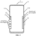
- FIG. 3 is a diagram of a structure of UE according to an exemplary embodiment.
- the UE may further include at least one pressure sensor 13.
- the at least one pressure sensor 13 may be in a one-to-one correspondence with the at least one ultrasound handprint sensor 12.
- the at least one pressure sensor may be located between a corresponding ultrasound handprint sensor 12 and the middle frame 11.
- the at least one pressure sensor may be electrically connected to the controller.
- the at least one pressure sensor 13 may be arranged for detecting a pressure applied by the hand of the user on a side wall where the corresponding ultrasound handprint sensor 12 is located.
- the controller may control, in response to the pressure detected by the at least one pressure sensor 13 exceeding a preset pressure threshold, the corresponding ultrasound handprint sensor 12 corresponding to the at least one pressure sensor 13 to acquire the electric signal of the handprint information. Accordingly, when a user is to input handprint information for unlocking, the user may apply a large force to a side wall where an ultrasound handprint sensor 12 is located. The controller may then control the ultrasound handprint sensor 12 to emit ultrasound to acquire the electric signal of the handprint information. This may prevent a user touch by accident, avoiding emitting ultrasound for acquiring the electric signal of the handprint information when the electric signal is not required.
- the controller may control the ultrasound the sensor 12 at the left bar 111 of the middle frame 11 to emit ultrasound for acquiring the electric signal of the handprint information.
- a pressure applied by a hand of a user on a side wall where an ultrasound handprint sensor corresponding to a pressure sensor is located may be detected by the pressure sensor.
- the ultrasound handprint sensor corresponding to the pressure sensor can be controlled to acquire an electric signal of handprint information, preventing a user touch by accident.
- the UE may include two ultrasound handprint sensors 12.
- the two ultrasound handprint sensors 12 may be located respectively on two opposite inner walls of the middle frame 11.
- two ultrasound handprint sensors 12 may be located respectively on two opposite inner walls of the middle frame 11.
- the user may hold the UE by hand.
- the thumb and part of the palm will be located on one side.
- the remaining four fingers will be located on the other side.
- the controller may directly control an ultrasound handprint sensor to emit ultrasound for acquiring an electric signal of handprint information.
- the user may input handprint information while holding the UE, facilitating use of handheld UE by the user.
- two ultrasound handprint sensors may be included in UE.
- the two ultrasound handprint sensors may be located respectively on two opposite inner walls of the middle frame. Accordingly, the user may input handprint information while holding the UE, enhancing user experience greatly.
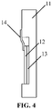
- FIG. 4 is a diagram of a sectional structure of UE according to an exemplary embodiment.
- the UE may further include a flexible board 14.
- the flexible board 14 may connect the controller to the at least one ultrasound handprint sensor.
- the flexible board may connect the at least one pressure sensor to the controller.
- an ultrasound handprint sensor and the controller may be connected by a flexible board.
- a pressure sensor and the controller may as well be connected by a flexible board.
- the flexible board may be arranged as required by a spatial layout inside UE, facilitating design of a control inside the UE.
- An engraving may be set on an outer wall of the middle frame.
- the engraving may serve to indicate an area where the at least one ultrasound handprint sensor is to acquire an electric signal of handprint information.
- the area where an ultrasound handprint sensor is to acquire an electric signal of handprint information may be an area on the outer wall on the other side of the inner wall covered by the ultrasound handprint sensor.
- various engravings may be set on the area.
- a user may learn the area where to input handprint information by touching and feeling the engraving with hand.
- an engraving may be set at the boundary of the area. Upon touching and feeling the engraving with hand, a user may learn that handprint information is to be input in the area inside the engraving.
- an engraving is set on an outer wall of the middle frame to indicate an area where the at least one ultrasound handprint sensor acquires the electric signal of the handprint information, facilitating input of the handprint information by the user at the proper location.
- the at least one ultrasound handprint sensor 12 may include a film handprint sensor.
- a groove 110 may be set on the inner wall of the middle frame 11.
- the film handprint sensor may be set inside the groove 110. Accordingly, space available to a device inside UE may be expanded.
- the film handprint sensor may be no greater in width than the inner wall of the middle frame where the film handprint sensor is located. It may be preferable that the film handprint sensor has a length that is not too long, to avoid increasing cost, or too short, to avoid difficulty in collecting a handprint. For example, the length of the film handprint sensor may be no less than 15 millimeters and no greater than 120 millimeters.
- the at least one pressure sensor 13 may include a film pressure sensor.
- a groove 110 may be set on the inner wall of the middle frame 11.
- the film handprint sensor and the film pressure sensor may be set inside the groove 110. Accordingly, space available to a device inside UE may be expanded.
- the film pressure sensor may be identical in size to the film handprint sensor. The two may overlap completely inside UE. Accordingly, the UE may directly control the ultrasound handprint sensor to collect handprint information of the pressing hand when the pressure detected by the pressure sensor exceeds a preset pressure threshold.
- FIG. 5 is a flowchart of a method for identifying a handprint according to an exemplary embodiment .
- the method for identifying a handprint may apply to any aforementioned UE.
- the method for identifying a handprint may include steps 501 to 504 as follows.
- a handprint image of a hand may be collected.
- the handprint image may include at least one of a palm print image corresponding to a palm print of a palm or a fingerprint image corresponding to a fingerprint of a finger.
- UE may control an ultrasound handprint sensor to emit ultrasound capable of passing through the middle frame, receive ultrasound reflected by a hand of a user, and generate an electric signal of handprint information according to the ultrasound reflected. Then, the UE may convert, by a controller, the electric signal of the handprint information collected by the ultrasound handprint sensor into a handprint image.
- the handprint image acquired by the UE may include at least one of a palm print image corresponding to a palm print of a palm or a fingerprint image corresponding to a fingerprint of a finger. For example, as shown in FIG. 3 , when the user holds the UE by one hand, the UE may collect fingerprint images of five fingers and the palm print image of part of the palm print.
- an image in the handprint image may be compared to a sample image in a pre-stored image library.
- the sample image in the pre-stored image library may include at least one of a palm print image corresponding to a palm print of a palm or a handprint image corresponding to a fingerprint of a finger of a legitimate user.
- UE may collect at least one of a palm print image corresponding to a palm print of a palm or a handprint image corresponding to a fingerprint of a finger of a legitimate user beforehand. Collected images may be pre-stored in an image library as sample images. Having collected the handprint image of a present user , the UE may compare an image in the handprint image to a pre-stored sample image. The UE may compute similarity between an image in the handprint image and a sample image. When similarity between two images exceeds a preset similarity threshold, it may be determined that the two images are identical. If for each image in the handprint image an identical sample image is found, it may be deemed that the handprint image is of a legitimate user. If for one image in the handprint image no identical sample image is found, it may be deemed that the handprint image is not of a legitimate user.
- step 503 when a sample image with a similarity to the image in the handprint image exceeding a preset similarity threshold is determined, a combination of hand parts corresponding to the image in the handprint image may be determined according to a pre-stored correspondence between a sample image and a hand part.
- the UE may determine a hand part corresponding to an image in the handprint image to be a hand part corresponding to a sample image identical to the image in the handprint image according to the pre-stored correspondence between a sample image and a hand part.
- the combination of hand parts corresponding to the any image in the handprint image may be determined.
- a control instruction corresponding to the combination of hand parts corresponding to the image in the handprint image may be executed according to a pre-stored correspondence between a combination of hand parts and a control instruction.
- a correspondence between a combination of hand parts and a control instruction may be pre-stored inside the UE. Accordingly, having determined a combination of hand parts corresponding to the any image in the handprint image, the UE may directly execute the control instruction corresponding to the combination of hand parts corresponding to the any image in the handprint image according to the correspondence.
- the right hand thumb corresponds to a control instruction for unlocking the UE. It may be pre-stored inside UE that a combination of the right hand thumb and an index finger corresponds to a control instruction for unlocking the UE and taking a photograph. It may be pre-stored inside UE that part of the palm and five fingers of the right hand correspond to a control instruction for unlocking an application A. It may be pre-stored inside UE that the left hand thumb corresponds to a control instruction for recording, etc.
- a user may press a handprint collecting area using the right hand thumb.
- the UE may determine that the fingerprint image is similar to a sample image of the right hand thumb of a legitimate user, and determine a hand part corresponding to the fingerprint image of the user to be the right hand thumb. Accordingly, a UE unlocking instruction may be executed to unlock the UE.
- step 501 may be implemented as step A1 to A3 as follows.
- step A1 a pressure applied by a hand of a user on a side wall where an ultrasound handprint sensor corresponding to the pressure sensor is located may be detected via the pressure sensor.
- the ultrasound handprint sensor may collect an electric signal of handprint information of the hand when the pressure exceeds a preset pressure threshold.
- step A3 the electric signal of the handprint information may be converted into a handprint image.
- At least one pressure sensor 13 may further be set on UE 1.
- the at least one pressure sensor 13 may be in a one-to-one correspondence with the at least one ultrasound handprint sensor 12.
- the at least one pressure sensor may be located between a corresponding ultrasound handprint sensor 12 and the middle frame 11.
- the at least one pressure sensor may be electrically connected to the controller.
- the at least one pressure sensor 13 may be arranged for detecting a pressure applied by the hand of the user on a side wall where the corresponding ultrasound handprint sensor 12 is located.
- the controller may control, in response to the pressure detected by the at least one pressure sensor 13 exceeding a preset pressure threshold, the corresponding ultrasound handprint sensor 12 corresponding to the at least one pressure sensor 13 to acquire the electric signal of the handprint information. Accordingly, when a user is to input handprint information for unlocking, the user may apply a large force to a side wall where an ultrasound handprint sensor 12 is located. The controller may then control the ultrasound handprint sensor 12 to emit ultrasound to acquire the electric signal of the handprint information. This may prevent a user touch by accident, avoiding emitting ultrasound for acquiring the electric signal of the handprint information when the electric signal is not required.
- a pressure applied by a hand of a user on a side wall where an ultrasound handprint sensor corresponding to a pressure sensor is located may be detected by the pressure sensor.
- the ultrasound handprint sensor corresponding to the pressure sensor can be controlled to acquire an electric signal of handprint information, preventing a user touch by accident.
- An apparatus herein as follows may be arranged for executing the method herein.
- FIG. 6 is a block diagram of an apparatus for identifying a handprint according to an exemplary embodiment, the apparatus may be implemented as part of, or entire, electronic equipment by software, hardware, or a combination of software and hardware. As shown in FIG. 6 , the apparatus for identifying a handprint may include a module as follows.
- a collecting module 601 may be arranged for collecting a handprint image of a hand.
- the handprint image may include at least one of a palm print image corresponding to a palm print of a palm or a fingerprint image corresponding to a fingerprint of a finger.
- a comparing module 602 may be arranged for comparing an image in the handprint image to a sample image in a pre-stored image library.
- a sample image in the pre-stored image library may include at least one of a palm print image corresponding to a palm print of a palm or a handprint image corresponding to a fingerprint of a finger of a legitimate user.
- a determining module 603 may be arranged for, in response to determining a sample image with a similarity to the image in the handprint image exceeding a preset similarity threshold, determining, according to a pre-stored correspondence between a sample image and a hand part, a combination of hand parts corresponding to the image in the handprint image.
- An executing module 604 may be arranged for executing, according to a pre-stored correspondence between a combination of hand parts and a control instruction, a control instruction corresponding to the combination of hand parts corresponding to the image in the handprint image.
- FIG. 7 is a block diagram of an apparatus for identifying a handprint according to an exemplary embodiment.
- the collecting module 601 may include a detecting sub-module 6011, a collecting sub-module 6012, and a converting sub-module 6013.
- the detecting sub-module 6011 may be arranged for detecting, via a pressure sensor, a pressure applied by the hand of the user on a side wall where an ultrasound handprint sensor corresponding to the pressure sensor is located.
- the collecting sub-module 6012 may be arranged for, in response to the pressure exceeding a preset pressure threshold, collecting, via the ultrasound handprint sensor, the electric signal of the handprint information of the hand.
- the converting sub-module 6013 may be arranged for converting the electric signal of the handprint information into the handprint image.
- FIG. 8 is a block diagram of an apparatus applying to UE according to an exemplary embodiment.
- the apparatus may apply to UE.
- the apparatus 800 may be a mobile phone, a game console, a computer, tablet equipment, a personal digital assistant, etc.
- the apparatus 800 may include at least one of a processing component 801, memory 802, a power supply component 803, a multimedia component 804, an audio component 805, an Input / Output (I/O) interface 806, a sensor component 807, or a communication component 808.
- the processing component 801 may generally control an overall operation of the apparatus 800, such as operations associated with display, a telephone call, data communication, a camera operation, a recording operation, etc.
- the processing component 801 may include one or more processors 820 to execute instructions so as to complete all or some steps of the method.
- the processing component 801 may include one or more modules to facilitate interaction between the processing component 801 and other components.
- the processing component 801 may include a multimedia module to facilitate interaction between the multimedia component 804 and the processing component 801.
- the memory 802 may be arranged for storing various types of data to support the operation at the apparatus 800. Examples of such data may include instructions of any application or method arranged for operating on the apparatus 800, contact data, phonebook data, messages, pictures, videos, and/or the like.
- the memory 802 may be realized by any type of transitory or non-transitory storage equipment or a combination thereof, such as Static Random Access Memory (SRAM), Electrically Erasable Programmable Read-Only Memory (EEPROM), Erasable Programmable Read-Only Memory (EPROM), Programmable Read-Only Memory (PROM), Read-Only Memory (ROM), magnetic memory, flash memory, a magnetic disk, a compact disk, etc.
- SRAM Static Random Access Memory
- EEPROM Electrically Erasable Programmable Read-Only Memory
- EPROM Erasable Programmable Read-Only Memory
- PROM Programmable Read-Only Memory
- ROM Read-Only Memory
- magnetic memory flash memory, a magnetic disk, a compact disk, etc
- the power supply component 803 may supply electric power to various components of the apparatus 800.
- the power supply component 803 may include a power management system, one or more power sources, and other components related to generating, managing, and distributing electricity for the apparatus 800.
- the multimedia component 804 may include a screen that provides an output interface between the apparatus 800 and a user.
- the screen may include a Liquid Crystal Display (LCD) and a Touch Panel (TP). If the screen includes a TP, the screen may be realized as a touch screen to receive an input signal from a user.
- the TP may include one or more touch sensors for sensing touch, slide and gestures on the TP. The one or more touch sensors not only may sense the boundary of a touch or slide move, but also detect the duration and pressure related to the touch or slide move.
- the multimedia component 804 may include a front camera and/or a rear camera. When the apparatus 800 is in an operation mode such as a shooting mode or a video mode, the front camera and/or the rear camera may receive external multimedia data. Each of the front camera and the rear camera may be a fixed optical lens system or may have a focal length and be capable of optical zooming.
- the audio component 805 may be arranged for outputting and/or inputting an audio signal.
- the audio component 805 may include a microphone (MIC).
- the MIC When the apparatus 800 is in an operation mode such as a call mode, a recording mode, a voice recognition mode, etc., the MIC may be arranged for receiving an external audio signal.
- the received audio signal may be further stored in the memory 802 or may be sent via the communication component 808.
- the audio component 805 may further include a loudspeaker arranged for outputting the audio signal.
- the I/O interface 806 may provide an interface between the processing component 801 and a peripheral interface module.
- a peripheral interface module may be a keypad, a click wheel, a button, and/or the like.
- a button may include but is not limited to at least one of: a homepage button, a volume button, a start button, or a lock button.
- the sensor component 807 may include one or more sensors for assessing various states of the apparatus 800. For example, the sensor component 807 may detect an on/off state of the apparatus 800 and relative positioning of components such as the display and the keypad of the apparatus 800. The sensor component 807 may further detect a change in the position of the apparatus 800 or of a component of the apparatus 800, whether there is contact between the apparatus 800 and a user, the orientation or acceleration/deceleration of the apparatus 800, a change in the temperature of the apparatus 800, etc.
- the sensor component 807 may include a proximity sensor arranged for detecting existence of a nearby object without physical contact.
- the sensor component 807 may further include an ultrasound handprint sensor, a pressure sensor, an optical sensor such as a Complementary Metal-Oxide-Semiconductor (CMOS) or a Charge-Coupled-Device (CCD) image sensor used in an imaging application.
- CMOS Complementary Metal-Oxide-Semiconductor
- CCD Charge-Coupled-Device
- the sensor component 807 may further include an acceleration sensor, a gyroscope sensor, a magnetic sensor, a temperature sensor, etc.
- the communication component 808 may be arranged for facilitating wired or wireless communication between the apparatus 800 and other equipment.
- the apparatus 800 may access a wireless network based on a communication standard such as Wi-Fi, 2G, 3G, ..., or a combination thereof.
- the communication component 808 may broadcast related information or receive a broadcast signal from an external broadcast management system via a broadcast channel.
- the communication component 808 may include a Near Field Communication (NFC) module for short-range communication.
- the NFC module may be based on technology such as Radio Frequency Identification (RFID), Infrared Data Association (IrDA), Ultra-Wideband (UWB) technology, Bluetooth (BT), etc.
- RFID Radio Frequency Identification
- IrDA Infrared Data Association
- UWB Ultra-Wideband
- Bluetooth Bluetooth
- the apparatus 800 may be realized by one or more electronic components such as an Application Specific Integrated Circuit (ASIC), a Digital Signal Processor (DSP), a Digital Signal Processing Device (DSPD), a Programmable Logic Device (PLD), a Field Programmable Gate Array (FPGA), a controller, a microcontroller, a microprocessor, etc., to implement the method.
- ASIC Application Specific Integrated Circuit
- DSP Digital Signal Processor
- DSPD Digital Signal Processing Device
- PLD Programmable Logic Device
- FPGA Field Programmable Gate Array
- controller a microcontroller, a microprocessor, etc.
- a non-transitory computer-readable storage medium including instructions such as memory 802 including instructions, may be provided.
- the instructions may be executed by the processor 820 of the apparatus 800 to implement the method.
- the non-transitory computer-readable storage medium may be Read-Only Memory (ROM), Compact Disc Read-Only Memory (CD-ROM), a magnetic tape, a floppy disk, optical data storage equipment, and/or the like.
- a non-transitory computer-readable storage medium may include instructions which when executed by the processor of the apparatus 800, may implement the method for identifying a handprint.
- the method may include steps as follows.
- a handprint image of a hand may be collected.
- the handprint image may include at least one of a palm print image corresponding to a palm print of a palm or a fingerprint image corresponding to a fingerprint of a finger.
- An image in the handprint image may be compared to a sample image in a pre-stored image library.
- the sample image in the pre-stored image library may include at least one of a palm print image corresponding to a palm print of a palm or a handprint image corresponding to a fingerprint of a finger of a legitimate user.
- a combination of hand parts corresponding to the image in the handprint image may be determined according to a pre-stored correspondence between a sample image and a hand part.
- a control instruction corresponding to the combination of hand parts corresponding to the image in the handprint image may be executed according to a pre-stored correspondence between a combination of hand parts and a control instruction.
- a handprint image of a hand may be collected as follows.
- a pressure applied by the hand of the user on a side wall where an ultrasound handprint sensor corresponding to the pressure sensor is located may be detected via the pressure sensor.
- the electric signal of the handprint information of the hand may be collected by the ultrasound handprint sensor when the pressure exceeds a preset pressure threshold.
- the electric signal of the handprint information may be converted into the handprint image.
- Embodiments herein further provide an apparatus for identifying a handprint.
- the apparatus may include a processor and memory for storing instructions executable by the processor.
- the processor may be arranged for executing a step as follows.
- a handprint image of a hand may be collected.
- the handprint image may include at least one of a palm print image corresponding to a palm print of a palm or a fingerprint image corresponding to a fingerprint of a finger.
- An image in the handprint image may be compared to a sample image in a pre-stored image library.
- the sample image in the pre-stored image library may include at least one of a palm print image corresponding to a palm print of a palm or a handprint image corresponding to a fingerprint of a finger of a legitimate user.
- a combination of hand parts corresponding to the image in the handprint image may be determined according to a pre-stored correspondence between a sample image and a hand part.
- a control instruction corresponding to the combination of hand parts corresponding to the image in the handprint image may be executed according to a pre-stored correspondence between a combination of hand parts and a control instruction.
- the processor may further be arranged for collecting a handprint image of a hand as follows.
- a pressure applied by the hand of the user on a side wall where an ultrasound handprint sensor corresponding to the pressure sensor is located may be detected via the pressure sensor.
- the electric signal of the handprint information of the hand may be collected by the ultrasound handprint sensor when the pressure exceeds a preset pressure threshold.
- the electric signal of the handprint information may be converted into the handprint image.
- the processor may be a Central Processing Unit (CPU), a general purpose processor, a Digital Signal Processor (DSP), an Application Specific Integrated Circuit (ASIC), and/or the like.
- a general purpose processor may be a microprocessor, any conventional processor, and/or the like.
- Aforementioned memory may be a Read-Only Memory (ROM), a Random Access Memory (RAM), a flash memory, a hard disk, a solid state disk, and/or the like.
- SIM Subscriber Identity Module
- a smart card may have to be installed on a digital mobile phone before the phone can be used.
- Content such as information on a user of the digital mobile phone, an encryption key, a phonebook of the user, may be stored on the computer chip.
- a step of the method according to any combination of embodiments herein may be executed by a hardware processor, or by a combination of hardware and software modules in the processor.
- multiple it may mean two or more.
- a term “and /or” may describe an association between associated objects, including three possible relationships.
- a and /or B it may mean that there may be three cases, namely, existence of but A, existence of both A and B, or existence of but B.
- a slash mark "/” may generally denote an "or" relationship between two associated objects that come respectively before and after the mark per se.
Landscapes
- Engineering & Computer Science (AREA)
- Physics & Mathematics (AREA)
- Theoretical Computer Science (AREA)
- General Physics & Mathematics (AREA)
- Human Computer Interaction (AREA)
- Multimedia (AREA)
- Life Sciences & Earth Sciences (AREA)
- Health & Medical Sciences (AREA)
- Data Mining & Analysis (AREA)
- Signal Processing (AREA)
- Evolutionary Computation (AREA)
- Biomedical Technology (AREA)
- Computer Vision & Pattern Recognition (AREA)
- Evolutionary Biology (AREA)
- Bioinformatics & Cheminformatics (AREA)
- General Engineering & Computer Science (AREA)
- Artificial Intelligence (AREA)
- Biophysics (AREA)
- Pathology (AREA)
- Bioinformatics & Computational Biology (AREA)
- Heart & Thoracic Surgery (AREA)
- Medical Informatics (AREA)
- Molecular Biology (AREA)
- Surgery (AREA)
- Animal Behavior & Ethology (AREA)
- General Health & Medical Sciences (AREA)
- Public Health (AREA)
- Veterinary Medicine (AREA)
- Collating Specific Patterns (AREA)
- Image Input (AREA)
Abstract
Description
- The subject disclosure relates to the field of UE technology, and in particular to UE and a method and apparatus for identifying a handprint.
- Handprint identification has become a standard on a flagship model of a mainstream mobile UE manufacturer. Handprint identification may serve not only to unlock and wake UE, etc., but also as a protective screen for data information inside the UE. With development of UE technology, there is an increasingly wide application of mobile secure payment implemented using handprint identification.
- Embodiments herein provide UE, a method and apparatus for identifying a handprint, a recording medium, and a computer program, in accordance with claims which follow.
- Other features and advantages of embodiments herein may become clear with elaboration made below, or may be learned partially by practicing embodiments herein.
- User Equipment, UE, according to a first aspect of the present invention includes a housing, at least one ultrasound handprint sensor, and a controller.
- The housing includes a front housing, a rear housing, and a middle frame. The middle frame is located between the front housing and the rear housing.
- The at least one ultrasound handprint sensor is located on an inner wall of the middle frame. The at least one ultrasound handprint sensor is arranged for emitting ultrasound capable of passing through the middle frame, receiving ultrasound reflected by a hand of a user, and generating an electric signal of handprint information according to the ultrasound reflected.
- The controller is located inside the housing. The controller is electrically connected to the at least one ultrasound handprint sensor. The controller is arranged for controlling the at least one ultrasound handprint sensor and converting the electric signal of the handprint information collected by the at least one ultrasound handprint sensor into a handprint image.
- As the UE can collect a handprint by ultrasound, no opening has to be made on the UE to reveal any handprint collecting area. Thus, such a handprint collecting module can be hidden completely inside the housing, improving integrity of UE design and overall look of the machine, reducing a number of openings, reducing cost and difficulty in manufacturing a housing.
- The UE may further include at least one pressure sensor.
- The at least one pressure sensor may be in a one-to-one correspondence with the at least one ultrasound handprint sensor. The at least one pressure sensor may be located between a corresponding ultrasound handprint sensor and the middle frame. The at least one pressure sensor may be electrically connected to the controller. The at least one pressure sensor may be arranged for detecting a pressure applied by the hand of the user on a side wall where the corresponding ultrasound handprint sensor is located.
- The controller may be arranged for controlling, in response to the pressure detected by the at least one pressure sensor exceeding a preset pressure threshold, the corresponding ultrasound handprint sensor corresponding to the at least one pressure sensor to acquire the electric signal of the handprint information.
- Accordingly, when a user is to input handprint information for unlocking, the user may apply a large force to a side wall where an ultrasound handprint sensor is located. The controller may then control the ultrasound handprint sensor to emit ultrasound to acquire the electric signal of the handprint information. This may prevent a user touch by accident, avoiding emitting ultrasound for acquiring the electric signal of the handprint information when the electric signal is not required.
- The at least one ultrasound handprint sensor may include two ultrasound handprint sensors.
- The two ultrasound handprint sensors may be located respectively on two opposite inner walls of the middle frame.
- Two ultrasound handprint sensors may be located respectively on two opposite inner walls of the middle frame. The user may hold the UE by hand. The thumb and part of the palm will be located on one side. The remaining four fingers will be located on the other side. Then, to acquire a handprint image, the controller may directly control an ultrasound handprint sensor to emit ultrasound for acquiring an electric signal of handprint information. The user may input handprint information while holding the UE, facilitating use of handheld UE by the user.
- Two ultrasound handprint sensors may be included in UE. The two ultrasound handprint sensors may be located respectively on two opposite inner walls of the middle frame. Accordingly, the user may input handprint information while holding the UE, enhancing user experience greatly.
- The UE may further include a flexible board.
- The flexible board may connect the controller to the at least one ultrasound handprint sensor. The flexible board may connect the at least one pressure sensor to the controller.
- An ultrasound handprint sensor and the controller may be connected by a flexible board. A pressure sensor and the controller may as well be connected by a flexible board. As a flexible board is free to bend, coil, fold, etc., the flexible board may be arranged as required by a spatial layout inside UE, facilitating design of a control inside the UE.
- An engraving may be set on an outer wall of the middle frame. The engraving may indicate an area where the at least one ultrasound handprint sensor acquires the electric signal of the handprint information.
- An engraving is set on an outer wall of the middle frame to indicate an area where the at least one ultrasound handprint sensor acquires the electric signal of the handprint information, facilitating input of the handprint information by the user at the proper location.
- The at least one ultrasound handprint sensor may include a film handprint sensor. A groove may be set on the inner wall of the middle frame. The film handprint sensor may be set inside the groove.
- Accordingly, space available to a device inside UE may be expanded.
- The at least one pressure sensor may include a film pressure sensor. A groove may be set on the inner wall of the middle frame. The film handprint sensor and the film pressure sensor may be set inside the groove. The film pressure sensor may be identical in size to the film handprint sensor.
- Accordingly, space available to a device inside UE may be expanded.
- A method for identifying a handprint according to a second aspect of the present invention is disclosed, which especially can be adapted to be used with the UE of the invention.
- The method includes collecting the handprint image of the hand. The handprint image includes at least one of a palm print image corresponding to a palm print of a palm or a fingerprint image corresponding to a fingerprint of a finger.
- The method includes comparing an image in the handprint image to a sample image in a pre-stored image library. The sample image in the pre-stored image library includes at least one of a palm print image corresponding to a palm print of a palm or a handprint image corresponding to a fingerprint of a finger of a legitimate user.
- The method includes: in response to determining a sample image with a similarity to the image in the handprint image exceeding a preset similarity threshold, determining, according to a pre-stored correspondence between a sample image and a hand part, a combination of hand parts corresponding to the image in the handprint image.
- The method includes executing, according to a pre-stored correspondence between a combination of hand parts and a control instruction, a control instruction corresponding to the combination of hand parts corresponding to the image in the handprint image.
- A correspondence between a combination of hand parts and a control instruction, default in UE or as set by a user, may be pre-stored inside the UE. Accordingly, having determined a combination of hand parts corresponding to the any image in the handprint image, the UE may directly execute the control instruction corresponding to the combination of hand parts corresponding to the any image in the handprint image according to the correspondence.
- When the UE includes a pressure sensor, the collecting the handprint image of the hand may include:
- detecting, via the pressure sensor, a pressure applied by the hand of the user on a side wall where an ultrasound handprint sensor corresponding to the pressure sensor is located;
- in response to the pressure exceeding a preset pressure threshold, collecting, by the ultrasound handprint sensor, the electric signal of the handprint information of the hand; and
- converting the electric signal of the handprint information into the handprint image.
- Accordingly, when a user is to input handprint information for unlocking, the user may apply a large force to a side wall where an ultrasound handprint sensor is located. The controller may then control the ultrasound handprint sensor to emit ultrasound to acquire the electric signal of the handprint information. This may prevent a user touch by accident, avoiding emitting ultrasound for acquiring the electric signal of the handprint information when the electric signal is not required.
- An apparatus for identifying a handprint according to a third aspect of the present invention is disclosed, which especially can be used with the UE of the invention applies to the UE. The apparatus includes modules as follows.
- A collecting module is arranged for collecting the handprint image of the hand. The handprint image includes at least one of a palm print image corresponding to a palm print of a palm or a fingerprint image corresponding to a fingerprint of a finger.
- A comparing module is arranged for comparing an image in the handprint image to a sample image in a pre-stored image library. The sample image in the pre-stored image library includes at least one of a palm print image corresponding to a palm print of a palm or a handprint image corresponding to a fingerprint of a finger of a legitimate user.
- A determining module is arranged for, in response to determining a sample image with a similarity to the image in the handprint image exceeding a preset similarity threshold, determining, according to a pre-stored correspondence between a sample image and a hand part, a combination of hand parts corresponding to the image in the handprint image.
- An executing module is arranged for executing, according to a pre-stored correspondence between a combination of hand parts and a control instruction, a control instruction corresponding to the combination of hand parts corresponding to the image in the handprint image.
- The advantages and technical effects of the apparatus herein correspond to those of the method presented above.
- When the UE includes a pressure sensor, the collecting module may include:
- a detecting sub-module arranged for detecting, via the pressure sensor, a pressure applied by the hand of the user on a side wall where an ultrasound handprint sensor corresponding to the pressure sensor is located;
- a collecting sub-module arranged for, in response to the pressure exceeding a preset pressure threshold, collecting, via the ultrasound handprint sensor, the electric signal of the handprint information of the hand; and
- a converting sub-module arranged for converting the electric signal of the handprint information into the handprint image.
- An apparatus for identifying a handprint according to a fourth aspect of the present invention is disclosed, which can especially be adapted for use with the UE of the invention. The apparatus includes a processor and memory for storing instructions executable by the processor.
- The processor is arranged for executing a step of the method.
- The steps of the method may be determined by computer program instructions.
- Consequently, according to a fifth aspect of the present invention, the subject disclosure is further directed to a computer program for executing the steps of the method as described above when this program is executed by a computer.
- This program can use any programming language and take the form of source code, object code or a code intermediate between source code and object code, such as a partially compiled form, or any other desirable form.
- According to a sixth aspect of the present invention, the subject disclosure is further directed to a computer-readable information medium containing instructions of a computer program as described above.
- The information medium can be any entity or device capable of storing the program. For example, the support can include storage means such as a ROM, for example a CD ROM or a microelectronic circuit ROM, or magnetic storage means, for example a diskette (floppy disk) or a hard disk.
- Alternatively, the information medium can be an integrated circuit in which the program is incorporated, the circuit being adapted to execute the method in question or to be used in its execution.
- The above general description and elaboration below are but exemplary and explanatory, and do not limit the subject disclosure.
- A drawing here is incorporated in the subject disclosure, constitutes part of the subject disclosure, illustrates at least one embodiment according to the subject disclosure, and together with the subject disclosure, serves to explain the principle of the subject disclosure.
-
FIG. 1 is a diagram of a structure of UE according to an exemplary embodiment. -
FIG. 2 is a diagram of a structure of UE according to an exemplary embodiment. -
FIG. 3 is a diagram of a structure of UE according to an exemplary embodiment. -
FIG. 4 is a diagram of a structure of UE according to an exemplary embodiment. -
FIG. 5 is a flowchart of a method for identifying a handprint according to an exemplary embodiment. -
FIG. 6 is a block diagram of an apparatus for identifying a handprint according to an exemplary embodiment. -
FIG. 7 is a block diagram of an apparatus for identifying a handprint according to an exemplary embodiment. -
FIG. 8 is a block diagram of an apparatus for identifying a handprint according to an exemplary embodiment. - Exemplary embodiments (examples of which are illustrated in the accompanying drawings) are elaborated below. The following description refers to the accompanying drawings, in which identical or similar elements in two drawings are denoted by identical reference numerals unless indicated otherwise. The exemplary implementation modes may take on multiple forms, and should not be taken as being limited to examples illustrated herein. Instead, by providing such implementation modes, embodiments herein may become more comprehensive and complete, and comprehensive concept of the exemplary implementation modes may be delivered to those skilled in the art. Implementations set forth in the following exemplary embodiments do not represent all implementations in accordance with the subject disclosure. Rather, they are merely examples of the apparatus and method in accordance with certain aspects herein as recited in the accompanying claims.
- A term used in an embodiment herein is merely for describing the embodiment instead of limiting the subject disclosure. A singular form "a" and "the" used in an embodiment herein and the appended claims may also be intended to include a plural form, unless clearly indicated otherwise by context. Further note that a term "and /or" used herein may refer to and contain any combination or all possible combinations of one or more associated listed items.
- Note that although a term such as first, second, third may be adopted in an embodiment herein to describe various kinds of information, such information should not be limited to such a term. Such a term is merely for distinguishing information of the same type. For example, without departing from the scope of the embodiments herein, the first information may also be referred to as the second information. Similarly, the second information may also be referred to as the first information. Depending on the context, a "if' as used herein may be interpreted as "when" or "while" or "in response to determining that".
- In addition, described characteristics, structures or features may be combined in one or more implementation modes in any proper manner. In the following descriptions, many details are provided to allow a full understanding of embodiments herein. However, those skilled in the art will know that the technical solutions of embodiments herein may be carried out without one or more of the details; alternatively, another method, component, device, step, etc. may be adopted. Under other conditions, no detail of a known structure, method, device, implementation, material or operation may be shown or described to avoid obscuring aspects of embodiments herein.
- A block diagram shown in the accompanying drawings may be a functional entity which may not necessarily correspond to a physically or logically independent entity. Such a functional entity may be implemented in form of software, in one or more hardware modules or integrated circuits, or in different networks and /or processor devices and /or microcontroller devices.
- An existing fingerprint module arranged for identifying a fingerprint in general may be set at a bottom area of a front housing of UE. An opening may have to be made at the bottom area, to reveal a handprint collecting area of the handprint module, such that a user may input a handprint in the handprint collecting area. The opening in general may be large, increasing difficulty in manufacturing a housing, increasing a manufacturing cost. Plus, reveal of the handprint collecting area may not look good.
- In view of this, at least one embodiment herein provides UE. The UE may include a housing. The housing may include a front housing. The housing may include a rear housing. The housing may include a middle frame. The middle frame may be located between the front housing and the rear housing. The UE may include at least one ultrasound handprint sensor. The at least one ultrasound handprint sensor may be located on an inner wall of the middle frame. The at least one ultrasound handprint sensor may be arranged for emitting ultrasound capable of passing through the middle frame. The at least one ultrasound handprint sensor may be arranged for receiving ultrasound reflected by a hand of a user. The at least one ultrasound handprint sensor may be arranged for generating an electric signal of handprint information according to the ultrasound reflected. The UE may include a controller. The controller may be located inside the housing. The controller may be electrically connected to the at least one ultrasound handprint sensor. The controller may be arranged for controlling the at least one ultrasound handprint sensor. The controller may be arranged for converting the electric signal of the handprint information collected by the at least one ultrasound handprint sensor into a handprint image. As the UE can collect a handprint by ultrasound, no opening has to be made on the UE to reveal any handprint collecting area. Thus, such a handprint collecting module can be hidden completely inside the housing, improving integrity of UE design and overall look of the machine, reducing a number of openings, reducing cost and difficulty in manufacturing a housing.
-
FIG. 1 is a diagram of a structure of UE according to an exemplary embodiment. As shown inFIG. 1 , theUE 1 may include a housing. The housing may include a front housing, a rear housing (not shown in the drawing), and amiddle frame 11 located between the front housing and the rear housing. For example, the UE may be a mobile phone. The front housing may be a protective housing located on a display module of the UE. The rear housing may be a rear cover for a battery of the UE. The middle frame may be a rectangular frame surrounded by four side walls of the UE. The middle frame may connect edges of the rear housing and of the front housing. The middle frame may form, together with the front housing and the rear housing, the housing of the UE. - As shown in
FIG. 1 , theUE 1 may further include at least oneultrasound handprint sensor 12. The at least oneultrasound handprint sensor 12 may be located on an inner wall of themiddle frame 11. The inner wall may refer to a side on themiddle frame 11 that faces the interior of the UE. The middle frame on the UE in general may include four bars in a circle, such as a top bar located at the top of the UE, a bottom bar located at the bottom of the UE, and a left bar and a right bar located respectively on the left side and on the right side of the UE. For example, as shown inFIG. 1 , the UE may include oneultrasound handprint sensor 12. The oneultrasound handprint sensor 12 may be located on the inner wall of theleft bar 111 of themiddle frame 11. For example,FIG. 2 is a diagram of a structure of UE according to an exemplary embodiment. As shown inFIG. 2 , the UE may include twoultrasound handprint sensors 12, oneultrasound handprint sensor 12 located on the inner wall of theleft bar 111 of themiddle frame 11, the otherultrasound handprint sensor 12 located on the inner wall of theright bar 112 of themiddle frame 11. The ultrasound handprint sensor may as well be set on another bar of themiddle frame 11, or on any available area on the middle frame, which is not limited here. An available area of themiddle frame 11 may refer to an area on the middle frame other than where a button, various openings such as an opening for a microphone, a USB interface, etc., are set. - The
UE 1 may further include a controller (not shown in the drawing). The controller may be located inside the housing of the UE. The controller may be electrically connected to the at least one ultrasound handprint sensor 101. The controller may be arranged for controlling the at least one ultrasound handprint sensor. For example, when a handprint image of a user is to be acquired to identify the user such as for unlocking, the controller may control the at least one ultrasound handprint sensor to emit ultrasound to acquire the electric signal of the handprint information, etc. The controller may convert the electric signal of the handprint information collected by the at least one ultrasound handprint sensor into a handprint image. Then, the user may be identified according to the handprint image, or different instructions may be executed according to different handprint images. - Here, as a handprint image may be acquired by ultrasound, no opening has to be made on the UE to reveal any handprint collecting area. Thus, such a handprint collecting module can be hidden completely inside the housing, improving integrity of UE design and overall look of the machine, reducing a number of openings, reducing cost and difficulty in manufacturing a housing.
-
FIG. 3 is a diagram of a structure of UE according to an exemplary embodiment. As shown inFIG. 3 , the UE may further include at least onepressure sensor 13. As shown inFIG. 3 , the at least onepressure sensor 13 may be in a one-to-one correspondence with the at least oneultrasound handprint sensor 12. The at least one pressure sensor may be located between a correspondingultrasound handprint sensor 12 and themiddle frame 11. The at least one pressure sensor may be electrically connected to the controller. The at least onepressure sensor 13 may be arranged for detecting a pressure applied by the hand of the user on a side wall where the correspondingultrasound handprint sensor 12 is located. Thus, the controller may control, in response to the pressure detected by the at least onepressure sensor 13 exceeding a preset pressure threshold, the correspondingultrasound handprint sensor 12 corresponding to the at least onepressure sensor 13 to acquire the electric signal of the handprint information. Accordingly, when a user is to input handprint information for unlocking, the user may apply a large force to a side wall where anultrasound handprint sensor 12 is located. The controller may then control theultrasound handprint sensor 12 to emit ultrasound to acquire the electric signal of the handprint information. This may prevent a user touch by accident, avoiding emitting ultrasound for acquiring the electric signal of the handprint information when the electric signal is not required. - For example, as shown in
FIG. 3 , if thepressure sensor 13 at theleft bar 111 of themiddle frame 11 has detected a pressure exceeding the preset pressure threshold, the controller may control the ultrasound thesensor 12 at theleft bar 111 of themiddle frame 11 to emit ultrasound for acquiring the electric signal of the handprint information. - Here, a pressure applied by a hand of a user on a side wall where an ultrasound handprint sensor corresponding to a pressure sensor is located may be detected by the pressure sensor. When the pressure detected by the pressure sensor exceeds a preset pressure threshold, the ultrasound handprint sensor corresponding to the pressure sensor can be controlled to acquire an electric signal of handprint information, preventing a user touch by accident.
- As shown in
FIG. 2 orFIG. 3 , the UE may include twoultrasound handprint sensors 12. The twoultrasound handprint sensors 12 may be located respectively on two opposite inner walls of themiddle frame 11. - For example, as shown in
FIG. 3 , twoultrasound handprint sensors 12 may be located respectively on two opposite inner walls of themiddle frame 11. The user may hold the UE by hand. The thumb and part of the palm will be located on one side. The remaining four fingers will be located on the other side. Then, to acquire a handprint image, the controller may directly control an ultrasound handprint sensor to emit ultrasound for acquiring an electric signal of handprint information. The user may input handprint information while holding the UE, facilitating use of handheld UE by the user. - Here, two ultrasound handprint sensors may be included in UE. The two ultrasound handprint sensors may be located respectively on two opposite inner walls of the middle frame. Accordingly, the user may input handprint information while holding the UE, enhancing user experience greatly.
-
FIG. 4 is a diagram of a sectional structure of UE according to an exemplary embodiment. As shown inFIG. 4 , the UE may further include aflexible board 14. Theflexible board 14 may connect the controller to the at least one ultrasound handprint sensor. The flexible board may connect the at least one pressure sensor to the controller. - Here, an ultrasound handprint sensor and the controller may be connected by a flexible board. A pressure sensor and the controller may as well be connected by a flexible board. As a flexible board is free to bend, coil, fold, etc., the flexible board may be arranged as required by a spatial layout inside UE, facilitating design of a control inside the UE.
- An engraving may be set on an outer wall of the middle frame. The engraving may serve to indicate an area where the at least one ultrasound handprint sensor is to acquire an electric signal of handprint information.
- The area where an ultrasound handprint sensor is to acquire an electric signal of handprint information may be an area on the outer wall on the other side of the inner wall covered by the ultrasound handprint sensor. For example, various engravings may be set on the area. A user may learn the area where to input handprint information by touching and feeling the engraving with hand. Or, an engraving may be set at the boundary of the area. Upon touching and feeling the engraving with hand, a user may learn that handprint information is to be input in the area inside the engraving.
- Here, an engraving is set on an outer wall of the middle frame to indicate an area where the at least one ultrasound handprint sensor acquires the electric signal of the handprint information, facilitating input of the handprint information by the user at the proper location.
- As shown in
FIG. 4 , the at least oneultrasound handprint sensor 12 may include a film handprint sensor. A groove 110 may be set on the inner wall of themiddle frame 11. The film handprint sensor may be set inside the groove 110. Accordingly, space available to a device inside UE may be expanded. - The film handprint sensor may be no greater in width than the inner wall of the middle frame where the film handprint sensor is located. It may be preferable that the film handprint sensor has a length that is not too long, to avoid increasing cost, or too short, to avoid difficulty in collecting a handprint. For example, the length of the film handprint sensor may be no less than 15 millimeters and no greater than 120 millimeters.
- As shown in
FIG. 4 , the at least onepressure sensor 13 may include a film pressure sensor. A groove 110 may be set on the inner wall of themiddle frame 11. The film handprint sensor and the film pressure sensor may be set inside the groove 110. Accordingly, space available to a device inside UE may be expanded. - The film pressure sensor may be identical in size to the film handprint sensor. The two may overlap completely inside UE. Accordingly, the UE may directly control the ultrasound handprint sensor to collect handprint information of the pressing hand when the pressure detected by the pressure sensor exceeds a preset pressure threshold.
- Embodiments herein further provide a method for identifying a handprint.
FIG. 5 is a flowchart of a method for identifying a handprint according to an exemplary embodiment . The method for identifying a handprint may apply to any aforementioned UE. As shown inFIG. 5 , the method for identifying a handprint may includesteps 501 to 504 as follows. - In
step 501, a handprint image of a hand may be collected. The handprint image may include at least one of a palm print image corresponding to a palm print of a palm or a fingerprint image corresponding to a fingerprint of a finger. - To collect handprint information, UE may control an ultrasound handprint sensor to emit ultrasound capable of passing through the middle frame, receive ultrasound reflected by a hand of a user, and generate an electric signal of handprint information according to the ultrasound reflected. Then, the UE may convert, by a controller, the electric signal of the handprint information collected by the ultrasound handprint sensor into a handprint image. The handprint image acquired by the UE may include at least one of a palm print image corresponding to a palm print of a palm or a fingerprint image corresponding to a fingerprint of a finger. For example, as shown in
FIG. 3 , when the user holds the UE by one hand, the UE may collect fingerprint images of five fingers and the palm print image of part of the palm print. - In
step 502, an image in the handprint image may be compared to a sample image in a pre-stored image library. The sample image in the pre-stored image library may include at least one of a palm print image corresponding to a palm print of a palm or a handprint image corresponding to a fingerprint of a finger of a legitimate user. - UE may collect at least one of a palm print image corresponding to a palm print of a palm or a handprint image corresponding to a fingerprint of a finger of a legitimate user beforehand. Collected images may be pre-stored in an image library as sample images. Having collected the handprint image of a present user, the UE may compare an image in the handprint image to a pre-stored sample image. The UE may compute similarity between an image in the handprint image and a sample image. When similarity between two images exceeds a preset similarity threshold, it may be determined that the two images are identical. If for each image in the handprint image an identical sample image is found, it may be deemed that the handprint image is of a legitimate user. If for one image in the handprint image no identical sample image is found, it may be deemed that the handprint image is not of a legitimate user.

- In
step 503, when a sample image with a similarity to the image in the handprint image exceeding a preset similarity threshold is determined, a combination of hand parts corresponding to the image in the handprint image may be determined according to a pre-stored correspondence between a sample image and a hand part. - When for each image in the handprint image a sample image with a similarity to the each image exceeding a preset similarity threshold is found, it means for each image in the handprint image an identical sample image is found, and it may be deemed that the handprint image is of a legitimate user. Then, the UE may determine a hand part corresponding to an image in the handprint image to be a hand part corresponding to a sample image identical to the image in the handprint image according to the pre-stored correspondence between a sample image and a hand part. Thus, the combination of hand parts corresponding to the any image in the handprint image may be determined.
- In
step 504, a control instruction corresponding to the combination of hand parts corresponding to the image in the handprint image may be executed according to a pre-stored correspondence between a combination of hand parts and a control instruction. - A correspondence between a combination of hand parts and a control instruction, default in UE or as set by a user, may be pre-stored inside the UE. Accordingly, having determined a combination of hand parts corresponding to the any image in the handprint image, the UE may directly execute the control instruction corresponding to the combination of hand parts corresponding to the any image in the handprint image according to the correspondence.
- For example, it may be pre-stored inside UE that the right hand thumb corresponds to a control instruction for unlocking the UE. It may be pre-stored inside UE that a combination of the right hand thumb and an index finger corresponds to a control instruction for unlocking the UE and taking a photograph. It may be pre-stored inside UE that part of the palm and five fingers of the right hand correspond to a control instruction for unlocking an application A. It may be pre-stored inside UE that the left hand thumb corresponds to a control instruction for recording, etc. Thus, to unlock UE, a user may press a handprint collecting area using the right hand thumb. Having collected a fingerprint image of the right hand thumb of the user, the UE may determine that the fingerprint image is similar to a sample image of the right hand thumb of a legitimate user, and determine a hand part corresponding to the fingerprint image of the user to be the right hand thumb. Accordingly, a UE unlocking instruction may be executed to unlock the UE.
- When the UE includes a pressure sensor, the
step 501 may be implemented as step A1 to A3 as follows. - In step A1, a pressure applied by a hand of a user on a side wall where an ultrasound handprint sensor corresponding to the pressure sensor is located may be detected via the pressure sensor.
- In step A2, the ultrasound handprint sensor may collect an electric signal of handprint information of the hand when the pressure exceeds a preset pressure threshold.
- In step A3, the electric signal of the handprint information may be converted into a handprint image.
- To prevent a user touch by accident, as shown in
FIG. 3 , at least onepressure sensor 13 may further be set onUE 1. The at least onepressure sensor 13 may be in a one-to-one correspondence with the at least oneultrasound handprint sensor 12. The at least one pressure sensor may be located between a correspondingultrasound handprint sensor 12 and themiddle frame 11. The at least one pressure sensor may be electrically connected to the controller. The at least onepressure sensor 13 may be arranged for detecting a pressure applied by the hand of the user on a side wall where the correspondingultrasound handprint sensor 12 is located. Thus, the controller may control, in response to the pressure detected by the at least onepressure sensor 13 exceeding a preset pressure threshold, the correspondingultrasound handprint sensor 12 corresponding to the at least onepressure sensor 13 to acquire the electric signal of the handprint information. Accordingly, when a user is to input handprint information for unlocking, the user may apply a large force to a side wall where anultrasound handprint sensor 12 is located. The controller may then control theultrasound handprint sensor 12 to emit ultrasound to acquire the electric signal of the handprint information. This may prevent a user touch by accident, avoiding emitting ultrasound for acquiring the electric signal of the handprint information when the electric signal is not required. - Here, a pressure applied by a hand of a user on a side wall where an ultrasound handprint sensor corresponding to a pressure sensor is located may be detected by the pressure sensor. When the pressure detected by the pressure sensor exceeds a preset pressure threshold, the ultrasound handprint sensor corresponding to the pressure sensor can be controlled to acquire an electric signal of handprint information, preventing a user touch by accident.
- An apparatus herein as follows may be arranged for executing the method herein.
-
FIG. 6 is a block diagram of an apparatus for identifying a handprint according to an exemplary embodiment, the apparatus may be implemented as part of, or entire, electronic equipment by software, hardware, or a combination of software and hardware. As shown inFIG. 6 , the apparatus for identifying a handprint may include a module as follows. - A collecting
module 601 may be arranged for collecting a handprint image of a hand. The handprint image may include at least one of a palm print image corresponding to a palm print of a palm or a fingerprint image corresponding to a fingerprint of a finger. - A comparing
module 602 may be arranged for comparing an image in the handprint image to a sample image in a pre-stored image library. A sample image in the pre-stored image library may include at least one of a palm print image corresponding to a palm print of a palm or a handprint image corresponding to a fingerprint of a finger of a legitimate user. - A determining
module 603 may be arranged for, in response to determining a sample image with a similarity to the image in the handprint image exceeding a preset similarity threshold, determining, according to a pre-stored correspondence between a sample image and a hand part, a combination of hand parts corresponding to the image in the handprint image. - An executing
module 604 may be arranged for executing, according to a pre-stored correspondence between a combination of hand parts and a control instruction, a control instruction corresponding to the combination of hand parts corresponding to the image in the handprint image. -
FIG. 7 is a block diagram of an apparatus for identifying a handprint according to an exemplary embodiment. As shown inFIG. 7 , the collectingmodule 601 may include a detecting sub-module 6011, a collecting sub-module 6012, and a converting sub-module 6013. - The detecting sub-module 6011 may be arranged for detecting, via a pressure sensor, a pressure applied by the hand of the user on a side wall where an ultrasound handprint sensor corresponding to the pressure sensor is located.
- The collecting sub-module 6012 may be arranged for, in response to the pressure exceeding a preset pressure threshold, collecting, via the ultrasound handprint sensor, the electric signal of the handprint information of the hand.
- The converting sub-module 6013 may be arranged for converting the electric signal of the handprint information into the handprint image.
- Refer to a method herein for elaboration of how a module of the apparatus executes an operation, which is not repeated here.
-
FIG. 8 is a block diagram of an apparatus applying to UE according to an exemplary embodiment. The apparatus may apply to UE. For example, theapparatus 800 may be a mobile phone, a game console, a computer, tablet equipment, a personal digital assistant, etc. - The
apparatus 800 may include at least one of aprocessing component 801,memory 802, apower supply component 803, amultimedia component 804, anaudio component 805, an Input / Output (I/O)interface 806, asensor component 807, or acommunication component 808. - The
processing component 801 may generally control an overall operation of theapparatus 800, such as operations associated with display, a telephone call, data communication, a camera operation, a recording operation, etc. Theprocessing component 801 may include one ormore processors 820 to execute instructions so as to complete all or some steps of the method. In addition, theprocessing component 801 may include one or more modules to facilitate interaction between theprocessing component 801 and other components. For example, theprocessing component 801 may include a multimedia module to facilitate interaction between themultimedia component 804 and theprocessing component 801. - The
memory 802 may be arranged for storing various types of data to support the operation at theapparatus 800. Examples of such data may include instructions of any application or method arranged for operating on theapparatus 800, contact data, phonebook data, messages, pictures, videos, and/or the like. Thememory 802 may be realized by any type of transitory or non-transitory storage equipment or a combination thereof, such as Static Random Access Memory (SRAM), Electrically Erasable Programmable Read-Only Memory (EEPROM), Erasable Programmable Read-Only Memory (EPROM), Programmable Read-Only Memory (PROM), Read-Only Memory (ROM), magnetic memory, flash memory, a magnetic disk, a compact disk, etc. - The
power supply component 803 may supply electric power to various components of theapparatus 800. Thepower supply component 803 may include a power management system, one or more power sources, and other components related to generating, managing, and distributing electricity for theapparatus 800. - The
multimedia component 804 may include a screen that provides an output interface between theapparatus 800 and a user. The screen may include a Liquid Crystal Display (LCD) and a Touch Panel (TP). If the screen includes a TP, the screen may be realized as a touch screen to receive an input signal from a user. The TP may include one or more touch sensors for sensing touch, slide and gestures on the TP. The one or more touch sensors not only may sense the boundary of a touch or slide move, but also detect the duration and pressure related to the touch or slide move. Themultimedia component 804 may include a front camera and/or a rear camera. When theapparatus 800 is in an operation mode such as a shooting mode or a video mode, the front camera and/or the rear camera may receive external multimedia data. Each of the front camera and the rear camera may be a fixed optical lens system or may have a focal length and be capable of optical zooming. - The
audio component 805 may be arranged for outputting and/or inputting an audio signal. For example, theaudio component 805 may include a microphone (MIC). When theapparatus 800 is in an operation mode such as a call mode, a recording mode, a voice recognition mode, etc., the MIC may be arranged for receiving an external audio signal. The received audio signal may be further stored in thememory 802 or may be sent via thecommunication component 808. Theaudio component 805 may further include a loudspeaker arranged for outputting the audio signal. - The I/
O interface 806 may provide an interface between theprocessing component 801 and a peripheral interface module. Such a peripheral interface module may be a keypad, a click wheel, a button, and/or the like. Such a button may include but is not limited to at least one of: a homepage button, a volume button, a start button, or a lock button. - The
sensor component 807 may include one or more sensors for assessing various states of theapparatus 800. For example, thesensor component 807 may detect an on/off state of theapparatus 800 and relative positioning of components such as the display and the keypad of theapparatus 800. Thesensor component 807 may further detect a change in the position of theapparatus 800 or of a component of theapparatus 800, whether there is contact between theapparatus 800 and a user, the orientation or acceleration/deceleration of theapparatus 800, a change in the temperature of theapparatus 800, etc. Thesensor component 807 may include a proximity sensor arranged for detecting existence of a nearby object without physical contact. Thesensor component 807 may further include an ultrasound handprint sensor, a pressure sensor, an optical sensor such as a Complementary Metal-Oxide-Semiconductor (CMOS) or a Charge-Coupled-Device (CCD) image sensor used in an imaging application. In some embodiments, thesensor component 807 may further include an acceleration sensor, a gyroscope sensor, a magnetic sensor, a temperature sensor, etc. - The
communication component 808 may be arranged for facilitating wired or wireless communication between theapparatus 800 and other equipment. Theapparatus 800 may access a wireless network based on a communication standard such as Wi-Fi, 2G, 3G, ..., or a combination thereof. Thecommunication component 808 may broadcast related information or receive a broadcast signal from an external broadcast management system via a broadcast channel. Thecommunication component 808 may include a Near Field Communication (NFC) module for short-range communication. For example, the NFC module may be based on technology such as Radio Frequency Identification (RFID), Infrared Data Association (IrDA), Ultra-Wideband (UWB) technology, Bluetooth (BT), etc. - The
apparatus 800 may be realized by one or more electronic components such as an Application Specific Integrated Circuit (ASIC), a Digital Signal Processor (DSP), a Digital Signal Processing Device (DSPD), a Programmable Logic Device (PLD), a Field Programmable Gate Array (FPGA), a controller, a microcontroller, a microprocessor, etc., to implement the method. - A non-transitory computer-readable storage medium including instructions, such as
memory 802 including instructions, may be provided. The instructions may be executed by theprocessor 820 of theapparatus 800 to implement the method. For example, the non-transitory computer-readable storage medium may be Read-Only Memory (ROM), Compact Disc Read-Only Memory (CD-ROM), a magnetic tape, a floppy disk, optical data storage equipment, and/or the like. - A non-transitory computer-readable storage medium may include instructions which when executed by the processor of the
apparatus 800, may implement the method for identifying a handprint. The method may include steps as follows. - A handprint image of a hand may be collected. The handprint image may include at least one of a palm print image corresponding to a palm print of a palm or a fingerprint image corresponding to a fingerprint of a finger.
- An image in the handprint image may be compared to a sample image in a pre-stored image library. The sample image in the pre-stored image library may include at least one of a palm print image corresponding to a palm print of a palm or a handprint image corresponding to a fingerprint of a finger of a legitimate user.
- When a sample image with a similarity to the image in the handprint image exceeding a preset similarity threshold is found, a combination of hand parts corresponding to the image in the handprint image may be determined according to a pre-stored correspondence between a sample image and a hand part.
- A control instruction corresponding to the combination of hand parts corresponding to the image in the handprint image may be executed according to a pre-stored correspondence between a combination of hand parts and a control instruction.
- When the UE includes a pressure sensor, a handprint image of a hand may be collected as follows.
- A pressure applied by the hand of the user on a side wall where an ultrasound handprint sensor corresponding to the pressure sensor is located may be detected via the pressure sensor.
- The electric signal of the handprint information of the hand may be collected by the ultrasound handprint sensor when the pressure exceeds a preset pressure threshold.
- The electric signal of the handprint information may be converted into the handprint image.
- Embodiments herein further provide an apparatus for identifying a handprint. The apparatus may include a processor and memory for storing instructions executable by the processor.
- The processor may be arranged for executing a step as follows.
- A handprint image of a hand may be collected. The handprint image may include at least one of a palm print image corresponding to a palm print of a palm or a fingerprint image corresponding to a fingerprint of a finger.
- An image in the handprint image may be compared to a sample image in a pre-stored image library. The sample image in the pre-stored image library may include at least one of a palm print image corresponding to a palm print of a palm or a handprint image corresponding to a fingerprint of a finger of a legitimate user.
- When a sample image with a similarity to the image in the handprint image exceeding a preset similarity threshold is found, a combination of hand parts corresponding to the image in the handprint image may be determined according to a pre-stored correspondence between a sample image and a hand part.
- A control instruction corresponding to the combination of hand parts corresponding to the image in the handprint image may be executed according to a pre-stored correspondence between a combination of hand parts and a control instruction.
- When the UE includes a pressure sensor, the processor may further be arranged for collecting a handprint image of a hand as follows.
- A pressure applied by the hand of the user on a side wall where an ultrasound handprint sensor corresponding to the pressure sensor is located may be detected via the pressure sensor.
- The electric signal of the handprint information of the hand may be collected by the ultrasound handprint sensor when the pressure exceeds a preset pressure threshold.
- The electric signal of the handprint information may be converted into the handprint image.
- The processor may be a Central Processing Unit (CPU), a general purpose processor, a Digital Signal Processor (DSP), an Application Specific Integrated Circuit (ASIC), and/or the like. A general purpose processor may be a microprocessor, any conventional processor, and/or the like. Aforementioned memory may be a Read-Only Memory (ROM), a Random Access Memory (RAM), a flash memory, a hard disk, a solid state disk, and/or the like. A Subscriber Identity Module (SIM) card, also referred to as a smart card, may have to be installed on a digital mobile phone before the phone can be used. Content, such as information on a user of the digital mobile phone, an encryption key, a phonebook of the user, may be stored on the computer chip. A step of the method according to any combination of embodiments herein may be executed by a hardware processor, or by a combination of hardware and software modules in the processor.
- Herein by "multiple", it may mean two or more. A term "and /or" may describe an association between associated objects, including three possible relationships. For example, by A and /or B, it may mean that there may be three cases, namely, existence of but A, existence of both A and B, or existence of but B. A slash mark "/" may generally denote an "or" relationship between two associated objects that come respectively before and after the mark per se.
- Other embodiments according to the subject disclosure will be apparent to one skilled in the art after he/she has considered the subject disclosure and practiced the invention disclosed herein. The subject application is intended to cover any variation, use, or adaptation of the subject disclosure following the general principle of the subject disclosure and including such departures from the subject disclosure as come within knowledge or customary practice in the art. The subject disclosure and its embodiments are intended to be exemplary only, with a true scope of the subject disclosure being indicated by the appended claims.
Claims (14)
- User Equipment, UE (1), comprising:a housing, comprising a front housing, a rear housing, and a middle frame (11) located between the front housing and the rear housing;at least one ultrasound handprint sensor (12), located on an inner wall of the middle frame (11), and arranged for emitting ultrasound capable of passing through the middle frame (11), receiving ultrasound reflected by a hand of a user, and generating an electric signal of handprint information according to the ultrasound reflected; anda controller, located inside the housing, electrically connected to the at least one ultrasound handprint sensor (12), and arranged for controlling the at least one ultrasound handprint sensor (12) and converting the electric signal of the handprint information collected by the at least one ultrasound handprint sensor (12) into a handprint image.
- The UE (1) of claim 1, further comprising:at least one pressure sensor (13), in a one-to-one correspondence with the at least one ultrasound handprint sensor (12), located between a corresponding ultrasound handprint sensor (12) and the middle frame (11), electrically connected to the controller, and arranged for detecting a pressure applied by the hand of the user on a side wall where the corresponding ultrasound handprint sensor (12) is located,wherein the controller is arranged for controlling, in response to the pressure detected by the at least one pressure sensor (13) exceeding a preset pressure threshold, the corresponding ultrasound handprint sensor (12) corresponding to the at least one pressure sensor (13) to acquire the electric signal of the handprint information.
- The UE (1) of any one of the previous claims,
wherein the at least one ultrasound handprint sensor (12) comprises two ultrasound handprint sensors (12) located respectively on two opposite inner walls of the middle frame (11). - The UE (1) of claim 2 or 3, further comprising:
a flexible board (14), connecting the controller to the at least one ultrasound handprint sensor (12), and connecting the at least one pressure sensor (13) to the controller. - The UE (1) of any one of the previous claims, wherein an engraving, that indicates an area where the at least one ultrasound handprint sensor (12) acquires the electric signal of the handprint information, is set on an outer wall of the middle frame (11).
- The UE (1) of any one of the previous claims, wherein the at least one ultrasound handprint sensor (12) comprises a film handprint sensor, wherein a groove is set on the inner wall of the middle frame (11), wherein the film handprint sensor is set inside the groove.
- The UE (1) of any one of claims 2 to 6, wherein the at least one pressure sensor (13) comprises a film pressure sensor (13), wherein a groove is set on the inner wall of the middle frame (11), wherein a film handprint sensor and the film pressure sensor (13) are set inside the groove, wherein the film pressure sensor (13) is identical in size to the film handprint sensor.
- A method for identifying a handprint, especially adapted for use with the UE (1) of any one of claims 1 to 7, the method comprising:collecting (501) a handprint image of a hand, the handprint image comprising at least one of a palm print image corresponding to a palm print of a palm or a fingerprint image corresponding to a fingerprint of a finger;comparing (502) an image in the handprint image to a sample image in a pre-stored image library, the sample image in the pre-stored image library comprising at least one of a palm print image corresponding to a palm print of a palm or a handprint image corresponding to a fingerprint of a finger of a legitimate user;in response to determining a sample image with a similarity to the image in the handprint image exceeding a preset similarity threshold, determining (503), according to a pre-stored correspondence between a sample image and a hand part, a combination of hand parts corresponding to the image in the handprint image; andexecuting (504), according to a pre-stored correspondence between a combination of hand parts and a control instruction, a control instruction corresponding to the combination of hand parts corresponding to the image in the handprint image.
- The method of claim 8, wherein the collecting the handprint image of the hand comprises:detecting, via a pressure sensor (13) in the UE (1), a pressure applied by the hand of the user on a side wall where an ultrasound handprint sensor (12) corresponding to the pressure sensor (13) is located;in response to the pressure exceeding a preset pressure threshold, collecting, by the ultrasound handprint sensor (12), the electric signal of the handprint information of the hand; andconverting the electric signal of the handprint information into the handprint image.
- An apparatus for identifying a handprint, especially adapted for use with the UE (1) of any one of claims 1 to 7, the apparatus comprising:a collecting module (601) arranged for collecting the handprint image of the hand, the handprint image comprising at least one of a palm print image corresponding to a palm print of a palm or a fingerprint image corresponding to a fingerprint of a finger;a comparing module (602) arranged for comparing an image in the handprint image to a sample image in a pre-stored image library, the sample image in the pre-stored image library comprising at least one of a palm print image corresponding to a palm print of a palm or a handprint image corresponding to a fingerprint of a finger of a legitimate user;a determining module (603) arranged for, in response to determining a sample image with a similarity to the image in the handprint image exceeding a preset similarity threshold, determining, according to a pre-stored correspondence between a sample image and a hand part, a combination of hand parts corresponding to the image in the handprint image; andan executing module (604) arranged for executing, according to a pre-stored correspondence between a combination of hand parts and a control instruction, a control instruction corresponding to the combination of hand parts corresponding to the image in the handprint image.
- The apparatus of claim 10, wherein in response to that the UE (1) comprises a pressure sensor (13), the collecting module (601) comprises:a detecting sub-module (6011) arranged for detecting, via the pressure sensor (13), a pressure applied by the hand of the user on a side wall where an ultrasound handprint sensor (12) corresponding to the pressure sensor (13) is located;a collecting sub-module (6012) arranged for, in response to the pressure exceeding a preset pressure threshold, collecting, via the ultrasound handprint sensor (12), the electric signal of the handprint information of the hand; anda converting sub-module (6013) arranged for converting the electric signal of the handprint information into the handprint image.
- An apparatus for identifying a handprint, comprising:a processor;memory for storing instructions executable by the processor;wherein the processor is arranged for executing a step of the method of claim 8 or 9.
- A recording medium readable by a computer and having recorded thereon a computer program comprising instructions for executing the method of claim 8 or 9.
- A computer program comprising instructions for executing the method of claim 8 or 9 when said program is executed by a computer.
Applications Claiming Priority (1)
| Application Number | Priority Date | Filing Date | Title |
|---|---|---|---|
| CN201811513393.0A CN111297373B (en) | 2018-12-11 | 2018-12-11 | Terminal, handprint recognition method and device |
Publications (1)
| Publication Number | Publication Date |
|---|---|
| EP3667560A1 true EP3667560A1 (en) | 2020-06-17 |
Family
ID=68069588
Family Applications (1)
| Application Number | Title | Priority Date | Filing Date |
|---|---|---|---|
| EP19199630.5A Ceased EP3667560A1 (en) | 2018-12-11 | 2019-09-25 | User equipment and method and apparatus for identifying handprint |
Country Status (3)
| Country | Link |
|---|---|
| US (1) | US11140247B2 (en) |
| EP (1) | EP3667560A1 (en) |
| CN (1) | CN111297373B (en) |
Citations (6)
| Publication number | Priority date | Publication date | Assignee | Title |
|---|---|---|---|---|
| US20140359757A1 (en) * | 2013-06-03 | 2014-12-04 | Qualcomm Incorporated | User authentication biometrics in mobile devices |
| CN106971148A (en) * | 2017-03-13 | 2017-07-21 | 宇龙计算机通信科技(深圳)有限公司 | A kind of display screen, control method of electronic device and device |
| US20170357440A1 (en) * | 2016-06-08 | 2017-12-14 | Qualcomm Incorporated | Providing Virtual Buttons in a Handheld Device |
| EP3264815A1 (en) * | 2016-06-27 | 2018-01-03 | LG Electronics Inc. | Mobile terminal with adaptive finger scan unit based on force pressure |
| US20180101711A1 (en) * | 2016-10-12 | 2018-04-12 | Qualcomm Incorporated | Hybrid capacitive and ultrasonic sensing |
| US9984271B1 (en) * | 2014-09-30 | 2018-05-29 | Apple Inc. | Ultrasonic fingerprint sensor in display bezel |
Family Cites Families (5)
| Publication number | Priority date | Publication date | Assignee | Title |
|---|---|---|---|---|
| US7760921B2 (en) * | 2002-12-19 | 2010-07-20 | Casio Computer Co., Ltd. | Pressure activated fingerprint input apparatus |
| KR102330999B1 (en) * | 2017-08-01 | 2021-11-25 | 삼성전자 주식회사 | Electronic device and method for controlling thereof |
| CN109427853B (en) * | 2017-09-05 | 2023-05-30 | 乐金显示有限公司 | Display device including fingerprint scanner |
| KR20190095005A (en) * | 2018-02-06 | 2019-08-14 | 주식회사 하이딥 | Fingerprint sensing mehotd based on touch pressure in black screen mode of touch input apparatus and touch input appraratus for the same |
| CN209733996U (en) * | 2018-12-11 | 2019-12-06 | 北京小米移动软件有限公司 | terminal |
-
2018
- 2018-12-11 CN CN201811513393.0A patent/CN111297373B/en active Active
-
2019
- 2019-08-30 US US16/556,570 patent/US11140247B2/en active Active
- 2019-09-25 EP EP19199630.5A patent/EP3667560A1/en not_active Ceased
Patent Citations (6)
| Publication number | Priority date | Publication date | Assignee | Title |
|---|---|---|---|---|
| US20140359757A1 (en) * | 2013-06-03 | 2014-12-04 | Qualcomm Incorporated | User authentication biometrics in mobile devices |
| US9984271B1 (en) * | 2014-09-30 | 2018-05-29 | Apple Inc. | Ultrasonic fingerprint sensor in display bezel |
| US20170357440A1 (en) * | 2016-06-08 | 2017-12-14 | Qualcomm Incorporated | Providing Virtual Buttons in a Handheld Device |
| EP3264815A1 (en) * | 2016-06-27 | 2018-01-03 | LG Electronics Inc. | Mobile terminal with adaptive finger scan unit based on force pressure |
| US20180101711A1 (en) * | 2016-10-12 | 2018-04-12 | Qualcomm Incorporated | Hybrid capacitive and ultrasonic sensing |
| CN106971148A (en) * | 2017-03-13 | 2017-07-21 | 宇龙计算机通信科技(深圳)有限公司 | A kind of display screen, control method of electronic device and device |
Also Published As
| Publication number | Publication date |
|---|---|
| US11140247B2 (en) | 2021-10-05 |
| CN111297373A (en) | 2020-06-19 |
| CN111297373B (en) | 2025-05-27 |
| US20200186628A1 (en) | 2020-06-11 |
Similar Documents
| Publication | Publication Date | Title |
|---|---|---|
| CN104571922B (en) | Touch-responsive method, apparatus and terminal | |
| US10942580B2 (en) | Input circuitry, terminal, and touch response method and device | |
| EP3901824B1 (en) | Method and device for realizing touch button and fingerprint identification, and terminal device | |
| US10452890B2 (en) | Fingerprint template input method, device and medium | |
| US10621439B2 (en) | Method, apparatus, and storage medium for searching for object using augmented reality (AR) | |
| RU2637900C2 (en) | Element activation method and device | |
| US11514711B2 (en) | Fingerprint identification method and apparatus | |
| EP3043246A1 (en) | Apparatus and method for implementing functions of touch button and fingerprint identification, and terminal device | |
| JP6230762B2 (en) | Fingerprint identification method, apparatus, program, recording medium, and mobile terminal | |
| EP3046042A1 (en) | Apparatus for implementing home button and fingerprint identification on single sensor | |
| US20180144176A1 (en) | Fingerprint template acquisition method and device | |
| US10402619B2 (en) | Method and apparatus for detecting pressure | |
| CN108319838A (en) | Screen lower fingerprint verifying apparatus, method, storage medium and mobile terminal | |
| CN104301610A (en) | Image shooting control method and device | |
| EP3211564A1 (en) | Method and device for verifying a fingerprint | |
| CN106778169B (en) | Fingerprint unlocking method and device | |
| EP3264308B1 (en) | Method and device for fingerprint verification | |
| US11140247B2 (en) | UE, and method and apparatus for identifying handprint | |
| CN108241426A (en) | Fingerprint unlocking method and device | |
| CN111813486B (en) | Page display method, device, electronic device and storage medium | |
| CN209733996U (en) | terminal | |
| CN109409168A (en) | Detect the processing method and processing device of fingerprint | |
| CN108470160B (en) | Mobile terminal and method for controlling processing based on fingerprint identification component | |
| CN108984086A (en) | Fingerprint identification method and device |
Legal Events
| Date | Code | Title | Description |
|---|---|---|---|
| PUAI | Public reference made under article 153(3) epc to a published international application that has entered the european phase |
Free format text: ORIGINAL CODE: 0009012 |
|
| STAA | Information on the status of an ep patent application or granted ep patent |
Free format text: STATUS: THE APPLICATION HAS BEEN PUBLISHED |
|
| AK | Designated contracting states |
Kind code of ref document: A1 Designated state(s): AL AT BE BG CH CY CZ DE DK EE ES FI FR GB GR HR HU IE IS IT LI LT LU LV MC MK MT NL NO PL PT RO RS SE SI SK SM TR |
|
| AX | Request for extension of the european patent |
Extension state: BA ME |
|
| STAA | Information on the status of an ep patent application or granted ep patent |
Free format text: STATUS: REQUEST FOR EXAMINATION WAS MADE |
|
| 17P | Request for examination filed |
Effective date: 20201211 |
|
| RBV | Designated contracting states (corrected) |
Designated state(s): AL AT BE BG CH CY CZ DE DK EE ES FI FR GB GR HR HU IE IS IT LI LT LU LV MC MK MT NL NO PL PT RO RS SE SI SK SM TR |
|
| STAA | Information on the status of an ep patent application or granted ep patent |
Free format text: STATUS: EXAMINATION IS IN PROGRESS |
|
| 17Q | First examination report despatched |
Effective date: 20220203 |
|
| STAA | Information on the status of an ep patent application or granted ep patent |
Free format text: STATUS: THE APPLICATION HAS BEEN REFUSED |
|
| 18R | Application refused |
Effective date: 20240220 |