EP3667427A1 - Image forming apparatus provided with commonized printed circuit board - Google Patents
Image forming apparatus provided with commonized printed circuit board Download PDFInfo
- Publication number
- EP3667427A1 EP3667427A1 EP19178658.1A EP19178658A EP3667427A1 EP 3667427 A1 EP3667427 A1 EP 3667427A1 EP 19178658 A EP19178658 A EP 19178658A EP 3667427 A1 EP3667427 A1 EP 3667427A1
- Authority
- EP
- European Patent Office
- Prior art keywords
- connector
- image forming
- motor
- substrate
- forming apparatus
- Prior art date
- Legal status (The legal status is an assumption and is not a legal conclusion. Google has not performed a legal analysis and makes no representation as to the accuracy of the status listed.)
- Pending
Links
Images




Classifications
-
- G—PHYSICS
- G03—PHOTOGRAPHY; CINEMATOGRAPHY; ANALOGOUS TECHNIQUES USING WAVES OTHER THAN OPTICAL WAVES; ELECTROGRAPHY; HOLOGRAPHY
- G03G—ELECTROGRAPHY; ELECTROPHOTOGRAPHY; MAGNETOGRAPHY
- G03G15/00—Apparatus for electrographic processes using a charge pattern
- G03G15/50—Machine control of apparatus for electrographic processes using a charge pattern, e.g. regulating differents parts of the machine, multimode copiers, microprocessor control
-
- H—ELECTRICITY
- H05—ELECTRIC TECHNIQUES NOT OTHERWISE PROVIDED FOR
- H05K—PRINTED CIRCUITS; CASINGS OR CONSTRUCTIONAL DETAILS OF ELECTRIC APPARATUS; MANUFACTURE OF ASSEMBLAGES OF ELECTRICAL COMPONENTS
- H05K1/00—Printed circuits
- H05K1/02—Details
- H05K1/0266—Marks, test patterns or identification means
-
- G—PHYSICS
- G03—PHOTOGRAPHY; CINEMATOGRAPHY; ANALOGOUS TECHNIQUES USING WAVES OTHER THAN OPTICAL WAVES; ELECTROGRAPHY; HOLOGRAPHY
- G03G—ELECTROGRAPHY; ELECTROPHOTOGRAPHY; MAGNETOGRAPHY
- G03G15/00—Apparatus for electrographic processes using a charge pattern
- G03G15/01—Apparatus for electrographic processes using a charge pattern for producing multicoloured copies
- G03G15/0105—Details of unit
-
- G—PHYSICS
- G03—PHOTOGRAPHY; CINEMATOGRAPHY; ANALOGOUS TECHNIQUES USING WAVES OTHER THAN OPTICAL WAVES; ELECTROGRAPHY; HOLOGRAPHY
- G03G—ELECTROGRAPHY; ELECTROPHOTOGRAPHY; MAGNETOGRAPHY
- G03G15/00—Apparatus for electrographic processes using a charge pattern
- G03G15/80—Details relating to power supplies, circuits boards, electrical connections
-
- G—PHYSICS
- G03—PHOTOGRAPHY; CINEMATOGRAPHY; ANALOGOUS TECHNIQUES USING WAVES OTHER THAN OPTICAL WAVES; ELECTROGRAPHY; HOLOGRAPHY
- G03G—ELECTROGRAPHY; ELECTROPHOTOGRAPHY; MAGNETOGRAPHY
- G03G21/00—Arrangements not provided for by groups G03G13/00 - G03G19/00, e.g. cleaning, elimination of residual charge
- G03G21/16—Mechanical means for facilitating the maintenance of the apparatus, e.g. modular arrangements
- G03G21/1642—Mechanical means for facilitating the maintenance of the apparatus, e.g. modular arrangements for connecting the different parts of the apparatus
- G03G21/1652—Electrical connection means
-
- H—ELECTRICITY
- H05—ELECTRIC TECHNIQUES NOT OTHERWISE PROVIDED FOR
- H05K—PRINTED CIRCUITS; CASINGS OR CONSTRUCTIONAL DETAILS OF ELECTRIC APPARATUS; MANUFACTURE OF ASSEMBLAGES OF ELECTRICAL COMPONENTS
- H05K1/00—Printed circuits
- H05K1/02—Details
- H05K1/0266—Marks, test patterns or identification means
- H05K1/0269—Marks, test patterns or identification means for visual or optical inspection
-
- H—ELECTRICITY
- H05—ELECTRIC TECHNIQUES NOT OTHERWISE PROVIDED FOR
- H05K—PRINTED CIRCUITS; CASINGS OR CONSTRUCTIONAL DETAILS OF ELECTRIC APPARATUS; MANUFACTURE OF ASSEMBLAGES OF ELECTRICAL COMPONENTS
- H05K2201/00—Indexing scheme relating to printed circuits covered by H05K1/00
- H05K2201/09—Shape and layout
- H05K2201/09818—Shape or layout details not covered by a single group of H05K2201/09009 - H05K2201/09809
- H05K2201/09936—Marks, inscriptions, etc. for information
-
- H—ELECTRICITY
- H05—ELECTRIC TECHNIQUES NOT OTHERWISE PROVIDED FOR
- H05K—PRINTED CIRCUITS; CASINGS OR CONSTRUCTIONAL DETAILS OF ELECTRIC APPARATUS; MANUFACTURE OF ASSEMBLAGES OF ELECTRICAL COMPONENTS
- H05K2203/00—Indexing scheme relating to apparatus or processes for manufacturing printed circuits covered by H05K3/00
- H05K2203/16—Inspection; Monitoring; Aligning
- H05K2203/168—Wrong mounting prevention
Definitions
- the present invention relates to an image forming apparatus provided with a commonized printed circuit board.
- Image forming apparatuses include multiple types of printers such as monochrome printers and color printers. In recent years, attempts have been made to commonize parts of different types of printers. Japanese Patent Laid-Open No. 2007-301822 proposes commonization of a housing covering a printed circuit board mounted in a printer.
- the present invention is realized, for example, on a monochromatic image forming apparatus as specified in claims 1 to 10.
- the present invention is realized, for example, on an image forming apparatus as specified claims 11 to 14.
- a printed circuit board that can be built in both a color printer that forms a color image and a monochrome printer that forms a monochromatic image.
- the printed circuit board includes a first connector, a second connector, and a mark.
- the first connector is used in both a color printer and a single-color printer.
- the second connector is used in a color printer, and is not used in a single-color printer.
- the mark is a mark for distinguishing between the first connector and the second connector, and is provided on at least one of the first connector and the second connector. Accordingly, if a commonized printed circuit board is used in both a monochrome printer and a color printer, it is possible to avoid an error in attaching a cable.
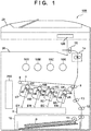
- FIG. 1 is a schematic cross-sectional view of an image forming apparatus 100 including a reader 20 and a color printer 30. Note that the reader 20 may be omitted.
- the color printer 30 forms a toner image using yellow, magenta, cyan, and black toner.
- the letters Y, M, C, and K provided at the end of reference numerals respectively mean yellow, magenta, cyan, and black. When content shared by configurations for forming a toner image having each color is described, the above-described letters (Y, M, C, and K) will be omitted.
- a photosensitive drum 1 is an aluminum cylinder provided with a photosensitive layer on its surface. The photosensitive drum 1 functions as a photoreceptor.
- a laser scanner 3 has a light source, and exposes the photosensitive drum 1 to light emitted from the light source. Accordingly, an electrostatic latent image is formed on the photosensitive drum 1.
- a process cartridge 5 has a charging roller 2 and a development sleeve 4. The charging roller 2 evenly charges the surface of the photosensitive drum 1. Note that the image forming apparatus 100 may have a charging wire instead of the charging roller 2.
- the development sleeve 4 develops an electrostatic latent image using toner stored in the process cartridges 5. Accordingly, a toner image is formed on the photosensitive drum 1.
- a primary transfer roller 6 transfers the toner image formed on the photosensitive drum 1 to an intermediate transfer member 7.
- the intermediate transfer member 7 is an endless belt, is driven by a drive roller 8, and rotates.
- the intermediate transfer member 7 is not limited to a belt, and may be a tubular metal roller (referred to as an intermediate transfer drum). Toner images having different colors are superimposed and transferred onto the intermediate transfer member 7 to form a full-color toner image.
- the intermediate transfer member 7 conveys the toner image to a secondary transfer portion.
- the secondary transfer portion is a nip portion located between the intermediate transfer member 7 and a secondary transfer roller 9.
- a cassette 10 houses sheets P.
- a pickup roller 11 picks up a sheet P and sends the sheet P to a conveyance path.
- Conveyance rollers 12 provided on the conveyance path convey the sheet P to registration rollers 13.
- the registration rollers 13 supply the sheet P to the secondary transfer portion such that a timing when the toner image reaches the secondary transfer portion and a timing when the sheet P reaches the secondary transfer portion coincide with each other.
- the secondary transfer portion is constituted by the intermediate transfer member 7 and the secondary transfer rollers 9.
- the secondary transfer rollers 9 convey the sheet P while holding the sheet P together with the intermediate transfer member 7, and thus transfer the toner image carried by the intermediate transfer member 7 to the sheet P.
- the sheet P to which the toner image is transferred is conveyed to a fixing device 14.
- the fixing device 14 includes a heater for heating the toner image on the sheet P, and a pair of rotary members that convey the sheet P while holding the sheet P on which the toner image is carried.
- the fixing device 14 applies heat and pressure to the toner image and the sheet P using the heater and the rotary members, and fixes the toner image onto the sheet P.
- Discharge rollers 15 discharge the sheet P to which the toner image is fixed by the fixing device 14 onto a discharge tray.
- a toner container in which toner is housed is mounted on a mounting portion 16. Toner stored in the process cartridge 5 is consumed as a result of forming a toner image.
- the image forming apparatus 100 replenishes the process cartridge 5 with toner from the toner container mounted on the mounting portion 16.
- the image forming apparatus 100 replenishes the process cartridge 5 with toner from the toner container as a result of rotation of the toner container. Note that the image forming apparatus 100 may insert a paddle into the toner container and rotate this paddle, and thus replenish the process cartridge 5 with toner from the toner container.
- the toner container functions as a toner replenishing unit.
- An operation panel 126 includes a display and a plurality of keys for inputting information. Note that the operation panel 126 may be a touch panel display having no keys. The operation panel 126 is connected to a printed circuit board 200.
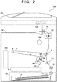
- FIG. 2 is a schematic cross-sectional view of an image forming apparatus 100' including a reader 20 and a monochrome printer 30'. Constituent elements of the image forming apparatus 100' that are the same as those of the image forming apparatus 100 shown in FIG. 1 are given the same reference numerals. Also, the same constituent elements will not be described.
- the image forming apparatus 100' shown in FIG. 2 is the image forming apparatus 100 shown in FIG. 1 with the parts for color printing removed.
- the image forming apparatus 100' shown in FIG. 2 is a subset of the image forming apparatus 100 shown in FIG. 1 .
- the image forming apparatus 100' shown in FIG. 2 and the image forming apparatus 100 shown in FIG. 1 can share many parts including the printed circuit board 200. Thus, it is possible to reduce the manufacturing cost of the image forming apparatuses 100 and 100'.
- Parts of the image forming apparatus 100' are the same as parts of the image forming apparatus 100, and thus a description thereof will be omitted.
- FIG. 3 is a schematic diagram showing a relationship between the printed circuit board 200 and control targets.
- the printed circuit board 200 controls units of the image forming apparatuses 100 and 100'.
- the printed circuit board 200 can be mounted in both the image forming apparatus 100 that forms color images and the image forming apparatus 100' that forms monochromatic images.
- a CPU 201 is a control circuit that performs overall control of the image forming apparatus 100 (or the image forming apparatus 100'). Control programs for controlling various types of processing are stored in a ROM 202.
- the CPU 201 executes various control sequences according to control programs stored in the ROM 202.
- a RAM 222 stores temporary data regarding control sequences.
- the RAM 222 functions as a system work memory used by the CPU 201 for arithmetic processing.
- the CPU 201 displays information on a display of the operation panel 126, and receives information and instructions input from the operation panel 126 using a plurality of keys.
- An ADC 203 is an analog-digital converter that converts an electric current output from a temperature sensor 204 to a digital signal.
- the temperature sensor 204 outputs an electric current corresponding to the temperature of the fixing device 14.
- a high-voltage control circuit 205 controls a high-voltage power source 206.
- the high-voltage power source 206 generates a charging voltage to be applied to the charging roller 2, a development voltage to be applied to the development sleeve 4, a primary transfer voltage to be applied to the primary transfer roller 6, and a secondary transfer voltage to be applied to the secondary transfer rollers 9.
- a motor control circuit 207 controls motor units 211a and 211b.
- the motor unit 211a includes motors M1K and M1YMC that are shown in FIG.
- the motor unit 211b includes motors M2Y, M2M, M2C, and M2K, which are shown in FIG. 4 , for rotating the toner containers mounted on the mounting portions 16.
- a load control circuit 208 controls a DC load 213.
- the DC load 213 includes a solenoid and a clutch that are driven to convey the sheet P.
- a sensor IF 209 is an interface circuit that transfers a detection signal output by a sensor group 214 to the CPU 201.
- the sensor group 214 includes an inductance sensor and a photo-interrupter.
- An AC drive circuit 210 controls the alternating electric current flowing to the heater of the fixing device 14.
- the CPU 201 controls an alternating electric current flowing to the heater of the fixing device 14 such that the temperature measured by the temperature sensor 204 reaches a target temperature.
- FIG. 4 is a schematic diagram of main portions of the printed circuit board 200 mounted in the color printer 30.
- a plurality of connectors including connectors 301a, 301b, 301c, and 301d are arranged on the printed circuit board 200.
- the motor unit 211a includes the motor M1YMC that drives the photosensitive drums 1Y, 1M, and 1C and the development sleeves 4Y, 4M, and 4C, and the motor M1K that drives the photosensitive drum 1K and the development sleeve 4K.
- a control line 401a is a signal cable for communicably connecting the motor control circuit 207 and the motor M1K.
- a control line 401b is a signal cable for communicably connecting the motor control circuit 207 and the motor M1YMC.
- a connector of the control line 401a is connected to the connector 301a.
- the motor control circuit 207 outputs a control signal to the motor M1K through the control line 401a.
- a connector of the control line 401b is connected to the connector 301b.
- the motor control circuit 207 outputs a control signal to the motor M1YMC through the control line 401b.
- the control line 401a is an example of a control line for transferring a control signal to a first driving source that drives a first image forming unit that forms a toner image using toner having a first color (e.g., black).
- the motor M1K is an example of the first driving source.
- the control line 401b is an example of a control line for transferring a control signal to a second driving source that drives a second image forming unit that forms a toner image using toner having a second color that is different from the first color.
- the motor M1YMC is an example of the second driving source.
- the motor unit 211b includes motors M2Y, M2M, M2C, and M2K that drive the toner containers mounted on the mounting portions 16Y, 16M, 16C, and 16K.
- a control line 401c is a signal cable for communicably connecting the motor control circuit 207 and the motor M2K.
- a control line 401d is a signal cable for communicably connecting the motor control circuit 207 and the motors M2Y, M2M, and M2C.
- a connector of the control line 401c is connected to the connector 301c.
- the motor control circuit 207 outputs a control signal to the motor M2K through the control line 401c.
- a connector of the control line 401d is connected to the connector 301d.
- the motor control circuit 207 outputs control signals to the motors M2Y, M2M, and M2C through the control line 401d.
- the control line 401c is an example of a control line for transferring a control signal to a third driving source that supplements, with toner from the first toner container, the first image forming unit that forms a toner image using toner having the first color.
- the motor M2K is an example of the third driving source.
- the toner container mounted on the mounting portion 16K is an example of the first toner container.
- the control line 401d is an example of a control line for transferring a control signal to a fourth driving source that supplements, with toner from a second toner container, the second image forming unit that forms a toner image using toner having the second color that is different from the first color.
- the motors M2Y, M2M, and M2C are examples of the fourth driving source.
- the toner container mounted on the mounting portion 16Y is an example of the second toner container.
- the second toner container may be a toner container mounted on the mounting portion 16M, or a toner container mounted on the mounting portion 16C.
- the first color may be black.
- the second color may be a chromatic color such as yellow, magenta, or cyan.
- a mark 310b is provided around the connector 301b of the printed circuit board 200 shown in FIG. 4
- a mark 310d is provided around the connector 301d of the printed circuit board 200. That is, marks are provided around the connectors 301b and 301d dedicated to the color printer 30'. Note that the marks 310b and 310d are printed on the printed circuit board 200 through silk screen printing.
- no marks are provided around the connectors 301a and 301c of the printed circuit board 200 shown in FIG. 4 . That is, no marks are provided around the shared connectors 301a and 301c.
- the image forming apparatus 100' that forms monochromatic images is designed based on the image forming apparatus 100 that forms full color images.
- the image forming apparatus 100' has functions that are equivalent to those of the image forming apparatus 100, except that the image forming apparatus 100' cannot form yellow, magenta, and cyan toner images.
- the image forming apparatus 100' is different from the image forming apparatus 100 in that the image forming apparatus 100' does not have the process cartridges 5Y, 5M, and 5C and the motors M1YMC, M2Y, M2C, and M2M. Note that in the image forming apparatus 100', the mounting portions 16Y, 16M, and 16C are covered by a cover such that the toner container housing black toner is not erroneously mounted on the mounting portions 16Y, 16M, or 16C.
- FIG. 5 is a schematic diagram of main portions of the printed circuit board 200 mounted in the monochrome printer 30'.
- the printed circuit board 200 shown in FIG. 5 is the same as the printed circuit board 200 shown in FIG. 4 .
- the connector 301a of the printed circuit board 200 is connected to the connector of the control line 401a
- the connector 301c of the printed circuit board 200 is connected to the connector of the control line 401c.
- the monochrome printer 30' does not need control lines 401b or 401d.
- an operator connects the control line 401a to the connector 301a, and connects the control line 401c to the connector 301c in a process for manufacturing the image forming apparatus 100', a process for assembling the image forming apparatus 100', and maintenance of the image forming apparatus 100'.
- the connectors 301a and 301c to which motors for the monochrome printer 30' are connected are different from the connectors 301b and 301d to which the motors for the color printer 30 are connected. If the printed circuit board 200 is mounted in the monochrome printer 30', the control lines 401a and 401c for the monochrome printer 30' are connected to the connectors 301a and 301c, and the control lines 401b and 401d for the color printer 30 are not connected to any connectors. That is, the control lines 401b and 401d are parts dedicated to the color printer 30.
- control lines 401a and 401c for black are commonized parts that are connected to the connectors 301a and 301c of both the monochrome printer 30' and the color printer 30. That is, the printed circuit board 200 and the control lines 401a and 401c are commonized parts.
- the connectors of the control lines are not connected to the connectors 301b and 301d.
- the marks 310b and 310d are provided around the connectors 301b and 301d.
- the marks 310b and 310d indicate that the connectors 301b and 301d are not connected to the connectors of the control lines when the printed circuit board 200 is mounted in the monochrome printer 30'.
- An operator can easily determine whether or not the connectors of the control lines are to be connected to the connectors 301b and 301 d of the printed circuit board 200, based on whether or not the marks 310b and 310d are provided.
- the marks 310b and 310d printed on the printed circuit board 200 are effective for inhibiting an operator from erroneously connecting the control lines 401a and 401c to the connectors 301b and 301d in an assembly operation and a maintenance operation. Also, no marks are provided around the connectors 301a and 301c of the printed circuit board 200. Thus, if the printed circuit board 200 is mounted in the monochrome printer 30', an operator can easily recognize that the connectors of the control lines 401a and 401c are to be connected to the connectors 301a and 301c.
- the connector 301a of the printed circuit board 200 is an example of a commonized connector (a first connector) that is used in both the monochrome printer 30' and the color printer 30.
- the connector 301b of the printed circuit board 200 is an example of a dedicated connector (a second connector) that is used in the monochrome printer 30' and is not used in the color printer 30.
- the connector 301c of the printed circuit board 200 is an example of another commonized connector (a third connector) that is used in both the monochrome printer 30' and the color printer 30.
- the connector 301d of the printed circuit board 200 is an example of another dedicated connector (a fourth connector) that is used in the monochrome printer 30' and is not used in the color printer 30.
- the marks 310b and 310d of the printed circuit board 200 are marks for distinguishing between a commonized connector and a dedicated connector, and are examples of a mark that is formed around a dedicated connector.
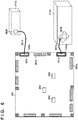
- FIG. 6 is a schematic diagram of main portions of a variation of the printed circuit board 200 mounted in the monochrome printer 30'.
- the printed circuit board 200 shown in FIG. 6 is the same as the printed circuit board 200 shown in FIG. 4 or 5 .
- a connector 301a of the printed circuit board 200 is connected to a connector of a control line 401a
- a connector 301c of the printed circuit board 200 is connected to a connector of a control line 401c.
- a mark 310a is provided around the connector 301a of the printed circuit board 200 shown in FIG. 6
- a mark 310c is provided around the connector 301c of the printed circuit board 200.
- no marks are provided around the connectors 301b and 301d of the printed circuit board 200 shown in FIG. 6 .
- the printed circuit board 200 is provided with marks around commonized connectors that are used in both the monochrome printer 30' and the color printer 30, and is not provided with a mark around a dedicated connector that is used only in the color printer 30.
- first marks are provided around the connectors 301b and 301d
- second marks that are different from the first marks are provided around the connectors 301a and 301c.
- the first marks that are provided for the connectors 301b and 301d and the second marks that are provided for the connectors 301a and 301c need to be visually distinguishable marks.
- FIGS. 7A, 7B, and 7C show other examples of the mark 310.
- a mark 310 shown in FIG. 7A is a broken line provided around the connector 301 through silk screen printing.
- a mark 310 shown in FIG. 7B is letters provided around the connector 301 through silk screen printing. These letters may indicate that a control line is not connected to this connector in the monochrome printer 30'.
- a mark 310 shown in FIG. 7C is a frame line provided to enclose a number (connector number) for specifying a connector. Connector numbers are pieces of unique identification information that are provided to a plurality of connectors provided on a printed circuit board. A connector number is provided in the vicinity of the connector 301 through silk screen printing. The mark 310 is also provided through silk screen printing.
- marks having different colors may be provided on the printed circuit board 200 such that an operator can determine whether or not a control line is to be connected to each connector.
- a mark in a first color e.g., white
- a mark in a second color e.g., yellow
- a mark may be provided around a commonized connector, and is not necessarily provided around a dedicated connector.
- a mark may be provided around a dedicated connector, and is not necessarily provided around a commonized connector.
- a mark may be provided to enclose the connector 301 on the printed circuit board 200.
- the mark 310 may be a letter, a figure, or a symbol provided in the vicinity of the connector 301.
- the mark 310 may be a mark provided on information (e.g., connector numbers) for identifying a plurality of connectors 301. Such information may also be referred to as connector identification information.
- FIGS. 8 , 9A, and 9B are schematic diagrams of main portions of a printed circuit board 200 according to a second embodiment.
- FIG. 8 With the printed circuit board 200 shown in FIG. 8 , connectors and marks provided around the connectors are different from the connectors and marks of the first embodiment. Note that other constituent elements of the printed circuit board 200 of the second embodiment are the same as the constituent elements of the printed circuit board 200 of the first embodiment. Thus, shared constituent elements will not be described herein.
- the printed circuit board 200 shown in FIG. 8 includes connectors 800 to 809.
- the connector 800 is connected to a connector of a control line extending from a motor M1K.
- the connector 801 is connected to a connector of a control line extending from a motor M1YMC.
- the connector 802 is connected to a connector of a control line extending from a motor M2K.
- the connector 803 is connected to a connector of control lines extending from motors M2Y, M2M, and M2C.
- the connector 804 is connected to a connector of a control line extending from a motor M3 for rotating secondary transfer rollers 9.
- Other connectors 805 to 809 are connected to control lines extending from an operation panel 126, a temperature sensor 204, a DC load 213, and a sensor group 214.
- the printed circuit board 200 is provided with marks indicating regions occupied by the connectors 800 to 809 around the connectors 800 to 809. These occupied regions indicate positions at which the connectors 800 to 809 are arranged. Also, the printed circuit board 200 is provided with marks 810 to 819 in the vicinities of the connectors 800 to 809. The marks 810 to 819 include identification numbers (J0 to J9) for identifying which of the connectors 800 to 809 is to be connected to.
- the marks 810, 812, and 814 are obtained by enclosing identification numbers (J0, J2, and J4) in rectangles.
- the marks 810, 812, and 814 indicate that the connectors 800, 802, and 804 are commonized connectors that are used in both a monochrome printer 30' and a color printer 30.
- marks 811 and 813 are obtained by enclosing identification numbers (J1 and J3) in double-rectangles.
- the marks 811 and 813 indicate that the connectors 801 and 803 are dedicated connectors that are used only in the color printer 30.
- the connectors 805 to 809 corresponding to the marks 815 to 819 are also commonized connectors.
- the marks 815 to 819 are different from the marks 810, 812, and 814. That is, unlike the marks 810, 812, and 814, with regard to the marks 815 to 819, identification numbers are not enclosed in rectangles. These marks are designed taking the convenience for an operator to maintain and assemble the color printer 30 (or the monochrome printer 30') into consideration.
- reasons why the marks 815 to 819 are different from the marks 800 to 804 will be described with reference to FIGS. 9A and 9B .
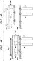
- FIG. 9A is a schematic cross-sectional view of a motor assembly 900 in a state in which the motor assembly 900 is mounted on a rear side plate 1000 of the color printer 30 (the monochrome printer 30').
- FIG. 9B is a schematic cross-sectional view of the motor assembly 900 in a state in which the motor assembly 900 is detached from the rear side plate 1000.
- the motor assembly 900 is a sub-unit in which motor units 211a and 211b, a motor M3, and a printed circuit board 200 are fixed to a housing.
- the motor M3 is a driving source for rotating and driving a secondary transfer roller 9.
- the motor assembly 900 can be attached to or detached from the rear side plate 1000 of the color printer 30 (the monochrome printer 30').
- a gear of the motor M1 and a gear of a photosensitive drum 1 are connected to each other to be capable of transmitting driving force
- a gear of the motor M2 and a gear for driving a replenishment mechanism are connected to each other to be capable of transmitting driving force.
- a gear of the motor M3 and a gear for driving the secondary transfer rollers 9 are connected to each other to be capable of transmitting driving force.
- the motor units 211a and 211b and the motor M3 that are fixed as the motor assembly 900 to the same housing as the printed circuit board 200 are detached all at once from the rear side plate 1000 together with the printed circuit board 200.
- the operator does not need to detach the connectors of all of the control lines from the connectors 800 to 809 of the printed circuit board 200. That is, the marks 810 to 814 of the printed circuit board 200 allow an operator to recognize that when the motor assembly 900 is detached from the rear side plate 1000, the connectors of the control lines need not be detached from the connectors 800 to 804.
- the time and effort required when an operator detaches the motor assembly 900 decrease, and the operation time can be shortened.
- the printed circuit board 200 of the present embodiment not only can an operator easily distinguish between a commonized connector and a dedicated connector, but also the efficiency of a maintenance operation can be improved.
- the image forming apparatus 100' is an example of a monochromatic image forming apparatus.
- the monochrome printer 30' is an example of an image forming unit that forms a black image.
- the motors M1K and M2K are examples of motors driving an image forming unit to form a black image.
- the motor control circuit 207 is an example of a control circuit that controls a motor.
- the connectors 301a and 301c are examples of a first connector to which a motor is connected via a control line.
- the connectors 301b and 301d are examples of a second connector to which a control target is not connected.
- the printed circuit board 200 is an example of a substrate on which the control circuit, the first connector, and the second connector are arranged.
- the marks 310b and 310d are examples of a predetermined mark formed on a substrate through silk screen printing.
- the distance between a predetermined mark and a second connector of the substrate is shorter than the distance between the predetermined mark and a first connector of the substrate.
- the motor M1YMC and the motors M2Y, M2M, and M2C which are control targets for the multi-color image forming apparatus, are connected to second connectors.
- the image forming unit may have a photoreceptor (the photosensitive drum 1K) on which an electrostatic latent image is formed, and a development sleeve (the development sleeve 4K) that develops the electrostatic latent image formed on the photoreceptor, using black toner.
- the motor (the motor M1K) rotates the photoreceptor.
- the image forming unit may have a photoreceptor (the photosensitive drum 1K) on which an electrostatic latent image is formed, and a development sleeve (the development sleeve 4K) that develops the electrostatic latent image formed on the photoreceptor, using black toner.
- the motor (the motor M1K) rotates the sleeve.
- the image forming unit may have a photoreceptor on which an electrostatic latent image is to be formed, a development sleeve that develops the electrostatic latent image formed on the photoreceptor, using black toner, and a mounting portion (the mounting portion 16K) on which a housing container is mounted.
- the black toner is housed in the housing container.
- a motor (the motor M2K) may be driven to replenish the image forming unit with the black toner in the housing container mounted on the mounting portion.
- a predetermined mark may be formed to enclose a region in which a second connector is disposed.
- First identification information for a first connector may be formed on a substrate through silk screen printing.
- Second identification information for a second connector may be formed on a substrate through silk screen printing.
- a predetermined mark may be added to second identification information.
- the mark 310 may be a mark provided on information (e.g., connector number) for identifying a plurality of connectors 301. Such information may also be referred to as connector identification information.
- a predetermined mark may be formed to enclose second identification information.
- a predetermined mark may include at least one of a letter, a figure, and a symbol.
- the printed circuit board 200 is an example of a substrate on which a control circuit, a first connector, and a second connector are arranged.
- a predetermined mark (e.g.: the marks 310a and 310c) formed through silk screen printing may be formed on a substrate. The distance between a predetermined mark and a first connector of the substrate is shorter than the distance between the predetermined mark and a second connector of the substrate.
- a control target e.g.: the motor M1YMC, and the motors M2Y, M2M, and M2C
- a control target e.g.: the motor M1YMC, and the motors M2Y, M2M, and M2C
- a predetermined mark may be formed to enclose a region in which a first connector is disposed.
- a predetermined mark may be added to first identification information.
- a predetermined mark may be formed to enclose second identification information.
- a predetermined mark may include at least one of a letter, a figure, and a symbol.
- the image forming apparatus 100 (a color machine) is an example of an image forming apparatus.
- the color printer 30 is an example of an image forming unit that forms images using toner having different colors.
- the motors M1K and M2K are examples of a first motor configured to drive an image forming unit to form a black image using black toner.
- the motor M1YMC, and the motors M2Y, M2M, and M2C are examples of a second motor configured to drive an image forming unit to form a color image using color toner.
- the connectors 301a and 301c are examples of a first connector to which a first motor is connected via a first control line.
- the connectors 301b and 301d are examples of a second connector to which a second motor is connected via a second control line.
- the printed circuit board 200 is an example of a substrate on which the control circuit, the first connector, and the second connector are arranged.
- the marks 310b and 310d are examples of a predetermined mark formed on a substrate through silk screen printing. The distance between a predetermined mark and a second connector of the substrate is shorter than the distance between the predetermined mark and a first connector of the substrate. If the substrate is disposed in the image forming apparatus 100', which is a monochromatic image forming apparatus that forms only black images, there is no motor that is to be connected to the second connector.
- First identification information for a first connector is formed on a substrate through silk screen printing.
- Second identification information for a second connector is formed on a substrate through silk screen printing. As shown in FIG. 7B , a predetermined mark may be added to the second identification information.
- the distance between a predetermined mark and a first connector of the substrate is shorter than the distance between the predetermined mark and a second connector of the substrate.
- the substrate is disposed in the image forming apparatus 100', which is a monochromatic image forming apparatus that forms only black images, there is no motor that is to be connected to the second connector.
- First identification information for a first connector may be formed on the substrate through silk screen printing.
- Second identification information for a second connector may be formed on the substrate through silk screen printing.
- a predetermined mark may be added to first identification information.
- Embodiment(s) of the present invention can also be realized by a computer of a system or apparatus that reads out and executes computer executable instructions (e.g., one or more programs) recorded on a storage medium (which may also be referred to more fully as a 'non-transitory computer-readable storage medium') to perform the functions of one or more of the above-described embodiment(s) and/or that includes one or more circuits (e.g., application specific integrated circuit (ASIC)) for performing the functions of one or more of the above-described embodiment(s), and by a method performed by the computer of the system or apparatus by, for example, reading out and executing the computer executable instructions from the storage medium to perform the functions of one or more of the above-described embodiment(s) and/or controlling the one or more circuits to perform the functions of one or more of the above-described embodiment(s).
- computer executable instructions e.g., one or more programs
- a storage medium which may also be referred to more fully as
- the computer may comprise one or more processors (e.g., central processing unit (CPU), micro processing unit (MPU)) and may include a network of separate computers or separate processors to read out and execute the computer executable instructions.
- the computer executable instructions may be provided to the computer, for example, from a network or the storage medium.
- the storage medium may include, for example, one or more of a hard disk, a random-access memory (RAM), a read only memory (ROM), a storage of distributed computing systems, an optical disk (such as a compact disc (CD), digital versatile disc (DVD), or Blu-ray Disc (BD)TM), a flash memory device, a memory card, and the like.
- An image forming unit (30') forms a black image.
- a motor (M1K; M2K) drives the image forming unit.
- a control circuit (207) controls the motor.
- a first connector (301a; 301c) to which the motor is connected via a control line.
- a second connector (301b; 301d) to which a control target is not connected.
- a substrate (200) on which the control circuit, the first connector, and the second connector are arranged.
- a predetermined mark (310b; 310d) is formed on the substrate through silk screen printing. A distance between the predetermined mark and the second connector is shorter than a distance between the predetermined mark and the first connector.
Landscapes
- Physics & Mathematics (AREA)
- General Physics & Mathematics (AREA)
- Engineering & Computer Science (AREA)
- Microelectronics & Electronic Packaging (AREA)
- Electrophotography Configuration And Component (AREA)
- Facsimiles In General (AREA)
- Color Electrophotography (AREA)
Abstract
Description
- The present invention relates to an image forming apparatus provided with a commonized printed circuit board.
- Image forming apparatuses include multiple types of printers such as monochrome printers and color printers. In recent years, attempts have been made to commonize parts of different types of printers. Japanese Patent Laid-Open No.
2007-301822 - Incidentally, if a commonized printed circuit board that can be mounted in different types of printers is manufactured, the manufacturing cost of printed circuit boards is reduced because the amount of produced printed circuit boards increases. Thus, if a commonized printed circuit board is manufactured, the cost of a printer can be reduced.
- However, if a commonized printed circuit board is mounted in a monochrome printer, the number of connectors of cables for the monochrome printer is different from the number of connectors of the printed circuit board, and thus a new issue will arise in maintenance and an assembly process. For example, there is a possibility that an operator will erroneously connect a connector of a cable of the monochrome printer to a connector for a color printer on the commonized printed circuit board. If the connector is erroneously connected, the printer cannot operate normally. Also, if the connector is erroneously connected, there is a possibility that a pin of the connector will be bent. Even if a connector with a bent pin is connected to a correct connector of the printed circuit board, this connector is likely to cause connection failure. Thus, the printer to which a connector with a bent pin is connected cannot operate normally.
- The present invention is realized, for example, on a monochromatic image forming apparatus as specified in claims 1 to 10.
- Furthermore, the present invention is realized, for example, on an image forming apparatus as specified
claims 11 to 14. - Further features of the present invention will become apparent from the following description of exemplary embodiments with reference to the attached drawings.
-
-
FIG. 1 is a schematic cross-sectional view of an image forming apparatus including a reader and a color printer. -
FIG. 2 is a schematic cross-sectional view of an image forming apparatus including a reader and a monochrome printer. -
FIG. 3 is a schematic diagram showing a relationship between a printed circuit board and control targets. -
FIG. 4 is a schematic diagram of main portions of a printed circuit board of a first embodiment. -
FIG. 5 is a schematic diagram of the main portions of the printed circuit board of the first embodiment. -
FIG. 6 is a schematic diagram of main portions of another printed circuit board mounted in a monochrome printer. -
FIGS. 7A to 7C are other exemplary diagrams of marks printed on a printed circuit board. -
FIG. 8 is a schematic diagram of main portions of a printed circuit board of a second embodiment. -
FIGS. 9A and 9B are schematic cross-sectional views of motor assemblies that can be attached to and detached from a printer. - According to an embodiment, a printed circuit board that can be built in both a color printer that forms a color image and a monochrome printer that forms a monochromatic image is provided. The printed circuit board includes a first connector, a second connector, and a mark. The first connector is used in both a color printer and a single-color printer. The second connector is used in a color printer, and is not used in a single-color printer. The mark is a mark for distinguishing between the first connector and the second connector, and is provided on at least one of the first connector and the second connector. Accordingly, if a commonized printed circuit board is used in both a monochrome printer and a color printer, it is possible to avoid an error in attaching a cable.
-
FIG. 1 is a schematic cross-sectional view of animage forming apparatus 100 including areader 20 and acolor printer 30. Note that thereader 20 may be omitted. Thecolor printer 30 forms a toner image using yellow, magenta, cyan, and black toner. The letters Y, M, C, and K provided at the end of reference numerals respectively mean yellow, magenta, cyan, and black. When content shared by configurations for forming a toner image having each color is described, the above-described letters (Y, M, C, and K) will be omitted. A photosensitive drum 1 is an aluminum cylinder provided with a photosensitive layer on its surface. The photosensitive drum 1 functions as a photoreceptor. Alaser scanner 3 has a light source, and exposes the photosensitive drum 1 to light emitted from the light source. Accordingly, an electrostatic latent image is formed on the photosensitive drum 1. A process cartridge 5 has a charging roller 2 and a development sleeve 4. The charging roller 2 evenly charges the surface of the photosensitive drum 1. Note that theimage forming apparatus 100 may have a charging wire instead of the charging roller 2. The development sleeve 4 develops an electrostatic latent image using toner stored in the process cartridges 5. Accordingly, a toner image is formed on the photosensitive drum 1. - A primary transfer roller 6 transfers the toner image formed on the photosensitive drum 1 to an
intermediate transfer member 7. Note that theimage forming apparatus 100 may have a primary transfer blade instead of the primary transfer roller 6. Theintermediate transfer member 7 is an endless belt, is driven by adrive roller 8, and rotates. Note that theintermediate transfer member 7 is not limited to a belt, and may be a tubular metal roller (referred to as an intermediate transfer drum). Toner images having different colors are superimposed and transferred onto theintermediate transfer member 7 to form a full-color toner image. Theintermediate transfer member 7 conveys the toner image to a secondary transfer portion. The secondary transfer portion is a nip portion located between theintermediate transfer member 7 and asecondary transfer roller 9. - A
cassette 10 houses sheets P. Apickup roller 11 picks up a sheet P and sends the sheet P to a conveyance path.Conveyance rollers 12 provided on the conveyance path convey the sheet P toregistration rollers 13. Theregistration rollers 13 supply the sheet P to the secondary transfer portion such that a timing when the toner image reaches the secondary transfer portion and a timing when the sheet P reaches the secondary transfer portion coincide with each other. - The secondary transfer portion is constituted by the
intermediate transfer member 7 and thesecondary transfer rollers 9. Thesecondary transfer rollers 9 convey the sheet P while holding the sheet P together with theintermediate transfer member 7, and thus transfer the toner image carried by theintermediate transfer member 7 to the sheet P. The sheet P to which the toner image is transferred is conveyed to afixing device 14. The fixingdevice 14 includes a heater for heating the toner image on the sheet P, and a pair of rotary members that convey the sheet P while holding the sheet P on which the toner image is carried. The fixingdevice 14 applies heat and pressure to the toner image and the sheet P using the heater and the rotary members, and fixes the toner image onto the sheetP. Discharge rollers 15 discharge the sheet P to which the toner image is fixed by the fixingdevice 14 onto a discharge tray. - A toner container in which toner is housed is mounted on a mounting portion 16. Toner stored in the process cartridge 5 is consumed as a result of forming a toner image. The
image forming apparatus 100 replenishes the process cartridge 5 with toner from the toner container mounted on the mounting portion 16. Theimage forming apparatus 100 replenishes the process cartridge 5 with toner from the toner container as a result of rotation of the toner container. Note that theimage forming apparatus 100 may insert a paddle into the toner container and rotate this paddle, and thus replenish the process cartridge 5 with toner from the toner container. The toner container functions as a toner replenishing unit. - An
operation panel 126 includes a display and a plurality of keys for inputting information. Note that theoperation panel 126 may be a touch panel display having no keys. Theoperation panel 126 is connected to a printedcircuit board 200. -
FIG. 2 is a schematic cross-sectional view of an image forming apparatus 100' including areader 20 and a monochrome printer 30'. Constituent elements of the image forming apparatus 100' that are the same as those of theimage forming apparatus 100 shown inFIG. 1 are given the same reference numerals. Also, the same constituent elements will not be described. The image forming apparatus 100' shown inFIG. 2 is theimage forming apparatus 100 shown inFIG. 1 with the parts for color printing removed. The image forming apparatus 100' shown inFIG. 2 is a subset of theimage forming apparatus 100 shown inFIG. 1 . Thus, the image forming apparatus 100' shown inFIG. 2 and theimage forming apparatus 100 shown inFIG. 1 can share many parts including the printedcircuit board 200. Thus, it is possible to reduce the manufacturing cost of theimage forming apparatuses 100 and 100'. Parts of the image forming apparatus 100' are the same as parts of theimage forming apparatus 100, and thus a description thereof will be omitted. -
FIG. 3 is a schematic diagram showing a relationship between the printedcircuit board 200 and control targets. The printedcircuit board 200 controls units of theimage forming apparatuses 100 and 100'. The printedcircuit board 200 can be mounted in both theimage forming apparatus 100 that forms color images and the image forming apparatus 100' that forms monochromatic images. ACPU 201 is a control circuit that performs overall control of the image forming apparatus 100 (or the image forming apparatus 100'). Control programs for controlling various types of processing are stored in aROM 202. TheCPU 201 executes various control sequences according to control programs stored in theROM 202. ARAM 222 stores temporary data regarding control sequences. TheRAM 222 functions as a system work memory used by theCPU 201 for arithmetic processing. Also, theCPU 201 displays information on a display of theoperation panel 126, and receives information and instructions input from theoperation panel 126 using a plurality of keys. - An
ADC 203 is an analog-digital converter that converts an electric current output from atemperature sensor 204 to a digital signal. Thetemperature sensor 204 outputs an electric current corresponding to the temperature of the fixingdevice 14. A high-voltage control circuit 205 controls a high-voltage power source 206. The high-voltage power source 206 generates a charging voltage to be applied to the charging roller 2, a development voltage to be applied to the development sleeve 4, a primary transfer voltage to be applied to the primary transfer roller 6, and a secondary transfer voltage to be applied to thesecondary transfer rollers 9. Amotor control circuit 207 controlsmotor units motor unit 211a includes motors M1K and M1YMC that are shown inFIG. 4 , the motors M1K and M1YMC driving the photosensitive drum 1 and the development sleeve 4. Themotor unit 211b includes motors M2Y, M2M, M2C, and M2K, which are shown inFIG. 4 , for rotating the toner containers mounted on the mounting portions 16. Aload control circuit 208 controls aDC load 213. TheDC load 213 includes a solenoid and a clutch that are driven to convey the sheet P. A sensor IF 209 is an interface circuit that transfers a detection signal output by asensor group 214 to theCPU 201. Thesensor group 214 includes an inductance sensor and a photo-interrupter. AnAC drive circuit 210 controls the alternating electric current flowing to the heater of the fixingdevice 14. For example, theCPU 201 controls an alternating electric current flowing to the heater of the fixingdevice 14 such that the temperature measured by thetemperature sensor 204 reaches a target temperature. -
FIG. 4 is a schematic diagram of main portions of the printedcircuit board 200 mounted in thecolor printer 30. A plurality ofconnectors including connectors circuit board 200. - The
motor unit 211a includes the motor M1YMC that drives thephotosensitive drums development sleeves photosensitive drum 1K and thedevelopment sleeve 4K. Acontrol line 401a is a signal cable for communicably connecting themotor control circuit 207 and the motor M1K. Acontrol line 401b is a signal cable for communicably connecting themotor control circuit 207 and the motor M1YMC. A connector of thecontrol line 401a is connected to theconnector 301a. Themotor control circuit 207 outputs a control signal to the motor M1K through thecontrol line 401a. A connector of thecontrol line 401b is connected to theconnector 301b. Themotor control circuit 207 outputs a control signal to the motor M1YMC through thecontrol line 401b. Thecontrol line 401a is an example of a control line for transferring a control signal to a first driving source that drives a first image forming unit that forms a toner image using toner having a first color (e.g., black). The motor M1K is an example of the first driving source. Thecontrol line 401b is an example of a control line for transferring a control signal to a second driving source that drives a second image forming unit that forms a toner image using toner having a second color that is different from the first color. The motor M1YMC is an example of the second driving source. - The
motor unit 211b includes motors M2Y, M2M, M2C, and M2K that drive the toner containers mounted on the mountingportions control line 401c is a signal cable for communicably connecting themotor control circuit 207 and the motor M2K. Acontrol line 401d is a signal cable for communicably connecting themotor control circuit 207 and the motors M2Y, M2M, and M2C. A connector of thecontrol line 401c is connected to theconnector 301c. Themotor control circuit 207 outputs a control signal to the motor M2K through thecontrol line 401c. A connector of thecontrol line 401d is connected to theconnector 301d. Themotor control circuit 207 outputs control signals to the motors M2Y, M2M, and M2C through thecontrol line 401d. Thecontrol line 401c is an example of a control line for transferring a control signal to a third driving source that supplements, with toner from the first toner container, the first image forming unit that forms a toner image using toner having the first color. The motor M2K is an example of the third driving source. The toner container mounted on the mountingportion 16K is an example of the first toner container. Thecontrol line 401d is an example of a control line for transferring a control signal to a fourth driving source that supplements, with toner from a second toner container, the second image forming unit that forms a toner image using toner having the second color that is different from the first color. The motors M2Y, M2M, and M2C are examples of the fourth driving source. The toner container mounted on the mountingportion 16Y is an example of the second toner container. Note that the second toner container may be a toner container mounted on the mountingportion 16M, or a toner container mounted on the mountingportion 16C. The first color may be black. The second color may be a chromatic color such as yellow, magenta, or cyan. - A
mark 310b is provided around theconnector 301b of the printedcircuit board 200 shown inFIG. 4 , and amark 310d is provided around theconnector 301d of the printedcircuit board 200. That is, marks are provided around theconnectors marks circuit board 200 through silk screen printing. On the other hand, no marks are provided around theconnectors circuit board 200 shown inFIG. 4 . That is, no marks are provided around the sharedconnectors - The image forming apparatus 100' that forms monochromatic images is designed based on the
image forming apparatus 100 that forms full color images. The image forming apparatus 100' has functions that are equivalent to those of theimage forming apparatus 100, except that the image forming apparatus 100' cannot form yellow, magenta, and cyan toner images. The image forming apparatus 100' is different from theimage forming apparatus 100 in that the image forming apparatus 100' does not have theprocess cartridges portions portions -
FIG. 5 is a schematic diagram of main portions of the printedcircuit board 200 mounted in the monochrome printer 30'. The printedcircuit board 200 shown inFIG. 5 is the same as the printedcircuit board 200 shown inFIG. 4 . As shown inFIG. 5 , if the printedcircuit board 200 is mounted in the monochrome printer 30', there are no connectors of control lines for connection to theconnectors circuit board 200. On the other hand, theconnector 301a of the printedcircuit board 200 is connected to the connector of thecontrol line 401a, and theconnector 301c of the printedcircuit board 200 is connected to the connector of thecontrol line 401c. Thus, as shown inFIG. 5 , the monochrome printer 30' does not needcontrol lines control line 401a to theconnector 301a, and connects thecontrol line 401c to theconnector 301c in a process for manufacturing the image forming apparatus 100', a process for assembling the image forming apparatus 100', and maintenance of the image forming apparatus 100'. - Incidentally, the
connectors connectors color printer 30 are connected. If the printedcircuit board 200 is mounted in the monochrome printer 30', thecontrol lines connectors control lines color printer 30 are not connected to any connectors. That is, thecontrol lines color printer 30. On the other hand, thecontrol lines connectors color printer 30. That is, the printedcircuit board 200 and thecontrol lines - As shown in
FIG. 5 , if the printedcircuit board 200 is mounted in the monochrome printer 30', the connectors of the control lines are not connected to theconnectors circuit board 200 shown inFIG. 5 , themarks connectors marks connectors circuit board 200 is mounted in the monochrome printer 30'. An operator can easily determine whether or not the connectors of the control lines are to be connected to theconnectors circuit board 200, based on whether or not themarks marks circuit board 200 are effective for inhibiting an operator from erroneously connecting thecontrol lines connectors connectors circuit board 200. Thus, if the printedcircuit board 200 is mounted in the monochrome printer 30', an operator can easily recognize that the connectors of thecontrol lines connectors - In this manner, the
connector 301a of the printedcircuit board 200 is an example of a commonized connector (a first connector) that is used in both the monochrome printer 30' and thecolor printer 30. Theconnector 301b of the printedcircuit board 200 is an example of a dedicated connector (a second connector) that is used in the monochrome printer 30' and is not used in thecolor printer 30. Theconnector 301c of the printedcircuit board 200 is an example of another commonized connector (a third connector) that is used in both the monochrome printer 30' and thecolor printer 30. Theconnector 301d of the printedcircuit board 200 is an example of another dedicated connector (a fourth connector) that is used in the monochrome printer 30' and is not used in thecolor printer 30. Themarks circuit board 200 are marks for distinguishing between a commonized connector and a dedicated connector, and are examples of a mark that is formed around a dedicated connector. - Next, a variation of the present invention will be described.
FIG. 6 is a schematic diagram of main portions of a variation of the printedcircuit board 200 mounted in the monochrome printer 30'. The printedcircuit board 200 shown inFIG. 6 is the same as the printedcircuit board 200 shown inFIG. 4 or5 . As shown inFIG. 6 , if the printedcircuit board 200 is mounted in the monochrome printer 30', there are no connectors of control lines for connection toconnectors circuit board 200. On the other hand, aconnector 301a of the printedcircuit board 200 is connected to a connector of acontrol line 401a, and aconnector 301c of the printedcircuit board 200 is connected to a connector of acontrol line 401c. - A
mark 310a is provided around theconnector 301a of the printedcircuit board 200 shown inFIG. 6 , and amark 310c is provided around theconnector 301c of the printedcircuit board 200. On the other hand, no marks are provided around theconnectors circuit board 200 shown inFIG. 6 . In this manner, a configuration is possible in which the printedcircuit board 200 is provided with marks around commonized connectors that are used in both the monochrome printer 30' and thecolor printer 30, and is not provided with a mark around a dedicated connector that is used only in thecolor printer 30. Also, as another variation of the printedcircuit board 200, a configuration is possible in which first marks are provided around theconnectors connectors connectors connectors - Also,
FIGS. 7A, 7B, and 7C show other examples of themark 310. Amark 310 shown inFIG. 7A is a broken line provided around theconnector 301 through silk screen printing. Amark 310 shown inFIG. 7B is letters provided around theconnector 301 through silk screen printing. These letters may indicate that a control line is not connected to this connector in the monochrome printer 30'. Amark 310 shown inFIG. 7C is a frame line provided to enclose a number (connector number) for specifying a connector. Connector numbers are pieces of unique identification information that are provided to a plurality of connectors provided on a printed circuit board. A connector number is provided in the vicinity of theconnector 301 through silk screen printing. Themark 310 is also provided through silk screen printing. Also, marks having different colors may be provided on the printedcircuit board 200 such that an operator can determine whether or not a control line is to be connected to each connector. For example, in the image forming apparatus 100', a mark in a first color (e.g., white) may be provided for a connector to which a cable is to be connected, and a mark in a second color (e.g., yellow) may be provided for a connector to which no cable is to be connected. - As shown in
FIG. 6 , a mark may be provided around a commonized connector, and is not necessarily provided around a dedicated connector. Alternatively, as shown inFIG. 4 , a mark may be provided around a dedicated connector, and is not necessarily provided around a commonized connector. A mark may be provided to enclose theconnector 301 on the printedcircuit board 200. As shown inFIG. 7B , themark 310 may be a letter, a figure, or a symbol provided in the vicinity of theconnector 301. Also, as shown inFIG. 7C , themark 310 may be a mark provided on information (e.g., connector numbers) for identifying a plurality ofconnectors 301. Such information may also be referred to as connector identification information. -
FIGS. 8 ,9A, and 9B are schematic diagrams of main portions of a printedcircuit board 200 according to a second embodiment. With the printedcircuit board 200 shown inFIG. 8 , connectors and marks provided around the connectors are different from the connectors and marks of the first embodiment. Note that other constituent elements of the printedcircuit board 200 of the second embodiment are the same as the constituent elements of the printedcircuit board 200 of the first embodiment. Thus, shared constituent elements will not be described herein. - The printed
circuit board 200 shown inFIG. 8 includesconnectors 800 to 809. Theconnector 800 is connected to a connector of a control line extending from a motor M1K. Theconnector 801 is connected to a connector of a control line extending from a motor M1YMC. The connector 802 is connected to a connector of a control line extending from a motor M2K. Theconnector 803 is connected to a connector of control lines extending from motors M2Y, M2M, and M2C. Theconnector 804 is connected to a connector of a control line extending from a motor M3 for rotatingsecondary transfer rollers 9.Other connectors 805 to 809 are connected to control lines extending from anoperation panel 126, atemperature sensor 204, aDC load 213, and asensor group 214. - The printed
circuit board 200 is provided with marks indicating regions occupied by theconnectors 800 to 809 around theconnectors 800 to 809. These occupied regions indicate positions at which theconnectors 800 to 809 are arranged. Also, the printedcircuit board 200 is provided withmarks 810 to 819 in the vicinities of theconnectors 800 to 809. Themarks 810 to 819 include identification numbers (J0 to J9) for identifying which of theconnectors 800 to 809 is to be connected to. - Also, the
marks marks connectors color printer 30. On the other hand, marks 811 and 813 are obtained by enclosing identification numbers (J1 and J3) in double-rectangles. Themarks connectors color printer 30. - Incidentally, the
connectors 805 to 809 corresponding to themarks 815 to 819 are also commonized connectors. However, themarks 815 to 819 are different from themarks marks marks 815 to 819, identification numbers are not enclosed in rectangles. These marks are designed taking the convenience for an operator to maintain and assemble the color printer 30 (or the monochrome printer 30') into consideration. Hereinafter, reasons why themarks 815 to 819 are different from themarks 800 to 804 will be described with reference toFIGS. 9A and 9B . -
FIG. 9A is a schematic cross-sectional view of amotor assembly 900 in a state in which themotor assembly 900 is mounted on arear side plate 1000 of the color printer 30 (the monochrome printer 30'). On the other hand,FIG. 9B is a schematic cross-sectional view of themotor assembly 900 in a state in which themotor assembly 900 is detached from therear side plate 1000. Themotor assembly 900 is a sub-unit in whichmotor units circuit board 200 are fixed to a housing. Herein, the motor M3 is a driving source for rotating and driving asecondary transfer roller 9. - In an image forming apparatus 100 (or an image forming apparatus 100'), the
motor assembly 900 can be attached to or detached from therear side plate 1000 of the color printer 30 (the monochrome printer 30'). When themotor assembly 900 is mounted on therear side plate 1000, a gear of the motor M1 and a gear of a photosensitive drum 1 are connected to each other to be capable of transmitting driving force, and a gear of the motor M2 and a gear for driving a replenishment mechanism are connected to each other to be capable of transmitting driving force. Similarly, when themotor assembly 900 is mounted on therear side plate 1000, a gear of the motor M3 and a gear for driving thesecondary transfer rollers 9 are connected to each other to be capable of transmitting driving force. Accordingly, as a result of an operator mounting themotor assembly 900 on therear side plate 1000, the efficiency of an assembly operation is improved. Also, as a result of an operator detaching themotor assembly 900 from therear side plate 1000, an operator can easily gain access to the photosensitive drum 1 and thesecondary transfer rollers 9 during maintenance. - Herein, the
motor units motor assembly 900 to the same housing as the printedcircuit board 200 are detached all at once from therear side plate 1000 together with the printedcircuit board 200. Thus, when an operator detaches themotor assembly 900 from therear side plate 1000, the operator does not need to detach the connectors of all of the control lines from theconnectors 800 to 809 of the printedcircuit board 200. That is, themarks 810 to 814 of the printedcircuit board 200 allow an operator to recognize that when themotor assembly 900 is detached from therear side plate 1000, the connectors of the control lines need not be detached from theconnectors 800 to 804. Accordingly, the time and effort required when an operator detaches themotor assembly 900 decrease, and the operation time can be shortened. Thus, according to the printedcircuit board 200 of the present embodiment, not only can an operator easily distinguish between a commonized connector and a dedicated connector, but also the efficiency of a maintenance operation can be improved. - In this manner, the image forming apparatus 100' is an example of a monochromatic image forming apparatus. The monochrome printer 30' is an example of an image forming unit that forms a black image. The motors M1K and M2K are examples of motors driving an image forming unit to form a black image. The
motor control circuit 207 is an example of a control circuit that controls a motor. Theconnectors connectors circuit board 200 is an example of a substrate on which the control circuit, the first connector, and the second connector are arranged. Themarks - The image forming unit may have a photoreceptor (the
photosensitive drum 1K) on which an electrostatic latent image is formed, and a development sleeve (thedevelopment sleeve 4K) that develops the electrostatic latent image formed on the photoreceptor, using black toner. The motor (the motor M1K) rotates the photoreceptor. - The image forming unit may have a photoreceptor (the
photosensitive drum 1K) on which an electrostatic latent image is formed, and a development sleeve (thedevelopment sleeve 4K) that develops the electrostatic latent image formed on the photoreceptor, using black toner. The motor (the motor M1K) rotates the sleeve. - The image forming unit may have a photoreceptor on which an electrostatic latent image is to be formed, a development sleeve that develops the electrostatic latent image formed on the photoreceptor, using black toner, and a mounting portion (the mounting
portion 16K) on which a housing container is mounted. The black toner is housed in the housing container. A motor (the motor M2K) may be driven to replenish the image forming unit with the black toner in the housing container mounted on the mounting portion. As shown inFIG. 5 , a predetermined mark may be formed to enclose a region in which a second connector is disposed. - First identification information for a first connector may be formed on a substrate through silk screen printing. Second identification information for a second connector may be formed on a substrate through silk screen printing. A predetermined mark may be added to second identification information. As shown in
FIG. 7C , themark 310 may be a mark provided on information (e.g., connector number) for identifying a plurality ofconnectors 301. Such information may also be referred to as connector identification information. - As shown in
FIG. 7C , a predetermined mark may be formed to enclose second identification information. - As shown in
FIG. 7B , a predetermined mark may include at least one of a letter, a figure, and a symbol. - The printed
circuit board 200 is an example of a substrate on which a control circuit, a first connector, and a second connector are arranged. A predetermined mark (e.g.: themarks - As shown in
FIG. 6 , a predetermined mark may be formed to enclose a region in which a first connector is disposed. - As shown in
FIG. 7C , a predetermined mark may be added to first identification information. A predetermined mark may be formed to enclose second identification information. A predetermined mark may include at least one of a letter, a figure, and a symbol. - The image forming apparatus 100 (a color machine) is an example of an image forming apparatus. The
color printer 30 is an example of an image forming unit that forms images using toner having different colors. The motors M1K and M2K are examples of a first motor configured to drive an image forming unit to form a black image using black toner. The motor M1YMC, and the motors M2Y, M2M, and M2C are examples of a second motor configured to drive an image forming unit to form a color image using color toner. Theconnectors connectors circuit board 200 is an example of a substrate on which the control circuit, the first connector, and the second connector are arranged. Themarks - First identification information for a first connector is formed on a substrate through silk screen printing. Second identification information for a second connector is formed on a substrate through silk screen printing. As shown in
FIG. 7B , a predetermined mark may be added to the second identification information. - Alternatively, the distance between a predetermined mark and a first connector of the substrate is shorter than the distance between the predetermined mark and a second connector of the substrate. If the substrate is disposed in the image forming apparatus 100', which is a monochromatic image forming apparatus that forms only black images, there is no motor that is to be connected to the second connector. First identification information for a first connector may be formed on the substrate through silk screen printing. Second identification information for a second connector may be formed on the substrate through silk screen printing. A predetermined mark may be added to first identification information.
- Embodiment(s) of the present invention can also be realized by a computer of a system or apparatus that reads out and executes computer executable instructions (e.g., one or more programs) recorded on a storage medium (which may also be referred to more fully as a 'non-transitory computer-readable storage medium') to perform the functions of one or more of the above-described embodiment(s) and/or that includes one or more circuits (e.g., application specific integrated circuit (ASIC)) for performing the functions of one or more of the above-described embodiment(s), and by a method performed by the computer of the system or apparatus by, for example, reading out and executing the computer executable instructions from the storage medium to perform the functions of one or more of the above-described embodiment(s) and/or controlling the one or more circuits to perform the functions of one or more of the above-described embodiment(s). The computer may comprise one or more processors (e.g., central processing unit (CPU), micro processing unit (MPU)) and may include a network of separate computers or separate processors to read out and execute the computer executable instructions. The computer executable instructions may be provided to the computer, for example, from a network or the storage medium. The storage medium may include, for example, one or more of a hard disk, a random-access memory (RAM), a read only memory (ROM), a storage of distributed computing systems, an optical disk (such as a compact disc (CD), digital versatile disc (DVD), or Blu-ray Disc (BD)™), a flash memory device, a memory card, and the like.
- While the present invention has been described with reference to exemplary embodiments, it is to be understood that the invention is not limited to the disclosed exemplary embodiments. The scope of the following claims is to be accorded the broadest interpretation so as to encompass all such modifications and equivalent structures and functions.
- An image forming unit (30') forms a black image. A motor (M1K; M2K) drives the image forming unit. A control circuit (207) controls the motor. A first connector (301a; 301c) to which the motor is connected via a control line. A second connector (301b; 301d) to which a control target is not connected. A substrate (200) on which the control circuit, the first connector, and the second connector are arranged. A predetermined mark (310b; 310d) is formed on the substrate through silk screen printing. A distance between the predetermined mark and the second connector is shorter than a distance between the predetermined mark and the first connector.
Claims (14)
- A monochromatic image forming apparatus comprising:an image forming means configured to form a black image;a motor configured to drive the image forming means;a control circuit configured to control the motor;a first connector to which the motor is connected via a control line;a second connector to which a control target is not connected;a substrate on which the control circuit, the first connector, and the second connector are arranged; anda predetermined mark formed on the substrate through silk screen printing,wherein a distance between the predetermined mark and the second connector of the substrate is shorter than a distance between the predetermined mark and the first connector of the substrate, andif the substrate is disposed in a multi-color image forming apparatus configured to form a color image, a control target for the multi-color image forming apparatus is connected to the second connector.
- The monochromatic image forming apparatus according to claim 1,
wherein the image forming means includes a photoreceptor on which an electrostatic latent image is to be formed, and a development sleeve configured to develop, using black toner, the electrostatic latent image formed on the photoreceptor, and
the motor is configured to rotate the photoreceptor. - The monochromatic image forming apparatus according to claim 1,
wherein the image forming means includes a photoreceptor on which an electrostatic latent image is to be formed, and a development sleeve configured to develop, using black toner, the electrostatic latent image formed on the photoreceptor, and
the motor is configured to rotate the sleeve. - The monochromatic image forming apparatus according to claim 1,
wherein the image forming means includes a photoreceptor on which an electrostatic latent image is to be formed, a development sleeve configured to develop, using black toner, the electrostatic latent image formed on the photoreceptor, and a mounting portion on which a housing container is mounted,
the motor is driven to replenish the image forming means with black toner in the housing container mounted on the mounting portion. - The monochromatic image forming apparatus according to claim 1,
wherein first identification information for the first connector is formed on the substrate through silk screen printing,
second identification information for the second connector is formed on the substrate through silk screen printing, and
the predetermined mark is added to the second identification information. - A monochromatic image forming apparatus comprising:an image forming means configured to form a black image;a motor configured to drive the image forming means;a control circuit configured to control the motor;a first connector to which the motor is connected via a control line;a second connector to which a control target is not connected;a substrate on which the control circuit, the first connector, and the second connector are arranged; anda predetermined mark formed on the substrate through silk screen printing,wherein a distance between the predetermined mark and the first connector of the substrate is shorter than a distance between the predetermined mark and the second connector of the substrate, andif the substrate is disposed in a multi-color image forming apparatus configured to form a color image, a control target for the multi-color image forming apparatus is connected to the second connector.
- The monochromatic image forming apparatus according to claim 6,
wherein the image forming means includes a photoreceptor on which an electrostatic latent image is to be formed, and a development sleeve configured to develop, using black toner, the electrostatic latent image formed on the photoreceptor, and
the motor is configured to rotate the photoreceptor. - The monochromatic image forming apparatus according to claim 6,
wherein the image forming means includes a photoreceptor on which an electrostatic latent image is to be formed, and a development sleeve configured to develop, using black toner, the electrostatic latent image formed on the photoreceptor, and
the motor is configured to rotate the sleeve. - The monochromatic image forming apparatus according to claim 6,
wherein the image forming means includes a photoreceptor on which an electrostatic latent image is to be formed, a development sleeve configured to develop, using black toner, the electrostatic latent image formed on the photoreceptor, and a mounting portion on which a housing container is mounted,
the motor is driven to replenish the image forming means with black toner in the housing container mounted on the mounting portion. - The monochromatic image forming apparatus according to claim 6,
wherein first identification information for the first connector is formed on the substrate through silk screen printing,
second identification information for the second connector is formed on the substrate through silk screen printing, and
the predetermined mark is added to the first identification information. - An image forming apparatus comprising:a first image forming means configured to form a black image using a black toner;a second image forming means configured to form a color image using a color toner;a first motor configured to drive the first image forming means;a second motor configured to drive the second image forming means;a first connector to which the first motor is connected via a first control line;a second connector to which the second motor is connected via a second control line;a substrate on which a control circuit, the first connector, and the second connector are arranged; anda predetermined mark formed on the substrate through silk screen printing,wherein a distance between the predetermined mark and the second connector of the substrate is shorter than a distance between the predetermined mark and the first connector of the substrate, andif the substrate is disposed in a monochromatic image forming apparatus configured to form only a black image, there is no motor that is to be connected to the second connector.
- The image forming apparatus according to claim 11,
wherein first identification information for the first connector is formed on the substrate through silk screen printing,
second identification information for the second connector is formed on the substrate through silk screen printing, and
the predetermined mark is added to the second identification information. - An image forming apparatus comprising:a first image forming means configured to form a black image using a black toner;a second image forming means configured to form a color image using a color toner;a first motor configured to drive the first image forming means;a second motor configured to drive the second image forming means;a first connector to which the first motor is connected via a first control line;a second connector to which the second motor is connected via a second control line;a substrate on which a control circuit, the first connector, and the second connector are arranged; anda predetermined mark formed on the substrate through silk screen printing,wherein a distance between the predetermined mark and the first connector of the substrate is shorter than a distance between the predetermined mark and the second connector of the substrate, andif the substrate is disposed in a monochromatic image forming apparatus configured to form only a black image, there is no motor that is to be connected to the second connector.
- The image forming apparatus according to claim 13,
wherein first identification information for the first connector is formed on the substrate through silk screen printing,
second identification information for the second connector is formed on the substrate through silk screen printing, and
the predetermined mark is added to the first identification information.
Applications Claiming Priority (1)
| Application Number | Priority Date | Filing Date | Title |
|---|---|---|---|
| JP2018121188A JP7117909B2 (en) | 2018-06-26 | 2018-06-26 | substrate |
Publications (1)
| Publication Number | Publication Date |
|---|---|
| EP3667427A1 true EP3667427A1 (en) | 2020-06-17 |
Family
ID=66776170
Family Applications (1)
| Application Number | Title | Priority Date | Filing Date |
|---|---|---|---|
| EP19178658.1A Pending EP3667427A1 (en) | 2018-06-26 | 2019-06-06 | Image forming apparatus provided with commonized printed circuit board |
Country Status (4)
| Country | Link |
|---|---|
| US (1) | US10785866B2 (en) |
| EP (1) | EP3667427A1 (en) |
| JP (1) | JP7117909B2 (en) |
| CN (1) | CN110647020A (en) |
Families Citing this family (3)
| Publication number | Priority date | Publication date | Assignee | Title |
|---|---|---|---|---|
| CN113079624B (en) * | 2021-03-29 | 2022-07-29 | 深圳市聚飞光电股份有限公司 | Circuit board and electronic device |
| JP2023021535A (en) * | 2021-08-02 | 2023-02-14 | キヤノン株式会社 | Control board and image forming apparatus |
| JP7781829B2 (en) * | 2023-09-04 | 2025-12-08 | キヤノン株式会社 | Developing device |
Citations (4)
| Publication number | Priority date | Publication date | Assignee | Title |
|---|---|---|---|---|
| US20040009002A1 (en) * | 2002-07-10 | 2004-01-15 | Fuji Xerox Co., Ltd. | Image forming apparatus and control board thereof, method for recycling the image forming apparatus, and method for recycling the control board |
| JP2007301822A (en) | 2006-05-10 | 2007-11-22 | Brother Ind Ltd | Electronic device and method for manufacturing electronic device |
| US8818218B2 (en) * | 2011-07-21 | 2014-08-26 | Ricoh Company, Ltd. | Photosensor and image forming device incorporating the same |
| US20170261901A1 (en) * | 2016-03-10 | 2017-09-14 | Ricoh Company, Ltd. | Transmission control apparatus and image forming apparatus with transmission control apparatus |
Family Cites Families (16)
| Publication number | Priority date | Publication date | Assignee | Title |
|---|---|---|---|---|
| CN85103547A (en) * | 1985-05-04 | 1986-12-10 | 株式会社东芝 | Imaging instrument |
| JPH02262390A (en) * | 1989-04-03 | 1990-10-25 | Mitsubishi Electric Corp | Printed-wiring board |
| JPH065996A (en) * | 1992-06-22 | 1994-01-14 | Matsushita Seiko Co Ltd | Insulation distance warning indicator for printed board |
| US7378594B2 (en) * | 2006-02-01 | 2008-05-27 | Bigelow Gwen F | Electrical wire connector device with visual connection validation |
| CN100531144C (en) * | 2007-04-25 | 2009-08-19 | 华为技术有限公司 | Router and routing transmission method |
| CN102033187A (en) * | 2009-10-06 | 2011-04-27 | 株式会社东芝 | Apparatus and method for detecting connector connection state and image forming apparatus |
| JP5618585B2 (en) * | 2010-03-18 | 2014-11-05 | キヤノン株式会社 | Image forming apparatus |
| CN102241207A (en) * | 2010-05-13 | 2011-11-16 | 薄淑英 | Single color printing method for colored three-dimensional image |
| KR101743518B1 (en) * | 2010-08-12 | 2017-06-20 | 에스프린팅솔루션 주식회사 | Image forming apparatus and circuit board in image forming apparatus |
| JP5711944B2 (en) * | 2010-11-29 | 2015-05-07 | ユニ・チャーム株式会社 | Absorbent package |
| JP3183952U (en) * | 2013-03-27 | 2013-06-06 | ファナック株式会社 | Connector / terminal block conversion adapter with status indicator |
| JP2015069941A (en) * | 2013-09-30 | 2015-04-13 | テンパール工業株式会社 | Terminal block |
| JP2016130756A (en) * | 2015-01-13 | 2016-07-21 | キヤノン株式会社 | Image forming apparatus |
| CN105608531A (en) * | 2015-12-18 | 2016-05-25 | 北京奇虎科技有限公司 | Method and device for task scheduling |
| JP2017157712A (en) * | 2016-03-02 | 2017-09-07 | 京セラドキュメントソリューションズ株式会社 | Printed board |
| JP6821376B2 (en) * | 2016-10-11 | 2021-01-27 | キヤノン株式会社 | Two-layer board |
-
2018
- 2018-06-26 JP JP2018121188A patent/JP7117909B2/en active Active
-
2019
- 2019-06-06 EP EP19178658.1A patent/EP3667427A1/en active Pending
- 2019-06-14 US US16/441,683 patent/US10785866B2/en active Active
- 2019-06-26 CN CN201910557677.8A patent/CN110647020A/en active Pending
Patent Citations (4)
| Publication number | Priority date | Publication date | Assignee | Title |
|---|---|---|---|---|
| US20040009002A1 (en) * | 2002-07-10 | 2004-01-15 | Fuji Xerox Co., Ltd. | Image forming apparatus and control board thereof, method for recycling the image forming apparatus, and method for recycling the control board |
| JP2007301822A (en) | 2006-05-10 | 2007-11-22 | Brother Ind Ltd | Electronic device and method for manufacturing electronic device |
| US8818218B2 (en) * | 2011-07-21 | 2014-08-26 | Ricoh Company, Ltd. | Photosensor and image forming device incorporating the same |
| US20170261901A1 (en) * | 2016-03-10 | 2017-09-14 | Ricoh Company, Ltd. | Transmission control apparatus and image forming apparatus with transmission control apparatus |
Also Published As
| Publication number | Publication date |
|---|---|
| JP7117909B2 (en) | 2022-08-15 |
| US10785866B2 (en) | 2020-09-22 |
| US20190394873A1 (en) | 2019-12-26 |
| CN110647020A (en) | 2020-01-03 |
| JP2020003574A (en) | 2020-01-09 |
Similar Documents
| Publication | Publication Date | Title |
|---|---|---|
| US10785866B2 (en) | Image forming apparatus provided with commonized printed circuit board | |
| US7971870B2 (en) | Medium feeding unit and image forming apparatus having the same | |
| US9229398B2 (en) | Image forming apparatus | |
| JP2012230237A (en) | Information processing device, and image forming apparatus | |
| US10877421B2 (en) | Image forming apparatus and image forming method | |
| JP2019174725A (en) | Image forming apparatus, and method for releasing regulations on attachment/detachment of developer storage unit | |
| CN107229202B (en) | Image forming apparatus with a toner supply unit | |
| JP2019179138A (en) | Image forming apparatus | |
| US8131162B2 (en) | Image forming apparatus for detecting a non-qualified developer cartridge | |
| JP7834463B2 (en) | Image forming apparatus, information processing apparatus | |
| US20100129101A1 (en) | Process cartridge and image forming apparatus | |
| US11106173B2 (en) | Image forming apparatus having mounting arrangement of first and second circuit boards | |
| JP5393180B2 (en) | Image forming apparatus | |
| US20180373184A1 (en) | Image forming apparatus and image forming method | |
| US9170545B2 (en) | Image forming apparatus and control method thereof | |
| WO2021200594A1 (en) | Drum unit | |
| JP2011059240A (en) | Image forming apparatus | |
| US11251571B2 (en) | Image forming apparatus having a control board attached to a support member | |
| JP4405784B2 (en) | Image forming apparatus | |
| JPH09160469A (en) | Image forming device | |
| US10948846B1 (en) | Image forming apparatus and method of controlling image forming apparatus | |
| JP3984974B2 (en) | Electrophotographic image forming apparatus | |
| JP2003098911A (en) | Image forming device | |
| JPH09109512A (en) | Color printing equipment | |
| JP6563834B2 (en) | Image forming apparatus and error notification method |
Legal Events
| Date | Code | Title | Description |
|---|---|---|---|
| PUAI | Public reference made under article 153(3) epc to a published international application that has entered the european phase |
Free format text: ORIGINAL CODE: 0009012 |
|
| STAA | Information on the status of an ep patent application or granted ep patent |
Free format text: STATUS: THE APPLICATION HAS BEEN PUBLISHED |
|
| AK | Designated contracting states |
Kind code of ref document: A1 Designated state(s): AL AT BE BG CH CY CZ DE DK EE ES FI FR GB GR HR HU IE IS IT LI LT LU LV MC MK MT NL NO PL PT RO RS SE SI SK SM TR |
|
| AX | Request for extension of the european patent |
Extension state: BA ME |
|
| STAA | Information on the status of an ep patent application or granted ep patent |
Free format text: STATUS: REQUEST FOR EXAMINATION WAS MADE |
|
| 17P | Request for examination filed |
Effective date: 20201217 |
|
| RBV | Designated contracting states (corrected) |
Designated state(s): AL AT BE BG CH CY CZ DE DK EE ES FI FR GB GR HR HU IE IS IT LI LT LU LV MC MK MT NL NO PL PT RO RS SE SI SK SM TR |
|
| STAA | Information on the status of an ep patent application or granted ep patent |
Free format text: STATUS: EXAMINATION IS IN PROGRESS |
|
| 17Q | First examination report despatched |
Effective date: 20220315 |
|
| GRAP | Despatch of communication of intention to grant a patent |
Free format text: ORIGINAL CODE: EPIDOSNIGR1 |
|
| STAA | Information on the status of an ep patent application or granted ep patent |
Free format text: STATUS: GRANT OF PATENT IS INTENDED |
|
| INTG | Intention to grant announced |
Effective date: 20260202 |