EP3667343B1 - Apparatus and method for measuring voltage - Google Patents
Apparatus and method for measuring voltage Download PDFInfo
- Publication number
- EP3667343B1 EP3667343B1 EP18887333.5A EP18887333A EP3667343B1 EP 3667343 B1 EP3667343 B1 EP 3667343B1 EP 18887333 A EP18887333 A EP 18887333A EP 3667343 B1 EP3667343 B1 EP 3667343B1
- Authority
- EP
- European Patent Office
- Prior art keywords
- voltage
- wire
- terminal
- secondary batteries
- voltage input
- Prior art date
- Legal status (The legal status is an assumption and is not a legal conclusion. Google has not performed a legal analysis and makes no representation as to the accuracy of the status listed.)
- Active
Links
Images



Classifications
-
- G—PHYSICS
- G01—MEASURING; TESTING
- G01R—MEASURING ELECTRIC VARIABLES; MEASURING MAGNETIC VARIABLES
- G01R31/00—Arrangements for testing electric properties; Arrangements for locating electric faults; Arrangements for electrical testing characterised by what is being tested not provided for elsewhere
- G01R31/36—Arrangements for testing, measuring or monitoring the electrical condition of accumulators or electric batteries, e.g. capacity or state of charge [SoC]
- G01R31/382—Arrangements for monitoring battery or accumulator variables, e.g. SoC
- G01R31/3835—Arrangements for monitoring battery or accumulator variables, e.g. SoC involving only voltage measurements
-
- H—ELECTRICITY
- H01—ELECTRIC ELEMENTS
- H01M—PROCESSES OR MEANS, e.g. BATTERIES, FOR THE DIRECT CONVERSION OF CHEMICAL ENERGY INTO ELECTRICAL ENERGY
- H01M10/00—Secondary cells; Manufacture thereof
- H01M10/42—Methods or arrangements for servicing or maintenance of secondary cells or secondary half-cells
- H01M10/4207—Methods or arrangements for servicing or maintenance of secondary cells or secondary half-cells for several batteries or cells simultaneously or sequentially
-
- G—PHYSICS
- G01—MEASURING; TESTING
- G01R—MEASURING ELECTRIC VARIABLES; MEASURING MAGNETIC VARIABLES
- G01R19/00—Arrangements for measuring currents or voltages or for indicating presence or sign thereof
- G01R19/165—Indicating that current or voltage is either above or below a predetermined value or within or outside a predetermined range of values
- G01R19/16533—Indicating that current or voltage is either above or below a predetermined value or within or outside a predetermined range of values characterised by the application
- G01R19/16538—Indicating that current or voltage is either above or below a predetermined value or within or outside a predetermined range of values characterised by the application in AC or DC supplies
- G01R19/16542—Indicating that current or voltage is either above or below a predetermined value or within or outside a predetermined range of values characterised by the application in AC or DC supplies for batteries
-
- G—PHYSICS
- G01—MEASURING; TESTING
- G01R—MEASURING ELECTRIC VARIABLES; MEASURING MAGNETIC VARIABLES
- G01R19/00—Arrangements for measuring currents or voltages or for indicating presence or sign thereof
- G01R19/165—Indicating that current or voltage is either above or below a predetermined value or within or outside a predetermined range of values
- G01R19/16566—Circuits and arrangements for comparing voltage or current with one or several thresholds and for indicating the result not covered by subgroups G01R19/16504, G01R19/16528, G01R19/16533
- G01R19/16576—Circuits and arrangements for comparing voltage or current with one or several thresholds and for indicating the result not covered by subgroups G01R19/16504, G01R19/16528, G01R19/16533 comparing DC or AC voltage with one threshold
-
- G—PHYSICS
- G01—MEASURING; TESTING
- G01R—MEASURING ELECTRIC VARIABLES; MEASURING MAGNETIC VARIABLES
- G01R31/00—Arrangements for testing electric properties; Arrangements for locating electric faults; Arrangements for electrical testing characterised by what is being tested not provided for elsewhere
- G01R31/36—Arrangements for testing, measuring or monitoring the electrical condition of accumulators or electric batteries, e.g. capacity or state of charge [SoC]
- G01R31/364—Battery terminal connectors with integrated measuring arrangements
-
- G—PHYSICS
- G01—MEASURING; TESTING
- G01R—MEASURING ELECTRIC VARIABLES; MEASURING MAGNETIC VARIABLES
- G01R31/00—Arrangements for testing electric properties; Arrangements for locating electric faults; Arrangements for electrical testing characterised by what is being tested not provided for elsewhere
- G01R31/36—Arrangements for testing, measuring or monitoring the electrical condition of accumulators or electric batteries, e.g. capacity or state of charge [SoC]
- G01R31/382—Arrangements for monitoring battery or accumulator variables, e.g. SoC
- G01R31/3842—Arrangements for monitoring battery or accumulator variables, e.g. SoC combining voltage and current measurements
-
- G—PHYSICS
- G01—MEASURING; TESTING
- G01R—MEASURING ELECTRIC VARIABLES; MEASURING MAGNETIC VARIABLES
- G01R31/00—Arrangements for testing electric properties; Arrangements for locating electric faults; Arrangements for electrical testing characterised by what is being tested not provided for elsewhere
- G01R31/36—Arrangements for testing, measuring or monitoring the electrical condition of accumulators or electric batteries, e.g. capacity or state of charge [SoC]
- G01R31/389—Measuring internal impedance, internal conductance or related variables
-
- G—PHYSICS
- G01—MEASURING; TESTING
- G01R—MEASURING ELECTRIC VARIABLES; MEASURING MAGNETIC VARIABLES
- G01R31/00—Arrangements for testing electric properties; Arrangements for locating electric faults; Arrangements for electrical testing characterised by what is being tested not provided for elsewhere
- G01R31/36—Arrangements for testing, measuring or monitoring the electrical condition of accumulators or electric batteries, e.g. capacity or state of charge [SoC]
- G01R31/396—Acquisition or processing of data for testing or for monitoring individual cells or groups of cells within a battery
-
- H—ELECTRICITY
- H01—ELECTRIC ELEMENTS
- H01M—PROCESSES OR MEANS, e.g. BATTERIES, FOR THE DIRECT CONVERSION OF CHEMICAL ENERGY INTO ELECTRICAL ENERGY
- H01M10/00—Secondary cells; Manufacture thereof
- H01M10/42—Methods or arrangements for servicing or maintenance of secondary cells or secondary half-cells
- H01M10/425—Structural combination with electronic components, e.g. electronic circuits integrated to the outside of the casing
-
- H—ELECTRICITY
- H01—ELECTRIC ELEMENTS
- H01M—PROCESSES OR MEANS, e.g. BATTERIES, FOR THE DIRECT CONVERSION OF CHEMICAL ENERGY INTO ELECTRICAL ENERGY
- H01M10/00—Secondary cells; Manufacture thereof
- H01M10/42—Methods or arrangements for servicing or maintenance of secondary cells or secondary half-cells
- H01M10/44—Methods for charging or discharging
- H01M10/441—Methods for charging or discharging for several batteries or cells simultaneously or sequentially
-
- H—ELECTRICITY
- H01—ELECTRIC ELEMENTS
- H01M—PROCESSES OR MEANS, e.g. BATTERIES, FOR THE DIRECT CONVERSION OF CHEMICAL ENERGY INTO ELECTRICAL ENERGY
- H01M10/00—Secondary cells; Manufacture thereof
- H01M10/42—Methods or arrangements for servicing or maintenance of secondary cells or secondary half-cells
- H01M10/48—Accumulators combined with arrangements for measuring, testing or indicating the condition of cells, e.g. the level or density of the electrolyte
- H01M10/482—Accumulators combined with arrangements for measuring, testing or indicating the condition of cells, e.g. the level or density of the electrolyte for several batteries or cells simultaneously or sequentially
-
- H—ELECTRICITY
- H01—ELECTRIC ELEMENTS
- H01M—PROCESSES OR MEANS, e.g. BATTERIES, FOR THE DIRECT CONVERSION OF CHEMICAL ENERGY INTO ELECTRICAL ENERGY
- H01M50/00—Constructional details or processes of manufacture of the non-active parts of electrochemical cells other than fuel cells, e.g. hybrid cells
- H01M50/20—Mountings; Secondary casings or frames; Racks, modules or packs; Suspension devices; Shock absorbers; Transport or carrying devices; Holders
- H01M50/204—Racks, modules or packs for multiple batteries or multiple cells
-
- H—ELECTRICITY
- H01—ELECTRIC ELEMENTS
- H01M—PROCESSES OR MEANS, e.g. BATTERIES, FOR THE DIRECT CONVERSION OF CHEMICAL ENERGY INTO ELECTRICAL ENERGY
- H01M50/00—Constructional details or processes of manufacture of the non-active parts of electrochemical cells other than fuel cells, e.g. hybrid cells
- H01M50/50—Current conducting connections for cells or batteries
- H01M50/502—Interconnectors for connecting terminals of adjacent batteries; Interconnectors for connecting cells outside a battery casing
- H01M50/505—Interconnectors for connecting terminals of adjacent batteries; Interconnectors for connecting cells outside a battery casing comprising a single busbar
-
- H—ELECTRICITY
- H01—ELECTRIC ELEMENTS
- H01M—PROCESSES OR MEANS, e.g. BATTERIES, FOR THE DIRECT CONVERSION OF CHEMICAL ENERGY INTO ELECTRICAL ENERGY
- H01M50/00—Constructional details or processes of manufacture of the non-active parts of electrochemical cells other than fuel cells, e.g. hybrid cells
- H01M50/50—Current conducting connections for cells or batteries
- H01M50/502—Interconnectors for connecting terminals of adjacent batteries; Interconnectors for connecting cells outside a battery casing
- H01M50/509—Interconnectors for connecting terminals of adjacent batteries; Interconnectors for connecting cells outside a battery casing characterised by the type of connection, e.g. mixed connections
- H01M50/51—Connection only in series
-
- H—ELECTRICITY
- H01—ELECTRIC ELEMENTS
- H01M—PROCESSES OR MEANS, e.g. BATTERIES, FOR THE DIRECT CONVERSION OF CHEMICAL ENERGY INTO ELECTRICAL ENERGY
- H01M50/00—Constructional details or processes of manufacture of the non-active parts of electrochemical cells other than fuel cells, e.g. hybrid cells
- H01M50/50—Current conducting connections for cells or batteries
- H01M50/569—Constructional details of current conducting connections for detecting conditions inside cells or batteries, e.g. details of voltage sensing terminals
-
- H—ELECTRICITY
- H02—GENERATION; CONVERSION OR DISTRIBUTION OF ELECTRIC POWER
- H02J—ELECTRIC POWER NETWORKS; CIRCUIT ARRANGEMENTS OR SYSTEMS FOR SUPPLYING OR DISTRIBUTING ELECTRIC POWER; SYSTEMS FOR STORING ELECTRIC ENERGY
- H02J7/00—Circuit arrangements for charging or discharging batteries or for supplying loads from batteries
- H02J7/50—Circuit arrangements for charging or discharging batteries or for supplying loads from batteries acting upon multiple batteries simultaneously or sequentially
-
- H—ELECTRICITY
- H02—GENERATION; CONVERSION OR DISTRIBUTION OF ELECTRIC POWER
- H02J—ELECTRIC POWER NETWORKS; CIRCUIT ARRANGEMENTS OR SYSTEMS FOR SUPPLYING OR DISTRIBUTING ELECTRIC POWER; SYSTEMS FOR STORING ELECTRIC ENERGY
- H02J7/00—Circuit arrangements for charging or discharging batteries or for supplying loads from batteries
- H02J7/80—Circuit arrangements for charging or discharging batteries or for supplying loads from batteries including monitoring or indicating arrangements
-
- H—ELECTRICITY
- H01—ELECTRIC ELEMENTS
- H01M—PROCESSES OR MEANS, e.g. BATTERIES, FOR THE DIRECT CONVERSION OF CHEMICAL ENERGY INTO ELECTRICAL ENERGY
- H01M10/00—Secondary cells; Manufacture thereof
- H01M10/42—Methods or arrangements for servicing or maintenance of secondary cells or secondary half-cells
- H01M10/425—Structural combination with electronic components, e.g. electronic circuits integrated to the outside of the casing
- H01M2010/4271—Battery management systems including electronic circuits, e.g. control of current or voltage to keep battery in healthy state, cell balancing
-
- H—ELECTRICITY
- H01—ELECTRIC ELEMENTS
- H01M—PROCESSES OR MEANS, e.g. BATTERIES, FOR THE DIRECT CONVERSION OF CHEMICAL ENERGY INTO ELECTRICAL ENERGY
- H01M2220/00—Batteries for particular applications
- H01M2220/30—Batteries in portable systems, e.g. mobile phone, laptop
-
- Y—GENERAL TAGGING OF NEW TECHNOLOGICAL DEVELOPMENTS; GENERAL TAGGING OF CROSS-SECTIONAL TECHNOLOGIES SPANNING OVER SEVERAL SECTIONS OF THE IPC; TECHNICAL SUBJECTS COVERED BY FORMER USPC CROSS-REFERENCE ART COLLECTIONS [XRACs] AND DIGESTS
- Y02—TECHNOLOGIES OR APPLICATIONS FOR MITIGATION OR ADAPTATION AGAINST CLIMATE CHANGE
- Y02E—REDUCTION OF GREENHOUSE GAS [GHG] EMISSIONS, RELATED TO ENERGY GENERATION, TRANSMISSION OR DISTRIBUTION
- Y02E60/00—Enabling technologies; Technologies with a potential or indirect contribution to GHG emissions mitigation
- Y02E60/10—Energy storage using batteries
Definitions
- the present disclosure relates to an apparatus and method for measuring voltage, and more particularly, to an apparatus and method for measuring a voltage of a secondary battery included in a battery module.
- Battery packs are used in various fields, and in many cases, they are used in applications requiring large capacity such as electric-drive vehicles or smart grid systems.
- To increase the capacity of battery packs there may be a method that increases the capacity of secondary batteries or battery cells themselves, but in this case, the capacity increase effect is not so large, and there is a physical limitation on the size expansion of the secondary batteries. Accordingly, generally, a battery pack including a plurality of battery modules connected in series and in parallel is widely used.
- the battery pack includes a Battery Management System (BMS) to manage a battery module.
- BMS Battery Management System
- the BMS monitors the temperature, voltage and current of the battery module, and controls the balancing operation, the cooling operation, the charging operation or the discharge operation of the battery pack based on the monitored state of the battery module.
- the BMS measures voltage of the plurality of secondary batteries, and estimates Direct Current Internal Resistance (DCIR), State Of Charge (SOC) and State Of Health (SOH) of each secondary battery based on the measured voltage of the secondary batteries.
- DCIR Direct Current Internal Resistance
- SOC State Of Charge
- SOH State Of Health
- the voltage of each secondary battery is measured using the operating potential of the components within the BMS that is equal to the reference potential for voltage measurement due to the convenience of measurement.
- the charge/discharge current flowing in the charge/discharge path provided in the battery pack flows in the internal components of the BMS, not the charge/discharge path, which causes an error in the measured voltage of the secondary battery and an error in the estimated DCIR, SOC and SOH.
- WO 2005/109600 A1 is concerned with a system for monitoring cell voltage of a serial connection of battery cells.
- the present disclosure is designed to solve the above-described problem, and therefore the present disclosure is directed to providing an apparatus and method for voltage measurement with improved reliability by reducing an error in voltage measurement in the process of measuring the voltage of each secondary battery provided in a battery module.
- a battery pack according to the invention is defined in in claim 1.
- a method according to yet another aspect of the present invention is defined in claim 6.
- the reference potential for voltage measurement and the reference potential for operation of the voltage measuring apparatus are electrically separated from each other, and they have different potentials. Additionally, the charge/discharge current flowing through the charge/discharge path does not flow in the voltage measuring apparatus in the voltage measurement process. Accordingly, it is possible to improve the reliability of voltage measurement in the voltage measurement process.
- control unit' refers to a processing unit of at least one function or operation, and this may be implemented in hardware or software alone or in combination.
- a secondary battery may include one unit cell or a plurality of unit cells connected in parallel.
- the unit cell refers to a physically separable independent cell having a negative terminal and a positive terminal.
- a pouch-type lithium polymer cell may be regarded as the unit.
- FIG. 1 is a schematic diagram showing connection between components of an apparatus for measuring voltage according to an embodiment of the present disclosure and a battery pack 1.
- the battery pack 1 includes a battery module BM, a first power terminal Pack +, a second power terminal Pack -, an apparatus 2, and may include a current sensor 70.
- the battery module BM and the current sensor 70 may be connected in series on the charge/discharge path electrically connecting the first power terminal Pack + of the battery pack 1 to the second power terminal Pack - of the battery pack 1.
- the first power terminal Pack + of the battery pack 1 may be connected to the positive terminal of the battery module BM, and the negative terminal MV- of the battery module BM may be connected to one end of the current sensor 70.
- the other end of the current sensor 70 may be connected to the second power terminal Pack - of the battery pack 1.
- the current sensor 70 may be a shunt resistor.
- the battery module BM includes six secondary batteries 10.
- the number of secondary batteries 10 included in the battery module BM may be greater or less than six.
- the battery module BM includes a plurality of secondary batteries 11, 12, 13, 14, 15, 16 and a busbar B.
- the plurality of secondary batteries 11, 12, 13, 14, 15, 16 are electrically connected in series.
- the plurality of secondary batteries 11, 12, 13, 14, 15, 16 are electrically connected in series to each other between the positive terminal of the battery module BM and the negative terminal MV- of the battery module BM.
- the busbar B connects one end (e.g., the negative terminal) of at least one of the plurality of secondary batteries 11, 12, 13, 14, 15, 16 to the negative terminal MV- of the battery module BM.
- the busbar B may electrically connect one end of the secondary battery 11 to the negative terminal MV-of the battery module BM in series.
- the busbar B may have resistance, namely, the resistance component that impedes the flow of current.
- the busbar B may be disposed between one end of the secondary battery 11 and the negative terminal MV- of the battery module BM.
- the busbar B may be a conductive metal plate.
- the apparatus 2 includes a measuring unit 100 and a control unit 200.
- the measuring unit 100 includes a plurality of voltage input terminals V0, V1, V2, V3, V4, V5, V6 and a first ground terminal G1.
- the plurality of voltage input terminals V0, V1, V2, V3, V4, V5, V6 may be electrically connected to two ends of each of the plurality of secondary batteries 11, 12, 13, 14, 15, 16 respectively.
- a plurality of wire resistances R0, R1, R2, R3, R4, R5, R6 may be disposed between the plurality of voltage input terminals V0, V1, V2, V3, V4, V5, V6 and two ends of each of the plurality of secondary batteries 11, 12, 13, 14, 15, 16.
- the wire resistance may be resistance of the wire connecting the battery module BM to the apparatus 2.
- the voltage input terminal V0 may be also referred to as a reference voltage input terminal, and is electrically connected to a node N0 which is a point of connection between the negative terminal of the secondary battery 11 and the busbar B through the wire with the reference wire resistance R0.
- the voltage input terminal V1 is electrically connected to a node N1 which is a point of connection between the positive terminal of the secondary battery 11 and the negative terminal of the secondary battery 12 through the wire with the first wire resistance R1.
- the voltage input terminal V2 is electrically connected to a node N2 which is a point of connection between the positive terminal of the secondary battery 12 and the negative terminal of the secondary battery 13 through the wire with the second wire resistance R2.
- the voltage input terminal V3 is electrically connected to a node N3 which is a point of connection between the positive terminal of the secondary battery 13 and the negative terminal of the secondary battery 14 through the wire with the third wire resistance R3.
- the voltage input terminal V4 is electrically connected to a node N4 which is a point of connection between the positive terminal of the secondary battery 14 and the negative terminal of the secondary battery 15 through the wire with the fourth wire resistance R4.
- the voltage input terminal V5 is electrically connected to a node N5 which is a point of connection between the positive terminal of the secondary battery 15 and the negative terminal of the secondary battery 16 through the wire with the fifth wire resistance R5.
- the voltage input terminal V6 is electrically connected to a node N6 which is a point of connection between the positive terminal of the secondary battery 16 and the plus terminal Pack + through the wire with the sixth wire resistance R6.
- the node N0 may be also referred to as a second reference ground.
- the plurality of voltage input terminals V0, V1, V2, V3, V4, V5, V6 may receive the voltages across the two ends of the plurality of secondary batteries 11, 12, 13, 14, 15, 16.
- the plurality of voltage input terminals V0, V1, V2, V3, V4, V5, V6 may receive the voltage from the two ends of each of the plurality of secondary batteries 11, 12, 13, 14, 15, 16 respectively.
- the reference voltage input terminal V0 may be electrically connected to the second reference ground N0 through the wire with the reference wire resistance R0 to receive the voltage applied to the second reference ground N0 as second reference potential.
- the first voltage input terminal V1 may receive the voltage applied to the first node N1 from the first node N1.
- the second voltage input terminal V2 may receive the voltage applied to the second node N2 from the second node N2.
- the third voltage input terminal V3 may receive the voltage applied to the third node N3 from the third node N3.
- the fourth voltage input terminal V4 may receive the voltage applied to the fourth node N4 from the fourth node N4.
- the fifth voltage input terminal V5 may receive the voltage applied to the fifth node N5 from the fifth node N5.
- the sixth voltage input terminal V6 may receive the voltage applied to the sixth node N6 from the sixth node N6.
- the first ground terminal G1 is electrically connected to a reference ground BG electrically connected to the negative terminal MV- of the battery module BM.
- the reference ground BG may be electrically connected to the negative terminal MV- of the battery module BM through a wire with resistance RG.
- the first ground terminal G1 is directly connected to the reference ground BG.
- the measuring unit 100 operates with the potential of the reference ground BG as operating reference potential (also referred to as 'first reference potential').
- the measuring unit 100 may further include a plurality of current measurement terminals K1, K2.
- the plurality of current measurement terminals K1, K2 may be connected to two ends of the current sensor 70 connected to the battery module BM to receive the voltage across the two ends of the current sensor 70. That is, the plurality of current measurement terminals K1, K2 may be connected to two ends of the current sensor 70 to receive the voltage across the two ends of the current sensor 70 from the two ends of the current sensor 70.
- the measuring unit 100 may measure the direction, magnitude or amount of the current flowing in the current sensor 70 using the voltage across the two ends of the current sensor 70. For example, the measuring unit 100 may measure the current flowing in the current sensor 70 by substituting the pre-stored resistance of the current sensor 70 and the voltage across the two ends of the current sensor 70 into the Ohm's law.
- the control unit 200 receives a voltage signal indicating the voltage across the two ends of each of the plurality of secondary batteries 11, 12, 13, 14, 15, 16 from the measuring unit 100. That is, the control unit 200 is operably coupled to the measuring unit 100 to receive a voltage signal indicating the voltage across the two ends of the plurality of secondary batteries 11, 12, 13, 14, 15, 16 from the measuring unit 100. Particularly, the control unit 200 may receive the voltage signal indicating the voltage across the two ends of each of the plurality of secondary batteries 11, 12, 13, 14, 15, 16 from the measuring unit 100 in a preset cycle.
- the control unit 200 may receive the voltage across the two ends of each of the plurality of secondary batteries 11, 12, 13, 14, 15, 16 and the voltage across the two ends of the current sensor 70 from the measuring unit 100.
- the control unit 200 may receive the voltage across the two ends of each of the plurality of secondary batteries 11, 12, 13, 14, 15, 16 and the voltage across the two ends of the current sensor 70 measured at the same measurement time or in the same measurement cycle from the measuring unit 100.
- the control unit 200 receives the voltage signal indicating the voltage across the two ends of each of the plurality of secondary batteries 11, 12, 13, 14, 15, 16 and the voltage across the two ends of the current sensor 70 measured at the same time due to the synchronized measurement time or measurement cycle from the measuring unit 100.
- control unit 200 may calculate a voltage value of each of the plurality of secondary batteries 11, 12, 13, 14, 15, 16 based on the voltage across the two ends of each of the plurality of secondary batteries 11, 12, 13, 14, 15, 16. For example, the control unit 200 may calculate a voltage value of the secondary battery 12 based on a voltage difference between two voltage input terminals (e.g., V2, V1).
- V2, V1 two voltage input terminals
- control unit 200 may calculate a current value using the voltage across the two ends of the current sensor 70. For example, the control unit 200 may calculate a current value by substituting the pre-stored resistance of the current sensor 70 and the voltage across the two ends of the current sensor 70 into the Ohm's law.
- control unit 200 may calculate Direct Current Internal Resistance (DCIR) of at least one of the plurality of secondary batteries 11, 12, 13, 14, 15, 16 using the voltage across the two ends of each of the plurality of secondary batteries 11, 12, 13, 14, 15, 16. Particularly, the control unit 200 may calculate the DCIR of the secondary battery 10 using the voltage across the two ends of the secondary battery 10 before and after charge and discharge and an amount of the current flowing in the current sensor 70. For example, the control unit 200 may calculate the DCIR using the following Equation 1.
- DCIR i CVi A ⁇ CVi B I
- DCIR i denotes the DCIR of the secondary battery 1i
- I denotes the magnitude of the current flowing through the current sensor 70
- CVi A denotes the voltage across the two ends of the secondary battery 1i measured while the current does not flow through the current sensor 70
- CVi B denotes the voltage across the two ends of the secondary battery 1i measured while I flows through the current sensor 70.
- control unit 200 includes a second ground terminal G2.
- the second ground terminal G2 is electrically connected to the reference ground BG electrically connected to the negative terminal MV- of the battery module BM.
- the second ground terminal G2 may be directly connected to the reference ground BG.
- the control unit 200 may operate with the potential of the reference ground BG as the reference operating potential.
- the reference voltage input terminal V0 is electrically connected to the second reference ground N0 connected to one end of the busbar B.
- the reference voltage input terminal V0 may be connected to the second reference ground N0 directly connected to one end of the busbar B to receive the voltage applied to the second reference ground N0.
- the measuring unit 100 may measure the voltage across the two ends of each of the plurality of secondary batteries 11, 12, 13, 14, 15, 16 using the voltage applied to the second reference ground N0 as reference potential (also referred to as 'second reference potential').
- the measuring unit 100 may measure voltage of each secondary battery 11, 12, 13, 14, 15, 16 using the voltage applied to the second reference ground N0 as reference potential, and a potential difference between the voltage applied to each of the remaining voltage input terminals V1, V2, V3, V4, V5, V6 and the voltage applied to the reference voltage input terminal V0.
- the voltage of the first secondary battery 11 is a potential difference between the second reference ground N0 and the first node N1, and may be measured using a potential difference between the reference voltage input terminal V0 and the first voltage input terminal V1.
- the voltage of the second secondary battery 12 is a potential difference between the first node N1 and the second node N2, and may be measured using a potential difference between the first voltage input terminal V1 and the second voltage input terminal V2.
- the voltage of the third secondary battery 13 is a potential difference between the second node N2 and the third node N3, and may be measured using a potential difference between the second voltage input terminal V2 and the third voltage input terminal V3.
- the voltage of the fourth secondary battery 14 is a potential difference between the third node N3 and the fourth node N4, and may be measured using a potential difference between the third voltage input terminal V3 and the fourth voltage input terminal V4.
- the voltage of the fifth secondary battery 15 is a potential difference between the fourth node N4 and the fifth node N5, and may be measured using a potential difference between the fourth voltage input terminal V4 and the fifth voltage input terminal V5.
- the voltage of the sixth secondary battery 16 is a potential difference between the fifth node N5 and the sixth node N6, and may be measured using a potential difference between the fifth voltage input terminal V5 and the sixth voltage input terminal V6.
- the reference voltage input terminal V0 is electrically separated from the reference ground BG within the apparatus 2. Additionally, the reference voltage input terminal V0 and the reference ground BG have different reference potentials from each other. This will be described in detail in the description of FIG. 2 .
- control unit 200 may be implemented such that it selectively includes a processor, an Application-Specific Integrated Circuit, a chipset, a logic circuit, a register, a communication modem and/or a data processing device known in the art to perform the operation as described above.
- the control unit 200 may include a memory device.
- the memory device is not limited to a particular type and includes any storage medium capable of recording and erasing information.
- the memory device may be RAM, ROM, register, hard disk, optical recording media or magnetic recording media.
- the memory device may be electrically connected to the control unit 200 through, for example, data bus to allow the control unit 200 to access it.
- the memory device may store and/or update and/or erase and/or transmit programs including various types of control logics executed by the control unit 200 and/or data created when the control logics are executed.
- the memory device may be logically split into two or more.
- FIG. 2 is a schematic diagram showing connection between the apparatus 2 for voltage measurement according to an embodiment of the present disclosure and the charge/discharge path of the battery pack 1.
- difference(s) between this embodiment and the previous embodiment will be primarily described, and a description, to which the description of the previous embodiment may be equally or similarly applied, is omitted herein.
- the apparatus 2 may include a printed circuit board P.
- the printed circuit board P may be electrically connected to the charge/discharge path L of the battery pack 1.
- the second reference ground N0 may be a contact point at which one end of the busbar B disposed on the charge/discharge path L and a first wire L1 are connected in common.
- the negative terminal MV- of the battery module BM may be a contact point at which the other end of the busbar B on the charge/discharge path L and a second wire L2 are connected in common.
- the first wire L1 may be the wire electrically connecting the reference voltage input terminal V0 on the printed circuit board P to the second reference ground N0.
- the second wire L2 may be the wire electrically connecting the reference ground BG on the printed circuit board P to the negative terminal MV- of the battery module.
- the first wire L1 may have the resistance R0.
- the second wire L2 may have the resistance RG.
- the reference potential for sensing the voltage across the two ends of each of the plurality of secondary batteries 11, 12, 13, 14, 15, 16 may be applied to the reference voltage input terminal V0.
- the reference potential for the operation of the components 100, 200 included in the apparatus 2 may be applied to the reference ground BG.
- the apparatus 2 may be included in a battery management system (BMS).
- BMS battery management system
- Other components of the BMS such as a Micro Controller Unit (MCU) may also operate at the reference potential applied from the reference ground BG.
- MCU Micro Controller Unit
- the reference voltage input terminal V0 may have the voltage applied to the second reference ground N0 connected to one end of the busbar B as the reference potential
- the reference ground BG may have the voltage applied to the negative terminal MV- of the battery module connected to the other end of the busbar B as the reference potential.
- the component of the BMS may be mounted in the printed circuit board P in the form of a chip or circuit.
- the reference ground BG may be mounted in the printed circuit board P by soldering onto the circuit.
- the reference voltage input terminal V0 may come into contact with the printed circuit board P.
- the printed circuit board P may be a Printed Circuit Board (PCB).
- first wire L1 and the second wire L2 may be electrically separated from each other on the printed circuit board P. That is, the first wire L1 and the second wire L2 may be configured such that they are electrically separated from each other on the printed circuit board P.
- the first wire L1 and the second wire L2 may be configured to prevent the charge/discharge current from flowing on.
- the first wire L1 and the second wire L2 may be electrically isolated from each other on the printed circuit board P so that the first wire L1 and the second wire L2 may be separated from each other to prevent the current from flowing between. That is, the reference voltage input terminal V0 may be electrically connected to the second reference ground N0 through the first wire L1, and the reference ground BG may be electrically connected to the negative terminal MV- of the battery module through the second wire L2 electrically separated from the first wire L1 in the BMS.
- the apparatus 2 has no path of current that flows into the BMS through the charge/discharge path during charging and discharging, and may provide electrical isolation between the charge/discharge path and the BMS.
- the apparatus 2e may have the first wire L1 and the second wire L2 electrically separated from each other on the printed circuit board P for electrical isolation between the charge/discharge path L and the BMS to prevent the current from flowing from the charge/discharge path L into the BMS.
- the charge/discharge current passing through the second reference ground N0 on the charge/discharge path L flows in the busbar B, not the first wire L1.
- the charge/discharge current passing through the busbar B does not flow in the second wire L2, and instead, flows through the negative terminal MV- of the battery module.
- FIG. 3 is a table for reference in describing the operation in which the apparatus 2 for measuring voltage according to an embodiment of the present disclosure calculates the internal resistance of the secondary battery.
- the apparatus 2 may calculate the internal resistance of the secondary battery.
- the memory device may include a table 300 used to calculate the internal resistance of the secondary battery.
- the table 300 includes a plurality of records 302, 304, 306, 308, 310, 312. Each record may include (i) the voltages of the secondary battery before and after charge and discharge and (ii) DCIR of the secondary battery associated with the voltage of the secondary battery.
- 1 is the voltage of the secondary battery measured while the discharge current does not flow
- 2 is the voltage of the secondary battery measured while the discharge current flows
- 3 is the DCIR of the secondary battery associated with the voltages of the secondary battery before and after discharge.
- the first record 302 is a record for the DCIR of the first secondary battery 11.
- the second record 304 is a record for the DCIR of the second secondary battery 12.
- the third to sixth records 306, 308, 310, 312 are records of the DCIR of the third to sixth secondary batteries 13, 14, 15, 16 in that order.
- the plurality of records 302, 304, 306, 308, 310, 312 does not have a large deviation in 1 the voltage of the secondary battery measured before discharge, 2 the voltage of the secondary battery measured after discharge, and 3 the DCIR of the secondary battery associated with the voltages of the secondary battery before and after discharge.
- the voltage of the secondary battery measured before discharge is 2.330V
- the deviation between the first record 302 and the second to sixth records 304, 306, 308, 310, 312 is not too large.
- the voltage of the secondary battery measured after discharge is 2.171V
- the deviation between the first record 302 and the second to sixth records 304, 306, 308, 310, 312 is not too large.
- the DCIR of the secondary battery associated with the voltages of the secondary battery before and after discharge is 0.795 ⁇ , and the deviation between the first record 302 and the second to sixth records 304, 306, 308, 310, 312 is not too large.
- the apparatus 2 may accurately measure the internal resistance of the secondary battery without large deviation in the internal resistance for each secondary battery.
- the apparatus 2 may achieve accurate voltage measurement of the secondary battery during charging and discharging of the secondary battery. Accordingly, it is possible to improve the reliability of estimation of State Of Health (SOH) and State Of Charge (SOC) of the secondary battery performed by the MCU included in the BMS.
- SOH State Of Health
- SOC State Of Charge
- the apparatus 2 may be included in the BMS.
- at least some of the components of the apparatus 2 for measuring voltage according to the present disclosure may be implemented by supplementing or adding the functions of the components included in the conventional BMS.
- the measuring unit and the control unit of the apparatus 2 may be implemented as the components of the BMS.
- FIG. 4 is a schematic diagram showing connection between components of the apparatus 2 for measuring voltage according to a comparative example of the present disclosure and the battery pack 1.
- FIG. 5 is a diagram for reference in describing a current path formed by the apparatus 2 for measuring voltage according to a comparative example of the present disclosure. A detailed description to which the description of the connection between the components of the apparatus 2 for measuring voltage and the battery pack 1 as described in FIG. 1 may be equally or similarly applied is omitted herein, and difference(s) between this embodiment and the previous embodiment will be primarily described.
- the apparatus 2 for measuring voltage according to a comparative example of the present disclosure may be configured to allow the current to flow between the charge/discharge path L of the battery pack 1 and the BMS.
- the apparatus 2 for measuring voltage according to a comparative example of the present disclosure may have a current path on the printed circuit board P, through which the current transmitted from the charge/discharge path L flows.
- the apparatus 2 for measuring voltage according to a comparative example of the present disclosure may have the reference voltage input terminal V0 and the reference ground BG electrically connected to each other.
- the reference voltage input terminal V0 and the reference ground BG may be electrically connected to each other on the printed circuit board P.
- the apparatus 2 for measuring voltage according to a comparative example of the present disclosure may have the first wire L1 and the second wire L2 through which the current flows during charging and discharging.
- two current paths I1, I2 may be formed, through which the current may flow from the second reference ground N0 to the negative terminal MV- of the battery module.
- a first path I1 passing through the first wire L1 and the second wire L2 and a second path I2 passing through the busbar B may be formed.
- the voltage of the first secondary battery 11 measured through a potential difference between the reference voltage input terminal V0 and the first voltage input terminal V1 may be calculated using the following Equation 2.
- V 1 CV 1 + V 0
- V1 is the voltage applied to the first voltage input terminal V1
- V0 is the voltage applied to the reference voltage input terminal V0
- CV1 is the voltage across the two ends of the first secondary battery 11. That is, the apparatus 2 for measuring voltage according to an embodiment of the present disclosure as shown in FIG. 1 does not have an error in voltage measurement.
- the voltage of the first secondary battery 11 measured through a potential difference between the reference voltage input terminal V0 and the first voltage input terminal V1 may be calculated using the following Equation 3.
- V 1 CV 1 ⁇ RO RO + RP + RG ⁇ V B + VO
- V1 is the voltage applied to the first voltage input terminal V1
- V0 is the voltage applied to the reference voltage input terminal V0
- CV1 is the voltage across the two ends of the first secondary battery 11
- V B is the voltage applied to the two ends of the busbar B.
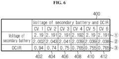
- FIG. 6 is a table for reference in describing the operation in which the apparatus 2 for measuring voltage according to a comparative example of the present disclosure calculates the internal resistance of the secondary battery.
- FIG. 6 shows the exemplary table 400 used for the apparatus 2 for measuring voltage according to a comparative example of the present disclosure to calculate the internal resistance of the secondary battery.
- the table 400 includes a plurality of records 402, 404, 406, 408, 410, 412. Each record may include (i) voltages of the secondary battery before and after charge and discharge, and (ii) DCIR of the secondary battery associated with the voltages of the secondary battery.
- 1 is the voltage of the secondary battery measured before discharge
- 2 is the voltage of the secondary battery measured after discharge
- 3 is the DCIR of the secondary battery associated with the voltages of the secondary battery 10 before and after discharge.
- the first record 402 is a record of the DCIR for the first secondary battery 11.
- the second record 404 is a record of the DCIR for the second secondary battery 12.
- the third to sixth records 406, 408, 410, 412 are records of the DCIR for the third to sixth secondary batteries 13, 14, 15, 16, respectively.
- the deviation in 1 the voltage of the secondary battery measured before discharge is not too large, while large deviation may occur in 2 the voltage of the secondary battery measured after discharge and 3 the DCIR of the secondary battery associated with the voltages of the secondary battery before and after discharge.
- the voltage of the secondary battery measured after discharge is 2.002V
- the second to sixth records 404, 406, 408, 410, 412 showing the distribution of 2.038V to 2.043V the deviation of 0.0385V on the average may occur.
- the DCIR is 0.94 ⁇
- the deviation of 0.1875 ⁇ on the average may occur.
- an error in voltage measurement of the secondary battery occurs, and an error in measurement of the internal resistance calculated based on the voltage of the secondary battery may occur. Additionally, when an error in voltage measurement occurs, an error in estimation of State Of Health (SOH) and State Of Charge (SOC) of the secondary battery may occur.
- SOH State Of Health
- SOC State Of Charge
- FIG. 7 is a schematic flowchart showing a method for measuring voltage according to an embodiment of the present disclosure.
- the subject that performs each step may be each component of the apparatus 2 for measuring voltage according to the present disclosure as previously described.
- the measuring unit 100 receives the voltage across the two ends of each of the plurality of secondary batteries 11, 12, 13, 14, 15, 16 using voltage applied to the reference voltage input terminal V0 as the reference potential.
- the reference voltage input terminal V0 is electrically separated from the reference ground BG electrically connected to the negative terminal MV- of the battery module BM in the apparatus 2.
- the reference potential provided from the reference ground BG is different from the reference potential provided from the reference voltage input terminal V0.
- control unit 200 calculates the DCIR of at least one of the plurality of secondary batteries 11, 12, 13, 14, 15, 16 using the voltage across the two ends of at least one of the plurality of secondary batteries 11, 12, 13, 14, 15, 16 received in the step S100.
- control unit 200 may be implemented as a set of program modules.
- program module may be stored in the memory device and executed by the processor.
- control logics of the control unit there is no particular limitation on the type of control logics of the control unit if at least one of control logics may be combined and the combined control logics may be written in computer-readable coding system to allow the computer to access and read.
- the recording media includes at least one selected from the group consisting of ROM, RAM, register, CD-ROM, magnetic tape, hard disk, floppy disk and an optical data recording device.
- the coding system may be stored and executed in computers connected via a network in distributed manner. Additionally, functional programs, codes and code segments for implementing the combined control logics may be readily inferred by programmers in the technical field to which the present disclosure belongs.
- 'unit' such as 'measuring unit' and 'control unit' is used herein, it refers to a logical component unit, and it is obvious to those skilled in the art that the term does not necessarily indicate a component that may or should be physically separated.
Landscapes
- General Chemical & Material Sciences (AREA)
- Electrochemistry (AREA)
- Chemical & Material Sciences (AREA)
- Chemical Kinetics & Catalysis (AREA)
- Engineering & Computer Science (AREA)
- Physics & Mathematics (AREA)
- General Physics & Mathematics (AREA)
- Manufacturing & Machinery (AREA)
- Power Engineering (AREA)
- Microelectronics & Electronic Packaging (AREA)
- Secondary Cells (AREA)
- Measurement Of Current Or Voltage (AREA)
- Tests Of Electric Status Of Batteries (AREA)
- Charge And Discharge Circuits For Batteries Or The Like (AREA)
- Battery Mounting, Suspending (AREA)
Description
- The present disclosure relates to an apparatus and method for measuring voltage, and more particularly, to an apparatus and method for measuring a voltage of a secondary battery included in a battery module.
- Recently, there is dramatically growing demand for portable electronic products such as laptop computers, video cameras and mobile phones, and with the extensive development of accumulators for energy storage, robots and satellites, many studies are being made on high performance secondary batteries that can be recharged repeatedly.
- Currently, commercially available secondary batteries include nickel-cadmium batteries, nickel-hydrogen batteries, nickel-zinc batteries, lithium secondary batteries and the like, and among them, lithium secondary batteries have little or no memory effect, and thus they are gaining more attention than nickel-based secondary batteries for their advantages of free charging and discharging, a very low self-discharge rate and high energy density.
- Battery packs are used in various fields, and in many cases, they are used in applications requiring large capacity such as electric-drive vehicles or smart grid systems. To increase the capacity of battery packs, there may be a method that increases the capacity of secondary batteries or battery cells themselves, but in this case, the capacity increase effect is not so large, and there is a physical limitation on the size expansion of the secondary batteries. Accordingly, generally, a battery pack including a plurality of battery modules connected in series and in parallel is widely used.
- In many cases, the battery pack includes a Battery Management System (BMS) to manage a battery module. Further, the BMS monitors the temperature, voltage and current of the battery module, and controls the balancing operation, the cooling operation, the charging operation or the discharge operation of the battery pack based on the monitored state of the battery module. For example, when the battery module includes a plurality of secondary batteries, the BMS measures voltage of the plurality of secondary batteries, and estimates Direct Current Internal Resistance (DCIR), State Of Charge (SOC) and State Of Health (SOH) of each secondary battery based on the measured voltage of the secondary batteries.
- In conventional voltage measurement technology, the voltage of each secondary battery is measured using the operating potential of the components within the BMS that is equal to the reference potential for voltage measurement due to the convenience of measurement.
- However, in the case of the conventional voltage measuring apparatus, the charge/discharge current flowing in the charge/discharge path provided in the battery pack flows in the internal components of the BMS, not the charge/discharge path, which causes an error in the measured voltage of the secondary battery and an error in the estimated DCIR, SOC and SOH.
- Further,
WO 2005/109600 A1 is concerned with a system for monitoring cell voltage of a serial connection of battery cells. - The present disclosure is designed to solve the above-described problem, and therefore the present disclosure is directed to providing an apparatus and method for voltage measurement with improved reliability by reducing an error in voltage measurement in the process of measuring the voltage of each secondary battery provided in a battery module.
- These and other objects and advantages of the present disclosure will be understood by the following description and will be apparent from the embodiments of the present disclosure. Further, it will be readily understood that the objects and advantages of the present disclosure can be realized by the means set forth in the appended claims.
- To achieve the above-described object, a battery pack according to the invention is defined in in
claim 1. - A method according to yet another aspect of the present invention is defined in
claim 6. - According to the present disclosure, the reference potential for voltage measurement and the reference potential for operation of the voltage measuring apparatus are electrically separated from each other, and they have different potentials. Additionally, the charge/discharge current flowing through the charge/discharge path does not flow in the voltage measuring apparatus in the voltage measurement process. Accordingly, it is possible to improve the reliability of voltage measurement in the voltage measurement process.
- The present disclosure may have a variety of other effects, and these and other effects can be understood by the following description and will be apparent from the embodiments of the present disclosure.
- The accompanying drawings illustrate a preferred embodiment of the present disclosure, and together with the following detailed description of the present disclosure, serve to provide a further understanding of the technical aspects of the present disclosure, and thus the present disclosure should not be construed as limited to the drawings.
-
FIG. 1 is a schematic diagram showing connection between components of an apparatus for measuring voltage according to an embodiment of the present disclosure and a battery pack. -
FIG. 2 is a schematic diagram showing connection between a BMS printed circuit board including an apparatus for measuring voltage according to an embodiment of the present disclosure and a charge/discharge path of a battery pack. -
FIG. 3 is a table for reference in describing the operation in which an apparatus for measuring voltage according to an embodiment of the present disclosure calculates the internal resistance of a secondary battery. -
FIG. 4 is a schematic diagram showing connection between components of an apparatus for measuring voltage according to a comparative example of the present disclosure and a battery pack. -
FIG. 5 is a diagram for reference in describing a current path formed by an apparatus for measuring voltage according to a comparative example of the present disclosure. -
FIG. 6 is a table for reference in describing the operation in which an apparatus for measuring voltage according to a comparative example of the present disclosure calculates the internal resistance of a secondary battery. -
FIG. 7 is a schematic flowchart showing a method for measuring voltage according to an embodiment of the present disclosure. - Hereinafter, the preferred embodiments of the present disclosure will be described in detail with reference to the accompanying drawings. Prior to the description, it should be understood that the terms or words used in the specification and the appended claims should not be construed as limited to general and dictionary meanings, but interpreted based on the meanings and concepts corresponding to technical aspects of the present disclosure on the basis of the principle that the inventor is allowed to define terms appropriately for the best explanation.
- Therefore, the embodiments described herein and illustrations shown in the drawings are just a most preferred embodiment of the present disclosure, but not intended to fully describe the technical aspects of the present disclosure, so it should be understood that a variety of other equivalents and variations could be made thereto at the time of filing the application.
- Additionally, in describing the present disclosure, when it is deemed that a detailed description of relevant known elements or functions renders the key subject matter of the present disclosure ambiguous, the detailed description is omitted herein.
- Unless the context clearly indicates otherwise, it will be understood that the term "comprises" or "includes" when used in this specification, specifies the presence of stated elements, but does not preclude the presence or addition of one or more other elements. Additionally, the term 'control unit' as used herein refers to a processing unit of at least one function or operation, and this may be implemented in hardware or software alone or in combination.
- In addition, throughout the specification, it will be further understood that when an element is referred to as being "connected to" another element, it can be directly connected to the other element or intervening elements may be present.
- In the specification, a secondary battery may include one unit cell or a plurality of unit cells connected in parallel. The unit cell refers to a physically separable independent cell having a negative terminal and a positive terminal. For example, a pouch-type lithium polymer cell may be regarded as the unit.
-
FIG. 1 is a schematic diagram showing connection between components of an apparatus for measuring voltage according to an embodiment of the present disclosure and abattery pack 1. - Referring to
FIG. 1 , thebattery pack 1 includes a battery module BM, a first power terminal Pack +, a second power terminal Pack -, anapparatus 2, and may include acurrent sensor 70. Particularly, the battery module BM and thecurrent sensor 70 may be connected in series on the charge/discharge path electrically connecting the first power terminal Pack + of thebattery pack 1 to the second power terminal Pack - of thebattery pack 1. For example, as shown in the configuration ofFIG. 1 , the first power terminal Pack + of thebattery pack 1 may be connected to the positive terminal of the battery module BM, and the negative terminal MV- of the battery module BM may be connected to one end of thecurrent sensor 70. Additionally, the other end of thecurrent sensor 70 may be connected to the second power terminal Pack - of thebattery pack 1. Thecurrent sensor 70 may be a shunt resistor. Hereinafter, for convenience of description, assume that the battery module BM includes sixsecondary batteries 10. Of course, the number ofsecondary batteries 10 included in the battery module BM may be greater or less than six. - The battery module BM includes a plurality of
secondary batteries secondary batteries FIG. 1 , the plurality ofsecondary batteries - As shown in the configuration of
FIG. 1 , the busbar B connects one end (e.g., the negative terminal) of at least one of the plurality ofsecondary batteries secondary battery 11 to the negative terminal MV-of the battery module BM in series. Here, the busbar B may have resistance, namely, the resistance component that impedes the flow of current. For example, the busbar B may be disposed between one end of thesecondary battery 11 and the negative terminal MV- of the battery module BM. The busbar B may be a conductive metal plate. - As shown in the configuration of
FIG. 1 , theapparatus 2 includes ameasuring unit 100 and acontrol unit 200. Themeasuring unit 100 includes a plurality of voltage input terminals V0, V1, V2, V3, V4, V5, V6 and a first ground terminal G1. - The plurality of voltage input terminals V0, V1, V2, V3, V4, V5, V6 may be electrically connected to two ends of each of the plurality of
secondary batteries secondary batteries apparatus 2. The voltage input terminal V0 may be also referred to as a reference voltage input terminal, and is electrically connected to a node N0 which is a point of connection between the negative terminal of thesecondary battery 11 and the busbar B through the wire with the reference wire resistance R0. The voltage input terminal V1 is electrically connected to a node N1 which is a point of connection between the positive terminal of thesecondary battery 11 and the negative terminal of thesecondary battery 12 through the wire with the first wire resistance R1. The voltage input terminal V2 is electrically connected to a node N2 which is a point of connection between the positive terminal of thesecondary battery 12 and the negative terminal of thesecondary battery 13 through the wire with the second wire resistance R2. The voltage input terminal V3 is electrically connected to a node N3 which is a point of connection between the positive terminal of thesecondary battery 13 and the negative terminal of thesecondary battery 14 through the wire with the third wire resistance R3. The voltage input terminal V4 is electrically connected to a node N4 which is a point of connection between the positive terminal of thesecondary battery 14 and the negative terminal of thesecondary battery 15 through the wire with the fourth wire resistance R4. The voltage input terminal V5 is electrically connected to a node N5 which is a point of connection between the positive terminal of thesecondary battery 15 and the negative terminal of thesecondary battery 16 through the wire with the fifth wire resistance R5. The voltage input terminal V6 is electrically connected to a node N6 which is a point of connection between the positive terminal of thesecondary battery 16 and the plus terminal Pack + through the wire with the sixth wire resistance R6. The node N0 may be also referred to as a second reference ground. - Accordingly, the plurality of voltage input terminals V0, V1, V2, V3, V4, V5, V6 may receive the voltages across the two ends of the plurality of
secondary batteries secondary batteries FIG. 1 , the reference voltage input terminal V0 may be electrically connected to the second reference ground N0 through the wire with the reference wire resistance R0 to receive the voltage applied to the second reference ground N0 as second reference potential. Similarly, the first voltage input terminal V1 may receive the voltage applied to the first node N1 from the first node N1. Similarly, the second voltage input terminal V2 may receive the voltage applied to the second node N2 from the second node N2. Similarly, the third voltage input terminal V3 may receive the voltage applied to the third node N3 from the third node N3. Similarly, the fourth voltage input terminal V4 may receive the voltage applied to the fourth node N4 from the fourth node N4. Similarly, the fifth voltage input terminal V5 may receive the voltage applied to the fifth node N5 from the fifth node N5. Similarly, the sixth voltage input terminal V6 may receive the voltage applied to the sixth node N6 from the sixth node N6. - The first ground terminal G1 is electrically connected to a reference ground BG electrically connected to the negative terminal MV- of the battery module BM. The reference ground BG may be electrically connected to the negative terminal MV- of the battery module BM through a wire with resistance RG. Particularly, the first ground terminal G1 is directly connected to the reference ground BG. Through this configuration, the measuring
unit 100 operates with the potential of the reference ground BG as operating reference potential (also referred to as 'first reference potential'). - Preferably, the measuring
unit 100 may further include a plurality of current measurement terminals K1, K2. The plurality of current measurement terminals K1, K2 may be connected to two ends of thecurrent sensor 70 connected to the battery module BM to receive the voltage across the two ends of thecurrent sensor 70. That is, the plurality of current measurement terminals K1, K2 may be connected to two ends of thecurrent sensor 70 to receive the voltage across the two ends of thecurrent sensor 70 from the two ends of thecurrent sensor 70. In an embodiment, the measuringunit 100 may measure the direction, magnitude or amount of the current flowing in thecurrent sensor 70 using the voltage across the two ends of thecurrent sensor 70. For example, the measuringunit 100 may measure the current flowing in thecurrent sensor 70 by substituting the pre-stored resistance of thecurrent sensor 70 and the voltage across the two ends of thecurrent sensor 70 into the Ohm's law. - The
control unit 200 receives a voltage signal indicating the voltage across the two ends of each of the plurality ofsecondary batteries unit 100. That is, thecontrol unit 200 is operably coupled to the measuringunit 100 to receive a voltage signal indicating the voltage across the two ends of the plurality ofsecondary batteries unit 100. Particularly, thecontrol unit 200 may receive the voltage signal indicating the voltage across the two ends of each of the plurality ofsecondary batteries unit 100 in a preset cycle. - Preferably, the
control unit 200 may receive the voltage across the two ends of each of the plurality ofsecondary batteries current sensor 70 from the measuringunit 100. Particularly, thecontrol unit 200 may receive the voltage across the two ends of each of the plurality ofsecondary batteries current sensor 70 measured at the same measurement time or in the same measurement cycle from the measuringunit 100. Particularly, thecontrol unit 200 receives the voltage signal indicating the voltage across the two ends of each of the plurality ofsecondary batteries current sensor 70 measured at the same time due to the synchronized measurement time or measurement cycle from the measuringunit 100. - Additionally, the
control unit 200 may calculate a voltage value of each of the plurality ofsecondary batteries secondary batteries control unit 200 may calculate a voltage value of thesecondary battery 12 based on a voltage difference between two voltage input terminals (e.g., V2, V1). - Additionally, the
control unit 200 may calculate a current value using the voltage across the two ends of thecurrent sensor 70. For example, thecontrol unit 200 may calculate a current value by substituting the pre-stored resistance of thecurrent sensor 70 and the voltage across the two ends of thecurrent sensor 70 into the Ohm's law. - Additionally, the
control unit 200 may calculate Direct Current Internal Resistance (DCIR) of at least one of the plurality ofsecondary batteries secondary batteries control unit 200 may calculate the DCIR of thesecondary battery 10 using the voltage across the two ends of thesecondary battery 10 before and after charge and discharge and an amount of the current flowing in thecurrent sensor 70. For example, thecontrol unit 200 may calculate the DCIR using the followingEquation 1.
- Here, DCIRi denotes the DCIR of the secondary battery 1i, I denotes the magnitude of the current flowing through the
current sensor 70, CViA denotes the voltage across the two ends of the secondary battery 1i measured while the current does not flow through thecurrent sensor 70, and CViB denotes the voltage across the two ends of the secondary battery 1i measured while I flows through thecurrent sensor 70. - Additionally, the
control unit 200 includes a second ground terminal G2. The second ground terminal G2 is electrically connected to the reference ground BG electrically connected to the negative terminal MV- of the battery module BM. Particularly, the second ground terminal G2 may be directly connected to the reference ground BG. Through this configuration, thecontrol unit 200 may operate with the potential of the reference ground BG as the reference operating potential. - Additionally, the reference voltage input terminal V0 is electrically connected to the second reference ground N0 connected to one end of the busbar B.
- Particularly, the reference voltage input terminal V0 may be connected to the second reference ground N0 directly connected to one end of the busbar B to receive the voltage applied to the second reference ground N0.
- The measuring
unit 100 may measure the voltage across the two ends of each of the plurality ofsecondary batteries unit 100 may measure voltage of eachsecondary battery - For example, the voltage of the first
secondary battery 11 is a potential difference between the second reference ground N0 and the first node N1, and may be measured using a potential difference between the reference voltage input terminal V0 and the first voltage input terminal V1. Similarly, the voltage of the secondsecondary battery 12 is a potential difference between the first node N1 and the second node N2, and may be measured using a potential difference between the first voltage input terminal V1 and the second voltage input terminal V2. Similarly, the voltage of the thirdsecondary battery 13 is a potential difference between the second node N2 and the third node N3, and may be measured using a potential difference between the second voltage input terminal V2 and the third voltage input terminal V3. Similarly, the voltage of the fourthsecondary battery 14 is a potential difference between the third node N3 and the fourth node N4, and may be measured using a potential difference between the third voltage input terminal V3 and the fourth voltage input terminal V4. Similarly, the voltage of the fifthsecondary battery 15 is a potential difference between the fourth node N4 and the fifth node N5, and may be measured using a potential difference between the fourth voltage input terminal V4 and the fifth voltage input terminal V5. Similarly, the voltage of the sixthsecondary battery 16 is a potential difference between the fifth node N5 and the sixth node N6, and may be measured using a potential difference between the fifth voltage input terminal V5 and the sixth voltage input terminal V6. - Particularly, the reference voltage input terminal V0 is electrically separated from the reference ground BG within the
apparatus 2. Additionally, the reference voltage input terminal V0 and the reference ground BG have different reference potentials from each other. This will be described in detail in the description ofFIG. 2 . - Meanwhile, the
control unit 200 may be implemented such that it selectively includes a processor, an Application-Specific Integrated Circuit, a chipset, a logic circuit, a register, a communication modem and/or a data processing device known in the art to perform the operation as described above. - Preferably, the
control unit 200 may include a memory device. The memory device is not limited to a particular type and includes any storage medium capable of recording and erasing information. For example, the memory device may be RAM, ROM, register, hard disk, optical recording media or magnetic recording media. The memory device may be electrically connected to thecontrol unit 200 through, for example, data bus to allow thecontrol unit 200 to access it. The memory device may store and/or update and/or erase and/or transmit programs including various types of control logics executed by thecontrol unit 200 and/or data created when the control logics are executed. The memory device may be logically split into two or more. -
FIG. 2 is a schematic diagram showing connection between theapparatus 2 for voltage measurement according to an embodiment of the present disclosure and the charge/discharge path of thebattery pack 1. Here, difference(s) between this embodiment and the previous embodiment will be primarily described, and a description, to which the description of the previous embodiment may be equally or similarly applied, is omitted herein. - Referring to
FIGS. 1 and2 , theapparatus 2 according to the present disclosure may include a printed circuit board P. Particularly, the printed circuit board P may be electrically connected to the charge/discharge path L of thebattery pack 1. For example, as shown inFIG. 2 , the second reference ground N0 may be a contact point at which one end of the busbar B disposed on the charge/discharge path L and a first wire L1 are connected in common. Additionally, the negative terminal MV- of the battery module BM may be a contact point at which the other end of the busbar B on the charge/discharge path L and a second wire L2 are connected in common. Here, the first wire L1 may be the wire electrically connecting the reference voltage input terminal V0 on the printed circuit board P to the second reference ground N0. Additionally, the second wire L2 may be the wire electrically connecting the reference ground BG on the printed circuit board P to the negative terminal MV- of the battery module. The first wire L1 may have the resistance R0. The second wire L2 may have the resistance RG. - Preferably, the reference potential for sensing the voltage across the two ends of each of the plurality of
secondary batteries components apparatus 2 may be applied to the reference ground BG. Further, theapparatus 2 may be included in a battery management system (BMS). Other components of the BMS such as a Micro Controller Unit (MCU) may also operate at the reference potential applied from the reference ground BG. Particularly, the reference voltage input terminal V0 may have the voltage applied to the second reference ground N0 connected to one end of the busbar B as the reference potential, and the reference ground BG may have the voltage applied to the negative terminal MV- of the battery module connected to the other end of the busbar B as the reference potential. - Here, the component of the BMS may be mounted in the printed circuit board P in the form of a chip or circuit. For example, the reference ground BG may be mounted in the printed circuit board P by soldering onto the circuit. Alternatively, the reference voltage input terminal V0 may come into contact with the printed circuit board P. For example, the printed circuit board P may be a Printed Circuit Board (PCB).
- Particularly, the first wire L1 and the second wire L2 may be electrically separated from each other on the printed circuit board P. That is, the first wire L1 and the second wire L2 may be configured such that they are electrically separated from each other on the printed circuit board P.
- Preferably, the first wire L1 and the second wire L2 may be configured to prevent the charge/discharge current from flowing on. In detail, the first wire L1 and the second wire L2 may be electrically isolated from each other on the printed circuit board P so that the first wire L1 and the second wire L2 may be separated from each other to prevent the current from flowing between. That is, the reference voltage input terminal V0 may be electrically connected to the second reference ground N0 through the first wire L1, and the reference ground BG may be electrically connected to the negative terminal MV- of the battery module through the second wire L2 electrically separated from the first wire L1 in the BMS. Through this configuration, as opposed to the conventional art, the
apparatus 2 has no path of current that flows into the BMS through the charge/discharge path during charging and discharging, and may provide electrical isolation between the charge/discharge path and the BMS. - For example, as shown in the configuration of
FIG. 2 , the apparatus 2e may have the first wire L1 and the second wire L2 electrically separated from each other on the printed circuit board P for electrical isolation between the charge/discharge path L and the BMS to prevent the current from flowing from the charge/discharge path L into the BMS. For example, the charge/discharge current passing through the second reference ground N0 on the charge/discharge path L flows in the busbar B, not the first wire L1. Additionally, the charge/discharge current passing through the busbar B does not flow in the second wire L2, and instead, flows through the negative terminal MV- of the battery module. -
FIG. 3 is a table for reference in describing the operation in which theapparatus 2 for measuring voltage according to an embodiment of the present disclosure calculates the internal resistance of the secondary battery. - Referring to
FIGS. 1 and3 , theapparatus 2 may calculate the internal resistance of the secondary battery. Preferably, the memory device may include a table 300 used to calculate the internal resistance of the secondary battery. The table 300 includes a plurality ofrecords FIG. 3 , ① is the voltage of the secondary battery measured while the discharge current does not flow, ② is the voltage of the secondary battery measured while the discharge current flows, and ③ is the DCIR of the secondary battery associated with the voltages of the secondary battery before and after discharge. For example, thefirst record 302 is a record for the DCIR of the firstsecondary battery 11. Additionally, thesecond record 304 is a record for the DCIR of the secondsecondary battery 12. Likewise, the third tosixth records secondary batteries - Particularly, the plurality of
records - For example, referring to the
first record 302, the voltage of the secondary battery measured before discharge is 2.330V, and the deviation between thefirst record 302 and the second tosixth records first record 302 and the second tosixth records first record 302 and the second tosixth records - The
apparatus 2 may accurately measure the internal resistance of the secondary battery without large deviation in the internal resistance for each secondary battery. In detail, theapparatus 2 may achieve accurate voltage measurement of the secondary battery during charging and discharging of the secondary battery. Accordingly, it is possible to improve the reliability of estimation of State Of Health (SOH) and State Of Charge (SOC) of the secondary battery performed by the MCU included in the BMS. - The
apparatus 2 may be included in the BMS. In this configuration, at least some of the components of theapparatus 2 for measuring voltage according to the present disclosure may be implemented by supplementing or adding the functions of the components included in the conventional BMS. For example, the measuring unit and the control unit of theapparatus 2 may be implemented as the components of the BMS. -
FIG. 4 is a schematic diagram showing connection between components of theapparatus 2 for measuring voltage according to a comparative example of the present disclosure and thebattery pack 1.FIG. 5 is a diagram for reference in describing a current path formed by theapparatus 2 for measuring voltage according to a comparative example of the present disclosure. A detailed description to which the description of the connection between the components of theapparatus 2 for measuring voltage and thebattery pack 1 as described inFIG. 1 may be equally or similarly applied is omitted herein, and difference(s) between this embodiment and the previous embodiment will be primarily described. - Referring to
FIGS. 4 and5 , theapparatus 2 for measuring voltage according to a comparative example of the present disclosure may be configured to allow the current to flow between the charge/discharge path L of thebattery pack 1 and the BMS. In detail, theapparatus 2 for measuring voltage according to a comparative example of the present disclosure may have a current path on the printed circuit board P, through which the current transmitted from the charge/discharge path L flows. For example, as shown in the configuration ofFIGS. 4 and5 , theapparatus 2 for measuring voltage according to a comparative example of the present disclosure may have the reference voltage input terminal V0 and the reference ground BG electrically connected to each other. In detail, the reference voltage input terminal V0 and the reference ground BG may be electrically connected to each other on the printed circuit board P. Here, there may be pattern resistance RP between the reference voltage input terminal V0 and the reference ground BG. That is, the pattern resistance RP may be resistance of a pattern or circuit connecting the reference voltage input terminal V0 to the reference ground BG on the printed circuit board P. - Additionally, the
apparatus 2 for measuring voltage according to a comparative example of the present disclosure may have the first wire L1 and the second wire L2 through which the current flows during charging and discharging. For example, as shown in the configuration ofFIG. 5 , two current paths I1, I2 may be formed, through which the current may flow from the second reference ground N0 to the negative terminal MV- of the battery module. In detail, a first path I1 passing through the first wire L1 and the second wire L2 and a second path I2 passing through the busbar B may be formed. - Here, referring to
FIGS. 1 and4 , in the case of theapparatus 2 as shown inFIG. 1 , the voltage of the firstsecondary battery 11 measured through a potential difference between the reference voltage input terminal V0 and the first voltage input terminal V1 may be calculated using the followingEquation 2.
- In
Equation 2, V1 is the voltage applied to the first voltage input terminal V1, V0 is the voltage applied to the reference voltage input terminal V0, and CV1 is the voltage across the two ends of the firstsecondary battery 11. That is, theapparatus 2 for measuring voltage according to an embodiment of the present disclosure as shown inFIG. 1 does not have an error in voltage measurement. - In the case of the
apparatus 2 for measuring voltage according to a comparative example of the present disclosure as shown inFIG. 4 , the voltage of the firstsecondary battery 11 measured through a potential difference between the reference voltage input terminal V0 and the first voltage input terminal V1 may be calculated using the followingEquation 3.
- Here, V1 is the voltage applied to the first voltage input terminal V1, V0 is the voltage applied to the reference voltage input terminal V0, CV1 is the voltage across the two ends of the first
secondary battery 11, and VB is the voltage applied to the two ends of the busbar B. Referring toFIG. 5 together, due to the formation of the current path I1 flowing in the first wire L1 and the second wire L2, the voltage applied to the reference voltage input terminal V0 is affected by a voltage drop by the resistance R0, and consequently, theapparatus 2 for measuring voltage according to a comparative example of the present disclosure as shown inFIG. 4 has an error in voltage measurement -
FIG. 6 is a table for reference in describing the operation in which theapparatus 2 for measuring voltage according to a comparative example of the present disclosure calculates the internal resistance of the secondary battery. -
FIG. 6 shows the exemplary table 400 used for theapparatus 2 for measuring voltage according to a comparative example of the present disclosure to calculate the internal resistance of the secondary battery. The table 400 includes a plurality ofrecords FIGS. 4 and6 , ① is the voltage of the secondary battery measured before discharge, ② is the voltage of the secondary battery measured after discharge, and ③ is the DCIR of the secondary battery associated with the voltages of thesecondary battery 10 before and after discharge. For example, thefirst record 402 is a record of the DCIR for the firstsecondary battery 11. Additionally, thesecond record 404 is a record of the DCIR for the secondsecondary battery 12. Likewise, the third tosixth records secondary batteries - Particularly, when comparing the
first record 402 of the plurality ofrecords sixth records - For example, referring to the
first record 402, the voltage of the secondary battery measured after discharge is 2.002V, and when compared with the second tosixth records first record 402, the DCIR is 0.94Ω, and when compared with the second tosixth records - Accordingly, in the case of the
apparatus 2 for measuring voltage according to a comparative example of the present disclosure, an error in voltage measurement of the secondary battery occurs, and an error in measurement of the internal resistance calculated based on the voltage of the secondary battery may occur. Additionally, when an error in voltage measurement occurs, an error in estimation of State Of Health (SOH) and State Of Charge (SOC) of the secondary battery may occur. -
FIG. 7 is a schematic flowchart showing a method for measuring voltage according to an embodiment of the present disclosure. InFIG. 7 , the subject that performs each step may be each component of theapparatus 2 for measuring voltage according to the present disclosure as previously described. - As shown in
FIG. 7 , in step S100, the measuringunit 100 receives the voltage across the two ends of each of the plurality ofsecondary batteries apparatus 2. The reference potential provided from the reference ground BG is different from the reference potential provided from the reference voltage input terminal V0. - In step S100, the
control unit 200 calculates the DCIR of at least one of the plurality ofsecondary batteries secondary batteries - Additionally, when the control logics are implemented in software, the
control unit 200 may be implemented as a set of program modules. In this instance, the program module may be stored in the memory device and executed by the processor. - Additionally, there is no particular limitation on the type of control logics of the control unit if at least one of control logics may be combined and the combined control logics may be written in computer-readable coding system to allow the computer to access and read. For example, the recording media includes at least one selected from the group consisting of ROM, RAM, register, CD-ROM, magnetic tape, hard disk, floppy disk and an optical data recording device. Additionally, the coding system may be stored and executed in computers connected via a network in distributed manner. Additionally, functional programs, codes and code segments for implementing the combined control logics may be readily inferred by programmers in the technical field to which the present disclosure belongs.
- While the present disclosure has been hereinabove described with regard to a limited number of embodiments and drawings, the present disclosure is not limited thereto and various modifications and changes may be made by those skilled in the art within the scope of the appended claims.
- Although the term 'unit' such as 'measuring unit' and 'control unit' is used herein, it refers to a logical component unit, and it is obvious to those skilled in the art that the term does not necessarily indicate a component that may or should be physically separated.
Claims (6)
- A battery pack (1) comprising a battery module (BM), a first power terminal (pack+), a second power terminal (pack-) and an apparatus (2),whereby the apparatus is connected to the battery module,whereby the battery module (BM) includesa positive terminal,a negative terminal (MV-),a plurality of secondary batteries (11, 12, 13, 14, 15, 16) connected in series in a sequential order between the positive terminal and the negative terminal (MV-), anda busbar (B), wherein the busbar (B) connects one end of at least one of the plurality of secondary batteries (11, 12, 13, 14, 15, 16) to a negative terminal (MV-) of the battery module (BM),wherein the apparatus is configured for measuring a voltage of each of the plurality of secondary batteries (11, 12, 13, 14, 15, 16),
the apparatus comprising:a measuring unit (100) including a plurality of voltage input terminals (V0-V6) electrically connected to two ends of each of the plurality of secondary batteries (11, 12, 13, 14, 15, 16) to receive the voltage across the two ends of each of the plurality of secondary batteries (11, 12, 13, 14, 15, 16), and a first ground terminal (G1) electrically directly connected to a first reference ground (BG), whereby said first reference ground (BG) is electrically connected to the negative terminal (MV-) of the battery module (BM); anda control unit (200) configured to receive the voltage across the two ends of each of the plurality of secondary batteries (11, 12, 13, 14, 15, 16) from the measuring unit (100), and including a second ground terminal (G2) electrically connected to the first reference ground (BG),wherein one of the plurality of voltage input terminals (V0-V6) is a reference voltage input terminal (V0) electrically connected to a second reference ground (N0) connected to one end of the busbar (B) to receive voltage applied to the second reference ground (N0), and wherein the reference voltage input terminal (V0) is electrically separated from the first reference ground (BG) so that the reference voltage input terminal (V0) and the first reference ground (BG) have different reference potentials,wherein the reference voltage input terminal (V0) is connected to the second reference ground (N0) through a first wire (L1) with a reference wire resistance (R0), the first reference ground (BG) is connected to the negative terminal (MV-) of the battery module (BM) through a second wire (L2) with a second wire resistance (RG), said second wire (L2) being electrically separated from said first wire (L1),wherein the one end of the busbar is directly connected to the second reference ground (N0), and the other end of the busbar is directly connected to the negative terminal (MV-) of the battery module (BM). - The battery pack according to claim 1, wherein the control unit (200) is further configured to calculate a direct current internal resistance of at least one of the plurality of secondary batteries (11, 12, 13, 14, 15, 16) using the voltage across the two ends of the at least one of the plurality of secondary batteries (11, 12, 13, 14, 15, 16).
- The battery pack according to claim 1, wherein the reference voltage input terminal (V0) has a voltage applied to the second reference ground (N0) connected to the one end of the busbar (B) as the reference potential of the reference voltage input terminal (V0), and
the first reference ground (BG) has a voltage applied to the negative terminal (MV-) of the battery module (BM) connected to the other end of the busbar (B as the reference potential of the first reference ground (BG). - The battery pack according to claim 1, wherein the first wire (L1) and the second wire (L2) are electrically separated from each other on a printed circuit board, so that
the first wire (L1) and the second wire (L2) are configured to prevent a charge/discharge current from flowing. - The battery pack according to claim 1, wherein the measuring unit (100) includes a plurality of current measurement terminals (K1, K2) connected to two ends of a current sensor (70) connected to the battery module (BM) to receive voltage across the two ends of the current sensor (70), wherein the battery module (BM) and the current sensor (70) are connected in series on the charge/discharge path electrically connecting the first power terminal (pack+) to the second power terminal (pack-);
and
the control unit (200) is configured to:receive the voltage across the two ends of each of the plurality of secondary batteries (11, 12, 13, 14, 15, 16) and the voltage across the two ends of the current sensor (70) measured at a same measurement time from the measuring unit (100);calculate a voltage value of each of the plurality of secondary batteries (11, 12, 13, 14, 15, 16) based on the voltage across the two ends of each of the plurality of secondary batteries (11, 12, 13, 14, 15, 16); andcalculate a current value based on the voltage across the two ends of the current sensor (70),wherein one of the plurality of voltage input terminals (V0-V6) is a reference voltage input terminal (V0) electrically separated from a first reference ground (BG) so that the reference voltage input terminal (V0) and a first reference ground (BG) have different reference potentials. - A method for measuring a voltage of each of a plurality of secondary batteries (11, 12, 13, 14, 15, 16) using the battery pack according to any one of claims 1 to 5.
Applications Claiming Priority (2)
| Application Number | Priority Date | Filing Date | Title |
|---|---|---|---|
| KR1020170172491A KR102256602B1 (en) | 2017-12-14 | 2017-12-14 | Apparatus and method for measuring voltage |
| PCT/KR2018/014210 WO2019117487A1 (en) | 2017-12-14 | 2018-11-19 | Voltage measurement device and method |
Publications (3)
| Publication Number | Publication Date |
|---|---|
| EP3667343A1 EP3667343A1 (en) | 2020-06-17 |
| EP3667343A4 EP3667343A4 (en) | 2020-10-21 |
| EP3667343B1 true EP3667343B1 (en) | 2024-06-26 |
Family
ID=66819407
Family Applications (1)
| Application Number | Title | Priority Date | Filing Date |
|---|---|---|---|
| EP18887333.5A Active EP3667343B1 (en) | 2017-12-14 | 2018-11-19 | Apparatus and method for measuring voltage |
Country Status (9)
| Country | Link |
|---|---|
| US (1) | US11215669B2 (en) |
| EP (1) | EP3667343B1 (en) |
| JP (2) | JP2020521963A (en) |
| KR (1) | KR102256602B1 (en) |
| CN (1) | CN110832332B (en) |
| ES (1) | ES2985277T3 (en) |
| HU (1) | HUE067444T2 (en) |
| PL (1) | PL3667343T3 (en) |
| WO (1) | WO2019117487A1 (en) |
Families Citing this family (6)
| Publication number | Priority date | Publication date | Assignee | Title |
|---|---|---|---|---|
| RU2732404C2 (en) | 2014-09-26 | 2020-09-16 | Ф. Хоффманн-Ля Рош Аг | Methods of producing (cyclopentyl[d]pyrimidin-4-yl)piperazine compounds |
| KR102895997B1 (en) * | 2016-12-15 | 2025-12-03 | 현대자동차주식회사 | Battery system and method for controlling the same |
| JP7379664B2 (en) * | 2019-08-12 | 2023-11-14 | 深▲セン▼市麦格松▲電▼▲気▼科技有限公司 | Rechargeable battery discharge control method, charging control method, and rechargeable battery |
| KR102930126B1 (en) * | 2020-10-14 | 2026-02-25 | 주식회사 엘지에너지솔루션 | Battery apparatus |
| KR102946922B1 (en) * | 2021-08-03 | 2026-04-02 | 주식회사 엘지에너지솔루션 | Battery management apparatus and method |
| WO2025115506A1 (en) * | 2023-11-30 | 2025-06-05 | Fdk株式会社 | Battery management system, management device, cycle setting method, and program |
Family Cites Families (60)
| Publication number | Priority date | Publication date | Assignee | Title |
|---|---|---|---|---|
| JPS51112473A (en) * | 1975-03-28 | 1976-10-04 | Nippon Aluminium Mfg | Method of making compound structure of metals |
| US5744962A (en) * | 1995-03-14 | 1998-04-28 | Alber; Glenn | Automated data storing battery tester and multimeter |
| KR200158902Y1 (en) | 1996-12-06 | 1999-10-15 | 유기범 | Overcharge prevention apparatus of terminal for personal communication |
| US6313637B1 (en) | 1997-11-20 | 2001-11-06 | Denso Corporation | Voltage detecting device for set battery |
| GB0410531D0 (en) * | 2004-05-12 | 2004-06-16 | Arbarr Electronics Ltd | Voltage monitoring system |
| DE102005029096A1 (en) | 2005-06-23 | 2007-01-04 | Robert Bosch Gmbh | Battery condition detection for car batteries |
| JP4883956B2 (en) * | 2005-08-04 | 2012-02-22 | 日立オートモティブシステムズ株式会社 | Battery cell voltage measuring device |
| JP5008863B2 (en) * | 2005-11-30 | 2012-08-22 | プライムアースEvエナジー株式会社 | Secondary battery control device, secondary battery deterioration determination method using secondary battery temperature estimation method |
| DE102007048164B4 (en) | 2007-10-08 | 2013-01-17 | Siemens Aktiengesellschaft | A method for contactless transmission of at least one differential signal between a transmitter and a receiver in the presence of at least one common mode noise signal and associated circuitry |
| DE102007049528B4 (en) | 2007-10-15 | 2009-06-25 | Panasonic Electronic Devices Europe Gmbh | Method and device for measuring cell voltages in a plurality of battery cells connected in series |
| JP5065000B2 (en) * | 2007-12-28 | 2012-10-31 | 三洋電機株式会社 | Voltage measuring device and assembled battery system including the same |
| JP5549121B2 (en) | 2008-06-17 | 2014-07-16 | 三洋電機株式会社 | BATTERY VOLTAGE DETECTION DEVICE AND BATTERY SYSTEM HAVING THE SAME |
| WO2010056303A1 (en) | 2008-11-12 | 2010-05-20 | Bravo Zulu International Ltd. | Lead acid battery de-sulfation |
| WO2010062141A2 (en) * | 2008-11-27 | 2010-06-03 | 주식회사 엘지화학 | Apparatus and method for monitoring cell voltage of battery pack |
| WO2010113455A1 (en) * | 2009-03-31 | 2010-10-07 | 三洋電機株式会社 | Battery module, battery system, and electric vehicle |
| JP5390925B2 (en) * | 2009-04-24 | 2014-01-15 | パナソニック株式会社 | Battery pack |
| JP2010257775A (en) * | 2009-04-24 | 2010-11-11 | Sanyo Electric Co Ltd | Battery module, battery system and electric vehicle |
| KR101156342B1 (en) * | 2009-08-03 | 2012-06-13 | 삼성에스디아이 주식회사 | Battery id setting system and driving method thereof |
| JP5634694B2 (en) * | 2009-09-24 | 2014-12-03 | 本田技研工業株式会社 | Voltage detector |
| KR101106353B1 (en) | 2009-11-23 | 2012-01-18 | 삼성에스디아이 주식회사 | Battery pack and its voltage sensing method |
| JP5382138B2 (en) * | 2009-12-25 | 2014-01-08 | トヨタ自動車株式会社 | Abnormality detection device for battery pack |
| JPWO2011105095A1 (en) * | 2010-02-24 | 2013-06-20 | 三洋電機株式会社 | Battery module, battery system, electric vehicle, moving object, power storage device, power supply device, and electric device |
| JP5700756B2 (en) * | 2010-04-28 | 2015-04-15 | 矢崎総業株式会社 | Voltage measurement device for multiple assembled batteries |
| US8933702B2 (en) * | 2010-05-14 | 2015-01-13 | Liebert Corporation | Battery monitor with correction for internal OHMIC measurements of battery cells in parallel connected battery strings |
| JP2012016174A (en) * | 2010-06-30 | 2012-01-19 | Sanyo Electric Co Ltd | Power supply device for vehicle |
| JP5638311B2 (en) | 2010-08-18 | 2014-12-10 | ラピスセミコンダクタ株式会社 | Battery pack system, voltage monitoring system, voltage monitoring device, and semiconductor device |
| WO2012029231A1 (en) * | 2010-08-30 | 2012-03-08 | 三洋電機株式会社 | Voltage detection circuit and battery system equipped with same, electric vehicle, moving body, electric power storage device, and power supply device |
| US8803477B2 (en) * | 2010-09-21 | 2014-08-12 | Electricab Corporation | Battery module for high-current rapid charging |
| KR101182431B1 (en) * | 2010-10-12 | 2012-09-12 | 삼성에스디아이 주식회사 | Battery pack, controlling method of the same, and power storage system including the battery pack |
| US9041359B2 (en) * | 2011-03-10 | 2015-05-26 | Samsung Sdi Co., Ltd. | Battery pack with integral non-contact discharging means and electronic device including the same |
| JP5333619B2 (en) | 2011-03-30 | 2013-11-06 | 株式会社デンソー | Voltage detection device and coupling circuit |
| JP2012220344A (en) * | 2011-04-08 | 2012-11-12 | Fujitsu Ten Ltd | Cell voltage measurement device |
| EP2700958B1 (en) | 2011-04-21 | 2019-01-16 | Renesas Electronics Corporation | Switch circuit, selection circuit, and voltage measurement device |
| FR2976675B1 (en) | 2011-06-16 | 2013-07-12 | Nanotec Solution | INTEGRATED CAPACITIVE MEASUREMENT CIRCUIT WITH FLOATING BRIDGE. |
| CN102393489B (en) * | 2011-09-30 | 2013-10-16 | 北京汽车新能源汽车有限公司 | On-line monitoring control method of electric car power cell high voltage loop resistor and apparatus thereof |
| KR101527546B1 (en) * | 2011-11-14 | 2015-06-09 | 주식회사 엘지화학 | Battery management system and battery pack protection apparatus including the same |
| KR20130068986A (en) * | 2011-12-16 | 2013-06-26 | (주)브이이엔에스 | An apparatus for measuring a high voltage of electronic vehecle |
| CN103293355B (en) * | 2012-02-24 | 2016-06-08 | 东莞钜威新能源有限公司 | A kind of tension measuring circuit |
| KR101397026B1 (en) * | 2012-03-12 | 2014-05-20 | 삼성에스디아이 주식회사 | Battery system and energy storage system including same |
| US9065296B2 (en) * | 2012-04-03 | 2015-06-23 | Samsung Sdi Co., Ltd. | Battery pack, method of measuring voltage of the battery pack, and energy storage system including the battery pack |
| US10180460B1 (en) * | 2012-04-20 | 2019-01-15 | Motiv Power Systems, Inc. | Performing active interrogation of battery packs in situ to obtain precise SOC and SOH estimates |
| JP5874560B2 (en) * | 2012-07-25 | 2016-03-02 | 株式会社デンソー | Battery temperature calculation device |
| JP5907050B2 (en) | 2012-12-10 | 2016-04-20 | 株式会社デンソー | Battery system |
| JP5991299B2 (en) * | 2012-12-26 | 2016-09-14 | 株式会社デンソー | Voltage detection device for battery pack |
| KR20140086461A (en) | 2012-12-28 | 2014-07-08 | 엘지전자 주식회사 | Apparatus for checking a battery module |
| KR20140095781A (en) * | 2013-01-25 | 2014-08-04 | 엘지전자 주식회사 | An apparatus for measuring a high voltage of electronic vehecle |
| JP5942882B2 (en) * | 2013-02-15 | 2016-06-29 | 株式会社デンソー | Battery system |
| JP6376722B2 (en) | 2013-02-15 | 2018-08-22 | エイブリック株式会社 | Battery voltage detection circuit |
| JP5997081B2 (en) | 2013-03-21 | 2016-09-21 | プライムアースEvエナジー株式会社 | Secondary battery state estimation device and secondary battery state estimation method |
| EP2884662B1 (en) * | 2013-12-13 | 2019-06-26 | Power Integrations Switzerland GmbH | Device and method for detecting a short-circuit or excess current condition in a semiconductor power switch |
| JP6312508B2 (en) | 2014-04-11 | 2018-04-18 | 日立オートモティブシステムズ株式会社 | Battery monitoring device, battery system, and electric vehicle drive device |
| KR101739169B1 (en) | 2014-10-06 | 2017-05-23 | 주식회사 엘지화학 | Apparatus and method for measuring internal resistance of battery cell |
| KR20160076649A (en) * | 2014-12-23 | 2016-07-01 | 주식회사 엘지화학 | BMS simulation apparatus |
| FR3037148B1 (en) | 2015-06-08 | 2018-08-17 | Stmicroelectronics (Rousset) Sas | MEASURING VARIATIONS IN A POWER SUPPLY VOLTAGE |
| KR20170022162A (en) | 2015-08-19 | 2017-03-02 | 주식회사 엘지화학 | Multi battery pack apparatus and method of controlling the same |
| JP6628552B2 (en) | 2015-10-28 | 2020-01-08 | ラピスセミコンダクタ株式会社 | Semiconductor device and method for measuring cell voltage |
| JP6679342B2 (en) | 2016-02-24 | 2020-04-15 | Ntn株式会社 | Secondary battery deterioration determination device |
| JP6769046B2 (en) * | 2016-03-01 | 2020-10-14 | 株式会社Gsユアサ | Power storage element monitoring device, power storage element module, SOC estimation method |
| JP6767769B2 (en) * | 2016-04-27 | 2020-10-14 | ラピスセミコンダクタ株式会社 | Semiconductor devices, battery monitoring systems, and detection methods |
| CN107187328A (en) * | 2017-05-17 | 2017-09-22 | 宁波普瑞均胜汽车电子有限公司 | Lithium ion battery management system and battery core monomer essential resistance on-line measurement diagnostic method |
-
2017
- 2017-12-14 KR KR1020170172491A patent/KR102256602B1/en active Active
-
2018
- 2018-11-19 CN CN201880044944.5A patent/CN110832332B/en active Active
- 2018-11-19 JP JP2019565203A patent/JP2020521963A/en active Pending
- 2018-11-19 US US16/625,856 patent/US11215669B2/en active Active
- 2018-11-19 HU HUE18887333A patent/HUE067444T2/en unknown
- 2018-11-19 WO PCT/KR2018/014210 patent/WO2019117487A1/en not_active Ceased
- 2018-11-19 ES ES18887333T patent/ES2985277T3/en active Active
- 2018-11-19 EP EP18887333.5A patent/EP3667343B1/en active Active
- 2018-11-19 PL PL18887333.5T patent/PL3667343T3/en unknown
-
2023
- 2023-06-14 JP JP2023098133A patent/JP2023123590A/en active Pending
Also Published As
| Publication number | Publication date |
|---|---|
| PL3667343T3 (en) | 2024-09-02 |
| CN110832332A (en) | 2020-02-21 |
| EP3667343A1 (en) | 2020-06-17 |
| JP2020521963A (en) | 2020-07-27 |
| ES2985277T3 (en) | 2024-11-04 |
| US20200124678A1 (en) | 2020-04-23 |
| WO2019117487A1 (en) | 2019-06-20 |
| KR20190071438A (en) | 2019-06-24 |
| JP2023123590A (en) | 2023-09-05 |
| KR102256602B1 (en) | 2021-05-26 |
| US11215669B2 (en) | 2022-01-04 |
| EP3667343A4 (en) | 2020-10-21 |
| HUE067444T2 (en) | 2024-10-28 |
| CN110832332B (en) | 2021-11-23 |
Similar Documents
| Publication | Publication Date | Title |
|---|---|---|
| EP3667343B1 (en) | Apparatus and method for measuring voltage | |
| US11480474B2 (en) | Apparatus and method for measuring temperature of battery | |
| KR102055850B1 (en) | Apparatus and method for diagnosing fault of current sensor | |
| KR102679256B1 (en) | Apparatus for balancing battery module and battery pack including the same | |
| US11449381B2 (en) | Apparatus and method for diagnosing communication fault | |
| EP3790150B1 (en) | Apparatus and method for battery module balancing | |
| US11397200B2 (en) | Current measuring apparatus and method | |
| US11340305B2 (en) | Apparatus and method for estimating state of secondary battery | |
| CN113300005B (en) | Electric quantity detection device and method and electronic equipment | |
| JP2021512574A (en) | Switch diagnostic equipment and method | |
| EP3579006A1 (en) | Validation of a temperature sensor of a battery cell | |
| CN107634277A (en) | A kind of automobile high in the clouds battery management system based on wireless telecommunications battery core | |
| CN211744085U (en) | Protection circuit and power supply | |
| EP3748388B1 (en) | Apparatus and method for diagnosing current sensor | |
| KR102697277B1 (en) | Apparatus and method for diagnosing software compatibility of BMS | |
| KR102678141B1 (en) | Apparatus and method for diagnosing software compatibility of BMS | |
| CN220172194U (en) | A lithium-ion power battery management device | |
| EP4726410A1 (en) | Battery diagnostic device and method | |
| CN108407658A (en) | A kind of Battery Management System for Hybrid Electric Vehicle | |
| CN108357391A (en) | A kind of battery management system based on fuel cell |
Legal Events
| Date | Code | Title | Description |
|---|---|---|---|
| STAA | Information on the status of an ep patent application or granted ep patent |
Free format text: STATUS: THE INTERNATIONAL PUBLICATION HAS BEEN MADE |
|
| PUAI | Public reference made under article 153(3) epc to a published international application that has entered the european phase |
Free format text: ORIGINAL CODE: 0009012 |
|
| STAA | Information on the status of an ep patent application or granted ep patent |
Free format text: STATUS: REQUEST FOR EXAMINATION WAS MADE |
|
| 17P | Request for examination filed |
Effective date: 20200310 |
|
| AK | Designated contracting states |
Kind code of ref document: A1 Designated state(s): AL AT BE BG CH CY CZ DE DK EE ES FI FR GB GR HR HU IE IS IT LI LT LU LV MC MK MT NL NO PL PT RO RS SE SI SK SM TR |
|
| AX | Request for extension of the european patent |
Extension state: BA ME |
|
| A4 | Supplementary search report drawn up and despatched |
Effective date: 20200922 |
|
| RIC1 | Information provided on ipc code assigned before grant |
Ipc: G01R 31/396 20190101ALI20200916BHEP Ipc: H01M 10/48 20060101ALI20200916BHEP Ipc: H01M 10/42 20060101ALI20200916BHEP Ipc: G01R 31/3842 20190101ALI20200916BHEP Ipc: G01R 31/36 20200101AFI20200916BHEP Ipc: G01R 19/165 20060101ALI20200916BHEP |
|
| DAV | Request for validation of the european patent (deleted) | ||
| DAX | Request for extension of the european patent (deleted) | ||
| RAP1 | Party data changed (applicant data changed or rights of an application transferred) |
Owner name: LG ENERGY SOLUTION LTD. |
|
| RAP3 | Party data changed (applicant data changed or rights of an application transferred) |
Owner name: LG ENERGY SOLUTION, LTD. |
|
| STAA | Information on the status of an ep patent application or granted ep patent |
Free format text: STATUS: EXAMINATION IS IN PROGRESS |
|
| 17Q | First examination report despatched |
Effective date: 20221215 |
|
| REG | Reference to a national code |
Free format text: PREVIOUS MAIN CLASS: G01R0031360000 Ipc: G01R0019165000 Ref country code: DE Ref legal event code: R079 Ref document number: 602018071137 Country of ref document: DE Free format text: PREVIOUS MAIN CLASS: G01R0031360000 Ipc: G01R0019165000 |
|
| GRAP | Despatch of communication of intention to grant a patent |
Free format text: ORIGINAL CODE: EPIDOSNIGR1 |
|
| STAA | Information on the status of an ep patent application or granted ep patent |
Free format text: STATUS: GRANT OF PATENT IS INTENDED |
|
| INTG | Intention to grant announced |
Effective date: 20240216 |
|
| RIC1 | Information provided on ipc code assigned before grant |
Ipc: H01M 50/51 20210101ALI20240205BHEP Ipc: H01M 50/569 20210101ALI20240205BHEP Ipc: H01M 10/48 20060101ALI20240205BHEP Ipc: H01M 10/42 20060101ALI20240205BHEP Ipc: H02J 7/00 20060101ALI20240205BHEP Ipc: H01M 50/505 20210101ALI20240205BHEP Ipc: H01M 50/204 20210101ALI20240205BHEP Ipc: H01M 10/44 20060101ALI20240205BHEP Ipc: G01R 31/396 20190101ALI20240205BHEP Ipc: G01R 31/3842 20190101ALI20240205BHEP Ipc: G01R 19/165 20060101AFI20240205BHEP |
|
| GRAS | Grant fee paid |
Free format text: ORIGINAL CODE: EPIDOSNIGR3 |
|
| GRAA | (expected) grant |
Free format text: ORIGINAL CODE: 0009210 |
|
| STAA | Information on the status of an ep patent application or granted ep patent |
Free format text: STATUS: THE PATENT HAS BEEN GRANTED |
|
| AK | Designated contracting states |
Kind code of ref document: B1 Designated state(s): AL AT BE BG CH CY CZ DE DK EE ES FI FR GB GR HR HU IE IS IT LI LT LU LV MC MK MT NL NO PL PT RO RS SE SI SK SM TR |
|
| P01 | Opt-out of the competence of the unified patent court (upc) registered |
Effective date: 20240521 |
|
| REG | Reference to a national code |
Ref country code: GB Ref legal event code: FG4D |
|
| REG | Reference to a national code |
Ref country code: CH Ref legal event code: EP |
|
| REG | Reference to a national code |
Ref country code: DE Ref legal event code: R096 Ref document number: 602018071137 Country of ref document: DE |
|
| REG | Reference to a national code |
Ref country code: SE Ref legal event code: TRGR |
|
| REG | Reference to a national code |
Ref country code: NL Ref legal event code: FP |
|
| PG25 | Lapsed in a contracting state [announced via postgrant information from national office to epo] |
Ref country code: BG Free format text: LAPSE BECAUSE OF FAILURE TO SUBMIT A TRANSLATION OF THE DESCRIPTION OR TO PAY THE FEE WITHIN THE PRESCRIBED TIME-LIMIT Effective date: 20240626 |
|
| PG25 | Lapsed in a contracting state [announced via postgrant information from national office to epo] |
Ref country code: HR Free format text: LAPSE BECAUSE OF FAILURE TO SUBMIT A TRANSLATION OF THE DESCRIPTION OR TO PAY THE FEE WITHIN THE PRESCRIBED TIME-LIMIT Effective date: 20240626 Ref country code: FI Free format text: LAPSE BECAUSE OF FAILURE TO SUBMIT A TRANSLATION OF THE DESCRIPTION OR TO PAY THE FEE WITHIN THE PRESCRIBED TIME-LIMIT Effective date: 20240626 |
|
| REG | Reference to a national code |
Ref country code: LT Ref legal event code: MG9D |
|
| PG25 | Lapsed in a contracting state [announced via postgrant information from national office to epo] |
Ref country code: GR Free format text: LAPSE BECAUSE OF FAILURE TO SUBMIT A TRANSLATION OF THE DESCRIPTION OR TO PAY THE FEE WITHIN THE PRESCRIBED TIME-LIMIT Effective date: 20240927 |
|
| REG | Reference to a national code |
Ref country code: HU Ref legal event code: AG4A Ref document number: E067444 Country of ref document: HU |
|
| PG25 | Lapsed in a contracting state [announced via postgrant information from national office to epo] |
Ref country code: LV Free format text: LAPSE BECAUSE OF FAILURE TO SUBMIT A TRANSLATION OF THE DESCRIPTION OR TO PAY THE FEE WITHIN THE PRESCRIBED TIME-LIMIT Effective date: 20240626 |
|
| PG25 | Lapsed in a contracting state [announced via postgrant information from national office to epo] |
Ref country code: NO Free format text: LAPSE BECAUSE OF FAILURE TO SUBMIT A TRANSLATION OF THE DESCRIPTION OR TO PAY THE FEE WITHIN THE PRESCRIBED TIME-LIMIT Effective date: 20240926 Ref country code: LV Free format text: LAPSE BECAUSE OF FAILURE TO SUBMIT A TRANSLATION OF THE DESCRIPTION OR TO PAY THE FEE WITHIN THE PRESCRIBED TIME-LIMIT Effective date: 20240626 Ref country code: HR Free format text: LAPSE BECAUSE OF FAILURE TO SUBMIT A TRANSLATION OF THE DESCRIPTION OR TO PAY THE FEE WITHIN THE PRESCRIBED TIME-LIMIT Effective date: 20240626 Ref country code: GR Free format text: LAPSE BECAUSE OF FAILURE TO SUBMIT A TRANSLATION OF THE DESCRIPTION OR TO PAY THE FEE WITHIN THE PRESCRIBED TIME-LIMIT Effective date: 20240927 Ref country code: FI Free format text: LAPSE BECAUSE OF FAILURE TO SUBMIT A TRANSLATION OF THE DESCRIPTION OR TO PAY THE FEE WITHIN THE PRESCRIBED TIME-LIMIT Effective date: 20240626 Ref country code: BG Free format text: LAPSE BECAUSE OF FAILURE TO SUBMIT A TRANSLATION OF THE DESCRIPTION OR TO PAY THE FEE WITHIN THE PRESCRIBED TIME-LIMIT Effective date: 20240626 Ref country code: RS Free format text: LAPSE BECAUSE OF FAILURE TO SUBMIT A TRANSLATION OF THE DESCRIPTION OR TO PAY THE FEE WITHIN THE PRESCRIBED TIME-LIMIT Effective date: 20240926 |
|
| REG | Reference to a national code |
Ref country code: ES Ref legal event code: FG2A Ref document number: 2985277 Country of ref document: ES Kind code of ref document: T3 Effective date: 20241104 |
|
| REG | Reference to a national code |
Ref country code: AT Ref legal event code: MK05 Ref document number: 1698129 Country of ref document: AT Kind code of ref document: T Effective date: 20240626 |
|
| PG25 | Lapsed in a contracting state [announced via postgrant information from national office to epo] |
Ref country code: PT Free format text: LAPSE BECAUSE OF FAILURE TO SUBMIT A TRANSLATION OF THE DESCRIPTION OR TO PAY THE FEE WITHIN THE PRESCRIBED TIME-LIMIT Effective date: 20241028 |
|
| PG25 | Lapsed in a contracting state [announced via postgrant information from national office to epo] |
Ref country code: PT Free format text: LAPSE BECAUSE OF FAILURE TO SUBMIT A TRANSLATION OF THE DESCRIPTION OR TO PAY THE FEE WITHIN THE PRESCRIBED TIME-LIMIT Effective date: 20241028 |
|
| PG25 | Lapsed in a contracting state [announced via postgrant information from national office to epo] |
Ref country code: EE Free format text: LAPSE BECAUSE OF FAILURE TO SUBMIT A TRANSLATION OF THE DESCRIPTION OR TO PAY THE FEE WITHIN THE PRESCRIBED TIME-LIMIT Effective date: 20240626 |
|
| PG25 | Lapsed in a contracting state [announced via postgrant information from national office to epo] |
Ref country code: IS Free format text: LAPSE BECAUSE OF FAILURE TO SUBMIT A TRANSLATION OF THE DESCRIPTION OR TO PAY THE FEE WITHIN THE PRESCRIBED TIME-LIMIT Effective date: 20241026 Ref country code: AT Free format text: LAPSE BECAUSE OF FAILURE TO SUBMIT A TRANSLATION OF THE DESCRIPTION OR TO PAY THE FEE WITHIN THE PRESCRIBED TIME-LIMIT Effective date: 20240626 |
|
| PG25 | Lapsed in a contracting state [announced via postgrant information from national office to epo] |
Ref country code: CZ Free format text: LAPSE BECAUSE OF FAILURE TO SUBMIT A TRANSLATION OF THE DESCRIPTION OR TO PAY THE FEE WITHIN THE PRESCRIBED TIME-LIMIT Effective date: 20240626 |
|
| PG25 | Lapsed in a contracting state [announced via postgrant information from national office to epo] |
Ref country code: RO Free format text: LAPSE BECAUSE OF FAILURE TO SUBMIT A TRANSLATION OF THE DESCRIPTION OR TO PAY THE FEE WITHIN THE PRESCRIBED TIME-LIMIT Effective date: 20240626 Ref country code: SK Free format text: LAPSE BECAUSE OF FAILURE TO SUBMIT A TRANSLATION OF THE DESCRIPTION OR TO PAY THE FEE WITHIN THE PRESCRIBED TIME-LIMIT Effective date: 20240626 |
|
| PG25 | Lapsed in a contracting state [announced via postgrant information from national office to epo] |
Ref country code: SM Free format text: LAPSE BECAUSE OF FAILURE TO SUBMIT A TRANSLATION OF THE DESCRIPTION OR TO PAY THE FEE WITHIN THE PRESCRIBED TIME-LIMIT Effective date: 20240626 |
|
| PG25 | Lapsed in a contracting state [announced via postgrant information from national office to epo] |
Ref country code: SM Free format text: LAPSE BECAUSE OF FAILURE TO SUBMIT A TRANSLATION OF THE DESCRIPTION OR TO PAY THE FEE WITHIN THE PRESCRIBED TIME-LIMIT Effective date: 20240626 Ref country code: SK Free format text: LAPSE BECAUSE OF FAILURE TO SUBMIT A TRANSLATION OF THE DESCRIPTION OR TO PAY THE FEE WITHIN THE PRESCRIBED TIME-LIMIT Effective date: 20240626 Ref country code: RO Free format text: LAPSE BECAUSE OF FAILURE TO SUBMIT A TRANSLATION OF THE DESCRIPTION OR TO PAY THE FEE WITHIN THE PRESCRIBED TIME-LIMIT Effective date: 20240626 Ref country code: IS Free format text: LAPSE BECAUSE OF FAILURE TO SUBMIT A TRANSLATION OF THE DESCRIPTION OR TO PAY THE FEE WITHIN THE PRESCRIBED TIME-LIMIT Effective date: 20241026 Ref country code: EE Free format text: LAPSE BECAUSE OF FAILURE TO SUBMIT A TRANSLATION OF THE DESCRIPTION OR TO PAY THE FEE WITHIN THE PRESCRIBED TIME-LIMIT Effective date: 20240626 Ref country code: CZ Free format text: LAPSE BECAUSE OF FAILURE TO SUBMIT A TRANSLATION OF THE DESCRIPTION OR TO PAY THE FEE WITHIN THE PRESCRIBED TIME-LIMIT Effective date: 20240626 Ref country code: AT Free format text: LAPSE BECAUSE OF FAILURE TO SUBMIT A TRANSLATION OF THE DESCRIPTION OR TO PAY THE FEE WITHIN THE PRESCRIBED TIME-LIMIT Effective date: 20240626 |
|
| REG | Reference to a national code |
Ref country code: DE Ref legal event code: R097 Ref document number: 602018071137 Country of ref document: DE |
|
| PG25 | Lapsed in a contracting state [announced via postgrant information from national office to epo] |
Ref country code: DK Free format text: LAPSE BECAUSE OF FAILURE TO SUBMIT A TRANSLATION OF THE DESCRIPTION OR TO PAY THE FEE WITHIN THE PRESCRIBED TIME-LIMIT Effective date: 20240626 |
|
| PLBE | No opposition filed within time limit |
Free format text: ORIGINAL CODE: 0009261 |
|
| STAA | Information on the status of an ep patent application or granted ep patent |
Free format text: STATUS: NO OPPOSITION FILED WITHIN TIME LIMIT |
|
| 26N | No opposition filed |
Effective date: 20250327 |
|
| REG | Reference to a national code |
Ref country code: CH Ref legal event code: PL |
|
| PG25 | Lapsed in a contracting state [announced via postgrant information from national office to epo] |
Ref country code: MC Free format text: LAPSE BECAUSE OF FAILURE TO SUBMIT A TRANSLATION OF THE DESCRIPTION OR TO PAY THE FEE WITHIN THE PRESCRIBED TIME-LIMIT Effective date: 20240626 |
|
| PG25 | Lapsed in a contracting state [announced via postgrant information from national office to epo] |
Ref country code: LU Free format text: LAPSE BECAUSE OF NON-PAYMENT OF DUE FEES Effective date: 20241119 |
|
| REG | Reference to a national code |
Ref country code: CH Ref legal event code: PL |
|
| PG25 | Lapsed in a contracting state [announced via postgrant information from national office to epo] |
Ref country code: CH Free format text: LAPSE BECAUSE OF NON-PAYMENT OF DUE FEES Effective date: 20241130 |
|
| PG25 | Lapsed in a contracting state [announced via postgrant information from national office to epo] |
Ref country code: IE Free format text: LAPSE BECAUSE OF NON-PAYMENT OF DUE FEES Effective date: 20241119 |
|
| PGFP | Annual fee paid to national office [announced via postgrant information from national office to epo] |
Ref country code: NL Payment date: 20251020 Year of fee payment: 8 |
|
| PGFP | Annual fee paid to national office [announced via postgrant information from national office to epo] |
Ref country code: HU Payment date: 20251127 Year of fee payment: 8 |
|
| PGFP | Annual fee paid to national office [announced via postgrant information from national office to epo] |
Ref country code: DE Payment date: 20251020 Year of fee payment: 8 |
|
| PGFP | Annual fee paid to national office [announced via postgrant information from national office to epo] |
Ref country code: GB Payment date: 20251023 Year of fee payment: 8 |
|
| PGFP | Annual fee paid to national office [announced via postgrant information from national office to epo] |
Ref country code: IT Payment date: 20251021 Year of fee payment: 8 |
|
| PGFP | Annual fee paid to national office [announced via postgrant information from national office to epo] |
Ref country code: FR Payment date: 20251021 Year of fee payment: 8 |
|
| PGFP | Annual fee paid to national office [announced via postgrant information from national office to epo] |
Ref country code: TR Payment date: 20251022 Year of fee payment: 8 Ref country code: BE Payment date: 20251020 Year of fee payment: 8 |
|
| PGFP | Annual fee paid to national office [announced via postgrant information from national office to epo] |
Ref country code: SE Payment date: 20251021 Year of fee payment: 8 |
|
| PGFP | Annual fee paid to national office [announced via postgrant information from national office to epo] |
Ref country code: PL Payment date: 20251021 Year of fee payment: 8 |
|
| PGFP | Annual fee paid to national office [announced via postgrant information from national office to epo] |
Ref country code: ES Payment date: 20251215 Year of fee payment: 8 |
|
| PG25 | Lapsed in a contracting state [announced via postgrant information from national office to epo] |
Ref country code: CY Free format text: LAPSE BECAUSE OF FAILURE TO SUBMIT A TRANSLATION OF THE DESCRIPTION OR TO PAY THE FEE WITHIN THE PRESCRIBED TIME-LIMIT; INVALID AB INITIO Effective date: 20181119 |