EP3667299A1 - Multimodal imaging system - Google Patents
Multimodal imaging system Download PDFInfo
- Publication number
- EP3667299A1 EP3667299A1 EP19211603.6A EP19211603A EP3667299A1 EP 3667299 A1 EP3667299 A1 EP 3667299A1 EP 19211603 A EP19211603 A EP 19211603A EP 3667299 A1 EP3667299 A1 EP 3667299A1
- Authority
- EP
- European Patent Office
- Prior art keywords
- light
- filter element
- filter
- light spectrum
- image sensor
- Prior art date
- Legal status (The legal status is an assumption and is not a legal conclusion. Google has not performed a legal analysis and makes no representation as to the accuracy of the status listed.)
- Granted
Links
Images



Classifications
-
- G—PHYSICS
- G01—MEASURING; TESTING
- G01N—INVESTIGATING OR ANALYSING MATERIALS BY DETERMINING THEIR CHEMICAL OR PHYSICAL PROPERTIES
- G01N21/00—Investigating or analysing materials by the use of optical means, i.e. using sub-millimetre waves, infrared, visible or ultraviolet light
- G01N21/17—Systems in which incident light is modified in accordance with the properties of the material investigated
- G01N21/25—Colour; Spectral properties, i.e. comparison of effect of material on the light at two or more different wavelengths or wavelength bands
- G01N21/31—Investigating relative effect of material at wavelengths characteristic of specific elements or molecules, e.g. atomic absorption spectrometry
-
- G—PHYSICS
- G01—MEASURING; TESTING
- G01N—INVESTIGATING OR ANALYSING MATERIALS BY DETERMINING THEIR CHEMICAL OR PHYSICAL PROPERTIES
- G01N21/00—Investigating or analysing materials by the use of optical means, i.e. using sub-millimetre waves, infrared, visible or ultraviolet light
- G01N21/17—Systems in which incident light is modified in accordance with the properties of the material investigated
- G01N21/21—Polarisation-affecting properties
-
- G—PHYSICS
- G01—MEASURING; TESTING
- G01N—INVESTIGATING OR ANALYSING MATERIALS BY DETERMINING THEIR CHEMICAL OR PHYSICAL PROPERTIES
- G01N21/00—Investigating or analysing materials by the use of optical means, i.e. using sub-millimetre waves, infrared, visible or ultraviolet light
- G01N21/17—Systems in which incident light is modified in accordance with the properties of the material investigated
- G01N21/25—Colour; Spectral properties, i.e. comparison of effect of material on the light at two or more different wavelengths or wavelength bands
- G01N21/255—Details, e.g. use of specially adapted sources, lighting or optical systems
-
- G—PHYSICS
- G02—OPTICS
- G02B—OPTICAL ELEMENTS, SYSTEMS OR APPARATUS
- G02B21/00—Microscopes
- G02B21/16—Microscopes adapted for ultraviolet illumination ; Fluorescence microscopes
-
- G—PHYSICS
- G02—OPTICS
- G02B—OPTICAL ELEMENTS, SYSTEMS OR APPARATUS
- G02B21/00—Microscopes
- G02B21/36—Microscopes arranged for photographic purposes or projection purposes or digital imaging or video purposes including associated control and data processing arrangements
- G02B21/361—Optical details, e.g. image relay to the camera or image sensor
-
- G—PHYSICS
- G06—COMPUTING OR CALCULATING; COUNTING
- G06T—IMAGE DATA PROCESSING OR GENERATION, IN GENERAL
- G06T7/00—Image analysis
- G06T7/0002—Inspection of images, e.g. flaw detection
- G06T7/0012—Biomedical image inspection
-
- H—ELECTRICITY
- H04—ELECTRIC COMMUNICATION TECHNIQUE
- H04N—PICTORIAL COMMUNICATION, e.g. TELEVISION
- H04N23/00—Cameras or camera modules comprising electronic image sensors; Control thereof
- H04N23/50—Constructional details
- H04N23/55—Optical parts specially adapted for electronic image sensors; Mounting thereof
-
- H—ELECTRICITY
- H04—ELECTRIC COMMUNICATION TECHNIQUE
- H04N—PICTORIAL COMMUNICATION, e.g. TELEVISION
- H04N23/00—Cameras or camera modules comprising electronic image sensors; Control thereof
- H04N23/56—Cameras or camera modules comprising electronic image sensors; Control thereof provided with illuminating means
-
- G—PHYSICS
- G01—MEASURING; TESTING
- G01N—INVESTIGATING OR ANALYSING MATERIALS BY DETERMINING THEIR CHEMICAL OR PHYSICAL PROPERTIES
- G01N21/00—Investigating or analysing materials by the use of optical means, i.e. using sub-millimetre waves, infrared, visible or ultraviolet light
- G01N21/17—Systems in which incident light is modified in accordance with the properties of the material investigated
- G01N2021/178—Methods for obtaining spatial resolution of the property being measured
-
- G—PHYSICS
- G01—MEASURING; TESTING
- G01N—INVESTIGATING OR ANALYSING MATERIALS BY DETERMINING THEIR CHEMICAL OR PHYSICAL PROPERTIES
- G01N21/00—Investigating or analysing materials by the use of optical means, i.e. using sub-millimetre waves, infrared, visible or ultraviolet light
- G01N21/62—Systems in which the material investigated is excited whereby it emits light or causes a change in wavelength of the incident light
- G01N21/63—Systems in which the material investigated is excited whereby it emits light or causes a change in wavelength of the incident light optically excited
- G01N21/64—Fluorescence; Phosphorescence
- G01N21/645—Specially adapted constructive features of fluorimeters
- G01N21/6456—Spatial resolved fluorescence measurements; Imaging
-
- G—PHYSICS
- G01—MEASURING; TESTING
- G01N—INVESTIGATING OR ANALYSING MATERIALS BY DETERMINING THEIR CHEMICAL OR PHYSICAL PROPERTIES
- G01N21/00—Investigating or analysing materials by the use of optical means, i.e. using sub-millimetre waves, infrared, visible or ultraviolet light
- G01N21/62—Systems in which the material investigated is excited whereby it emits light or causes a change in wavelength of the incident light
- G01N21/63—Systems in which the material investigated is excited whereby it emits light or causes a change in wavelength of the incident light optically excited
- G01N21/65—Raman scattering
-
- G—PHYSICS
- G06—COMPUTING OR CALCULATING; COUNTING
- G06T—IMAGE DATA PROCESSING OR GENERATION, IN GENERAL
- G06T2207/00—Indexing scheme for image analysis or image enhancement
- G06T2207/10—Image acquisition modality
- G06T2207/10056—Microscopic image
-
- G—PHYSICS
- G06—COMPUTING OR CALCULATING; COUNTING
- G06T—IMAGE DATA PROCESSING OR GENERATION, IN GENERAL
- G06T2207/00—Indexing scheme for image analysis or image enhancement
- G06T2207/10—Image acquisition modality
- G06T2207/10064—Fluorescence image
-
- G—PHYSICS
- G06—COMPUTING OR CALCULATING; COUNTING
- G06T—IMAGE DATA PROCESSING OR GENERATION, IN GENERAL
- G06T2207/00—Indexing scheme for image analysis or image enhancement
- G06T2207/10—Image acquisition modality
- G06T2207/10141—Special mode during image acquisition
- G06T2207/10152—Varying illumination
Definitions
- the present inventive concept relates to a system for the simultaneous capture of multiple images of different modalities.
- the investigation of biological material can benefit from the use of multiple imaging modalities.
- the use of multiple modalities can help to provide information on morphology, function and composition in a manner which offers improved detail over any single technique alone.
- US20160041094A1 discloses a lens-free imaging system suitable for in-vitro medical diagnostics with an emphasis on the detection of particles, e.g. blood cells.
- the approach they disclose includes imaging of a fluidic chamber either while fluid containing the particles is static or while it is flowing. With this approach they indicate that either shadow images or fluorescence images may be produced.
- An objective of the present inventive concept is to provide a multimodal imaging system which can capture different imaging modalities both simultaneously and individually.
- the multimodal imaging system comprises a light source, an image sensor comprising a plurality of pixels, and an optical filter comprising a first filter element and a second filter element, characterised in that the light source emits partially coherent polarised light, and the first filter element and second filter element are arranged as an array parallel to the image sensor, wherein the first filter element is configured for attenuated transmission of a first light spectrum which comprises polarised light emitted by the light source, and the second filter element is configured for transmission of a second light spectrum, and the image sensor is configured to simultaneously capture light impinging on it from both the first filter element and the second filter element, wherein each filter element of the optical filter is configured for transmission of light to a subset of the imager pixels, and each pixel receives light via a single filter element.
- a first light source emits light which is at least partially polarised because it provides a light spectrum suitable for selective detection based upon its polarisation.
- the polarisation may be linear, circular, elliptical, or any other geometrical orientation or combination known in the art which generates a distinctive polarisation feature on which to base detection of the light spectrum.
- the second light spectrum may be unpolarised, or may be of a different polarisation or polarisation combination to the first light spectrum such that each light spectrum can be differentiated.
- the degree of polarisation of the first light spectrum is not equal to the degree of polarisation of the second light spectrum, where the degree of polarisation (DOP) is the proportion of the light which is polarised.
- DOP degree of polarisation
- the frequency components of light comprising the first light spectrum differ from the frequency components of light comprising the second light spectrum.
- the two light spectra may be separable by frequency domain criteria known in the art. While the first light spectrum and the second light spectrum are not identical, they may have some common frequency components while still being amenable to separation in the frequency domain, e.g. by low pass, high pass, band pass or band stop filtering techniques and combinations thereof.
- These spectral filtering techniques may be applied in ways known in the art, e.g. interference, absorptive or dichroic filters, and using implementations based on standard techniques such as multi-layer thin films.
- the light source may emit a pulsed light.
- the first light spectrum comprises a first pulse sequence and the second light spectrum comprises a second pulse sequence.
- the second pulse sequence may also comprise a single pulse, i.e. a continuous, or substantially continuous energy flux level Provided the first pulse sequence and the second pulse sequence are different, this approach has the advantage of providing easily separable light intensity within the time domain.
- the energy flux of light impinging on the image sensor from any filter element of the optical filter is within the dynamic range of the image sensor. This is particularly advantageous because different imaging modalities often result in different light intensities. Where these intensities vary significantly, the illuminance of light impinging on the image sensor exceeds the dynamic range of the sensor and thereby prevents the sensor from capturing the required image detail for all of the imaging modalities.
- At least the first filter element comprises a spectral filter component and a polarising filter component arranged in the same light path. It is advantageous to be able to utilise the polarising filter in combination with a polarising light source as a control and selection mechanism for light passing through the filter. When combined with a spectral filter it provides an additional separation and control mechanism.
- the second filter element also comprises a polarising filter component
- the polarising filter component of the first filter element has a lower Polarisation Extinction Ratio (PER) than the polarising filter component of the second filter element.
- PER Polarisation Extinction Ratio
- an advantageous embodiment of the polarising filter component comprises a wire-grid based polarising filter. This approach to the creation of polarising filters is easy to implement and can be achieved reliably and repeatably. It also provides means of fabrication which is compatible with image sensors .
- one of the imaging modes is holographic imaging.
- Digital holographic imaging offers both lateral and depth resolution resulting in 3-dimensional imaging with the ability to provide detail to the micron range which is advantageous for biological and microbiological application.
- the detailed structural information contained in holographic images can be especially helpful in the investigation of biological materials at the microscopic level.
- one of the imaging modes is fluorescence imaging.
- This imaging mode is widely used in biological applications, especially in fluorescence microscopy where it is used for many applications associated with the observation of living cells and organisms. It may, for example, be used to improve the differentiation of individual cells or identify specific features of cell types. Fluorescence is also difficult to combine with other imaging modalities because it provides much lower light emission characteristics than most.
- one of the imaging modes is photoluminescence imaging.
- This imaging mode is widely used in industrial applications, especially in microscopy where it is used for many applications associated with the observation of defects and functions of engineered materials such as semiconductor devices in combination with an external light stimuli. It may, for example, be used to localise faults in large areas during the processing of engineered materials for failure analysis and yield improvement purposes.
- Photoluminescence imaging is also difficult to combine with other imaging modalities because it provides much lower light emission characteristics than most.
- Embodiments may combine the above, or other imaging modalities at the microscopic or macroscopic scale. This is especially advantageous wherever disparities occur between light intensity (energy flux) levels of the resultant light spectra of the imaging modes. e.g. conventional photographic imaging and phosphorescence or photoluminescence.
- the multimodal imaging system comprises Raman imaging as one of the imaging modes.
- the multimodal imaging system is a lens-free multimodal imaging system. This is especially advantageous for microscopic applications. Conventional microscopes are bulky, expensive and difficult to scale. Lens-free microscopy offers a solution to these limitations because it is a simple and cost-effective alternative which can be implemented in a small form factor.
- the multimodal imaging system may be used in a method which is advantageous and alleviates problems associated with the prior art, e.g. an example method attenuates at least one light source impinging on the image sensor thereby providing that the energy flux of light impinging on the image sensor from each source, or any filter element of the optical filter, is within the dynamic range of the image sensor.
- an example method attenuates at least one light source impinging on the image sensor thereby providing that the energy flux of light impinging on the image sensor from each source, or any filter element of the optical filter, is within the dynamic range of the image sensor.
- this allows for multiple high quality images from different imaging modalities to be captured simultaneously when multiple light sources impinge on different regions of an image sensor. It is also advantageous to be able to adjust or limit the range of energy flux in some embodiments to enable lower performance and lower cost imaging sensors to be used for advanced multimodal imaging application.
- the signal intensity levels may differ significantly between different imaging modes. This difference is often found to be at least an order of magnitude, with some modality mixes resulting in much greater disparity between the light intensities of different modes.
- the device may be applied to a method of multimodal imaging involving holography and fluorescent imaging in which case signal intensity levels may vary by five to seven orders of magnitude.
- Image sensors commonly available on the market do not have sufficient dynamic range to be able to cater for such a large variation in intensity of impinging light sources. They can work effectively only with a limited dynamic range of received energy flux, generally measured in decibels (dB).
- Standard CMOS image sensors only have a dynamic range of approximately 60dB, higher end image sensors may have 70dB or more, some high end image sensors have a dynamic range of over 80dB, but very few image sensors have a dynamic range much above 93dB. Consequently, it is an objective of the current invention to maintain the energy flux of light impinging on the image sensor from all imaging modes to be within the dynamic range of the image sensor.
- the maximum disparity between energy flux of the simultaneous imaging modes of any embodiments should preferably meet this criteria, and preferably be less than 65dB, or more preferably be less than 75 dB, or more preferably be less than 85 dB, or more preferably be less than 95 dB or more preferably still be less than 105 dB.
- An example multimodal imaging method comprises the steps of: a) illuminating a sample with a partially coherent polarised light comprising a first light spectrum and generating a second light spectrum, b) transmitting the first light spectrum and the second light spectrum through an optical filter comprising a first filter element and a second filter element arranged as an array parallel to an image sensor comprising a plurality of pixels, wherein the first light spectrum in transmitted and attenuated by the first filter element and the second light spectrum is transmitted by the second filter element, c) simultaneously capturing light transmitted by the first filter element with a first subset of imager pixels, and light transmitted by the second filter element with a second subset of imager pixels, wherein each pixel receives light via a single filter element.
- the sample may preferably be a biological sample, such as but not limited to cells, tissue, blood, or microorganisms.
- the sample may be a particle of biological, organic or inorganic nature.
- the sample may be transparent or partially transparent which is advantageous for in-line holography.
- the sample when excited by a first light spectrum, emits a second light spectrum.
- the second light spectrum is preferably generated by the process of fluorescence, but may also preferably be provided by other processes known in the art such as luminescence, phosphorescence, photoluminescence or Raman scattering, hence the second light spectrum preferably comprises light resulting from these processes.
- Example embodiments may use one or a plurality of modalities supported by one or a plurality of these processes, e.g. an example embodiment uses two different fluorescent markers for identifying different features in a sample, another example embodiment uses Raman scattering and fluorescence. Any practical combination of these processes may be used by the method.
- the frequency components of the first light spectrum differ from the frequency components of the second light spectrum. This advantageously allows for filtering and separation of the light spectra based on techniques known in the art, e.g. high pass, low pass, band pass filtering etc.
- the multimodal imaging method may additionally comprise the steps of, reading data from the first subset of imager pixels of the image sensor where light transmitted by the first filter element is captured to create a first image, and reading data from the second subset of imager pixels of the image sensor where light transmitted by the second filter element is captured to create a second image.
- This is advantageous for capturing multiple imaging modalities simultaneously which also allows for multiple modalities to be compared for the same image scene.
- information presented about the sample is greatly improved over separate consideration of the modalities where the scene may change.
- the images may be combined into a single image with little additional processing, thereby offering a true multimodal image of the same scene which offers further information about the sample.
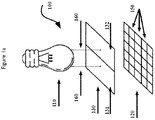
- the light source 110 provides illumination for a scene to be imaged and emits partially coherent polarised light 160.
- the light may travel directly and/or indirectly (e.g. via reflection off a sample) to the optical filter 130.
- the optical filter 130 comprises a first filter element 131 and a second filter element 132 which are arranged as an array parallel to the image sensor 120.
- the first filter element 131 is configured to attenuate the transmission of a first light spectrum which comprises polarised light emitted by the light source 110.
- the second filter element 132 is configured for transmission of a second light spectrum.
- the image sensor 120 is configured to simultaneously capture light impinging on it from both the first filter element 131 and the second filter element 132.
- Each filter element of the optical filter 130 is configured for transmission of light to a subset of the imager pixels 150, and each pixel 150 receives light via a single filter element. Hence, the image sensor 120 captures the image for each mode on a different subset of the imager pixels 150.
- FIG. 5 An example embodiment based on multimodal imaging using holography and fluorescence as the imaging modalities is illustrated in Fig. 5 .
- the light source 110 emits a coherent or partially coherent polarised light 160.
- the emitted light 160 illuminates a sample 900 positioned between the light source 110 and the optical filter 130.
- a transparent or partially transparent sample 900 e.g. a biological cell, provides a suitable object for digital in-line holography, but the same basic system may be used with off-axis holography or other sample/object types, e.g. large molecules, biological tissues etc.
- the multimodal imaging system 100 is suitable for implementation as a lens-free solution as illustrated in Fig. 5 , but standard optical components 200 (such as lenses, prisms, mirrors, apertures etc.) may also be incorporated between the light source, object and the image sensor 120 as illustrated in Fig. 7 and Fig. 8 .
- the first light spectrum comprises the emitted light 160, even when it only contains light which has been diffracted by the sample 900.
- the first filter element 131 receives the first light spectrum comprising the emitted light 160 and forming the diffraction pattern. The first filter element 131 allows transmission of the first light spectrum, but in so doing, attenuates the light thereby reducing its intensity.
- the primary mechanism employed for this attenuation is based on polarisation selectivity of the first filter element 131.
- the light forming the diffraction pattern then impinges on the image sensor 120, arriving only at the pixels 150 served by the first filter element 131.
- the second filter element 132 also receives the first light spectrum, but blocks its transmission based on spectral selectivity, high polarisation selectivity, or both. Consequently, pixel elements served by the second filter element 132 do not receive the first light spectrum.
- the sample 900 also comprises a fluorescent marker. Multiple fluorescent markers may also be used, but in this example only one will be used for simplicity of explanation.
- the light 160 impinges on the sample 900 it excites the fluorescent marker to emit light which comprises the second light spectrum.
- the second light spectrum differs from the first light spectrum.
- the first light spectrum and the second light spectrum have no common frequency components due to the wavelength shift between the excitation light (first light spectrum) and the resultant fluorescent light (second light spectrum). This is not a necessary requirement, but is helpful for explanation of this simple embodiment.
- the wavelength of the first light spectrum is shorter than the wavelength of the second light spectrum as is most often the case with fluorescence.
- the second light spectrum also has a different degree of polarisation (DOP) than the first light spectrum as is usually the case with fluorescence because it is normally unpolarised.
- DOP degree of polarisation
- the first light spectrum has a high DOP as it is polarised or at least partially polarised light, there is not a fixed range applicable, but the higher the DOP of the first light spectrum, the more controllable the light attenuation will be.
- the second light spectrum comprises fluorescent light in this example which is unpolarised light and has a DOP of 0% or thereabouts.
- Both the first light spectrum and the second light spectrum would then travel to the optical filter 130.
- the first light spectrum comprising the emitted light 160 and the diffracted light reaches the second filter element 132 it would be blocked by a spectral filter component because the spectrum of the emitted light 160 does not fall within its pass-band.
- the second filter element 132 is configured for transmission of the second light spectrum and would allow it to pass because it does fall within the pass-band of the spectral filter component. Consequently, the imager pixels 150 served by the second filter element 132 would receive the second light spectrum.
- This disparity between light intensities of the different imaging modes is particularly problematic when trying to capture the images simultaneously on different pixels 150 of the same image sensor 120.
- these approaches are not suitable for simultaneous multimodal imaging when using a single image sensor 120.
- the approach being adopted in this embodiment is to attenuate the passage of light associated with the higher intensity imaging mode so as to arrive at comparable light intensities for each of the imaging modes arriving at the imaging sensor 120.
- the same technique of attenuating the passage of light can be applied to both the first light spectrum and the second light spectrum if desired to further facilitate balancing their respective light intensities as may be required.
- the primary mechanism employed in this embodiment to attenuate the first light spectrum is based on the use of polarising filters.
- the emitted light 160, and hence the first light spectrum is linearly polarised, but other polarisation geometries may also be used.
- the first filter element 131 comprises a polarising filter component it can discriminate light based on polarity, and can also attenuate the passage of polarised light.
- the attenuation of light can be controlled by designing the Polarisation Extinction Ratio (PER) of the filter to match the desired attenuation and polarity of the first light spectrum.
- PER Polarisation Extinction Ratio
- a wire grid polarisation filter is employed, but other polarisation filter techniques known in the art may also be used.
- Fig. 4 illustrates a subset of suitable wire grid polarising filter implementations.
- the polarising filter may be designed with a wire grid orientation matching the polarity (polarisation angle) of the first light spectrum. By increasing the number or thickness, or both, of the wires, the PER of the filter is increased, i.e. attenuation of the polarised light is increased. Additionally, or alternatively, the geometric orientation of the wire grid with respect to the polarity of the polarised light may be misaligned to alter attenuation. When the polarity of linearly polarised light is orthogonal to the wire grid, attenuation is at its minimum, and when aligned with the wire grid, then attenuation is at its maximum.
- the second filter element 132 may also comprise a polarising filter component. In the current embodiment this could be used in addition to the spectral filter component to block the second light spectrum.
- the light source 110 may comprise a laser based light source, Light Emitting Diode (LED), incandescent bulb, natural light source or other means for emitting electromagnetic radiation as known in the art.
- the light source 110 may optionally comprise planar light circuits and/or photonic integrated circuits based on waveguide components to guide and manipulate light on an optical substrate. These photonic components may contain input-coupling and output-coupling structures to interface an external light source of arbitrary nature, and emit light towards an object or scene. The emitted light may be within the visible spectrum, but is equally applicable to non-visible spectra which imaging sensors may capture.
- the light source 110 may optionally comprise fibre components such as single-mode-fibre or multi-mode-fibre or light guides. Such fibre components may contain additional fibre components to control the degree of polarisation, spectrum and coherence of the light.
- spatial filters such as a pinhole provide a partially coherence light source 110.
- optical filters can be used to control the spectral content of the first light spectrum.
- the light source 110 may optionally comprise optical elements such as lenses, mirrors, beam splitters, prisms etc. to achieve illumination specifications such as beam shape, ray angularity and uniformity etc.
- the light source 110 may emit light continuously during imaging operations, i.e. the emitted light intensity remains constant or substantially constant over time.
- the light source 110 emits a pulsed light, wherein light is emitted for limited periods during imaging operations, each emission period being followed by a dormant period during which no light, or a significantly reduced light intensity is emitted.
- the pulsed operation can repeat more than once during the imaging process.
- the light source 110 is driven by an electronic circuit which is optionally in communication with the image sensor 120 for synchronization purposes.
- Filter elements 130 may be sensitive to the degree of polarisation and the spectrum of the light. At least one of the filter elements can reflect, absorb and transmit the light according to the polarisation property of the light impinging upon.
- Polarisation filters have a property known as Polarisation Extinction Ratio (PER) defined as the ratio of optical powers transmitted in the two orthogonal polarisation directions.
- PER Polarisation Extinction Ratio
- the PER value of a filter is intrinsic to the design of the filter. In an example of a wire-grid based polarisation selective filter, the wire-grid material and geometry determines the PER value. Higher PER values of a filter indicates the filter has transmittance properties highly selective to the polarisation state of the light, and vice versa. Filters with higher PER can block the polarised light from being transmitted through it to a greater extent than filters with lower PER.
- At least one of the filter elements 130 can reflect, absorb and transmit the light according to the spectral property of the light impinging upon.
- the spectral filters have the property of transmitting light with wavelength within its "pass-band” while blocking light with wavelength outside of its pass-band via absorbing or reflecting it.
- the pass-band is defined as a spectral band in which the light can be transmitted with higher efficiency than the light outside of this spectral band.
- the pass-band can be defined using parameters such as central wavelength, bandwidth, peak transmission, blocking ratio etc.
- Such wavelength selective filters can be designed as thin films of materials with different refractive indices, thin films of materials with birefringent properties, thin films of materials with absorbance. The relative thickness and combination of materials determine the pass-band parameters of such filters.
- Filter elements 130 can be manufactured in different size ranging from nanometre to metre scale.
- Patterning of the filters can be done with top-down conventional semiconductor processes or bottom-up self-assembly methods.
- the patterning allows to multiplex filters with different spectral and polarisation properties.
- Such filters can be positioned next to each other in the same plane orthogonal to light propagation direction and also in the plane along the light propagation direction.
- Image sensors 120 are composed of a plurality of light sensitive elements, usually referred to as pixels 150. Each pixel detects photons and converts them into electrons for digital processing of the optical signal.
- the operating parameters of image sensors vary significantly depending on the materials of their construction and manufacturing technology employed. They can be sensitive to a wide range of spectra, e.g. wavelength ranges of 200nm to 15 ⁇ m, and are able to operate with polarised light over the whole range of Degrees of Polarisation (DOP) from 0% to 100%.
- DOP Degrees of Polarisation
- the optical filter elements 131 & 132 can be patterned according to pixel 150 geometry of the image sensor 120. Pixels 150 and filter elements 131 & 132 can be geometrically aligned to each other such that each pixel 150 accepts light from a single filter element 131 or 132.
- pixels 150 comprising the image sensor 120 can be grouped according to the filter elements such that a subgroup of pixels 150 can collect light transmitted by a specific filter element. In the simplest case half the pixels 150 comprising the image sensor 120 receive light transmitted by the first filter element 131 and half the pixel elements receive light transmitted by the second filter element 132. However, any proportions of pixels 150 to filter element 131 or 132 may be employed and any size of image sensor 120. It can also be advantageous in some circumstances to use only a subset of the pixels 150 available on image sensor 120, e.g. so that some may be used for other purposes such as monitoring ambient light levels.
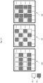
- the pixel 150 groupings may be contiguous or non-contiguous and multiple optical filter elements 131 & 132 can be arranged in arbitrary patterns, or repetitive patterns as may be appropriate for the application. A limited number of example filter arrangements are shown in Fig. 2 . Clearly, additional optical filter elements may be employed for additional imaging modalities using the same image sensor 120.
- data retrieved from image pixels 150 can be used to generate multiple images of a scene or a composite image of a scene, or to extract information about the scene, e.g. functional and morphological information. This information may be extracted by a computer, wherein it may be used to determine characteristics of the scene being imaged to effect a decision and/or process.
- Pixels 150 in the image sensor 120 must receive light intensity (energy flux) levels of light being transmitted by the filter elements 131 & 132 which is within the dynamic range of the pixels 150 in order to perform simultaneous read-out.
- the dynamic range of available image sensors varies, but is limited to a range (usually expressed in dB) depending on the image sensor technology. Therefore, for image sensors to be useful in multi-modal imaging the different modalities are required to output light intensity levels within the dynamic range of the image sensor 120. In practice, the requirement is much more stringent because most imaging modalities require at least an order of magnitude larger signal to noise ratio than 1.0. Hence, it is important to equalise light intensity levels (energy flux) impinging on the imager for different modalities to facilitate effective image capture in most circumstances.
- the intensity of light (energy flux) impinging on the image sensor 120 for the first light spectrum and the second light spectrum can be equalized through attenuation of the light resulting from at least one of the imaging modalities.
- the filter elements 131 & 132 establish this optical power balance between different imaging modalities on an image sensor 120 through taking advantage of the polarisation and spectral attributes of the light output from different modalities.
- Fig. 3 illustrates an example breakdown and schematic cross-sections of the filter elements 131 & 132 in terms of their stacked structure.
- the first element 131 consists of two filter components (stacked structures).
- the first filter component (top stack) (133) is a spectral filter component designed to transmit the pass-band corresponding to the first light spectrum and reflect the second light spectrum.
- the second light spectrum may correspond to the Stokes or Anti-stokes shifted light originated from an object in response to absorption of the light emitted from a light source 110.
- it may relate to non-resonant scattering of light emitted from a light source 110 or spontaneously emitted (blackbody) radiation. Any combination of these embodiment may be adopted to address application needs.
- the second filter component (bottom stack) 135 is a polarising filter component designed to attenuate polarised light of the first light spectrum which has been transmitted by the first filter component (top stack) 133.
- the attenuation of polarised light is an important feature of this second filter component (bottom stack) 135. It is required that the light intensity of the first light spectrum after transmission through the first filter element 131 is reduced to a level comparable with the second light spectrum after transmission through the second filter element 132 so that light impinging on the image sensor 120 falls within the dynamic range of the image sensor 120.
- the first filter element 131 attenuates the transmission of the first light spectrum while blocking transmission of the second light spectrum.
- the second filter element 132 comprises at least one filter component, in which case the filter component may be a spectral filter component or a polarising filter component. In embodiments where the second filter element 132 comprises two filter components arranged in the same light path (e.g. two stacked structures).
- the first filter component (top stack) 134 is a spectral filter component designed to transmit the pass-band corresponding to the second light spectrum.
- the first filter component also blocks transmission of the first light spectrum, but may partially transmit it, e.g. significantly attenuate it. This may, for example, be due to filter design, filter methodology, or circumstances where the first light spectrum and the second light spectrum have some immediately adjacent or common frequency components, e.g. some overlap in the frequency domain.
- the second filter component (bottom stack) 136 is a polarisation filter component differently designed from the polarising filter component 135 of the first filter element 131. It is designed to completely extinguish the linearly polarised first light spectrum but will also cause partial attenuation of the second light spectrum. In some application, e.g. fluorescence imaging, this is seen in the art as undesirable because of the low light intensity levels involved. However, it has been found that the advantages of balancing light levels impinging on the image sensor 120 for the different imaging modes can outweigh this minor disadvantage.
- the second light spectrum may comprise partially polarised light originating from the scene being imaged. The extent of attenuation of the second light spectrum depends on its degree of polarisation.
- the second filter element 132 comprises a spectral filter component and polarising filter component
- the second filter element 132 also attenuates the second light spectrum while blocking the first light spectrum.
- Fabry-Perrot filters are used to realize the spectral filter components of the two filter elements 133 and 134, but other interference filters, or other filter types (e.g. dichroic filters) may be used.
- design of Fabry-Perot filters comprises, an optically transparent cavity layer embedded between two partially reflective layers. The pass-band attributes of the spectral filter components of the first filter element 131 and the second filter element 132 can be tailored for the spectrally different light of the first light spectrum and the second light spectrum to separate the two light spectra as indicated above.
- wire-grid polarising filters are used to realise the polarising filter component of the filter elements 135 and 136.
- the wire-grid filters may comprise many parallel metallic wires that are placed in an optically transparent medium with a defined orientation, periodicity and thickness.
- a difference between the polarising filter components 135 & 136 of the first filter element 131 and the second filter element 132 is that the second polarising filter component 136 provides a higher polarised light extinction than the first polarising filter component 135. This provides the advantage that only the second light spectrum impinges on pixels 150 associated with the second filter element 132
- different levels of polarised light extinction can be achieved by using polarising filter components 135 & 136 with different Polarisation Extinction Ratios (PER). This can be achieved by using different materials for wires and surrounding medium of the wires, different geometry of the wires or wire repetition period as illustrated in Fig. 4 .
- PER Polarisation Extinction Ratios
- different levels of polarised light extinction can be achieved through changing the wire orientation with respect to polarisation angle of the polarised light 111 on the plane perpendicular to the light propagation as illustrated in Fig. 4 .
Landscapes
- Physics & Mathematics (AREA)
- Engineering & Computer Science (AREA)
- General Physics & Mathematics (AREA)
- Chemical & Material Sciences (AREA)
- Analytical Chemistry (AREA)
- General Health & Medical Sciences (AREA)
- Health & Medical Sciences (AREA)
- Spectroscopy & Molecular Physics (AREA)
- Biochemistry (AREA)
- Multimedia (AREA)
- Immunology (AREA)
- Pathology (AREA)
- Life Sciences & Earth Sciences (AREA)
- Optics & Photonics (AREA)
- Signal Processing (AREA)
- Medical Informatics (AREA)
- Radiology & Medical Imaging (AREA)
- Quality & Reliability (AREA)
- Computer Vision & Pattern Recognition (AREA)
- Theoretical Computer Science (AREA)
- Nuclear Medicine, Radiotherapy & Molecular Imaging (AREA)
- Investigating, Analyzing Materials By Fluorescence Or Luminescence (AREA)
Abstract
Description
- The present inventive concept relates to a system for the simultaneous capture of multiple images of different modalities.
- Different imaging modalities often require specialized imaging systems as the light illumination and detection parameters can vary significantly between them. These variations often lead to the use of single mode imaging systems and limit multi-modal imaging to a small subset of the available imaging options. The present concept aims to address these issues.
- In many biological and medical applications such as cell biology, histology, cytometry and oncology, the investigation of biological material can benefit from the use of multiple imaging modalities. The use of multiple modalities can help to provide information on morphology, function and composition in a manner which offers improved detail over any single technique alone.
-
US20160041094A1 discloses a lens-free imaging system suitable for in-vitro medical diagnostics with an emphasis on the detection of particles, e.g. blood cells. The approach they disclose includes imaging of a fluidic chamber either while fluid containing the particles is static or while it is flowing. With this approach they indicate that either shadow images or fluorescence images may be produced. - It is possible to capture images asynchronously and then compare or combine them later. However, it can be difficult to align the images or compare on a true like for like basis when capturing images at different times, e.g. if imaging particles suspended in a flowing fluid medium. Hence, the simultaneous capture of different imaging modalities offers an improvement in the usefulness of the resultant images. If these images are captured both simultaneously and individually, the advantage is further emphasised because the images may then be compared on a true like for like basis, or later combined electronically, or both. However, the incompatibility of different imaging modes makes simultaneous image capture challenging and often leads to the use of separate optical imaging systems which can be costly and difficult to implement in a single apparatus.
- An objective of the present inventive concept is to provide a multimodal imaging system which can capture different imaging modalities both simultaneously and individually.
- In an example embodiment the multimodal imaging system comprises a light source, an image sensor comprising a plurality of pixels, and an optical filter comprising a first filter element and a second filter element, characterised in that the light source emits partially coherent polarised light, and the first filter element and second filter element are arranged as an array parallel to the image sensor, wherein the first filter element is configured for attenuated transmission of a first light spectrum which comprises polarised light emitted by the light source, and the second filter element is configured for transmission of a second light spectrum, and the image sensor is configured to simultaneously capture light impinging on it from both the first filter element and the second filter element, wherein each filter element of the optical filter is configured for transmission of light to a subset of the imager pixels, and each pixel receives light via a single filter element.
- It is advantageous that a first light source emits light which is at least partially polarised because it provides a light spectrum suitable for selective detection based upon its polarisation. A variety of alternative embodiments are possible in accordance with this approach, e.g. the polarisation may be linear, circular, elliptical, or any other geometrical orientation or combination known in the art which generates a distinctive polarisation feature on which to base detection of the light spectrum. The second light spectrum may be unpolarised, or may be of a different polarisation or polarisation combination to the first light spectrum such that each light spectrum can be differentiated.
- In an alternative embodiment which may be combined with previously presented embodiments, the degree of polarisation of the first light spectrum is not equal to the degree of polarisation of the second light spectrum, where the degree of polarisation (DOP) is the proportion of the light which is polarised. This approach has the advantage of providing easily separable light intensity within the polarisation domain.
- In another alternative embodiment, which may be combined with any previously presented embodiments, the frequency components of light comprising the first light spectrum differ from the frequency components of light comprising the second light spectrum. This is advantageous in that the two light spectra may be separable by frequency domain criteria known in the art. While the first light spectrum and the second light spectrum are not identical, they may have some common frequency components while still being amenable to separation in the frequency domain, e.g. by low pass, high pass, band pass or band stop filtering techniques and combinations thereof. These spectral filtering techniques may be applied in ways known in the art, e.g. interference, absorptive or dichroic filters, and using implementations based on standard techniques such as multi-layer thin films.
- In another alternative embodiment, which may be combined with any previously presented embodiments, the light source may emit a pulsed light. When pulsed light is employed the first light spectrum comprises a first pulse sequence and the second light spectrum comprises a second pulse sequence. The second pulse sequence may also comprise a single pulse, i.e. a continuous, or substantially continuous energy flux level Provided the first pulse sequence and the second pulse sequence are different, this approach has the advantage of providing easily separable light intensity within the time domain.
- According to a further embodiment, which may be combined with any previously presented embodiments, the energy flux of light impinging on the image sensor from any filter element of the optical filter is within the dynamic range of the image sensor. This is particularly advantageous because different imaging modalities often result in different light intensities. Where these intensities vary significantly, the illuminance of light impinging on the image sensor exceeds the dynamic range of the sensor and thereby prevents the sensor from capturing the required image detail for all of the imaging modalities.
- In an alternative embodiment which may be combined with any previously presented embodiments, at least the first filter element comprises a spectral filter component and a polarising filter component arranged in the same light path. It is advantageous to be able to utilise the polarising filter in combination with a polarising light source as a control and selection mechanism for light passing through the filter. When combined with a spectral filter it provides an additional separation and control mechanism.
- In an alternative embodiment, the second filter element also comprises a polarising filter component, and the polarising filter component of the first filter element has a lower Polarisation Extinction Ratio (PER) than the polarising filter component of the second filter element. An advantage of this approach is that the polarising filters may be used to attenuate the passage of light which is especially advantageous when each filter is associated with a different imaging modality and the resultant light intensities of each modality vary significantly. However, the ability to use polarising filters to control attenuation is not dependent on its combination with other filter components, or on other filter elements also comprising polarising filter components .
- When polarising filters are used, an advantageous embodiment of the polarising filter component comprises a wire-grid based polarising filter. This approach to the creation of polarising filters is easy to implement and can be achieved reliably and repeatably. It also provides means of fabrication which is compatible with image sensors .
- In another alternative embodiment which may be combined with any of the other embodiments, one of the imaging modes is holographic imaging. Digital holographic imaging offers both lateral and depth resolution resulting in 3-dimensional imaging with the ability to provide detail to the micron range which is advantageous for biological and microbiological application. The detailed structural information contained in holographic images can be especially helpful in the investigation of biological materials at the microscopic level.
- In an alternative embodiment which may be combined with any of the other embodiments, one of the imaging modes is fluorescence imaging. This imaging mode is widely used in biological applications, especially in fluorescence microscopy where it is used for many applications associated with the observation of living cells and organisms. It may, for example, be used to improve the differentiation of individual cells or identify specific features of cell types. Fluorescence is also difficult to combine with other imaging modalities because it provides much lower light emission characteristics than most.
- In an alternative embodiment which may be combined with any of the other embodiments, one of the imaging modes is photoluminescence imaging. This imaging mode is widely used in industrial applications, especially in microscopy where it is used for many applications associated with the observation of defects and functions of engineered materials such as semiconductor devices in combination with an external light stimuli. It may, for example, be used to localise faults in large areas during the processing of engineered materials for failure analysis and yield improvement purposes. Photoluminescence imaging is also difficult to combine with other imaging modalities because it provides much lower light emission characteristics than most. Embodiments may combine the above, or other imaging modalities at the microscopic or macroscopic scale. This is especially advantageous wherever disparities occur between light intensity (energy flux) levels of the resultant light spectra of the imaging modes. e.g. conventional photographic imaging and phosphorescence or photoluminescence. In another alternative embodiment, the multimodal imaging system comprises Raman imaging as one of the imaging modes.
- In an additional embodiment suitable for combining with any of the previous embodiments, the multimodal imaging system is a lens-free multimodal imaging system. This is especially advantageous for microscopic applications. Conventional microscopes are bulky, expensive and difficult to scale. Lens-free microscopy offers a solution to these limitations because it is a simple and cost-effective alternative which can be implemented in a small form factor.
- The multimodal imaging system according to example embodiments of the present disclosure may be used in a method which is advantageous and alleviates problems associated with the prior art, e.g. an example method attenuates at least one light source impinging on the image sensor thereby providing that the energy flux of light impinging on the image sensor from each source, or any filter element of the optical filter, is within the dynamic range of the image sensor. Advantageously, this allows for multiple high quality images from different imaging modalities to be captured simultaneously when multiple light sources impinge on different regions of an image sensor. It is also advantageous to be able to adjust or limit the range of energy flux in some embodiments to enable lower performance and lower cost imaging sensors to be used for advanced multimodal imaging application.
- The signal intensity levels may differ significantly between different imaging modes. This difference is often found to be at least an order of magnitude, with some modality mixes resulting in much greater disparity between the light intensities of different modes. In one example embodiment, the device may be applied to a method of multimodal imaging involving holography and fluorescent imaging in which case signal intensity levels may vary by five to seven orders of magnitude.
- Image sensors commonly available on the market do not have sufficient dynamic range to be able to cater for such a large variation in intensity of impinging light sources. They can work effectively only with a limited dynamic range of received energy flux, generally measured in decibels (dB). Standard CMOS image sensors only have a dynamic range of approximately 60dB, higher end image sensors may have 70dB or more, some high end image sensors have a dynamic range of over 80dB, but very few image sensors have a dynamic range much above 93dB. Consequently, it is an objective of the current invention to maintain the energy flux of light impinging on the image sensor from all imaging modes to be within the dynamic range of the image sensor. Hence, the maximum disparity between energy flux of the simultaneous imaging modes of any embodiments should preferably meet this criteria, and preferably be less than 65dB, or more preferably be less than 75 dB, or more preferably be less than 85 dB, or more preferably be less than 95 dB or more preferably still be less than 105 dB. For some applications it may be advantageous to maintain this energy flux between any of these values, e.g. at least 10dB, or 20 dB and less that 65dB, or any other combination of the above noted values.
- An example multimodal imaging method comprises the steps of: a) illuminating a sample with a partially coherent polarised light comprising a first light spectrum and generating a second light spectrum, b) transmitting the first light spectrum and the second light spectrum through an optical filter comprising a first filter element and a second filter element arranged as an array parallel to an image sensor comprising a plurality of pixels, wherein the first light spectrum in transmitted and attenuated by the first filter element and the second light spectrum is transmitted by the second filter element, c) simultaneously capturing light transmitted by the first filter element with a first subset of imager pixels, and light transmitted by the second filter element with a second subset of imager pixels, wherein each pixel receives light via a single filter element.
- In some example embodiments, the sample may preferably be a biological sample, such as but not limited to cells, tissue, blood, or microorganisms. In another example embodiment, the sample may be a particle of biological, organic or inorganic nature. In some example embodiments, the sample may be transparent or partially transparent which is advantageous for in-line holography. In preferred example embodiments, the sample when excited by a first light spectrum, emits a second light spectrum.
- The second light spectrum is preferably generated by the process of fluorescence, but may also preferably be provided by other processes known in the art such as luminescence, phosphorescence, photoluminescence or Raman scattering, hence the second light spectrum preferably comprises light resulting from these processes.
- These processes are advantageous for the identification of features associated with a sample, and different processes provide for different imaging modalities. Example embodiments may use one or a plurality of modalities supported by one or a plurality of these processes, e.g. an example embodiment uses two different fluorescent markers for identifying different features in a sample, another example embodiment uses Raman scattering and fluorescence. Any practical combination of these processes may be used by the method.
- In some example embodiments, the frequency components of the first light spectrum differ from the frequency components of the second light spectrum. This advantageously allows for filtering and separation of the light spectra based on techniques known in the art, e.g. high pass, low pass, band pass filtering etc.
- In some example embodiments, the multimodal imaging method may additionally comprise the steps of, reading data from the first subset of imager pixels of the image sensor where light transmitted by the first filter element is captured to create a first image, and reading data from the second subset of imager pixels of the image sensor where light transmitted by the second filter element is captured to create a second image. This is advantageous for capturing multiple imaging modalities simultaneously which also allows for multiple modalities to be compared for the same image scene. Hence, information presented about the sample is greatly improved over separate consideration of the modalities where the scene may change. Additionally, the images may be combined into a single image with little additional processing, thereby offering a true multimodal image of the same scene which offers further information about the sample.
- The above, as well as additional objects, features and advantages of the present inventive concept, will be better understood through the following illustrative and nonlimiting detailed description, with reference to the appended drawings. In the drawings like reference numerals will be used for like elements unless stated otherwise.
-
Fig. 1a illustrates a basic arrangement of the multimodal imaging system. -
Fig. 1b illustrates an alternate arrangement of the multimodal imaging system. -
Fig. 2 illustration of various filter element arrangements. -
Fig. 3 illustration of filter element component arrangements. -
Fig. 4 illustration of the polarising filter component features. -
Fig. 5 illustration of a multimodal imaging system using in-line holography and fluorescence. -
Fig. 6 illustration of a multimodal imaging system using off-axis holography and fluorescence. -
Fig. 7 illustration of a multimodal lens based imaging system in transmission mode. -
Fig. 8 illustration of a multimodal lens based imaging system in reflection (epi) mode. - Referring now to
Fig. 1a which illustrates the basic arrangement of themultimodal imaging system 100. Thelight source 110 provides illumination for a scene to be imaged and emits partially coherent polarisedlight 160. The light may travel directly and/or indirectly (e.g. via reflection off a sample) to theoptical filter 130. Theoptical filter 130 comprises afirst filter element 131 and asecond filter element 132 which are arranged as an array parallel to theimage sensor 120. Thefirst filter element 131 is configured to attenuate the transmission of a first light spectrum which comprises polarised light emitted by thelight source 110. Thesecond filter element 132 is configured for transmission of a second light spectrum. Theimage sensor 120 is configured to simultaneously capture light impinging on it from both thefirst filter element 131 and thesecond filter element 132. Each filter element of theoptical filter 130 is configured for transmission of light to a subset of theimager pixels 150, and eachpixel 150 receives light via a single filter element. Hence, theimage sensor 120 captures the image for each mode on a different subset of theimager pixels 150. - An example embodiment based on multimodal imaging using holography and fluorescence as the imaging modalities is illustrated in
Fig. 5 . In this embodiment thelight source 110 emits a coherent or partially coherent polarisedlight 160. The emittedlight 160 illuminates asample 900 positioned between thelight source 110 and theoptical filter 130. A transparent or partiallytransparent sample 900, e.g. a biological cell, provides a suitable object for digital in-line holography, but the same basic system may be used with off-axis holography or other sample/object types, e.g. large molecules, biological tissues etc. Themultimodal imaging system 100 is suitable for implementation as a lens-free solution as illustrated inFig. 5 , but standard optical components 200 (such as lenses, prisms, mirrors, apertures etc.) may also be incorporated between the light source, object and theimage sensor 120 as illustrated inFig. 7 andFig. 8 . - Some of the emitted light 160 travels direct to the
optical filter 130, while emitted light 160 impinging on thetransparent sample 900 is diffracted as it passes through thesample 900. Although diffraction clearly has a significant effect on the passage of light, for samples known in the art to be suitable for in-line holographic imaging the spectrum remains substantially unchanged without any significant changes to frequency content or polarity. Hence, the first light spectrum comprises the emittedlight 160, even when it only contains light which has been diffracted by thesample 900. Thefirst filter element 131 receives the first light spectrum comprising the emittedlight 160 and forming the diffraction pattern. Thefirst filter element 131 allows transmission of the first light spectrum, but in so doing, attenuates the light thereby reducing its intensity. In an embodiment, the primary mechanism employed for this attenuation is based on polarisation selectivity of thefirst filter element 131. The light forming the diffraction pattern then impinges on theimage sensor 120, arriving only at thepixels 150 served by thefirst filter element 131. Thesecond filter element 132 also receives the first light spectrum, but blocks its transmission based on spectral selectivity, high polarisation selectivity, or both. Consequently, pixel elements served by thesecond filter element 132 do not receive the first light spectrum. - In the example embodiment of
Fig. 5 , thesample 900 also comprises a fluorescent marker. Multiple fluorescent markers may also be used, but in this example only one will be used for simplicity of explanation. When the light 160 impinges on thesample 900 it excites the fluorescent marker to emit light which comprises the second light spectrum. The second light spectrum differs from the first light spectrum. In this example embodiment the first light spectrum and the second light spectrum have no common frequency components due to the wavelength shift between the excitation light (first light spectrum) and the resultant fluorescent light (second light spectrum). This is not a necessary requirement, but is helpful for explanation of this simple embodiment. In this embodiment, the wavelength of the first light spectrum is shorter than the wavelength of the second light spectrum as is most often the case with fluorescence. In this example embodiment, the second light spectrum also has a different degree of polarisation (DOP) than the first light spectrum as is usually the case with fluorescence because it is normally unpolarised. Here the first light spectrum has a high DOP as it is polarised or at least partially polarised light, there is not a fixed range applicable, but the higher the DOP of the first light spectrum, the more controllable the light attenuation will be. The second light spectrum comprises fluorescent light in this example which is unpolarised light and has a DOP of 0% or thereabouts. - Both the first light spectrum and the second light spectrum would then travel to the
optical filter 130. When the first light spectrum comprising the emittedlight 160 and the diffracted light reaches thesecond filter element 132 it would be blocked by a spectral filter component because the spectrum of the emittedlight 160 does not fall within its pass-band. However, thesecond filter element 132 is configured for transmission of the second light spectrum and would allow it to pass because it does fall within the pass-band of the spectral filter component. Consequently, theimager pixels 150 served by thesecond filter element 132 would receive the second light spectrum. - In practice, there is a significant disparity between light intensities of the emitted light 160 which excites the fluorescent markers, and the resultant fluorescent light. This disparity can be several orders of magnitude and applies not only to the emitted light 160 but also to the diffraction pattern associated with in-line or off-axis holography. Consequently, in this example the first light spectrum has much greater light intensity than the second light spectrum.
- Simply separating the light spectra of the imaging modes according to frequency, or some other basic criteria, does not necessarily result in a working system when attempting to use a
single image sensor 120. Separation of light spectra is well known in the art and can be addressed in multiple ways which can be applied to this example embodiment in order to achieve clear separation of the first light spectrum and the second light spectrum so as to ensure they reachdifferent pixels 150, or pixel groups. However, the dynamic range ofimage sensors 120 do not allow such a significant disparity of light intensity (also known as energy flux) as is found in this example between the first light spectrum and the second light spectrum. Even for imaging modes with less significant disparities between them, it is advantageous to have closely matched energy flux levels for the first light spectrum and the second light spectrum when using thesame image sensor 120 to capture their resultant images. In this way, optimal performance of the imager may be achieved. Similarly, when the imaging modes result in significantly different spectral content for the first light spectrum and the second light spectrum, controlling light intensity to match imager performance for different wavelengths is advantageous. - This disparity between light intensities of the different imaging modes is particularly problematic when trying to capture the images simultaneously on
different pixels 150 of thesame image sensor 120. When capturing images sequentially it is possible to use alternative techniques to address the problem in part, e.g. by varying exposure time between imaging modes. However, these approaches are not suitable for simultaneous multimodal imaging when using asingle image sensor 120. Instead, the approach being adopted in this embodiment is to attenuate the passage of light associated with the higher intensity imaging mode so as to arrive at comparable light intensities for each of the imaging modes arriving at theimaging sensor 120. - Clearly, the same technique of attenuating the passage of light can be applied to both the first light spectrum and the second light spectrum if desired to further facilitate balancing their respective light intensities as may be required.
- The primary mechanism employed in this embodiment to attenuate the first light spectrum is based on the use of polarising filters. In this embodiment it will be assumed that the emitted
light 160, and hence the first light spectrum is linearly polarised, but other polarisation geometries may also be used. When thefirst filter element 131 comprises a polarising filter component it can discriminate light based on polarity, and can also attenuate the passage of polarised light. The attenuation of light can be controlled by designing the Polarisation Extinction Ratio (PER) of the filter to match the desired attenuation and polarity of the first light spectrum. - In this embodiment, a wire grid polarisation filter is employed, but other polarisation filter techniques known in the art may also be used.
Fig. 4 illustrates a subset of suitable wire grid polarising filter implementations. The polarising filter may be designed with a wire grid orientation matching the polarity (polarisation angle) of the first light spectrum. By increasing the number or thickness, or both, of the wires, the PER of the filter is increased, i.e. attenuation of the polarised light is increased. Additionally, or alternatively, the geometric orientation of the wire grid with respect to the polarity of the polarised light may be misaligned to alter attenuation. When the polarity of linearly polarised light is orthogonal to the wire grid, attenuation is at its minimum, and when aligned with the wire grid, then attenuation is at its maximum. - The
second filter element 132 may also comprise a polarising filter component. In the current embodiment this could be used in addition to the spectral filter component to block the second light spectrum. - The
light source 110 may comprise a laser based light source, Light Emitting Diode (LED), incandescent bulb, natural light source or other means for emitting electromagnetic radiation as known in the art. Thelight source 110 may optionally comprise planar light circuits and/or photonic integrated circuits based on waveguide components to guide and manipulate light on an optical substrate. These photonic components may contain input-coupling and output-coupling structures to interface an external light source of arbitrary nature, and emit light towards an object or scene. The emitted light may be within the visible spectrum, but is equally applicable to non-visible spectra which imaging sensors may capture. - The
light source 110 may optionally comprise fibre components such as single-mode-fibre or multi-mode-fibre or light guides. Such fibre components may contain additional fibre components to control the degree of polarisation, spectrum and coherence of the light. - When an incandescent bulb, or other incoherent
light source 110 is used, spatial filters such as a pinhole provide a partially coherencelight source 110. Optionally, optical filters can be used to control the spectral content of the first light spectrum. Thelight source 110 may optionally comprise optical elements such as lenses, mirrors, beam splitters, prisms etc. to achieve illumination specifications such as beam shape, ray angularity and uniformity etc. - The
light source 110 may emit light continuously during imaging operations, i.e. the emitted light intensity remains constant or substantially constant over time. In an alternative embodiment, thelight source 110 emits a pulsed light, wherein light is emitted for limited periods during imaging operations, each emission period being followed by a dormant period during which no light, or a significantly reduced light intensity is emitted. The pulsed operation can repeat more than once during the imaging process. Thelight source 110 is driven by an electronic circuit which is optionally in communication with theimage sensor 120 for synchronization purposes. -
Filter elements 130 may be sensitive to the degree of polarisation and the spectrum of the light. At least one of the filter elements can reflect, absorb and transmit the light according to the polarisation property of the light impinging upon. Polarisation filters have a property known as Polarisation Extinction Ratio (PER) defined as the ratio of optical powers transmitted in the two orthogonal polarisation directions. The PER value of a filter is intrinsic to the design of the filter. In an example of a wire-grid based polarisation selective filter, the wire-grid material and geometry determines the PER value. Higher PER values of a filter indicates the filter has transmittance properties highly selective to the polarisation state of the light, and vice versa. Filters with higher PER can block the polarised light from being transmitted through it to a greater extent than filters with lower PER. - At least one of the
filter elements 130 can reflect, absorb and transmit the light according to the spectral property of the light impinging upon. The spectral filters have the property of transmitting light with wavelength within its "pass-band" while blocking light with wavelength outside of its pass-band via absorbing or reflecting it. The pass-band is defined as a spectral band in which the light can be transmitted with higher efficiency than the light outside of this spectral band. - The pass-band can be defined using parameters such as central wavelength, bandwidth, peak transmission, blocking ratio etc. Such wavelength selective filters can be designed as thin films of materials with different refractive indices, thin films of materials with birefringent properties, thin films of materials with absorbance. The relative thickness and combination of materials determine the pass-band parameters of such filters.
Filter elements 130 can be manufactured in different size ranging from nanometre to metre scale. - Patterning of the filters can be done with top-down conventional semiconductor processes or bottom-up self-assembly methods. The patterning allows to multiplex filters with different spectral and polarisation properties. Such filters can be positioned next to each other in the same plane orthogonal to light propagation direction and also in the plane along the light propagation direction.
-
Image sensors 120 are composed of a plurality of light sensitive elements, usually referred to aspixels 150. Each pixel detects photons and converts them into electrons for digital processing of the optical signal. The operating parameters of image sensors vary significantly depending on the materials of their construction and manufacturing technology employed. They can be sensitive to a wide range of spectra, e.g. wavelength ranges of 200nm to 15 µm, and are able to operate with polarised light over the whole range of Degrees of Polarisation (DOP) from 0% to 100%. - According to an embodiment compatible with all previously disclosed embodiments, the
optical filter elements 131 & 132 can be patterned according topixel 150 geometry of theimage sensor 120.Pixels 150 and filterelements 131 & 132 can be geometrically aligned to each other such that eachpixel 150 accepts light from asingle filter element - Alternatively,
pixels 150 comprising theimage sensor 120 can be grouped according to the filter elements such that a subgroup ofpixels 150 can collect light transmitted by a specific filter element. In the simplest case half thepixels 150 comprising theimage sensor 120 receive light transmitted by thefirst filter element 131 and half the pixel elements receive light transmitted by thesecond filter element 132. However, any proportions ofpixels 150 to filterelement image sensor 120. It can also be advantageous in some circumstances to use only a subset of thepixels 150 available onimage sensor 120, e.g. so that some may be used for other purposes such as monitoring ambient light levels. - Similarly, the
pixel 150 groupings may be contiguous or non-contiguous and multipleoptical filter elements 131 & 132 can be arranged in arbitrary patterns, or repetitive patterns as may be appropriate for the application. A limited number of example filter arrangements are shown inFig. 2 . Clearly, additional optical filter elements may be employed for additional imaging modalities using thesame image sensor 120. - After electronic read-out of the
image sensor 120, data retrieved fromimage pixels 150 can be used to generate multiple images of a scene or a composite image of a scene, or to extract information about the scene, e.g. functional and morphological information. This information may be extracted by a computer, wherein it may be used to determine characteristics of the scene being imaged to effect a decision and/or process. -
Pixels 150 in theimage sensor 120 must receive light intensity (energy flux) levels of light being transmitted by thefilter elements 131 & 132 which is within the dynamic range of thepixels 150 in order to perform simultaneous read-out. The dynamic range of available image sensors varies, but is limited to a range (usually expressed in dB) depending on the image sensor technology. Therefore, for image sensors to be useful in multi-modal imaging the different modalities are required to output light intensity levels within the dynamic range of theimage sensor 120. In practice, the requirement is much more stringent because most imaging modalities require at least an order of magnitude larger signal to noise ratio than 1.0. Hence, it is important to equalise light intensity levels (energy flux) impinging on the imager for different modalities to facilitate effective image capture in most circumstances. - According to one aspect of this inventive concept, the intensity of light (energy flux) impinging on the
image sensor 120 for the first light spectrum and the second light spectrum can be equalized through attenuation of the light resulting from at least one of the imaging modalities. Thefilter elements 131 & 132 establish this optical power balance between different imaging modalities on animage sensor 120 through taking advantage of the polarisation and spectral attributes of the light output from different modalities. -
Fig. 3 illustrates an example breakdown and schematic cross-sections of thefilter elements 131 & 132 in terms of their stacked structure. Thefirst element 131 consists of two filter components (stacked structures). The first filter component (top stack) (133) is a spectral filter component designed to transmit the pass-band corresponding to the first light spectrum and reflect the second light spectrum. In various embodiments the second light spectrum may correspond to the Stokes or Anti-stokes shifted light originated from an object in response to absorption of the light emitted from alight source 110. In alternative embodiments it may relate to non-resonant scattering of light emitted from alight source 110 or spontaneously emitted (blackbody) radiation. Any combination of these embodiment may be adopted to address application needs. - The second filter component (bottom stack) 135 is a polarising filter component designed to attenuate polarised light of the first light spectrum which has been transmitted by the first filter component (top stack) 133. The attenuation of polarised light is an important feature of this second filter component (bottom stack) 135. It is required that the light intensity of the first light spectrum after transmission through the
first filter element 131 is reduced to a level comparable with the second light spectrum after transmission through thesecond filter element 132 so that light impinging on theimage sensor 120 falls within the dynamic range of theimage sensor 120. Thus, thefirst filter element 131 attenuates the transmission of the first light spectrum while blocking transmission of the second light spectrum. - The
second filter element 132 comprises at least one filter component, in which case the filter component may be a spectral filter component or a polarising filter component. In embodiments where thesecond filter element 132 comprises two filter components arranged in the same light path (e.g. two stacked structures). The first filter component (top stack) 134 is a spectral filter component designed to transmit the pass-band corresponding to the second light spectrum. - The first filter component also blocks transmission of the first light spectrum, but may partially transmit it, e.g. significantly attenuate it. This may, for example, be due to filter design, filter methodology, or circumstances where the first light spectrum and the second light spectrum have some immediately adjacent or common frequency components, e.g. some overlap in the frequency domain.
- The second filter component (bottom stack) 136 is a polarisation filter component differently designed from the
polarising filter component 135 of thefirst filter element 131. It is designed to completely extinguish the linearly polarised first light spectrum but will also cause partial attenuation of the second light spectrum. In some application, e.g. fluorescence imaging, this is seen in the art as undesirable because of the low light intensity levels involved. However, it has been found that the advantages of balancing light levels impinging on theimage sensor 120 for the different imaging modes can outweigh this minor disadvantage. The second light spectrum may comprise partially polarised light originating from the scene being imaged. The extent of attenuation of the second light spectrum depends on its degree of polarisation. For example, unpolarised light will be reduced by a factor of 50%, while polarised light will be reduced by a factor of 100%. Hence, in embodiments where thesecond filter element 132 comprises a spectral filter component and polarising filter component, thesecond filter element 132 also attenuates the second light spectrum while blocking the first light spectrum. - In an example embodiment, Fabry-Perrot filters are used to realize the spectral filter components of the two
filter elements first filter element 131 and thesecond filter element 132 can be tailored for the spectrally different light of the first light spectrum and the second light spectrum to separate the two light spectra as indicated above. - In an example embodiment which may be combined with any of the above embodiments, wire-grid polarising filters are used to realise the polarising filter component of the
filter elements polarising filter components 135 & 136 of thefirst filter element 131 and thesecond filter element 132 is that the secondpolarising filter component 136 provides a higher polarised light extinction than the firstpolarising filter component 135. This provides the advantage that only the second light spectrum impinges onpixels 150 associated with thesecond filter element 132 - In an example embodiment, different levels of polarised light extinction can be achieved by using polarising
filter components 135 & 136 with different Polarisation Extinction Ratios (PER). This can be achieved by using different materials for wires and surrounding medium of the wires, different geometry of the wires or wire repetition period as illustrated inFig. 4 . - In another example embodiment which may also be combined with the previous embodiment, different levels of polarised light extinction can be achieved through changing the wire orientation with respect to polarisation angle of the polarised light 111 on the plane perpendicular to the light propagation as illustrated in
Fig. 4 . - Larger angular mismatch between the wire orientation and light polarisation angles reduces the polarised light extinction. Such mechanisms can be used to achieve varying attenuation levels by the
polarising filter component 135 of thefirst filter element 131. On the other hand, it is desired to have maximum polarised light attenuation by thepolarising filter component 136 of thesecond filter element 132. This condition can be realized through using a high PER filter of which the orientation of the wire-grids are aligned with the polarisation angle of the light 111 as shown inFig. 4 .
Claims (15)
- A multimodal imaging system (100) comprising:a light source (110),an image sensor (120) comprising a plurality of pixels (150), and
an optical filter (130) comprising a first filter element (131) and a second filter element (132),characterised in that;the light source (110) emits partially coherent polarised light (160), andthe first filter element (131) and second filter element (132) are arranged as an array parallel to the image sensor (120), wherein the first filter element (131) is configured for attenuated transmission of a first light spectrum which comprises polarised light emitted by the light source (110), and the second filter element (132) is configured for transmission of a second light spectrum, andthe image sensor (120) is configured to simultaneously capture light impinging on it from both the first filter element (131) and the second filter element (132), wherein each filter element of the optical filter (130) is configured for transmission of light to a subset of the imager pixels (150), and each pixel (150) receives light via a single filter element. - A multimodal imaging system (100) according to claim 1, wherein the frequency components of the first light spectrum differ from the frequency components of the second light spectrum.
- A multimodal imaging system (100) according to any of the previous claims, wherein the degree of polarisation of the first light spectrum is not equal to the degree of polarisation of the second light spectrum.
- A multimodal imaging system (100) according to any of the previous claims, wherein the light source (110) emits a pulsed light and the first light spectrum comprises a first pulse sequence.
- A multimodal imaging system (100) according to any of the previous claims, wherein the energy flux of light impinging on the image sensor (120) from any filter element of the optical filter (130) is within the dynamic range of the image sensor (120).
- A multimodal imaging system (100) according to any of the previous claims, wherein at least the first filter element (131) comprises
a spectral filter component and a polarising filter component arranged in the same light path. - A multimodal imaging system (100) according to claim 5, wherein
the second filter element (132) also comprises a polarising filter component, and the polarising filter component of the first filter element (131) has a lower Polarisation Extinction Ratio (PER) than the polarising filter component of the second filter element (132). - A multimodal imaging system (100) according to any of the previous claims, wherein one of the imaging modes is holographic imaging.
- A multimodal imaging system (100) according to any of the previous claims, wherein one of the imaging modes is fluorescence imaging.
- A multimodal imaging system (100) according to any of the previous claims, wherein the multimodal imaging system (100) is a lens-free multimodal imaging system (100).
- An apparatus for characterising biological material comprising a multimodal imaging system according to any of the previous claims.
- A multimodal imaging method comprising the steps of:a) illuminating a sample (900) with a partially coherent polarised light (160) comprising a first light spectrum and generating a second light spectrum,b) transmitting the first light spectrum and the second light spectrum through an optical filter (130) comprising a first filter element (131) and a second filter element (132) arranged as an array parallel to an image sensor (120) comprising a plurality of pixels (150), wherein the first light spectrum in transmitted and attenuated by the first filter element (131) and the second light spectrum is transmitted by the second filter element (132),c) simultaneously capturing light transmitted by the first filter element (131) with a first subset of imager pixels (150), and light transmitted by the second filter element (132) with a second subset of imager pixels (150), wherein each pixel receives light via a single filter element.
- A multimodal imaging method according to claim 12 wherein the frequency components of the first light spectrum differ from the frequency components of the second light spectrum.
- A multimodal imaging method according to any of clams 12 and 13, wherein the energy flux of light impinging on the image sensor (120) from any filter element of the optical filter (130) is within the dynamic range of the image sensor (120).
- A multimodal imaging method according to any claims 11 to 14 wherein the method additionally comprises the steps of:d) reading data from the first subset of imager pixels (150) of the image sensor (120) where light transmitted by the first filter element (131) is captured to create a first image, ande) reading data from the second subset of imager pixels (150) of the image sensor (120) where light transmitted by the second filter element (131) is captured to create a second image.
Applications Claiming Priority (1)
| Application Number | Priority Date | Filing Date | Title |
|---|---|---|---|
| EP18212415 | 2018-12-13 |
Publications (2)
| Publication Number | Publication Date |
|---|---|
| EP3667299A1 true EP3667299A1 (en) | 2020-06-17 |
| EP3667299B1 EP3667299B1 (en) | 2022-11-09 |
Family
ID=64901850
Family Applications (1)
| Application Number | Title | Priority Date | Filing Date |
|---|---|---|---|
| EP19211603.6A Active EP3667299B1 (en) | 2018-12-13 | 2019-11-26 | Multimodal imaging system |
Country Status (2)
| Country | Link |
|---|---|
| US (1) | US11016022B2 (en) |
| EP (1) | EP3667299B1 (en) |
Cited By (3)
| Publication number | Priority date | Publication date | Assignee | Title |
|---|---|---|---|---|
| EP4145211A1 (en) * | 2021-09-02 | 2023-03-08 | Leica Microsystems CMS GmbH | Optical apparatus |
| WO2023057735A1 (en) * | 2021-10-05 | 2023-04-13 | Dmg Biophotonics Limited | Apparatus and method for multi-characteristic measurement of radiation properties |
| US12631888B2 (en) | 2021-09-02 | 2026-05-19 | Leica Microsystems Cms Gmbh | Optical apparatus |
Families Citing this family (2)
| Publication number | Priority date | Publication date | Assignee | Title |
|---|---|---|---|---|
| US12320741B2 (en) * | 2019-12-27 | 2025-06-03 | Sony Group Corporation | Polarization imaging system and polarization imaging method |
| CN114330488B (en) * | 2021-11-19 | 2025-09-12 | 浪潮(北京)电子信息产业有限公司 | Multimodal data processing method, device, equipment and storage medium |
Citations (3)
| Publication number | Priority date | Publication date | Assignee | Title |
|---|---|---|---|---|
| US20100140504A1 (en) * | 2007-04-18 | 2010-06-10 | Stephen Edwin Dominic Webb | Fluorescence measurement |
| US20120087645A1 (en) * | 2010-10-12 | 2012-04-12 | Omnivision Technologies, Inc. | Visible and infrared dual mode imaging system |
| US20160041094A1 (en) | 2014-08-08 | 2016-02-11 | Omnivision Technologies, Inc. | Lens-free imaging system and method for detecting particles in sample deposited on image sensor |
Family Cites Families (34)
| Publication number | Priority date | Publication date | Assignee | Title |
|---|---|---|---|---|
| US5751384A (en) * | 1995-05-23 | 1998-05-12 | The Board Of Regents Of The University Of Colorado | Color polarizers for polarizing an additive color spectrum along a first axis and it's compliment along a second axis |
| US20040111031A1 (en) * | 1999-07-22 | 2004-06-10 | Alfano Robert R. | Spectral polarizing tomographic dermatoscope |
| US6826424B1 (en) * | 2000-12-19 | 2004-11-30 | Haishan Zeng | Methods and apparatus for fluorescence and reflectance imaging and spectroscopy and for contemporaneous measurements of electromagnetic radiation with multiple measuring devices |
| US6570659B2 (en) * | 2001-03-16 | 2003-05-27 | Lightlab Imaging, Llc | Broadband light source system and method and light source combiner |
| US7016717B2 (en) * | 2002-07-05 | 2006-03-21 | The Regents Of The University Of California | Near-infrared spectroscopic tissue imaging for medical applications |
| EP1631788B1 (en) | 2003-05-16 | 2007-03-14 | Universite Libre De Bruxelles | Digital holographic microscope for 3d imaging and process using it |
| US7072039B2 (en) * | 2003-08-20 | 2006-07-04 | Itt Manufacturing Enterprises, Inc. | Active multiple-color imaging polarimetry |
| US8473035B2 (en) * | 2003-09-15 | 2013-06-25 | Beth Israel Deaconess Medical Center | Medical imaging systems |
| US7920908B2 (en) * | 2003-10-16 | 2011-04-05 | David Hattery | Multispectral imaging for quantitative contrast of functional and structural features of layers inside optically dense media such as tissue |
| US7530948B2 (en) * | 2005-02-28 | 2009-05-12 | University Of Washington | Tethered capsule endoscope for Barrett's Esophagus screening |
| JPWO2007026521A1 (en) | 2005-08-30 | 2009-03-26 | パイオニア株式会社 | Optical pickup device and hologram recording / reproducing system |
| US7382456B2 (en) * | 2005-12-29 | 2008-06-03 | Honeywell Asca, Inc. | Spectroscopic sensor for measuring sheet properties |
| US20080118886A1 (en) | 2006-11-21 | 2008-05-22 | Rongguang Liang | Apparatus for dental oct imaging |
| WO2010004365A1 (en) * | 2008-07-10 | 2010-01-14 | Ecole Polytechnique Federale De Lausanne (Epfl) | Functional optical coherent imaging |
| JP5572326B2 (en) * | 2009-03-26 | 2014-08-13 | オリンパス株式会社 | Image processing apparatus, imaging apparatus, image processing program, and image processing method |
| US8467858B2 (en) * | 2009-04-29 | 2013-06-18 | Tomophase Corporation | Image-guided thermotherapy based on selective tissue thermal treatment |
| US8357281B2 (en) * | 2009-09-21 | 2013-01-22 | Advanced Analytical Technologies, Inc. | Multi-wavelength fluorescence detection system for multiplexed capillary electrophoresis |
| EP3136079B1 (en) | 2009-10-20 | 2020-02-12 | The Regents of The University of California | Incoherent lensfree cell holography and microscopy on a chip |
| US20110292258A1 (en) * | 2010-05-28 | 2011-12-01 | C2Cure, Inc. | Two sensor imaging systems |
| US10126709B2 (en) | 2013-12-02 | 2018-11-13 | Imec Vzw | Apparatus and method for performing in-line lens-free digital holography of an object |
| EP3111822A4 (en) * | 2014-04-08 | 2018-05-16 | Olympus Corporation | Fluorescence endoscopy system |
| JP6065875B2 (en) * | 2014-06-02 | 2017-01-25 | 横河電機株式会社 | Polarization inspection equipment |
| US10398294B2 (en) * | 2014-07-24 | 2019-09-03 | Z Square Ltd. | Illumination sources for multicore fiber endoscopes |
| US9787916B2 (en) * | 2014-10-28 | 2017-10-10 | The Boeing Company | Active real-time characterization system |
| EP3206560B1 (en) * | 2014-12-25 | 2024-06-12 | Sony Group Corporation | Medical imaging system and illumination device |
| US10390718B2 (en) * | 2015-03-20 | 2019-08-27 | East Carolina University | Multi-spectral physiologic visualization (MSPV) using laser imaging methods and systems for blood flow and perfusion imaging and quantification in an endoscopic design |
| WO2017099253A1 (en) * | 2015-12-11 | 2017-06-15 | 株式会社ニコン | Polarization property image measurement device and polarization property image measurement method |
| WO2017196995A1 (en) | 2016-05-11 | 2017-11-16 | The Regents Of The University Of California | Method and system for pixel super-resolution of multiplexed holographic color images |
| WO2017201093A1 (en) * | 2016-05-17 | 2017-11-23 | Hypermed Imaging, Inc. | Hyperspectral imager coupled with indicator molecule tracking |
| US20190137932A1 (en) | 2016-05-25 | 2019-05-09 | The Regents Of The University Of California | Wide-field imaging of birefringent crystals and other materials using lens-free polarized microscope |
| JP6961241B2 (en) | 2016-10-11 | 2021-11-05 | 国立大学法人神戸大学 | Digital holographic microscope |
| US10394008B2 (en) * | 2016-10-19 | 2019-08-27 | Cornell University | Hyperspectral multiphoton microscope for biomedical applications |
| US10849486B2 (en) * | 2017-05-08 | 2020-12-01 | Sony Corporation | Image acquisition system, image acquisition method, control device, and control method |
| JP2022526626A (en) * | 2019-04-08 | 2022-05-25 | アクティブ サージカル, インコーポレイテッド | Systems and methods for medical imaging |
-
2019
- 2019-11-26 EP EP19211603.6A patent/EP3667299B1/en active Active
- 2019-12-13 US US16/713,549 patent/US11016022B2/en active Active
Patent Citations (3)
| Publication number | Priority date | Publication date | Assignee | Title |
|---|---|---|---|---|
| US20100140504A1 (en) * | 2007-04-18 | 2010-06-10 | Stephen Edwin Dominic Webb | Fluorescence measurement |
| US20120087645A1 (en) * | 2010-10-12 | 2012-04-12 | Omnivision Technologies, Inc. | Visible and infrared dual mode imaging system |
| US20160041094A1 (en) | 2014-08-08 | 2016-02-11 | Omnivision Technologies, Inc. | Lens-free imaging system and method for detecting particles in sample deposited on image sensor |
Non-Patent Citations (1)
| Title |
|---|
| CHOWDHURY SHWETADWIP ET AL: "Simultaneous fluorescence and phase imaging with extensions toward sub-diffraction resolution via structured-illumination(Conference Presentation)", PROGRESS IN BIOMEDICAL OPTICS AND IMAGING, SPIE - INTERNATIONAL SOCIETY FOR OPTICAL ENGINEERING, BELLINGHAM, WA, US, vol. 9713, 15 March 2016 (2016-03-15), pages 97131J - 97131J, XP060066621, ISSN: 1605-7422, ISBN: 978-1-5106-0027-0, DOI: 10.1117/12.2213044 * |
Cited By (3)
| Publication number | Priority date | Publication date | Assignee | Title |
|---|---|---|---|---|
| EP4145211A1 (en) * | 2021-09-02 | 2023-03-08 | Leica Microsystems CMS GmbH | Optical apparatus |
| US12631888B2 (en) | 2021-09-02 | 2026-05-19 | Leica Microsystems Cms Gmbh | Optical apparatus |
| WO2023057735A1 (en) * | 2021-10-05 | 2023-04-13 | Dmg Biophotonics Limited | Apparatus and method for multi-characteristic measurement of radiation properties |
Also Published As
| Publication number | Publication date |
|---|---|
| US11016022B2 (en) | 2021-05-25 |
| EP3667299B1 (en) | 2022-11-09 |
| US20200191706A1 (en) | 2020-06-18 |
Similar Documents
| Publication | Publication Date | Title |
|---|---|---|
| EP3667299B1 (en) | Multimodal imaging system | |
| KR102780276B1 (en) | Spectrometer on a chip | |
| US9343494B2 (en) | Light guided pixel configured for emissions detection and comprising a guide layer with a wavelength selective filter material and a light detector layer | |
| US9041930B1 (en) | Digital pathology system | |
| US8767216B2 (en) | Holographically illuminated imaging devices | |
| CA2996969C (en) | Mobile microscope | |
| CN110118758B (en) | Scattering fluorescence bimodal flow type imaging system | |
| CN109540853A (en) | For the defects detection of sample and the system and method for photoluminescence measurement | |
| JP2008502929A (en) | Inspection apparatus or inspection method for fine structure by reflected or transmitted infrared light | |
| US11041756B2 (en) | Method and apparatus of filtering light using a spectrometer enhanced with additional spectral filters with optical analysis of fluorescence and scattered light from particles suspended in a liquid medium using confocal and non confocal illumination and imaging | |
| US9739716B2 (en) | Method for regulating the relative position of an analyte in relation to a light beam | |
| US8633432B2 (en) | Reflective focusing and transmissive projection device | |
| CN115876789A (en) | A dark field imaging method and device | |
| US20160327433A1 (en) | Title: integrated packaging for multi-component sensors | |
| EP3227740B1 (en) | Image cytometer | |
| WO2022218329A1 (en) | Fluorescence quantitative pcr processing method and system | |
| JP2009009139A (en) | Wavelength-specific phase microscopy | |
| JP2005524069A (en) | Fluorescence detection apparatus and method having light emitting diode as excitation light source | |
| US20230288339A1 (en) | Rapid Optical Analysis System | |
| JPH10227694A (en) | Luminescence identifying apparatus | |
| US20230085045A1 (en) | Microscope for high-resolution and specific analysis of biological substances, and method of analysis | |
| Arpali et al. | Beam shaping on a fluorescent on-chip imaging system | |
| KR20250128818A (en) | Optical measuring apparatus | |
| KR20260015987A (en) | Optical measuring apparatus | |
| Khan et al. | Setting up of a total internal reflection fluorescent microscope (TIRFM) system: a detailed overview |
Legal Events
| Date | Code | Title | Description |
|---|---|---|---|
| PUAI | Public reference made under article 153(3) epc to a published international application that has entered the european phase |
Free format text: ORIGINAL CODE: 0009012 |
|
| STAA | Information on the status of an ep patent application or granted ep patent |
Free format text: STATUS: THE APPLICATION HAS BEEN PUBLISHED |
|
| AK | Designated contracting states |
Kind code of ref document: A1 Designated state(s): AL AT BE BG CH CY CZ DE DK EE ES FI FR GB GR HR HU IE IS IT LI LT LU LV MC MK MT NL NO PL PT RO RS SE SI SK SM TR |
|
| AX | Request for extension of the european patent |
Extension state: BA ME |
|
| STAA | Information on the status of an ep patent application or granted ep patent |
Free format text: STATUS: REQUEST FOR EXAMINATION WAS MADE |
|
| 17P | Request for examination filed |
Effective date: 20201210 |
|
| RBV | Designated contracting states (corrected) |
Designated state(s): AL AT BE BG CH CY CZ DE DK EE ES FI FR GB GR HR HU IE IS IT LI LT LU LV MC MK MT NL NO PL PT RO RS SE SI SK SM TR |
|
| GRAP | Despatch of communication of intention to grant a patent |
Free format text: ORIGINAL CODE: EPIDOSNIGR1 |
|
| STAA | Information on the status of an ep patent application or granted ep patent |
Free format text: STATUS: GRANT OF PATENT IS INTENDED |
|
| RIC1 | Information provided on ipc code assigned before grant |
Ipc: G01N 21/21 20060101ALI20220429BHEP Ipc: G01N 21/25 20060101ALI20220429BHEP Ipc: G01N 21/65 20060101ALI20220429BHEP Ipc: G01N 21/17 20060101ALI20220429BHEP Ipc: G01N 21/64 20060101AFI20220429BHEP |
|
| INTG | Intention to grant announced |
Effective date: 20220520 |
|
| GRAS | Grant fee paid |
Free format text: ORIGINAL CODE: EPIDOSNIGR3 |
|
| GRAA | (expected) grant |
Free format text: ORIGINAL CODE: 0009210 |
|
| STAA | Information on the status of an ep patent application or granted ep patent |
Free format text: STATUS: THE PATENT HAS BEEN GRANTED |
|
| AK | Designated contracting states |
Kind code of ref document: B1 Designated state(s): AL AT BE BG CH CY CZ DE DK EE ES FI FR GB GR HR HU IE IS IT LI LT LU LV MC MK MT NL NO PL PT RO RS SE SI SK SM TR |
|
| REG | Reference to a national code |
Ref country code: GB Ref legal event code: FG4D |
|
| REG | Reference to a national code |
Ref country code: CH Ref legal event code: EP Ref country code: AT Ref legal event code: REF Ref document number: 1530689 Country of ref document: AT Kind code of ref document: T Effective date: 20221115 |
|
| REG | Reference to a national code |
Ref country code: DE Ref legal event code: R096 Ref document number: 602019021651 Country of ref document: DE |
|
| REG | Reference to a national code |
Ref country code: IE Ref legal event code: FG4D |
|
| REG | Reference to a national code |
Ref country code: LT Ref legal event code: MG9D |
|
| REG | Reference to a national code |
Ref country code: NL Ref legal event code: MP Effective date: 20221109 |
|
| REG | Reference to a national code |
Ref country code: AT Ref legal event code: MK05 Ref document number: 1530689 Country of ref document: AT Kind code of ref document: T Effective date: 20221109 |
|
| PG25 | Lapsed in a contracting state [announced via postgrant information from national office to epo] |
Ref country code: SE Free format text: LAPSE BECAUSE OF FAILURE TO SUBMIT A TRANSLATION OF THE DESCRIPTION OR TO PAY THE FEE WITHIN THE PRESCRIBED TIME-LIMIT Effective date: 20221109 Ref country code: PT Free format text: LAPSE BECAUSE OF FAILURE TO SUBMIT A TRANSLATION OF THE DESCRIPTION OR TO PAY THE FEE WITHIN THE PRESCRIBED TIME-LIMIT Effective date: 20230309 Ref country code: NO Free format text: LAPSE BECAUSE OF FAILURE TO SUBMIT A TRANSLATION OF THE DESCRIPTION OR TO PAY THE FEE WITHIN THE PRESCRIBED TIME-LIMIT Effective date: 20230209 Ref country code: LT Free format text: LAPSE BECAUSE OF FAILURE TO SUBMIT A TRANSLATION OF THE DESCRIPTION OR TO PAY THE FEE WITHIN THE PRESCRIBED TIME-LIMIT Effective date: 20221109 Ref country code: FI Free format text: LAPSE BECAUSE OF FAILURE TO SUBMIT A TRANSLATION OF THE DESCRIPTION OR TO PAY THE FEE WITHIN THE PRESCRIBED TIME-LIMIT Effective date: 20221109 Ref country code: ES Free format text: LAPSE BECAUSE OF FAILURE TO SUBMIT A TRANSLATION OF THE DESCRIPTION OR TO PAY THE FEE WITHIN THE PRESCRIBED TIME-LIMIT Effective date: 20221109 Ref country code: AT Free format text: LAPSE BECAUSE OF FAILURE TO SUBMIT A TRANSLATION OF THE DESCRIPTION OR TO PAY THE FEE WITHIN THE PRESCRIBED TIME-LIMIT Effective date: 20221109 |
|
| PG25 | Lapsed in a contracting state [announced via postgrant information from national office to epo] |
Ref country code: RS Free format text: LAPSE BECAUSE OF FAILURE TO SUBMIT A TRANSLATION OF THE DESCRIPTION OR TO PAY THE FEE WITHIN THE PRESCRIBED TIME-LIMIT Effective date: 20221109 Ref country code: PL Free format text: LAPSE BECAUSE OF FAILURE TO SUBMIT A TRANSLATION OF THE DESCRIPTION OR TO PAY THE FEE WITHIN THE PRESCRIBED TIME-LIMIT Effective date: 20221109 Ref country code: LV Free format text: LAPSE BECAUSE OF FAILURE TO SUBMIT A TRANSLATION OF THE DESCRIPTION OR TO PAY THE FEE WITHIN THE PRESCRIBED TIME-LIMIT Effective date: 20221109 Ref country code: IS Free format text: LAPSE BECAUSE OF FAILURE TO SUBMIT A TRANSLATION OF THE DESCRIPTION OR TO PAY THE FEE WITHIN THE PRESCRIBED TIME-LIMIT Effective date: 20230309 Ref country code: HR Free format text: LAPSE BECAUSE OF FAILURE TO SUBMIT A TRANSLATION OF THE DESCRIPTION OR TO PAY THE FEE WITHIN THE PRESCRIBED TIME-LIMIT Effective date: 20221109 Ref country code: GR Free format text: LAPSE BECAUSE OF FAILURE TO SUBMIT A TRANSLATION OF THE DESCRIPTION OR TO PAY THE FEE WITHIN THE PRESCRIBED TIME-LIMIT Effective date: 20230210 |
|
| P01 | Opt-out of the competence of the unified patent court (upc) registered |
Effective date: 20230513 |
|
| PG25 | Lapsed in a contracting state [announced via postgrant information from national office to epo] |
Ref country code: NL Free format text: LAPSE BECAUSE OF FAILURE TO SUBMIT A TRANSLATION OF THE DESCRIPTION OR TO PAY THE FEE WITHIN THE PRESCRIBED TIME-LIMIT Effective date: 20221109 |
|
| REG | Reference to a national code |
Ref country code: CH Ref legal event code: PL |
|
| REG | Reference to a national code |
Ref country code: BE Ref legal event code: MM Effective date: 20221130 |
|
| PG25 | Lapsed in a contracting state [announced via postgrant information from national office to epo] |
Ref country code: SM Free format text: LAPSE BECAUSE OF FAILURE TO SUBMIT A TRANSLATION OF THE DESCRIPTION OR TO PAY THE FEE WITHIN THE PRESCRIBED TIME-LIMIT Effective date: 20221109 Ref country code: RO Free format text: LAPSE BECAUSE OF FAILURE TO SUBMIT A TRANSLATION OF THE DESCRIPTION OR TO PAY THE FEE WITHIN THE PRESCRIBED TIME-LIMIT Effective date: 20221109 Ref country code: LI Free format text: LAPSE BECAUSE OF NON-PAYMENT OF DUE FEES Effective date: 20221130 Ref country code: EE Free format text: LAPSE BECAUSE OF FAILURE TO SUBMIT A TRANSLATION OF THE DESCRIPTION OR TO PAY THE FEE WITHIN THE PRESCRIBED TIME-LIMIT Effective date: 20221109 Ref country code: DK Free format text: LAPSE BECAUSE OF FAILURE TO SUBMIT A TRANSLATION OF THE DESCRIPTION OR TO PAY THE FEE WITHIN THE PRESCRIBED TIME-LIMIT Effective date: 20221109 Ref country code: CZ Free format text: LAPSE BECAUSE OF FAILURE TO SUBMIT A TRANSLATION OF THE DESCRIPTION OR TO PAY THE FEE WITHIN THE PRESCRIBED TIME-LIMIT Effective date: 20221109 Ref country code: CH Free format text: LAPSE BECAUSE OF NON-PAYMENT OF DUE FEES Effective date: 20221130 |
|
| REG | Reference to a national code |
Ref country code: DE Ref legal event code: R097 Ref document number: 602019021651 Country of ref document: DE |
|
| PG25 | Lapsed in a contracting state [announced via postgrant information from national office to epo] |
Ref country code: SK Free format text: LAPSE BECAUSE OF FAILURE TO SUBMIT A TRANSLATION OF THE DESCRIPTION OR TO PAY THE FEE WITHIN THE PRESCRIBED TIME-LIMIT Effective date: 20221109 Ref country code: LU Free format text: LAPSE BECAUSE OF NON-PAYMENT OF DUE FEES Effective date: 20221126 Ref country code: AL Free format text: LAPSE BECAUSE OF FAILURE TO SUBMIT A TRANSLATION OF THE DESCRIPTION OR TO PAY THE FEE WITHIN THE PRESCRIBED TIME-LIMIT Effective date: 20221109 |
|
| PLBE | No opposition filed within time limit |
Free format text: ORIGINAL CODE: 0009261 |
|
| STAA | Information on the status of an ep patent application or granted ep patent |
Free format text: STATUS: NO OPPOSITION FILED WITHIN TIME LIMIT |
|
| 26N | No opposition filed |
Effective date: 20230810 |
|
| PG25 | Lapsed in a contracting state [announced via postgrant information from national office to epo] |
Ref country code: IE Free format text: LAPSE BECAUSE OF NON-PAYMENT OF DUE FEES Effective date: 20221126 |
|
| PG25 | Lapsed in a contracting state [announced via postgrant information from national office to epo] |
Ref country code: SI Free format text: LAPSE BECAUSE OF FAILURE TO SUBMIT A TRANSLATION OF THE DESCRIPTION OR TO PAY THE FEE WITHIN THE PRESCRIBED TIME-LIMIT Effective date: 20221109 Ref country code: FR Free format text: LAPSE BECAUSE OF NON-PAYMENT OF DUE FEES Effective date: 20230109 Ref country code: BE Free format text: LAPSE BECAUSE OF NON-PAYMENT OF DUE FEES Effective date: 20221130 |
|
| PG25 | Lapsed in a contracting state [announced via postgrant information from national office to epo] |
Ref country code: HU Free format text: LAPSE BECAUSE OF FAILURE TO SUBMIT A TRANSLATION OF THE DESCRIPTION OR TO PAY THE FEE WITHIN THE PRESCRIBED TIME-LIMIT; INVALID AB INITIO Effective date: 20191126 |
|
| PG25 | Lapsed in a contracting state [announced via postgrant information from national office to epo] |
Ref country code: CY Free format text: LAPSE BECAUSE OF FAILURE TO SUBMIT A TRANSLATION OF THE DESCRIPTION OR TO PAY THE FEE WITHIN THE PRESCRIBED TIME-LIMIT Effective date: 20221109 |
|
| PG25 | Lapsed in a contracting state [announced via postgrant information from national office to epo] |
Ref country code: MK Free format text: LAPSE BECAUSE OF FAILURE TO SUBMIT A TRANSLATION OF THE DESCRIPTION OR TO PAY THE FEE WITHIN THE PRESCRIBED TIME-LIMIT Effective date: 20221109 Ref country code: IT Free format text: LAPSE BECAUSE OF FAILURE TO SUBMIT A TRANSLATION OF THE DESCRIPTION OR TO PAY THE FEE WITHIN THE PRESCRIBED TIME-LIMIT Effective date: 20221109 |
|
| PG25 | Lapsed in a contracting state [announced via postgrant information from national office to epo] |
Ref country code: MC Free format text: LAPSE BECAUSE OF FAILURE TO SUBMIT A TRANSLATION OF THE DESCRIPTION OR TO PAY THE FEE WITHIN THE PRESCRIBED TIME-LIMIT Effective date: 20221109 |
|
| PG25 | Lapsed in a contracting state [announced via postgrant information from national office to epo] |
Ref country code: TR Free format text: LAPSE BECAUSE OF FAILURE TO SUBMIT A TRANSLATION OF THE DESCRIPTION OR TO PAY THE FEE WITHIN THE PRESCRIBED TIME-LIMIT Effective date: 20221109 Ref country code: MC Free format text: LAPSE BECAUSE OF FAILURE TO SUBMIT A TRANSLATION OF THE DESCRIPTION OR TO PAY THE FEE WITHIN THE PRESCRIBED TIME-LIMIT Effective date: 20221109 |
|
| GBPC | Gb: european patent ceased through non-payment of renewal fee |
Effective date: 20231126 |
|
| PG25 | Lapsed in a contracting state [announced via postgrant information from national office to epo] |
Ref country code: BG Free format text: LAPSE BECAUSE OF FAILURE TO SUBMIT A TRANSLATION OF THE DESCRIPTION OR TO PAY THE FEE WITHIN THE PRESCRIBED TIME-LIMIT Effective date: 20221109 |
|
| PG25 | Lapsed in a contracting state [announced via postgrant information from national office to epo] |
Ref country code: MT Free format text: LAPSE BECAUSE OF FAILURE TO SUBMIT A TRANSLATION OF THE DESCRIPTION OR TO PAY THE FEE WITHIN THE PRESCRIBED TIME-LIMIT Effective date: 20221109 |
|
| PG25 | Lapsed in a contracting state [announced via postgrant information from national office to epo] |
Ref country code: GB Free format text: LAPSE BECAUSE OF NON-PAYMENT OF DUE FEES Effective date: 20231126 |
|
| PG25 | Lapsed in a contracting state [announced via postgrant information from national office to epo] |
Ref country code: GB Free format text: LAPSE BECAUSE OF NON-PAYMENT OF DUE FEES Effective date: 20231126 |
|
| PGFP | Annual fee paid to national office [announced via postgrant information from national office to epo] |
Ref country code: DE Payment date: 20251022 Year of fee payment: 7 |