EP3667173A1 - Food preparation entity - Google Patents
Food preparation entity Download PDFInfo
- Publication number
- EP3667173A1 EP3667173A1 EP18212055.0A EP18212055A EP3667173A1 EP 3667173 A1 EP3667173 A1 EP 3667173A1 EP 18212055 A EP18212055 A EP 18212055A EP 3667173 A1 EP3667173 A1 EP 3667173A1
- Authority
- EP
- European Patent Office
- Prior art keywords
- cameras
- food preparation
- camera
- preparation entity
- view
- Prior art date
- Legal status (The legal status is an assumption and is not a legal conclusion. Google has not performed a legal analysis and makes no representation as to the accuracy of the status listed.)
- Granted
Links
Images

Classifications
-
- H—ELECTRICITY
- H04—ELECTRIC COMMUNICATION TECHNIQUE
- H04N—PICTORIAL COMMUNICATION, e.g. TELEVISION
- H04N13/00—Stereoscopic video systems; Multi-view video systems; Details thereof
- H04N13/20—Image signal generators
- H04N13/204—Image signal generators using stereoscopic image cameras
- H04N13/239—Image signal generators using stereoscopic image cameras using two two-dimensional [2D] image sensors having a relative position equal to or related to the interocular distance
-
- F—MECHANICAL ENGINEERING; LIGHTING; HEATING; WEAPONS; BLASTING
- F24—HEATING; RANGES; VENTILATING
- F24C—DOMESTIC STOVES OR RANGES ; DETAILS OF DOMESTIC STOVES OR RANGES, OF GENERAL APPLICATION
- F24C15/00—Details
- F24C15/006—Arrangements for circulation of cooling air
-
- F—MECHANICAL ENGINEERING; LIGHTING; HEATING; WEAPONS; BLASTING
- F24—HEATING; RANGES; VENTILATING
- F24C—DOMESTIC STOVES OR RANGES ; DETAILS OF DOMESTIC STOVES OR RANGES, OF GENERAL APPLICATION
- F24C7/00—Stoves or ranges heated by electric energy
- F24C7/08—Arrangement or mounting of control or safety devices
- F24C7/082—Arrangement or mounting of control or safety devices on ranges, e.g. control panels, illumination
- F24C7/085—Arrangement or mounting of control or safety devices on ranges, e.g. control panels, illumination on baking ovens
-
- G—PHYSICS
- G06—COMPUTING OR CALCULATING; COUNTING
- G06T—IMAGE DATA PROCESSING OR GENERATION, IN GENERAL
- G06T7/00—Image analysis
- G06T7/50—Depth or shape recovery
- G06T7/55—Depth or shape recovery from multiple images
-
- H—ELECTRICITY
- H04—ELECTRIC COMMUNICATION TECHNIQUE
- H04N—PICTORIAL COMMUNICATION, e.g. TELEVISION
- H04N23/00—Cameras or camera modules comprising electronic image sensors; Control thereof
- H04N23/50—Constructional details
- H04N23/52—Elements optimising image sensor operation, e.g. for electromagnetic interference [EMI] protection or temperature control by heat transfer or cooling elements
-
- H—ELECTRICITY
- H04—ELECTRIC COMMUNICATION TECHNIQUE
- H04N—PICTORIAL COMMUNICATION, e.g. TELEVISION
- H04N23/00—Cameras or camera modules comprising electronic image sensors; Control thereof
- H04N23/57—Mechanical or electrical details of cameras or camera modules specially adapted for being embedded in other devices
-
- F—MECHANICAL ENGINEERING; LIGHTING; HEATING; WEAPONS; BLASTING
- F28—HEAT EXCHANGE IN GENERAL
- F28F—DETAILS OF HEAT-EXCHANGE AND HEAT-TRANSFER APPARATUS, OF GENERAL APPLICATION
- F28F2250/00—Arrangements for modifying the flow of the heat exchange media, e.g. flow guiding means; Particular flow patterns
- F28F2250/08—Fluid driving means, e.g. pumps, fans
-
- H—ELECTRICITY
- H04—ELECTRIC COMMUNICATION TECHNIQUE
- H04N—PICTORIAL COMMUNICATION, e.g. TELEVISION
- H04N2213/00—Details of stereoscopic systems
- H04N2213/001—Constructional or mechanical details
-
- H—ELECTRICITY
- H04—ELECTRIC COMMUNICATION TECHNIQUE
- H04N—PICTORIAL COMMUNICATION, e.g. TELEVISION
- H04N23/00—Cameras or camera modules comprising electronic image sensors; Control thereof
- H04N23/50—Constructional details
- H04N23/555—Constructional details for picking-up images in sites, inaccessible due to their dimensions or hazardous conditions, e.g. endoscopes or borescopes
Definitions
- the present invention relates generally to the field of food preparation entities. More specifically, the present invention is related to a food preparation entity adapted to determine the three-dimensional shape of food received within a cavity of the food preparation entity.
- Food preparation entities for example baking ovens, are well known in prior art. Such food preparation entities comprise a cavity for receiving food to be cooked or baked and a door for closing the cavity during the food preparation process.
- the food preparation entity may comprise an image recognition system for capturing optical information of said food received within the cavity.
- the invention relates to a food preparation entity comprising a cavity for receiving food to be prepared and at least two cameras for capturing images of the food included in the cavity. Said cameras are positioned such that images are captured from different points of view. Each camera comprises a certain field of view, wherein immediately adjacent fields of view of said cameras at least partially overlap.
- a processing entity is provided which is configured to calculate three-dimensional (3D) information of the food included in the cavity based on the images provided by the cameras.
- Said food preparation entity is advantageous because based on said cameras with partially overlapping fields of view, reliable 3D-information can be gathered with reduced technical effort.
- each camera comprises a main view axis and the angle between the main view axes of cameras providing immediately adjacent fields of view is in the range between 1° and 89°, preferably between 5° and 30°, more preferably between 10° and 15°, most preferably 11°, 12°, 13° or 14°.
- the fields of view of the cameras are positioned with respect to each other such that precise 3D-information with improved texture extraction can be obtained.
- At least one camera is coupled with cooling means for cooling the camera.
- Said cameras may be included in the cavity. More in detail, the cameras may be attached to the cavity wall or included in a recess of said cavity wall. Thereby it is possible to use cameras with lower temperature requirements for recording the interior of the cavity.
- the cameras may share common cooling means or each camera may comprise its own cooling means.
- the cooling means use air or a cooling liquid as heat transfer medium. Thereby a regional cooling effect at the respective camera can be obtained.
- the cooling means may comprise an air duct, a heat pipe or a liquid-based cooling system. Based on said cooling entities, an improved cooling of the camera can be achieved.
- the cooling means comprise a heat sink provided by a surface portion of the food preparation entity or provided by a heat exchanger. Thermal energy may be transported by air, a heat pipe or a cooling liquid from the camera to the heat sink in order to provide a cooling effect at the camera.
- the cooling means comprise a heat exchanger operatively coupled with a cooling arrangement of the food preparation entity.
- Said cooling arrangement may be used not only for cooling the cameras but may be also used for cooling other entities of the food preparation entity, for example electronics, the oven door glass etc.
- the cooling arrangement may, for example, comprise a fan for generating an air flow through to the heat exchanger.
- the cooling means comprise a liquid-based cooling system including a pump, a heat exchanger and a tubing for providing a liquid circulation between at least one camera and the heat exchanger.
- a liquid-based cooling system including a pump, a heat exchanger and a tubing for providing a liquid circulation between at least one camera and the heat exchanger.
- the tubing, respectively, the liquid-based cooling system may include one or more cameras in order to provide a cooling effect at a single camera or multiple cameras.
- the at least two cameras are included in the cavity.
- the cameras may be arranged to capture images from a top view, specifically from a slanted top view. Thereby an improved integration into the food preparation entity can be obtained.
- At least one camera is included in the cavity and at least one further camera is included in a door handle of a door of the food preparation entity. Thereby it is possible to obtain images from different points of view.
- the at least two cameras are included in the door handle of a door of the food preparation entity.
- cooling means for cooling the cameras can be avoided because the heat impact on the cameras included in the door handle is quite low.
- At least one camera provides a field of view from the interior of the cavity through a door glass of a door of the food preparation entity and a processing entity is configured to provide gesture control based on the information provided by said camera.
- the camera providing images for generating 3D-information of the food to be prepared can be further used for gathering information for gesture control.
- the invention relates to a method for gathering three-dimensional information of food received within a cavity of a food preparation entity based on at least two cameras.
- the method comprises the steps of:
- the cameras are cooled by cooling means. Thereby the heat impact on the cameras can be reduced and cameras configured for low temperature applications can be used for capturing the images.
- the images are captured by cameras comprising main view axes and the angle between the main view axes of cameras providing immediately adjacent fields of view is in the range between 1° and 89°, preferably between 5° and 30°, more preferably between 10° and 15°, most preferably 11°, 12°, 13° or 14°.
- food preparation entity may refer to any appliance which can be used for preparing food, specifically ovens, steam ovens, microwave ovens or similar frying, baking or cooking appliances.
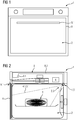
- Fig. 1 shows a schematic illustration of a food preparation entity 1.
- the food preparation entity 1 is a baking oven.
- the food preparation entity 1 should not be considered limited to such baking oven.
- the food preparation entity 1 may also be a microwave appliance, a steam oven etc.
- the food preparation entity 1 comprises a base body in which a cavity 2 for receiving food 3 to be prepared is provided.
- the food preparation entity 1 may comprise a door 9 with a door handle 9.1 for closing the cavity 2 during the food preparation process.
- the food preparation entity 1 comprises an image capturing system.
- the image capturing system comprises at least two cameras 4, 5, specifically digital cameras adapted to capture optical information of the food 3 received within the cavity 2. Said optical information may be digital images.
- a processing entity 6 of the food preparation entity 1 establishes three-dimensional (3D) information of said food 3 received within the cavity 2.
- 3D three-dimensional
- a pair of cameras 4, 5 is included in the cavity 2.
- the food preparation entity 1 may comprise more than two cameras.
- the cameras 4, 5 may be included in an upper region of the cavity 2 of the food preparation entity 1. More in detail, the cameras 4, 5 may be placed above the food 3 in order to be able to capture images from an upper side, specifically according to a slanted top-down view.
- the cameras 4, 5 may comprise the same or different functions, technologies and optical characteristics.
- the cameras 4, 5 may be of monochrome or color type, a infrared or plenoptic camera, may have the same or different aperture, focal length or resolution.
- the cameras 4, 5 may have multiple or automatic focal points or may have a matrix optic.
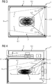
- Fig. 2 and 3 show a first embodiment of the food preparation entity from different points of view.
- the cameras 4, 5 are included in the cavity 2. More in detail, the cameras 4, 5 are spatially distributed along a horizontal axis in an upper edge 2.3. For example, the cameras 4, 5 are arranged in opposite upper corners 2.1, 2.2 of the cavity 2 which are located opposite to the door 9. However, the arrangement of the cameras 4, 5 in opposite upper corners 2.1, 2.2 averted from the door 9 is only a mere example.
- the cameras 4, 5 can be arranged closer together at the horizontal edge 2.3 of the cavity 2, i.e. not in the corner regions but at a certain distance to said corners 2.1, 2.2.
- the cameras 4, 5 provide a certain field of view 4.1, 5.1 (as indicated by the dashed lines).
- Said field of view 4.1, 5.1 is mainly influenced by the detection angle of the camera.
- Said field of view 4.1, 5.1 may be, depending on the technology of the camera, fixed or variable.
- a variable field of view may be obtained by a linear movement of the camera.
- a variable field of view may be obtained by a linear movement of the camera.
- the fields of view 4.1, 5.1 of different cameras 4, 5 may at least partially overlap in order to improve the calculation of 3D-information of the food 3. Said overlapping may be achieved by a suitable arrangement of cameras 4, 5 in the cavity 2 and/or an angular alignment of cameras 4, 5 with respect to a central area of the cavity 2, in which the food 3 to be prepared is typically received.
- Each camera 4, 5 may comprise a main view axis 4.2, 5.2.
- the main view axis of a camera may be an axis arranged in the centre of its field of view and/or may be an axis which extends between a central portion of the cavity 2 and the respective camera 4, 5.
- the main view axes 4.2, 5.2 of the cameras may include an angle ⁇ in the range of 1° and 89°.
- the angle ⁇ may be in the range of 5° to 30°, more preferably in the range of 10° to 15°, specifically 11°, 12°, 13° or 14°.
- Fig. 4 and 5 show a further example embodiment of a food preparation appliance 1 with a different configuration of the image capturing system.
- the cameras 4, 5 are not spaced in a horizontal direction but are spatially distributed along a vertical or essentially vertical axis.
- a first camera 4 may be arranged in the centre or essentially in the centre of the upper rear edge 2.3 of the cavity 2. Said upper rear edge 2.3 may be arranged at a distance and opposite to the door 9.
- the second camera 5 may be arranged below the first camera 5.
- the distance between the first and the second camera 4, 5 may be in the range of 2cm to 40cm, specifically in the range of 5cm to 15cm. Thereby, the cameras 4, 5 are able to provide images from slightly different points of view, both in a slanted top-down direction.
- the cameras 4, 5 may be attached to the inner wall of the cavity 2 or may be at least partially included in a recess provided in said cavity wall (partial or full camera integration).
- At least one camera may be included in the door 9.
- the camera may be included in the main body of the door 9, for example in the door frame.
- the camera may be included or attached to the door handle 9.1 and aligned such that the camera is able to capture images through a window provided in the door 9.
- the cameras 4, 5 are operatively coupled with cooling means 8.
- the cooling means 8 are configured to ensure a cooling of the camera 4, 5 such that images with a suitable image quality can be captured without greater impact of the temperature provided within the cavity.
- the cooling means 8 may use different kinds of cooling media, for example air, water or another cooling liquid.
- the cooling means 8 cooling the cameras 4, 5 may operatively coupled with a cooling arrangement of the food preparation entity 1 which provides a cooling of another entity of the food preparation entity 1 (e.g. a fan provides an air stream to a processing unit as well to the camera or a heat exchanger coupled with the camera).
- the cameras 4, 5 may comprise separate cooling means 8 which only provide cooling of the cameras 4, 5 (and not for other operational entities of the food preparation entity 1).
- the two or more cameras 4, 5 may comprise a common cooling system, i.e. may share at least some components of a common cooling system or each camera 4, 5 may comprise its own cooling system (i.e. a separated cooling system for each camera 4, 5).
- the cooling means 8 may comprise, as shown in fig. 2 to 5 a liquid-based cooling system. More in detail, the cooling means 8 may comprise a tubing 8.2 and a heat exchanger 8.1, wherein said tubing 8.2 couples one or more cameras 4, 5 with said heat exchanger 8.1.
- a cooling liquid for example water, may circulate through the cooling system. Thereby heat from one or more cameras 4, 5 is transferred to the cooling liquid and transported to the heat exchanger 8.1 in order to provide a cooling effect at the camera(s) 4, 5.
- the heat exchanger 8.1 may be built by a surface portion of the food preparation entity 1, e.g. a cooler surface area of a housing portion or the heat exchanger 8.1 may be a separate entity specifically adapted for heat exchange (e.g. an entity comprising cooling ribs).
- a pump may be used for providing the circulation of the cooling liquid.
- the cameras 4, 5 may be cooled by an air stream.
- a blower may be directly attached to the respective camera 4, 5 or an air duct may be used for providing an air stream generated by a fan to the cameras 4, 5.
- the fan may be a fan configured to merely cool down one or more of said cameras 4, 5.
- an air stream provided by a fan used for cooling other entities (e.g. electronics, door glass etc.) of the food preparation entity 1 can be also used for cooling the cameras 4, 5.
- a heat pipe may be used for cooling the cameras 4, 5.
- Said heat pipe may be coupled with the camera 4, 5 at a first end and may transport the heat due to its high heat conductivity to a heat exchanger or a surface portion of the food preparation entity 1 (e.g. a housing portion arranged in a lower temperature region than the cameras 4, 5).
- the captured images can be used for providing a gesture control.
- the captured images may be analysed by the processing entity 6 in order to recognise certain gestures of a user in front of the food preparation entity 1 in order to control the food preparation entity 1 based on the recognized gestures.
Landscapes
- Engineering & Computer Science (AREA)
- Mechanical Engineering (AREA)
- Multimedia (AREA)
- Signal Processing (AREA)
- General Engineering & Computer Science (AREA)
- Chemical & Material Sciences (AREA)
- Combustion & Propulsion (AREA)
- Physics & Mathematics (AREA)
- Computer Vision & Pattern Recognition (AREA)
- General Physics & Mathematics (AREA)
- Theoretical Computer Science (AREA)
- Electromagnetism (AREA)
- Cold Air Circulating Systems And Constructional Details In Refrigerators (AREA)
- Closed-Circuit Television Systems (AREA)
- Electric Ovens (AREA)
Abstract
Description
- The present invention relates generally to the field of food preparation entities. More specifically, the present invention is related to a food preparation entity adapted to determine the three-dimensional shape of food received within a cavity of the food preparation entity.
- Food preparation entities, for example baking ovens, are well known in prior art. Such food preparation entities comprise a cavity for receiving food to be cooked or baked and a door for closing the cavity during the food preparation process. The food preparation entity may comprise an image recognition system for capturing optical information of said food received within the cavity.
- It is an objective of embodiments of the present invention to provide a food preparation entity which is adapted to establish reliable three-dimensional information of the food to be cooked based on optical information with limited technical effort. The objective is solved by the features of the independent claims. Preferred embodiments are given in the dependent claims. If not explicitly indicated otherwise, embodiments of the invention can be freely combined with each other.
- According to a first aspect, the invention relates to a food preparation entity comprising a cavity for receiving food to be prepared and at least two cameras for capturing images of the food included in the cavity. Said cameras are positioned such that images are captured from different points of view. Each camera comprises a certain field of view, wherein immediately adjacent fields of view of said cameras at least partially overlap. A processing entity is provided which is configured to calculate three-dimensional (3D) information of the food included in the cavity based on the images provided by the cameras.
- Said food preparation entity is advantageous because based on said cameras with partially overlapping fields of view, reliable 3D-information can be gathered with reduced technical effort.
- According to embodiments, each camera comprises a main view axis and the angle between the main view axes of cameras providing immediately adjacent fields of view is in the range between 1° and 89°, preferably between 5° and 30°, more preferably between 10° and 15°, most preferably 11°, 12°, 13° or 14°. Using said alignment rules, the fields of view of the cameras are positioned with respect to each other such that precise 3D-information with improved texture extraction can be obtained.
- According to embodiments, at least one camera is coupled with cooling means for cooling the camera. Said cameras may be included in the cavity. More in detail, the cameras may be attached to the cavity wall or included in a recess of said cavity wall. Thereby it is possible to use cameras with lower temperature requirements for recording the interior of the cavity.
- The cameras may share common cooling means or each camera may comprise its own cooling means.
- According to embodiments, the cooling means use air or a cooling liquid as heat transfer medium. Thereby a regional cooling effect at the respective camera can be obtained.
- According to embodiments, the cooling means may comprise an air duct, a heat pipe or a liquid-based cooling system. Based on said cooling entities, an improved cooling of the camera can be achieved.
- According to embodiments, the cooling means comprise a heat sink provided by a surface portion of the food preparation entity or provided by a heat exchanger. Thermal energy may be transported by air, a heat pipe or a cooling liquid from the camera to the heat sink in order to provide a cooling effect at the camera.
- According to embodiments, the cooling means comprise a heat exchanger operatively coupled with a cooling arrangement of the food preparation entity. Said cooling arrangement may be used not only for cooling the cameras but may be also used for cooling other entities of the food preparation entity, for example electronics, the oven door glass etc. The cooling arrangement may, for example, comprise a fan for generating an air flow through to the heat exchanger.
- According to embodiments, the cooling means comprise a liquid-based cooling system including a pump, a heat exchanger and a tubing for providing a liquid circulation between at least one camera and the heat exchanger. Using such liquid-based cooling system, a high cooling effect at the camera can be obtained. The tubing, respectively, the liquid-based cooling system may include one or more cameras in order to provide a cooling effect at a single camera or multiple cameras.
- According to embodiments, the at least two cameras are included in the cavity. The cameras may be arranged to capture images from a top view, specifically from a slanted top view. Thereby an improved integration into the food preparation entity can be obtained.
- According to embodiments, at least one camera is included in the cavity and at least one further camera is included in a door handle of a door of the food preparation entity. Thereby it is possible to obtain images from different points of view.
- According to embodiments, the at least two cameras are included in the door handle of a door of the food preparation entity. Thereby, cooling means for cooling the cameras can be avoided because the heat impact on the cameras included in the door handle is quite low.
- According to embodiments, at least one camera provides a field of view from the interior of the cavity through a door glass of a door of the food preparation entity and a processing entity is configured to provide gesture control based on the information provided by said camera. Thereby, the camera providing images for generating 3D-information of the food to be prepared can be further used for gathering information for gesture control.
- According to a further aspect, the invention relates to a method for gathering three-dimensional information of food received within a cavity of a food preparation entity based on at least two cameras. The method comprises the steps of:
- capturing images by the at least two cameras from different points of view, wherein each camera comprises a certain field of view, wherein immediately adjacent fields of view of said cameras at least partially overlap;
- calculating three-dimensional information of the food included in the cavity based on the images provided by the cameras.
- According to embodiments, the cameras are cooled by cooling means. Thereby the heat impact on the cameras can be reduced and cameras configured for low temperature applications can be used for capturing the images.
- According to embodiments, the images are captured by cameras comprising main view axes and the angle between the main view axes of cameras providing immediately adjacent fields of view is in the range between 1° and 89°, preferably between 5° and 30°, more preferably between 10° and 15°, most preferably 11°, 12°, 13° or 14°.
- The term "food preparation entity" as used in the present disclosure may refer to any appliance which can be used for preparing food, specifically ovens, steam ovens, microwave ovens or similar frying, baking or cooking appliances.
- The term "essentially" or "approximately" as used in the present disclosure means deviations from the exact value by +/- 10%, preferably by +/- 5% and/or deviations in the form of changes that are insignificant for the function.
- The various aspects of the invention, including its particular features and advantages, will be readily understood from the following detailed description and the accompanying drawings, in which:
- Fig. 1
- shows an example schematic view of a food preparation entity;
- Fig. 2
- shows a first embodiment of a food preparation entity with a first camera arrangement in a lateral sectional view;
- Fig. 3
- shows a first embodiment of a food preparation entity with a first camera arrangement in a top sectional view;
- Fig. 4
- shows a second embodiment of a food preparation entity with a second camera arrangement in a lateral sectional view; and
- Fig. 5
- shows a second embodiment of a food preparation entity with a second camera arrangement in a top sectional view;
- The present invention will now be described more fully with reference to the accompanying drawings, in which example embodiments are shown. However, this invention should not be construed as limited to the embodiments set forth herein. Throughout the following description similar reference numerals have been used to denote similar elements, parts, items or features, when applicable.
-
Fig. 1 shows a schematic illustration of a food preparation entity 1. In the present example, the food preparation entity 1 is a baking oven. However, the food preparation entity 1 should not be considered limited to such baking oven. The food preparation entity 1 may also be a microwave appliance, a steam oven etc. The food preparation entity 1 comprises a base body in which acavity 2 for receivingfood 3 to be prepared is provided. The food preparation entity 1 may comprise a door 9 with a door handle 9.1 for closing thecavity 2 during the food preparation process. - In addition, the food preparation entity 1 comprises an image capturing system. The image capturing system comprises at least two
cameras 4, 5, specifically digital cameras adapted to capture optical information of thefood 3 received within thecavity 2. Said optical information may be digital images. Based on said digital images, aprocessing entity 6 of the food preparation entity 1 establishes three-dimensional (3D) information of saidfood 3 received within thecavity 2. In the following embodiments, a pair ofcameras 4, 5 is included in thecavity 2. However, according to other embodiments, the food preparation entity 1 may comprise more than two cameras. - Preferably, the
cameras 4, 5 may be included in an upper region of thecavity 2 of the food preparation entity 1. More in detail, thecameras 4, 5 may be placed above thefood 3 in order to be able to capture images from an upper side, specifically according to a slanted top-down view. - The
cameras 4, 5 may comprise the same or different functions, technologies and optical characteristics. For example, thecameras 4, 5 may be of monochrome or color type, a infrared or plenoptic camera, may have the same or different aperture, focal length or resolution. In addition, thecameras 4, 5 may have multiple or automatic focal points or may have a matrix optic. -
Fig. 2 and3 show a first embodiment of the food preparation entity from different points of view. Thecameras 4, 5 are included in thecavity 2. More in detail, thecameras 4, 5 are spatially distributed along a horizontal axis in an upper edge 2.3. For example, thecameras 4, 5 are arranged in opposite upper corners 2.1, 2.2 of thecavity 2 which are located opposite to the door 9. However, the arrangement of thecameras 4, 5 in opposite upper corners 2.1, 2.2 averted from the door 9 is only a mere example. Thecameras 4, 5 can be arranged closer together at the horizontal edge 2.3 of thecavity 2, i.e. not in the corner regions but at a certain distance to said corners 2.1, 2.2. - As shown in
Fig. 2 and3 , thecameras 4, 5 provide a certain field of view 4.1, 5.1 (as indicated by the dashed lines). Said field of view 4.1, 5.1 is mainly influenced by the detection angle of the camera. Said field of view 4.1, 5.1 may be, depending on the technology of the camera, fixed or variable. For example, a variable field of view may be obtained by a linear movement of the camera. For example, a variable field of view may be obtained by a linear movement of the camera. - The fields of view 4.1, 5.1 of
different cameras 4, 5 may at least partially overlap in order to improve the calculation of 3D-information of thefood 3. Said overlapping may be achieved by a suitable arrangement ofcameras 4, 5 in thecavity 2 and/or an angular alignment ofcameras 4, 5 with respect to a central area of thecavity 2, in which thefood 3 to be prepared is typically received. - Each
camera 4, 5 may comprise a main view axis 4.2, 5.2. The main view axis of a camera may be an axis arranged in the centre of its field of view and/or may be an axis which extends between a central portion of thecavity 2 and therespective camera 4, 5. - In order to further improve the calculation of 3D-information of the
food 3, the main view axes 4.2, 5.2 of the cameras may include an angle α in the range of 1° and 89°. Preferably, the angle α may be in the range of 5° to 30°, more preferably in the range of 10° to 15°, specifically 11°, 12°, 13° or 14°. Using said angles α, thefood 3 is recorded from slightly different perspectives which leads to better texture extraction possibilities and an improved basis for calculating 3D-information. -
Fig. 4 and5 show a further example embodiment of a food preparation appliance 1 with a different configuration of the image capturing system. Thecameras 4, 5 are not spaced in a horizontal direction but are spatially distributed along a vertical or essentially vertical axis. - As shown in
fig. 4 and5 , afirst camera 4 may be arranged in the centre or essentially in the centre of the upper rear edge 2.3 of thecavity 2. Said upper rear edge 2.3 may be arranged at a distance and opposite to the door 9. The second camera 5 may be arranged below the first camera 5. The distance between the first and thesecond camera 4, 5 may be in the range of 2cm to 40cm, specifically in the range of 5cm to 15cm. Thereby, thecameras 4, 5 are able to provide images from slightly different points of view, both in a slanted top-down direction. - The
cameras 4, 5 according to the embodiments ofFig. 2 to 5 may be attached to the inner wall of thecavity 2 or may be at least partially included in a recess provided in said cavity wall (partial or full camera integration). - According to yet another configuration of the image capturing system (not shown in the figures), at least one camera may be included in the door 9. The camera may be included in the main body of the door 9, for example in the door frame. According to another embodiment, the camera may be included or attached to the door handle 9.1 and aligned such that the camera is able to capture images through a window provided in the door 9.
- Typically, in food preparation entities 1 high temperature values occur. In order to avoid damage of the
cameras 4, 5 and/or degraded image capturing conditions (especially of CCD sensors), thecameras 4, 5 are operatively coupled with cooling means 8. The cooling means 8 are configured to ensure a cooling of thecamera 4, 5 such that images with a suitable image quality can be captured without greater impact of the temperature provided within the cavity. - The cooling means 8 may use different kinds of cooling media, for example air, water or another cooling liquid. The cooling means 8 cooling the
cameras 4, 5 may operatively coupled with a cooling arrangement of the food preparation entity 1 which provides a cooling of another entity of the food preparation entity 1 (e.g. a fan provides an air stream to a processing unit as well to the camera or a heat exchanger coupled with the camera). According to another embodiment, thecameras 4, 5 may comprise separate cooling means 8 which only provide cooling of thecameras 4, 5 (and not for other operational entities of the food preparation entity 1). The two ormore cameras 4, 5 may comprise a common cooling system, i.e. may share at least some components of a common cooling system or eachcamera 4, 5 may comprise its own cooling system (i.e. a separated cooling system for eachcamera 4, 5). - According to an embodiment, the cooling means 8 may comprise, as shown in
fig. 2 to 5 a liquid-based cooling system. More in detail, the cooling means 8 may comprise a tubing 8.2 and a heat exchanger 8.1, wherein said tubing 8.2 couples one ormore cameras 4, 5 with said heat exchanger 8.1. A cooling liquid, for example water, may circulate through the cooling system. Thereby heat from one ormore cameras 4, 5 is transferred to the cooling liquid and transported to the heat exchanger 8.1 in order to provide a cooling effect at the camera(s) 4, 5. The heat exchanger 8.1 may be built by a surface portion of the food preparation entity 1, e.g. a cooler surface area of a housing portion or the heat exchanger 8.1 may be a separate entity specifically adapted for heat exchange (e.g. an entity comprising cooling ribs). A pump may be used for providing the circulation of the cooling liquid. - According to another embodiment, the
cameras 4, 5 may be cooled by an air stream. For example, a blower may be directly attached to therespective camera 4, 5 or an air duct may be used for providing an air stream generated by a fan to thecameras 4, 5. The fan may be a fan configured to merely cool down one or more of saidcameras 4, 5. However, an air stream provided by a fan used for cooling other entities (e.g. electronics, door glass etc.) of the food preparation entity 1 can be also used for cooling thecameras 4, 5. - According to yet another embodiment, a heat pipe may be used for cooling the
cameras 4, 5. Said heat pipe may be coupled with thecamera 4, 5 at a first end and may transport the heat due to its high heat conductivity to a heat exchanger or a surface portion of the food preparation entity 1 (e.g. a housing portion arranged in a lower temperature region than thecameras 4, 5). - In case that at least one of said
cameras 4, 5 has a field of view such that a region in front of the door glass can be captured by thecamera 4, 5 (i.e.camera 4, 5 can capture images through the door glass), the captured images can be used for providing a gesture control. For example, the captured images may be analysed by theprocessing entity 6 in order to recognise certain gestures of a user in front of the food preparation entity 1 in order to control the food preparation entity 1 based on the recognized gestures. - It should be noted that the description and drawings merely illustrate the principles of the proposed method and food preparation entity. Those skilled in the art will be able to implement various arrangements that, although not explicitly described or shown herein, embody the principles of the invention.
-
- 1
- Food preparation entity
- 2
- cavity
- 2.1
- corner
- 2.2
- corner
- 2.3
- edge
- 3
- food
- 4
- camera
- 4.1
- first field of view
- 4.2
- main view axis
- 5
- second camera
- 5.1
- field of view
- 5.2
- main view axis
- 6
- processing entity
- 8
- cooling means
- 8.1
- heat exchanger
- 8.2
- tubing
- 9
- door
- 9.1
- door handle
- α
- angle
Claims (15)
- Food preparation entity comprising a cavity (2) for receiving food (3) to be prepared and at least two cameras (4, 5) for capturing images of the food (3) included in the cavity (2), wherein said cameras (4, 5) are positioned such that images are captured from different points of view, wherein each camera (4, 5) comprises a certain field of view (4.1, 5.1), wherein immediately adjacent fields of view (4.1, 5.1) of said cameras (4, 5) at least partially overlap and wherein a processing entity (6) is provided which is configured to calculate three-dimensional information of the food (3) included in the cavity (2) based on the images provided by the cameras (4, 5).
- Food preparation entity according to claim 1, wherein each camera (4, 5) comprises a main view axis (4.2, 5.2) and the angle (α) between the main view axes (4.2, 5.2) of cameras (4, 5) providing immediately adjacent fields of view (4.1, 5.1) is in the range between 1° and 89°, preferably between 5° and 30°, more preferably between 10° and 15°, most preferably 11°, 12°, 13° or 14°.
- Food preparation entity according to claim 1 or 2, wherein at least one camera (4, 5) is coupled with cooling means (8) for cooling the camera (4, 5).
- Food preparation entity according to claim 3, wherein the cooling means (8) use air or a cooling liquid as heat transfer medium.
- Food preparation entity according to claim 3 or 4, wherein the cooling means (8) comprise an air duct, a heat pipe or a liquid-based cooling system.
- Food preparation entity according to anyone of claims 3 to 5, wherein the cooling means (8) comprise a heat sink provided by a surface portion of the food preparation entity (1) or provided by a heat exchanger (8.1).
- Food preparation entity according to anyone of claims 3 to 6, wherein the cooling means (8) comprise a heat exchanger (8.1) operatively coupled with a cooling arrangement of the food preparation entity (1).
- Food preparation entity according to anyone of claims 3 to 7, wherein the cooling means (8) comprise a liquid-based cooling system including a pump, a heat exchanger (8.1) and a tubing (8.2) for providing a liquid flow circulation between at least one camera (4, 5) and the heat exchanger (8.1).
- Food preparation entity according to anyone of the preceding claims, wherein the at least two cameras (4, 5) are included in the cavity (2).
- Food preparation entity according to anyone of claims 1 to 8, wherein at least one camera (4, 5) is included in the cavity (2) and at least one further camera (4, 5) is included in a door handle (9.1) of a door (9) of the food preparation entity (1).
- Food preparation entity according to anyone of claims 1 to 8, wherein the at least two cameras (4, 5) are included in the door handle (9.1) of a door (9) of the food preparation entity (1).
- Food preparation entity according to anyone of the preceding claims, wherein at least one camera (4, 5) provides a field of view from the interior of the cavity (2) through a door glass of a door (9) of the food preparation entity (1) and a processing entity is configured to provide gesture control based on the information provided by said camera (4, 5).
- Method for gathering three-dimensional information of food (3) received within a cavity (2) of a food preparation entity (1) based on at least two cameras (4, 5), the method comprising the steps of :- capturing images by the at least two cameras (4, 5) from different points of view, wherein each camera (4, 5) comprises a certain field of view (4.1, 5.1), wherein immediately adjacent fields of view (4.1, 5.1) of said cameras (4, 5) at least partially overlap;- calculating three-dimensional information of the food (3) included in the cavity (2) based on the images provided by the cameras (4, 5).
- Method according to claim 13, wherein the cameras (4, 5) are cooled by cooling means (8).
- Method according to claim 13 or 14, wherein the images are captured by cameras (4, 5) comprising main view axes (4.2, 5.2) and the angle (α) between the main view axes (4.2, 5.2) of cameras (4, 5) providing immediately adjacent fields of view (4.1, 5.1) is in the range between 1° and 89°, preferably between 5° and 30°, more preferably between 10° and 15°, most preferably 11°, 12°, 13° or 14°.
Priority Applications (5)
| Application Number | Priority Date | Filing Date | Title |
|---|---|---|---|
| EP18212055.0A EP3667173B1 (en) | 2018-12-12 | 2018-12-12 | Food preparation entity |
| CN201980081661.2A CN113167478A (en) | 2018-12-12 | 2019-11-29 | Food preparation entity |
| US17/413,190 US11909943B2 (en) | 2018-12-12 | 2019-11-29 | Food preparation entity |
| AU2019396393A AU2019396393B2 (en) | 2018-12-12 | 2019-11-29 | Food preparation entity |
| PCT/EP2019/083067 WO2020120172A1 (en) | 2018-12-12 | 2019-11-29 | Food preparation entity |
Applications Claiming Priority (1)
| Application Number | Priority Date | Filing Date | Title |
|---|---|---|---|
| EP18212055.0A EP3667173B1 (en) | 2018-12-12 | 2018-12-12 | Food preparation entity |
Publications (2)
| Publication Number | Publication Date |
|---|---|
| EP3667173A1 true EP3667173A1 (en) | 2020-06-17 |
| EP3667173B1 EP3667173B1 (en) | 2023-06-07 |
Family
ID=64665181
Family Applications (1)
| Application Number | Title | Priority Date | Filing Date |
|---|---|---|---|
| EP18212055.0A Active EP3667173B1 (en) | 2018-12-12 | 2018-12-12 | Food preparation entity |
Country Status (5)
| Country | Link |
|---|---|
| US (1) | US11909943B2 (en) |
| EP (1) | EP3667173B1 (en) |
| CN (1) | CN113167478A (en) |
| AU (1) | AU2019396393B2 (en) |
| WO (1) | WO2020120172A1 (en) |
Cited By (4)
| Publication number | Priority date | Publication date | Assignee | Title |
|---|---|---|---|---|
| IT202000017362A1 (en) * | 2020-07-16 | 2022-01-16 | Rational Ag | COOKING DEVICE AND PROCEDURE FOR OPERATING A COOKING DEVICE |
| WO2022148591A1 (en) * | 2021-01-06 | 2022-07-14 | BSH Hausgeräte GmbH | Household appliance including reflective door |
| JP2022187423A (en) * | 2021-06-07 | 2022-12-19 | 日立グローバルライフソリューションズ株式会社 | heating cooker |
| EP4105559A1 (en) * | 2021-06-17 | 2022-12-21 | Whirlpool Corporation | Stereovision monitoring system for cooking appliance |
Families Citing this family (2)
| Publication number | Priority date | Publication date | Assignee | Title |
|---|---|---|---|---|
| WO2022002589A1 (en) * | 2020-07-01 | 2022-01-06 | BSH Hausgeräte GmbH | Food preparation apparatus and method for food preparation |
| US20240093874A1 (en) * | 2022-09-15 | 2024-03-21 | Samsung Electronics Co., Ltd. | Cooking device |
Citations (7)
| Publication number | Priority date | Publication date | Assignee | Title |
|---|---|---|---|---|
| US20140048055A1 (en) * | 2011-04-29 | 2014-02-20 | Electrolux Home Products Corporation N.V. | Baking oven door and baking oven |
| US20140203012A1 (en) * | 2013-01-23 | 2014-07-24 | Whirlpool Corporation | Microwave oven multiview silhouette volume calculation for mass estimation |
| US20150305543A1 (en) * | 2014-04-07 | 2015-10-29 | Indesit Company S.P.A. | Oven comprising weight sensors |
| KR101635162B1 (en) * | 2016-02-25 | 2016-06-30 | (주)송우인포텍 | Cooling device for surveillance camera |
| US20170261213A1 (en) * | 2016-03-11 | 2017-09-14 | Samsung Electronics Co., Ltd. | Oven and control method thereof |
| US20180292093A1 (en) * | 2015-05-05 | 2018-10-11 | June Life, Inc. | Connected food preparation system and method of use |
| JP2018169133A (en) * | 2017-03-30 | 2018-11-01 | 大阪瓦斯株式会社 | Heating cooker |
Family Cites Families (14)
| Publication number | Priority date | Publication date | Assignee | Title |
|---|---|---|---|---|
| EP2268049A3 (en) * | 2002-04-25 | 2013-06-05 | Sharp Kabushiki Kaisha | Image data creation device, image data reproduction device, and image data recording medium |
| US20110254939A1 (en) * | 2010-04-16 | 2011-10-20 | Tatiana Pavlovna Kadantseva | Detecting User Input Provided To A Projected User Interface |
| KR20120028121A (en) * | 2010-09-14 | 2012-03-22 | 삼성전자주식회사 | Method and apparatus for diciding of convergence angle in stereo camera |
| US20130149651A1 (en) * | 2011-12-07 | 2013-06-13 | Mike THIELVOLDT | Standalone flame effect |
| EP2618634A1 (en) * | 2012-01-23 | 2013-07-24 | Whirlpool Corporation | Microwave heating apparatus |
| JP6364607B2 (en) * | 2014-01-23 | 2018-08-01 | パナソニックIpマネジメント株式会社 | Cooker |
| CA2942009A1 (en) * | 2014-03-19 | 2015-09-24 | Visunex Medical Systems Co. Ltd. | Eye imaging apparatus and systems |
| DE102014210668A1 (en) * | 2014-06-05 | 2015-12-17 | BSH Hausgeräte GmbH | Home appliance with food-handling room and camera |
| AU2016218046B2 (en) * | 2015-02-10 | 2021-03-11 | Electrolux Appliances Aktiebolag | Oven door and oven comprising an oven door |
| EP3346190B1 (en) * | 2017-01-10 | 2020-05-06 | Electrolux Appliances Aktiebolag | Food preparation entity |
| CN207354502U (en) * | 2017-03-07 | 2018-05-11 | 上海中科顶信医学影像科技有限公司 | Capture apparatus for three-dimensional imaging |
| CN206757709U (en) * | 2017-04-17 | 2017-12-15 | 嘉兴超维信息技术有限公司 | A kind of three-dimensional modeling equipment |
| CN108174470B (en) * | 2017-12-20 | 2021-05-18 | 广东美的厨房电器制造有限公司 | Control method and device for cooking equipment and cooking equipment |
| US11116050B1 (en) * | 2018-02-08 | 2021-09-07 | June Life, Inc. | High heat in-situ camera systems and operation methods |
-
2018
- 2018-12-12 EP EP18212055.0A patent/EP3667173B1/en active Active
-
2019
- 2019-11-29 AU AU2019396393A patent/AU2019396393B2/en active Active
- 2019-11-29 US US17/413,190 patent/US11909943B2/en active Active
- 2019-11-29 CN CN201980081661.2A patent/CN113167478A/en active Pending
- 2019-11-29 WO PCT/EP2019/083067 patent/WO2020120172A1/en not_active Ceased
Patent Citations (7)
| Publication number | Priority date | Publication date | Assignee | Title |
|---|---|---|---|---|
| US20140048055A1 (en) * | 2011-04-29 | 2014-02-20 | Electrolux Home Products Corporation N.V. | Baking oven door and baking oven |
| US20140203012A1 (en) * | 2013-01-23 | 2014-07-24 | Whirlpool Corporation | Microwave oven multiview silhouette volume calculation for mass estimation |
| US20150305543A1 (en) * | 2014-04-07 | 2015-10-29 | Indesit Company S.P.A. | Oven comprising weight sensors |
| US20180292093A1 (en) * | 2015-05-05 | 2018-10-11 | June Life, Inc. | Connected food preparation system and method of use |
| KR101635162B1 (en) * | 2016-02-25 | 2016-06-30 | (주)송우인포텍 | Cooling device for surveillance camera |
| US20170261213A1 (en) * | 2016-03-11 | 2017-09-14 | Samsung Electronics Co., Ltd. | Oven and control method thereof |
| JP2018169133A (en) * | 2017-03-30 | 2018-11-01 | 大阪瓦斯株式会社 | Heating cooker |
Cited By (5)
| Publication number | Priority date | Publication date | Assignee | Title |
|---|---|---|---|---|
| IT202000017362A1 (en) * | 2020-07-16 | 2022-01-16 | Rational Ag | COOKING DEVICE AND PROCEDURE FOR OPERATING A COOKING DEVICE |
| WO2022148591A1 (en) * | 2021-01-06 | 2022-07-14 | BSH Hausgeräte GmbH | Household appliance including reflective door |
| JP2022187423A (en) * | 2021-06-07 | 2022-12-19 | 日立グローバルライフソリューションズ株式会社 | heating cooker |
| EP4105559A1 (en) * | 2021-06-17 | 2022-12-21 | Whirlpool Corporation | Stereovision monitoring system for cooking appliance |
| US12089777B2 (en) | 2021-06-17 | 2024-09-17 | Whirlpool Corporation | Stereovision monitoring system for cooking appliance |
Also Published As
| Publication number | Publication date |
|---|---|
| EP3667173B1 (en) | 2023-06-07 |
| CN113167478A (en) | 2021-07-23 |
| US11909943B2 (en) | 2024-02-20 |
| US20220021865A1 (en) | 2022-01-20 |
| WO2020120172A1 (en) | 2020-06-18 |
| AU2019396393B2 (en) | 2025-02-27 |
| AU2019396393A1 (en) | 2021-05-20 |
Similar Documents
| Publication | Publication Date | Title |
|---|---|---|
| AU2019396393B2 (en) | Food preparation entity | |
| US12253268B1 (en) | Appliance with gaseous colloid management system and method of use | |
| US10819905B1 (en) | System and method for temperature sensing in cooking appliance with data fusion | |
| US11674692B2 (en) | Food preparation entity | |
| US11765798B2 (en) | High heat in-situ camera systems and operation methods | |
| EP4224078B1 (en) | Room information inferring apparatus, room information inferring method, and air conditioning apparatus | |
| US11619451B2 (en) | Oven having an imaging device | |
| JP7542642B2 (en) | Condensation prevention system and method | |
| CN106093062B (en) | A CCD-based intelligent soot blowing system for ash and slagging of boiler heating area | |
| EP3667172A1 (en) | Cooking oven with camera | |
| JP6576568B2 (en) | Air conditioning system | |
| CN104287640A (en) | Oven with function of shooing | |
| CN110291331A (en) | Cooking appliance with removable sensor module | |
| EP4411636A1 (en) | Image processing for an appliance | |
| US20240310053A1 (en) | Heating cooker | |
| CN114938920B (en) | Oven and control method thereof | |
| CN112273987A (en) | Control method of steam cooking equipment and steam cooking equipment | |
| CN211239932U (en) | an oven | |
| US20240288176A1 (en) | Cooking appliance with a camera for monitoring the cooking chamber | |
| EP4411247B1 (en) | Heating cooker | |
| CN223726279U (en) | Machine vision light source with internal circulation heat radiation system | |
| CN114689582B (en) | Commodity purity detection method for vertical air curtain cabinet | |
| US20260009544A1 (en) | Cooking appliance comprising viewing window and image sensor for capturing images through the viewing window | |
| GB2633175A (en) | Directing an airflow towards a human | |
| CN110513813A (en) | Heat pump air conditioner state adjusts platform |
Legal Events
| Date | Code | Title | Description |
|---|---|---|---|
| PUAI | Public reference made under article 153(3) epc to a published international application that has entered the european phase |
Free format text: ORIGINAL CODE: 0009012 |
|
| STAA | Information on the status of an ep patent application or granted ep patent |
Free format text: STATUS: THE APPLICATION HAS BEEN PUBLISHED |
|
| AK | Designated contracting states |
Kind code of ref document: A1 Designated state(s): AL AT BE BG CH CY CZ DE DK EE ES FI FR GB GR HR HU IE IS IT LI LT LU LV MC MK MT NL NO PL PT RO RS SE SI SK SM TR |
|
| AX | Request for extension of the european patent |
Extension state: BA ME |
|
| STAA | Information on the status of an ep patent application or granted ep patent |
Free format text: STATUS: REQUEST FOR EXAMINATION WAS MADE |
|
| 17P | Request for examination filed |
Effective date: 20201217 |
|
| RBV | Designated contracting states (corrected) |
Designated state(s): AL AT BE BG CH CY CZ DE DK EE ES FI FR GB GR HR HU IE IS IT LI LT LU LV MC MK MT NL NO PL PT RO RS SE SI SK SM TR |
|
| STAA | Information on the status of an ep patent application or granted ep patent |
Free format text: STATUS: EXAMINATION IS IN PROGRESS |
|
| 17Q | First examination report despatched |
Effective date: 20210715 |
|
| GRAP | Despatch of communication of intention to grant a patent |
Free format text: ORIGINAL CODE: EPIDOSNIGR1 |
|
| STAA | Information on the status of an ep patent application or granted ep patent |
Free format text: STATUS: GRANT OF PATENT IS INTENDED |
|
| INTG | Intention to grant announced |
Effective date: 20221129 |
|
| GRAS | Grant fee paid |
Free format text: ORIGINAL CODE: EPIDOSNIGR3 |
|
| GRAA | (expected) grant |
Free format text: ORIGINAL CODE: 0009210 |
|
| STAA | Information on the status of an ep patent application or granted ep patent |
Free format text: STATUS: THE PATENT HAS BEEN GRANTED |
|
| AK | Designated contracting states |
Kind code of ref document: B1 Designated state(s): AL AT BE BG CH CY CZ DE DK EE ES FI FR GB GR HR HU IE IS IT LI LT LU LV MC MK MT NL NO PL PT RO RS SE SI SK SM TR |
|
| REG | Reference to a national code |
Ref country code: GB Ref legal event code: FG4D |
|
| REG | Reference to a national code |
Ref country code: CH Ref legal event code: EP Ref country code: AT Ref legal event code: REF Ref document number: 1576126 Country of ref document: AT Kind code of ref document: T Effective date: 20230615 |
|
| REG | Reference to a national code |
Ref country code: DE Ref legal event code: R096 Ref document number: 602018050816 Country of ref document: DE |
|
| P01 | Opt-out of the competence of the unified patent court (upc) registered |
Effective date: 20230707 |
|
| REG | Reference to a national code |
Ref country code: LT Ref legal event code: MG9D |
|
| REG | Reference to a national code |
Ref country code: NL Ref legal event code: MP Effective date: 20230607 |
|
| PG25 | Lapsed in a contracting state [announced via postgrant information from national office to epo] |
Ref country code: SE Free format text: LAPSE BECAUSE OF FAILURE TO SUBMIT A TRANSLATION OF THE DESCRIPTION OR TO PAY THE FEE WITHIN THE PRESCRIBED TIME-LIMIT Effective date: 20230607 Ref country code: NO Free format text: LAPSE BECAUSE OF FAILURE TO SUBMIT A TRANSLATION OF THE DESCRIPTION OR TO PAY THE FEE WITHIN THE PRESCRIBED TIME-LIMIT Effective date: 20230907 Ref country code: ES Free format text: LAPSE BECAUSE OF FAILURE TO SUBMIT A TRANSLATION OF THE DESCRIPTION OR TO PAY THE FEE WITHIN THE PRESCRIBED TIME-LIMIT Effective date: 20230607 |
|
| REG | Reference to a national code |
Ref country code: AT Ref legal event code: MK05 Ref document number: 1576126 Country of ref document: AT Kind code of ref document: T Effective date: 20230607 |
|
| PG25 | Lapsed in a contracting state [announced via postgrant information from national office to epo] |
Ref country code: RS Free format text: LAPSE BECAUSE OF FAILURE TO SUBMIT A TRANSLATION OF THE DESCRIPTION OR TO PAY THE FEE WITHIN THE PRESCRIBED TIME-LIMIT Effective date: 20230607 Ref country code: NL Free format text: LAPSE BECAUSE OF FAILURE TO SUBMIT A TRANSLATION OF THE DESCRIPTION OR TO PAY THE FEE WITHIN THE PRESCRIBED TIME-LIMIT Effective date: 20230607 Ref country code: LV Free format text: LAPSE BECAUSE OF FAILURE TO SUBMIT A TRANSLATION OF THE DESCRIPTION OR TO PAY THE FEE WITHIN THE PRESCRIBED TIME-LIMIT Effective date: 20230607 Ref country code: LT Free format text: LAPSE BECAUSE OF FAILURE TO SUBMIT A TRANSLATION OF THE DESCRIPTION OR TO PAY THE FEE WITHIN THE PRESCRIBED TIME-LIMIT Effective date: 20230607 Ref country code: HR Free format text: LAPSE BECAUSE OF FAILURE TO SUBMIT A TRANSLATION OF THE DESCRIPTION OR TO PAY THE FEE WITHIN THE PRESCRIBED TIME-LIMIT Effective date: 20230607 Ref country code: GR Free format text: LAPSE BECAUSE OF FAILURE TO SUBMIT A TRANSLATION OF THE DESCRIPTION OR TO PAY THE FEE WITHIN THE PRESCRIBED TIME-LIMIT Effective date: 20230908 |
|
| PG25 | Lapsed in a contracting state [announced via postgrant information from national office to epo] |
Ref country code: FI Free format text: LAPSE BECAUSE OF FAILURE TO SUBMIT A TRANSLATION OF THE DESCRIPTION OR TO PAY THE FEE WITHIN THE PRESCRIBED TIME-LIMIT Effective date: 20230607 |
|
| PG25 | Lapsed in a contracting state [announced via postgrant information from national office to epo] |
Ref country code: SK Free format text: LAPSE BECAUSE OF FAILURE TO SUBMIT A TRANSLATION OF THE DESCRIPTION OR TO PAY THE FEE WITHIN THE PRESCRIBED TIME-LIMIT Effective date: 20230607 |
|
| PG25 | Lapsed in a contracting state [announced via postgrant information from national office to epo] |
Ref country code: IS Free format text: LAPSE BECAUSE OF FAILURE TO SUBMIT A TRANSLATION OF THE DESCRIPTION OR TO PAY THE FEE WITHIN THE PRESCRIBED TIME-LIMIT Effective date: 20231007 |
|
| PG25 | Lapsed in a contracting state [announced via postgrant information from national office to epo] |
Ref country code: SM Free format text: LAPSE BECAUSE OF FAILURE TO SUBMIT A TRANSLATION OF THE DESCRIPTION OR TO PAY THE FEE WITHIN THE PRESCRIBED TIME-LIMIT Effective date: 20230607 Ref country code: SK Free format text: LAPSE BECAUSE OF FAILURE TO SUBMIT A TRANSLATION OF THE DESCRIPTION OR TO PAY THE FEE WITHIN THE PRESCRIBED TIME-LIMIT Effective date: 20230607 Ref country code: RO Free format text: LAPSE BECAUSE OF FAILURE TO SUBMIT A TRANSLATION OF THE DESCRIPTION OR TO PAY THE FEE WITHIN THE PRESCRIBED TIME-LIMIT Effective date: 20230607 Ref country code: PT Free format text: LAPSE BECAUSE OF FAILURE TO SUBMIT A TRANSLATION OF THE DESCRIPTION OR TO PAY THE FEE WITHIN THE PRESCRIBED TIME-LIMIT Effective date: 20231009 Ref country code: IS Free format text: LAPSE BECAUSE OF FAILURE TO SUBMIT A TRANSLATION OF THE DESCRIPTION OR TO PAY THE FEE WITHIN THE PRESCRIBED TIME-LIMIT Effective date: 20231007 Ref country code: EE Free format text: LAPSE BECAUSE OF FAILURE TO SUBMIT A TRANSLATION OF THE DESCRIPTION OR TO PAY THE FEE WITHIN THE PRESCRIBED TIME-LIMIT Effective date: 20230607 Ref country code: CZ Free format text: LAPSE BECAUSE OF FAILURE TO SUBMIT A TRANSLATION OF THE DESCRIPTION OR TO PAY THE FEE WITHIN THE PRESCRIBED TIME-LIMIT Effective date: 20230607 Ref country code: AT Free format text: LAPSE BECAUSE OF FAILURE TO SUBMIT A TRANSLATION OF THE DESCRIPTION OR TO PAY THE FEE WITHIN THE PRESCRIBED TIME-LIMIT Effective date: 20230607 |
|
| PG25 | Lapsed in a contracting state [announced via postgrant information from national office to epo] |
Ref country code: PL Free format text: LAPSE BECAUSE OF FAILURE TO SUBMIT A TRANSLATION OF THE DESCRIPTION OR TO PAY THE FEE WITHIN THE PRESCRIBED TIME-LIMIT Effective date: 20230607 |
|
| REG | Reference to a national code |
Ref country code: DE Ref legal event code: R097 Ref document number: 602018050816 Country of ref document: DE |
|
| PLBE | No opposition filed within time limit |
Free format text: ORIGINAL CODE: 0009261 |
|
| STAA | Information on the status of an ep patent application or granted ep patent |
Free format text: STATUS: NO OPPOSITION FILED WITHIN TIME LIMIT |
|
| PG25 | Lapsed in a contracting state [announced via postgrant information from national office to epo] |
Ref country code: DK Free format text: LAPSE BECAUSE OF FAILURE TO SUBMIT A TRANSLATION OF THE DESCRIPTION OR TO PAY THE FEE WITHIN THE PRESCRIBED TIME-LIMIT Effective date: 20230607 |
|
| PG25 | Lapsed in a contracting state [announced via postgrant information from national office to epo] |
Ref country code: SI Free format text: LAPSE BECAUSE OF FAILURE TO SUBMIT A TRANSLATION OF THE DESCRIPTION OR TO PAY THE FEE WITHIN THE PRESCRIBED TIME-LIMIT Effective date: 20230607 |
|
| 26N | No opposition filed |
Effective date: 20240308 |
|
| PG25 | Lapsed in a contracting state [announced via postgrant information from national office to epo] |
Ref country code: SI Free format text: LAPSE BECAUSE OF FAILURE TO SUBMIT A TRANSLATION OF THE DESCRIPTION OR TO PAY THE FEE WITHIN THE PRESCRIBED TIME-LIMIT Effective date: 20230607 |
|
| REG | Reference to a national code |
Ref country code: CH Ref legal event code: PL |
|
| PG25 | Lapsed in a contracting state [announced via postgrant information from national office to epo] |
Ref country code: LU Free format text: LAPSE BECAUSE OF NON-PAYMENT OF DUE FEES Effective date: 20231212 |
|
| PG25 | Lapsed in a contracting state [announced via postgrant information from national office to epo] |
Ref country code: MC Free format text: LAPSE BECAUSE OF FAILURE TO SUBMIT A TRANSLATION OF THE DESCRIPTION OR TO PAY THE FEE WITHIN THE PRESCRIBED TIME-LIMIT Effective date: 20230607 |
|
| GBPC | Gb: european patent ceased through non-payment of renewal fee |
Effective date: 20231212 |
|
| REG | Reference to a national code |
Ref country code: BE Ref legal event code: MM Effective date: 20231231 |
|
| PG25 | Lapsed in a contracting state [announced via postgrant information from national office to epo] |
Ref country code: MC Free format text: LAPSE BECAUSE OF FAILURE TO SUBMIT A TRANSLATION OF THE DESCRIPTION OR TO PAY THE FEE WITHIN THE PRESCRIBED TIME-LIMIT Effective date: 20230607 Ref country code: LU Free format text: LAPSE BECAUSE OF NON-PAYMENT OF DUE FEES Effective date: 20231212 |
|
| REG | Reference to a national code |
Ref country code: IE Ref legal event code: MM4A |
|
| PG25 | Lapsed in a contracting state [announced via postgrant information from national office to epo] |
Ref country code: IE Free format text: LAPSE BECAUSE OF NON-PAYMENT OF DUE FEES Effective date: 20231212 |
|
| PG25 | Lapsed in a contracting state [announced via postgrant information from national office to epo] |
Ref country code: GB Free format text: LAPSE BECAUSE OF NON-PAYMENT OF DUE FEES Effective date: 20231212 |
|
| PG25 | Lapsed in a contracting state [announced via postgrant information from national office to epo] |
Ref country code: BE Free format text: LAPSE BECAUSE OF NON-PAYMENT OF DUE FEES Effective date: 20231231 |
|
| PG25 | Lapsed in a contracting state [announced via postgrant information from national office to epo] |
Ref country code: CH Free format text: LAPSE BECAUSE OF NON-PAYMENT OF DUE FEES Effective date: 20231231 |
|
| PG25 | Lapsed in a contracting state [announced via postgrant information from national office to epo] |
Ref country code: IE Free format text: LAPSE BECAUSE OF NON-PAYMENT OF DUE FEES Effective date: 20231212 Ref country code: GB Free format text: LAPSE BECAUSE OF NON-PAYMENT OF DUE FEES Effective date: 20231212 Ref country code: CH Free format text: LAPSE BECAUSE OF NON-PAYMENT OF DUE FEES Effective date: 20231231 Ref country code: BE Free format text: LAPSE BECAUSE OF NON-PAYMENT OF DUE FEES Effective date: 20231231 |
|
| PG25 | Lapsed in a contracting state [announced via postgrant information from national office to epo] |
Ref country code: BG Free format text: LAPSE BECAUSE OF FAILURE TO SUBMIT A TRANSLATION OF THE DESCRIPTION OR TO PAY THE FEE WITHIN THE PRESCRIBED TIME-LIMIT Effective date: 20230607 |
|
| PG25 | Lapsed in a contracting state [announced via postgrant information from national office to epo] |
Ref country code: BG Free format text: LAPSE BECAUSE OF FAILURE TO SUBMIT A TRANSLATION OF THE DESCRIPTION OR TO PAY THE FEE WITHIN THE PRESCRIBED TIME-LIMIT Effective date: 20230607 |
|
| PG25 | Lapsed in a contracting state [announced via postgrant information from national office to epo] |
Ref country code: CY Free format text: LAPSE BECAUSE OF FAILURE TO SUBMIT A TRANSLATION OF THE DESCRIPTION OR TO PAY THE FEE WITHIN THE PRESCRIBED TIME-LIMIT; INVALID AB INITIO Effective date: 20181212 |
|
| PG25 | Lapsed in a contracting state [announced via postgrant information from national office to epo] |
Ref country code: HU Free format text: LAPSE BECAUSE OF FAILURE TO SUBMIT A TRANSLATION OF THE DESCRIPTION OR TO PAY THE FEE WITHIN THE PRESCRIBED TIME-LIMIT; INVALID AB INITIO Effective date: 20181212 |
|
| PG25 | Lapsed in a contracting state [announced via postgrant information from national office to epo] |
Ref country code: TR Free format text: LAPSE BECAUSE OF FAILURE TO SUBMIT A TRANSLATION OF THE DESCRIPTION OR TO PAY THE FEE WITHIN THE PRESCRIBED TIME-LIMIT Effective date: 20230607 |
|
| PGFP | Annual fee paid to national office [announced via postgrant information from national office to epo] |
Ref country code: IT Payment date: 20251218 Year of fee payment: 8 |
|
| PGFP | Annual fee paid to national office [announced via postgrant information from national office to epo] |
Ref country code: FR Payment date: 20251223 Year of fee payment: 8 |
|
| PGFP | Annual fee paid to national office [announced via postgrant information from national office to epo] |
Ref country code: DE Payment date: 20251229 Year of fee payment: 8 |