EP3667138A1 - Check valve - Google Patents
Check valve Download PDFInfo
- Publication number
- EP3667138A1 EP3667138A1 EP18461641.5A EP18461641A EP3667138A1 EP 3667138 A1 EP3667138 A1 EP 3667138A1 EP 18461641 A EP18461641 A EP 18461641A EP 3667138 A1 EP3667138 A1 EP 3667138A1
- Authority
- EP
- European Patent Office
- Prior art keywords
- flapper
- axis
- check valve
- valve
- flappers
- Prior art date
- Legal status (The legal status is an assumption and is not a legal conclusion. Google has not performed a legal analysis and makes no representation as to the accuracy of the status listed.)
- Granted
Links
Images



Classifications
-
- F—MECHANICAL ENGINEERING; LIGHTING; HEATING; WEAPONS; BLASTING
- F16—ENGINEERING ELEMENTS AND UNITS; GENERAL MEASURES FOR PRODUCING AND MAINTAINING EFFECTIVE FUNCTIONING OF MACHINES OR INSTALLATIONS; THERMAL INSULATION IN GENERAL
- F16K—VALVES; TAPS; COCKS; ACTUATING-FLOATS; DEVICES FOR VENTING OR AERATING
- F16K15/00—Check valves
- F16K15/02—Check valves with guided rigid valve members
- F16K15/03—Check valves with guided rigid valve members with a hinged closure member or with a pivoted closure member
- F16K15/035—Check valves with guided rigid valve members with a hinged closure member or with a pivoted closure member with a plurality of valve members
- F16K15/036—Dual valve members with hinges crossing the flow line substantially diametrical
- F16K15/038—Dual valve members with hinges crossing the flow line substantially diametrical having a common hinge
-
- F—MECHANICAL ENGINEERING; LIGHTING; HEATING; WEAPONS; BLASTING
- F16—ENGINEERING ELEMENTS AND UNITS; GENERAL MEASURES FOR PRODUCING AND MAINTAINING EFFECTIVE FUNCTIONING OF MACHINES OR INSTALLATIONS; THERMAL INSULATION IN GENERAL
- F16K—VALVES; TAPS; COCKS; ACTUATING-FLOATS; DEVICES FOR VENTING OR AERATING
- F16K27/00—Construction of housing; Use of materials therefor
- F16K27/02—Construction of housing; Use of materials therefor of lift valves
- F16K27/0209—Check valves or pivoted valves
Definitions
- the present disclosure relates to check valves and flappers therefor.
- Check valves are valves that allow fluid flow in one direction therethrough and prevent flow in the opposite direction. They are widely used in a range of applications, for example in ventilation and air conditioning systems, for example in aircraft ventilation and air conditioning systems; or main engine starting systems.
- Check valves commonly include a pair of valve elements or flappers located at an opening in a valve housing.
- the flappers are supported for rotation between a closed position in which they lie across and close the opening, preventing fluid (for example, air) flow through the opening in one direction and an open position in which, under the pressure of a fluid on one side of the check valve, the flappers rotate from their closed positions so as to allow the fluid to flow through the valve in the opposite direction.
- a stop is provided to limit the rotational movement of the flapper elements as they open.
- the stop often comprises a stop pin which is mounted to posts arranged on opposed sides of the valve housing opening. The stop pin is spaced from the opening such that when the flappers open, they engage the stop pin.
- a check valve is disclosed in US 10,088,065 B2 .
- the flappers are hingedly supported on a common hinge pin mounted to the valve housing. This may result in vibrations being transferred between the flappers on opening and closing the flappers, in particular on impact of the flappers with the stop pin or the valve housing.
- the present disclosure provides a check valve including a valve housing, a first flapper and a second flapper.
- the valve housing defines a first valve opening and a second valve opening.
- the first flapper is pivotably mounted around a first axis for rotation relative to the housin between an open position in which it permits fluid flow through the first valve opening and a closed position in which it prevents fluid flow through the first valve opening.
- the second flapper is pivotably mounted around a second axis for rotation relative to the housing between an open position in which it permits fluid flow through the second valve opening and a closed position in which it prevents fluid flow through the second valve opening.
- the first axis is spaced laterally from to the second axis.
- the fluid flow may be air flow.
- the first axis may be generally parallel to the second axis.
- the check valve may include a stop element arranged such that the flappers will contact the stop element in their open positions.
- the housing may include a pair of opposed mounts and the first and second flappers may be pivotably mounted between the mounts by means of respective flapper spindles.
- Each of the mounts may include a mounting post.
- Each of the first and second mounts may include a bore and each of the flapper spindles may be received within a respective bore.
- Each flapper spindle may be formed integrally with a respective flapper.
- Each flapper spindle may be formed separately from a respective flapper and mounted thereto.
- Each flapper spindle may be formed separately from a respective flapper and a respective mount and received in respective bores therein.
- the pair of opposed mounts may be formed separately from the valve housing and may be attached to the valve housing by fasteners.
- the first flapper may be symmetrical about an axis transverse to the first axis and the second flapper may be symmetrical about an axis transverse to the second axis.
- Each flapper may include a primary flapper element and at least one secondary flapper element.
- the primary flapper element includes at least one flapper opening formed therethrough and the at least one secondary flapper element may be pivotally mounted about a secondary flapper axis such that it may rotate relative to the primary flapper element for opening and closing the at least one flapper opening in the primary flapper element.
- the secondary flapper axis of the first flapper may be coaxial with the first axis and the secondary flapper axis of the second flapper may be coaxial with the second axis.
- Each of the primary flapper elements and the each of secondary flapper elements may include at least one connecting lug and the valve may include a pair of connecting pins configured to be rotatably received in the connecting lugs of each flapper for mounting the secondary flapper elements to the primary flapper elements.
- a flapper for a check valve includes a flapper portion and a pair of coaxial flapper mounting spindles.
- the flapper portion has first and second opposed sides.
- the pair of coaxial flapper mounting spindles is formed integrally with the flapper portion and projects from and beyond the opposed sides of the flapper portion.
- a method of making any of the preceding check valves includes mounting the first and second flappers on the pair of opposed mounts then attaching the pair of opposed mounts to the valve housing.
- the check valve 2 comprises a valve housing 4.
- the valve housing 4 is a generally planar annular element which in use may be mounted in a pipe, duct or the like.
- the valve housing 4 comprises a first generally D-shaped valve opening 6A and a second generally D-shaped valve opening 6B, which are separated by a central web 8 of the valve housing 4.
- a pair of mounts 10, such as mounting posts 10, extend upwardly from the valve housing 4 on opposed sides of the valve openings 6A, 6B.
- the mounting posts 10 may, as shown, be separately formed from the valve housing and mounted thereto by suitable means, for example by bolts or other fasteners 12.
- the mounting posts 10 may be integrally formed, for example cast, with the valve housing 4.
- more than one mounting post 10 may be provided on each side of the valve openings 6A, 6B.
- the valve openings 6 are respectively closed by a first flapper 14 and a second flapper 16.
- the first and second flappers 14, 16 may be generally D-shaped and generally planar.
- the first and second flappers have opposed sides 14A, 14B, 16A, 16B.
- the lower surface 18A, 18B of each flapper 14, 16 is configured to engage around the periphery of the associated valve opening 6A, 6B when the valve 2 is closed.
- each flapper 14, 16 comprises a single flapper element, however the flappers 14, 16 may comprise multiple flapper elements (as described below with reference to Figures 4 to 10 ).
- the first flapper 14 is pivotably mounted around a first axis X 1 for rotation relative to the valve housing 4 and the second flapper 16 is pivotably mounted around a second axis X 2 for rotation relative to the valve housing 4.
- the first and second axes X 1 , X 2 extend across the check valve housing and through the mounting posts 10 at the base of each mounting post 10 as shown.
- the first and second axes X 1 , X 2 are spaced laterally a distance D from one another, and arranged generally parallel to one another.
- the check valve 2 and flappers 14, 16 may be symmetrical about an axis Y perpendicular to the first and second axes X 1 , X 2 .
- the weight distribution of the flappers 14, 16 may be accordingly symmetrical, which may result in an even distribution of forces resulting from opening and closing of the flappers 14, 16.
- the check valve 2 and flappers 14, 16 may also be symmetrical about an axis X parallel to and between the first and second axes X 1 , X 2 .
- the axes X 1 and X 2 may be non-parallel to one another, for example at an angle of 5 degrees to one another; at angles between 0 and 5 degrees, or at an angle greater than 5 degrees.
- the first and second flappers 14, 16 are configured to rotate between an open position, as shown in Figure 2 , in which they permit fluid flow F through first and second valve openings 6A, 6B, and a closed position, as shown in Figures 1 and 3 , in which they prevent fluid flow through the first and second valve openings 6A, 6B.
- Figure 2 shows the valve 2 in a partially open position.
- the flappers 14, 16 may rotate further toward the vertical as shown in the figure to a completely open position wherein the flappers 14, 16 cannot rotate any further (for example due to contact with the stop element 30, described later).
- Each of the first and second flappers 14, 16 is rotatably mounted to both of the mounting posts 10 via respective flapper spindles 22, 24.
- two first flapper spindles 22 are attached to first flapper 14 at opposed ends of the base 26A of the first flapper 14, on opposed sides 14A, 14B of the first flapper 14.
- Two second flapper spindles 24 are attached to the second flapper 16 at opposed ends of the base 26B of the second flapper 16, on opposed sides 16A, 16B of the second flapper 16.
- the flapper spindles 22, 24 extend outwardly from lugs 23 upstanding from an upper surface of the flapper element.
- the flapper spindles 22, 24 are integral with the lugs 23 in this embodiment; however, in alternative arrangements, the flapper spindles 22, 24 may be received, either rotatably or fixed, in bores in the lugs 23. As can be seen, the lugs 23 do not extend across the entire width of the flapper elements, and extend only a limited amount inwardly from an edge of each flapper 14, 16. The lugs 23 need only be long enough to provide a suitable support for the flapper spindles 22, 24.
- One first flapper spindle 22 and one second flapper spindle 24 is mounted to each mounting post 10.
- the mounting posts 10 may each include a pair of bores 28 for receiving the respective flapper spindles 22, 24.
- additional mounting posts may be provided on either side of the valve openings 6A, 6B such that each flapper spindle 22, 24 is mounted to a separate mounting post.
- mounting posts may include opposed recesses for receiving flapper spindles 22, 24 therebetween.
- the flapper spindles 22, 24 may be integrally formed with the flappers 14, 16 and received in the bores 28 of the mounting posts 10.
- the flapper spindles 22, 24 may be formed separately from the flappers 14, 16 and mounted thereto, for example by lugs formed on the flappers. Those lugs may include flapper bores and the flapper spindles 22, 24 may be received in both the flapper bores and the mounting post bores 28.
- the flapper spindles 22, 24 may be simple cylindrical rods or pins.
- the valve 2 may comprise a stop element 30, such as a stop pin 30, extending across the valve housing 4 between the mounting posts 10.
- Each stop pin 30 may be provided with a mounting portion 31 received in a respective bore 31A in the mounting post 10.
- the stop element 30 may be cylindrical, or have any other geometry, such as the more complex geometry shown in the illustrated embodiment.
- the flappers 14, 16 contact the stop element 30.
- the flappers 14, 16 are arranged with the stop element 30 such that the flappers 14, 16 do not rotate more than 90° from the plane of the flappers 14, 16 in the closed position. His may be desirable to facilitate closing of the flappers.
- the stop pin 30 comprises a pair of resilient tongue portions 30A extending transversely from a central portion 30B. Bumpers 46 provided on the flappers 14, 16 will engage the tongue portions 30A in the open position.
- each flapper 14, 16 comprises a primary flapper element 32A, 32B and a secondary flapper element 34A, 34B.
- the same features described with reference to the embodiment of Figures 1 to 3 apply to the embodiment of Figures 4 to 10 .
- the flapper spindles 22, 24 are attached to respective first flapper elements 32A, 32B, but not to the secondary flapper elements 34A, 34B.
- Each primary flapper element 32A, 32B is generally planar and is D-shaped, as particularly apparent from Figure 9 . It is noted that although Figures 9 and 10 illustrate the flapper elements 32A, 34A of the first flapper 14, similar arrangements may be used for the second flapper 16.
- a flapper opening 36A, 36B is formed through a central region 38A, 38B of each primary flapper element 32A, 32B.
- the flapper opening 36A, 36B is generally rectangular in shape, but other shapes of flapper opening 36A, 36B, for example circular, oval or ellipsoidal, are contemplated within the scope of the disclosure.
- the flapper opening 36A, 36B is positioned generally centrally between the sides of each primary flapper element 32A, 32B, but is offset from the centre of the primary flapper element 32A, 32B in a direction towards the respective axis X 1 , X 2 .
- Each secondary flapper element 34A, 34B is generally planar and may be generally rectangular as illustrated.
- Each secondary flapper element 34A, 34B is pivotally mounted about a secondary flapper axis Y 1 , Y 2 , such that it may rotate relative to a respective primary flapper element 32A, 32B.
- the flapper opening 36A, 36B may thereby open and close.
- the secondary flapper axis Y 1 of the first flapper 14 may be coaxial with the first axis X 1 and the secondary flapper axis Y 2 of the second flapper 16 may be coaxial with the second axis X 2 .
- the moment of inertia of rotating the primary flapper elements 32A, 32B with the secondary flapper elements 34A, 34B may thereby be reduced, relative to an alternative arrangement where the secondary flapper axes Y 1 , Y 2 are positioned further from the centre of the valve 2.
- Each of the primary and secondary flapper elements 32A, 32B, 34A, 34B may comprise a plurality of connecting lugs 40A, 40B, 42A, 42B. Connecting lugs 40A and 40B are on the primary flapper elements 32A, 32B and connecting lugs 42A, 42B are on the secondary flapper elements. A pin 44A, 44B is received within each of the connecting lugs 40A, 40B, 42A, 42B for joining the primary and secondary flapper elements 32A, 32B, 34A, 34B. As shown in the illustrated embodiment there may be two connecting lugs 40A, 40B on each primary flapper element 32A, 32B and there may be three connecting lugs 42A, 42B on each secondary flapper element 34A, 34B.
- the connecting lugs 40A, 40B, 42A, 42B may be interleaved such that there is no gap or a minimal gap between the lugs 40A, 40B, 42A, 42B, such that they may still rotate relative to one another. In alternative arrangements, there may be other numbers of connecting lugs 40A, 40B, 42A, 42B on each of the flapper elements.
- the outermost connecting lugs 42A, 42B on the secondary flapper elements 34A, 34B may be positioned outside the outermost connecting lugs on the primary flapper element 32A, 32B, as shown in Figures 4 to 8 and 10 .
- connection lugs 40A, 40B, 42A, 42B may easily be accommodated therebetween.
- the connecting lugs 40A, 40B, 42A, 42B may be cylindrical with a fillet at the point where they are attached to the primary or secondary flapper elements 32A, 32B, 34A, 34B.
- Each connecting lug 40A, 40B, 42A, 42B has a bore therethrough for receiving the respective pin 44A, 44B.
- pins 44A, 44B may each comprise pins with two or more parts to facilitate assembly in check valve arrangements with less space.
- the pins 44A, 44B may be split part way along their length to provide multiple, shorter parts of each pin. Pins with multiple parts may allow for assembly, or more straightforward assembly in check valves 2 with limited space.
- the primary flapper elements 32A, 32B are formed with primary flapper bumpers 46A and the secondary flapper elements 34A, 34B are formed with secondary flapper bumpers 46B
- a stop pin 30 is provided between the mounting posts 10.
- This stop pin 30 is also formed with primary and secondary resilient tongues 30A, 30A' with which the primary and secondary flapper bumpers 46A, 46B will separately engage in the open position of the flappers.
- the secondary flapper element 34A, 34B is configured to open before the primary flapper elements 32A, 32B, for example, in the manner described below.
- the secondary flapper elements 34A, 34B When an opening pressure differential is applied to the check valve 2 in an opening direction A, the secondary flapper elements 34A, 34B will start to pivot before the primary flapper elements 32A, 32B, due to their lower mass and inertia. The rotation of the secondary flapper elements 34A, 34B relative to the primary flapper elements 32A, 32B will begin to open the flapper openings 36A, 36B. This has the effect of reducing the relative pressure acting on the primary flapper elements 32A, 32B as in effect, some of the fluid flow F is vented through the flapper openings 36A, 36B. This in turn means that the primary flapper elements 32A, 32B will pivot less quickly than in a unitary construction.
- Figure 5 shows the check valve 2 with both the primary flapper elements 32A, 32B and the secondary flapper elements 34A, 34B in a partially open position. In their fully open position, the flapper elements 32A, 32B, 34A, 34B will contact the stop element 30 such that they cannot rotate further.
- the secondary flapper elements 34A, 34B will continue to rotate until they impact the stop element 30. In this position, the primary flapper elements 32A, 32B are have not yet reached their fully open positions. The primary flapper elements 32A, 32B will continue to rotate until they impact the now fully opened secondary flapper elements 34A, 34B.
- the check valve 2 is assembled in a particular order.
- the flappers 14, 16 are mounted to the mounting posts 10 by inserting the spindles 22, 24 into the mounting post bores 28 before the mounting posts 10 are attached to the valve housing 4, for example by fasteners 12.
- the flappers 14, 16 may be mounted to the mounting posts 10 either before or after the mounting posts 10 are attached to the valve housing 4, for example by fasteners 12. If the flappers 14, 16 are mounted to the mounting posts 10 after the mounting posts 10 are attached to the valve housing 4, the mounting posts 10 may be integrally formed with the valve housing 4, for example by casting or additive manufacturing.
- stop 30 may be resilient (for example, as illustrated) or include dampers to reduce the impact of the flappers 14, 16 hitting the stop.
- the flappers 14, 16 are effectively mounted to the mounting posts 10 via spindles 22, 24 at their extreme edges, the distance between points of reaction of the flappers 14, 16 with the static structure is maximised, compared to prior art arrangements where flappers were mounted to a hinge pin at positions between their edges. This also acts to minimise the amplitude of vibration of the flappers 14, 16.
- the resilient nature of the stop 30 may also reduce impact forces and thereby damage to the flappers 14, 16.
Landscapes
- Engineering & Computer Science (AREA)
- General Engineering & Computer Science (AREA)
- Mechanical Engineering (AREA)
- Check Valves (AREA)
Abstract
Description
- The present disclosure relates to check valves and flappers therefor.
- Check valves are valves that allow fluid flow in one direction therethrough and prevent flow in the opposite direction. They are widely used in a range of applications, for example in ventilation and air conditioning systems, for example in aircraft ventilation and air conditioning systems; or main engine starting systems.
- Check valves commonly include a pair of valve elements or flappers located at an opening in a valve housing. The flappers are supported for rotation between a closed position in which they lie across and close the opening, preventing fluid (for example, air) flow through the opening in one direction and an open position in which, under the pressure of a fluid on one side of the check valve, the flappers rotate from their closed positions so as to allow the fluid to flow through the valve in the opposite direction.
- Typically, a stop is provided to limit the rotational movement of the flapper elements as they open. The stop often comprises a stop pin which is mounted to posts arranged on opposed sides of the valve housing opening. The stop pin is spaced from the opening such that when the flappers open, they engage the stop pin. One example of such a check valve is disclosed in
US 10,088,065 B2 - In known check valve arrangements, the flappers are hingedly supported on a common hinge pin mounted to the valve housing. This may result in vibrations being transferred between the flappers on opening and closing the flappers, in particular on impact of the flappers with the stop pin or the valve housing.
- From a first aspect, the present disclosure provides a check valve including a valve housing, a first flapper and a second flapper. The valve housing defines a first valve opening and a second valve opening. The first flapper is pivotably mounted around a first axis for rotation relative to the housin between an open position in which it permits fluid flow through the first valve opening and a closed position in which it prevents fluid flow through the first valve opening. The second flapper is pivotably mounted around a second axis for rotation relative to the housing between an open position in which it permits fluid flow through the second valve opening and a closed position in which it prevents fluid flow through the second valve opening. The first axis is spaced laterally from to the second axis.
- The fluid flow may be air flow.
- The first axis may be generally parallel to the second axis.
- The check valve may include a stop element arranged such that the flappers will contact the stop element in their open positions.
- The housing may include a pair of opposed mounts and the first and second flappers may be pivotably mounted between the mounts by means of respective flapper spindles.
- Each of the mounts may include a mounting post.
- Each of the first and second mounts may include a bore and each of the flapper spindles may be received within a respective bore.
- Each flapper spindle may be formed integrally with a respective flapper.
- Each flapper spindle may be formed separately from a respective flapper and mounted thereto.
- Each flapper spindle may be formed separately from a respective flapper and a respective mount and received in respective bores therein.
- The pair of opposed mounts may be formed separately from the valve housing and may be attached to the valve housing by fasteners.
- The first flapper may be symmetrical about an axis transverse to the first axis and the second flapper may be symmetrical about an axis transverse to the second axis.
- Each flapper may include a primary flapper element and at least one secondary flapper element. The primary flapper element includes at least one flapper opening formed therethrough and the at least one secondary flapper element may be pivotally mounted about a secondary flapper axis such that it may rotate relative to the primary flapper element for opening and closing the at least one flapper opening in the primary flapper element.
- The secondary flapper axis of the first flapper may be coaxial with the first axis and the secondary flapper axis of the second flapper may be coaxial with the second axis.
- Each of the primary flapper elements and the each of secondary flapper elements may include at least one connecting lug and the valve may include a pair of connecting pins configured to be rotatably received in the connecting lugs of each flapper for mounting the secondary flapper elements to the primary flapper elements.
- From another aspect, a flapper for a check valve includes a flapper portion and a pair of coaxial flapper mounting spindles. The flapper portion has first and second opposed sides. The pair of coaxial flapper mounting spindles is formed integrally with the flapper portion and projects from and beyond the opposed sides of the flapper portion.
- From yet another aspect, a method of making any of the preceding check valves includes mounting the first and second flappers on the pair of opposed mounts then attaching the pair of opposed mounts to the valve housing.
- Various embodiments of this disclosure will now be described by way of example only, with reference to the accompanying drawings in which:
-
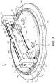
Figure 1 shows a perspective view of a first embodiment of a check valve in accordance with this disclosure; -
Figure 2 shows a perspective view of a first embodiment of the check valve ofFigure 1 with the flappers partially open; -
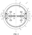
Figure 3 shows a plan view of the check valve ofFigure 1 ; -
Figure 4 shows a perspective view of second embodiment of a check valve in accordance with this disclosure; -
Figure 5 shows a perspective view of the check valve ofFigure 4 with the flappers partially open; -
Figure 6 shows a plan view of the check valve ofFigure 4 ; -
Figure 7 shows a sectional view of the check valve ofFigure 4 , along line A-A ofFigure 6 ; -
Figure 8 shows another sectional view of the check valve ofFigure 4 along line B-B ofFigure 6 ; -
Figure 9 shows a perspective view of a primary flapper element of the check valve ofFigure 4 ; and -
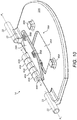
Figure 10 shows a perspective view of a flapper of the check valve ofFigure 4 . - With reference to
Figures 1 to 3 , a first embodiment ofcheck valve 2 in accordance with this disclosure is illustrated. - The
check valve 2 comprises avalve housing 4. Thevalve housing 4 is a generally planar annular element which in use may be mounted in a pipe, duct or the like. Thevalve housing 4 comprises a first generally D-shaped valve opening 6A and a second generally D-shaped valve opening 6B, which are separated by acentral web 8 of thevalve housing 4. - A pair of
mounts 10, such asmounting posts 10, extend upwardly from thevalve housing 4 on opposed sides of thevalve openings mounting posts 10 may, as shown, be separately formed from the valve housing and mounted thereto by suitable means, for example by bolts orother fasteners 12. Alternatively, in some embodiments, themounting posts 10 may be integrally formed, for example cast, with thevalve housing 4. In some embodiments and as discussed further below, more than onemounting post 10 may be provided on each side of thevalve openings - The valve openings 6 are respectively closed by a
first flapper 14 and asecond flapper 16. The first andsecond flappers sides lower surface flapper valve 2 is closed. In the illustrated embodiment eachflapper flappers Figures 4 to 10 ). - The
first flapper 14 is pivotably mounted around a first axis X1 for rotation relative to thevalve housing 4 and thesecond flapper 16 is pivotably mounted around a second axis X2 for rotation relative to thevalve housing 4. The first and second axes X1, X2 extend across the check valve housing and through the mountingposts 10 at the base of each mountingpost 10 as shown. The first and second axes X1, X2 are spaced laterally a distance D from one another, and arranged generally parallel to one another. Thecheck valve 2 andflappers flappers flappers check valve 2 andflappers - The first and
second flappers Figure 2 , in which they permit fluid flow F through first andsecond valve openings Figures 1 and3 , in which they prevent fluid flow through the first andsecond valve openings Figure 2 shows thevalve 2 in a partially open position. Theflappers flappers stop element 30, described later). - Each of the first and
second flappers posts 10 viarespective flapper spindles first flapper spindles 22 are attached tofirst flapper 14 at opposed ends of thebase 26A of thefirst flapper 14, onopposed sides first flapper 14. Twosecond flapper spindles 24 are attached to thesecond flapper 16 at opposed ends of the base 26B of thesecond flapper 16, onopposed sides second flapper 16. The flapper spindles 22, 24 extend outwardly fromlugs 23 upstanding from an upper surface of the flapper element. The flapper spindles 22, 24 are integral with thelugs 23 in this embodiment; however, in alternative arrangements, theflapper spindles lugs 23. As can be seen, thelugs 23 do not extend across the entire width of the flapper elements, and extend only a limited amount inwardly from an edge of eachflapper lugs 23 need only be long enough to provide a suitable support for theflapper spindles - One
first flapper spindle 22 and onesecond flapper spindle 24 is mounted to each mountingpost 10. - The mounting posts 10 may each include a pair of
bores 28 for receiving therespective flapper spindles - Alternatively, in a different arrangement (not illustrated) additional mounting posts may be provided on either side of the
valve openings flapper spindle valve openings flapper spindles - As illustrated in this embodiment, the
flapper spindles flappers bores 28 of the mounting posts 10. Alternatively theflapper spindles flappers flapper spindles flapper spindles - The
valve 2 may comprise astop element 30, such as astop pin 30, extending across thevalve housing 4 between the mounting posts 10. Eachstop pin 30 may be provided with a mountingportion 31 received in arespective bore 31A in the mountingpost 10. Thestop element 30 may be cylindrical, or have any other geometry, such as the more complex geometry shown in the illustrated embodiment. In the open position, theflappers stop element 30. Theflappers stop element 30 such that theflappers flappers stop pin 30 comprises a pair ofresilient tongue portions 30A extending transversely from acentral portion 30B.Bumpers 46 provided on theflappers tongue portions 30A in the open position. - In the illustrated embodiment of
Figures 4 to 10 , eachflapper primary flapper element secondary flapper element Figures 1 to 3 apply to the embodiment ofFigures 4 to 10 . - As seen in
Figure 4 , and also inFigures 5 to 8 and10 , theflapper spindles first flapper elements secondary flapper elements - Each
primary flapper element Figure 9 . It is noted that althoughFigures 9 and10 illustrate theflapper elements first flapper 14, similar arrangements may be used for thesecond flapper 16. - A
flapper opening central region primary flapper element flapper opening flapper opening flapper opening primary flapper element primary flapper element - Each
secondary flapper element - Each
secondary flapper element primary flapper element flapper opening first flapper 14 may be coaxial with the first axis X1 and the secondary flapper axis Y2 of thesecond flapper 16 may be coaxial with the second axis X2. The moment of inertia of rotating theprimary flapper elements secondary flapper elements valve 2. - Each of the primary and
secondary flapper elements lugs lugs primary flapper elements lugs pin lugs secondary flapper elements lugs primary flapper element lugs secondary flapper element lugs lugs lugs secondary flapper elements primary flapper element Figures 4 to 8 and10 . - Due to the spacing between the primary flapper lugs 23, the connection lugs 40A, 40B, 42A, 42B may easily be accommodated therebetween.
- The connecting lugs 40A, 40B, 42A, 42B may be cylindrical with a fillet at the point where they are attached to the primary or
secondary flapper elements lug respective pin - As the skilled person will appreciate, other arrangements of connecting
lugs flapper elements pins check valves 2 with limited space. - The
primary flapper elements primary flapper bumpers 46A and thesecondary flapper elements secondary flapper bumpers 46B - As in the earlier embodiment, a
stop pin 30 is provided between the mounting posts 10. Thisstop pin 30 is also formed with primary and secondaryresilient tongues secondary flapper bumpers - The
secondary flapper element primary flapper elements - When an opening pressure differential is applied to the
check valve 2 in an opening direction A, thesecondary flapper elements primary flapper elements secondary flapper elements primary flapper elements flapper openings primary flapper elements flapper openings primary flapper elements Figure 5 shows thecheck valve 2 with both theprimary flapper elements secondary flapper elements flapper elements stop element 30 such that they cannot rotate further. - The
secondary flapper elements stop element 30. In this position, theprimary flapper elements primary flapper elements secondary flapper elements - Referring to each of the embodiments, the
check valve 2 is assembled in a particular order. In the embodiment where theflapper spindles flappers flappers posts 10 by inserting thespindles posts 10 are attached to thevalve housing 4, for example byfasteners 12. - In the embodiment wherein the
flapper spindles flappers flappers posts 10 either before or after the mountingposts 10 are attached to thevalve housing 4, for example byfasteners 12. If theflappers posts 10 after the mountingposts 10 are attached to thevalve housing 4, the mountingposts 10 may be integrally formed with thevalve housing 4, for example by casting or additive manufacturing. - It will be appreciated that the above embodiments are exemplary only and that modifications may be made to the constructions illustrated without departing from the scope of the disclosure. For example, other forms of stop may be provided. In some embodiments, separate stops may be provided for the first and
second flappers stop 30 may be resilient (for example, as illustrated) or include dampers to reduce the impact of theflappers - The various embodiments described, by having separate axes of rotation X1, X2 for the first and
second flappers flapper stop 30. This reduces the possibility of damage to theflappers - Also, since the
flappers posts 10 viaspindles flappers flappers stop 30 may also reduce impact forces and thereby damage to theflappers
Claims (15)
- A check valve (2) comprising:a valve housing (4) defining a first valve opening (6A) and a second valve opening (6B);a first flapper (14) pivotably mounted around a first axis (X1) for rotation relative to the housing (4) between an open position in which it permits fluid flow (F) through the first valve opening (6A) and a closed position in which it prevents fluid flow (F) through the first valve opening (6A); anda second flapper (16) pivotably mounted around a second axis (X2) for rotation relative to the housing (4) between an open position in which it permits fluid flow (F) through the second valve opening (6B) and a closed position in which it prevents fluid flow (F) through the second valve opening (6B), wherein the first axis (X1) is spaced laterally from to the second axis (X2).
- The check valve of claim 1, wherein the first axis (X1) is generally parallel to the second axis (X2).
- The check valve of claim 1 or 2, further comprising a stop element (30) arranged such that the flappers (14, 16) will contact the stop element (30) in their open positions.
- The check valve of any preceding claim, wherein:
the housing (4) comprises a pair of opposed mounts (10), the first and second flappers (14, 16) are pivotably mounted between the mounts (10) by means of respective flapper spindles (22, 24). - The check valve of claim 4, wherein:
each of the mounts (10) comprises a mounting post (10). - The check valve of claim 4 or 5, wherein:each of the first and second mounts (10) comprises a bore (28); andeach of the flapper spindles (22, 24) is received within a respective bore (28).
- The check valve of claim 6, wherein:
each flapper spindle (22, 24) is formed integrally with a respective flapper (14,16). - The check valve of claim 6, wherein each flapper spindle (22, 24) is formed separately from a respective flapper (14, 16) and mounted thereto.
- The check valve of claim 6 wherein each flapper spindle (22, 24) is formed separately from a respective flapper (14, 16) and a respective mount (10) and received in respective bores (28) therein.
- The check valve of any preceding claim, wherein:the first flapper (14) is symmetrical about an axis (Y) transverse to the first axis (X1); andthe second flapper (16) is symmetrical about an axis (Y) transverse to the second axis (X2).
- The check valve of any preceding claim, wherein:each flapper (14,16) comprises a primary flapper element (32A, 32B) and at least one secondary flapper element (34A, 34B);the primary flapper element (32A, 32B) further comprises at least one flapper opening (36A, 36B) formed therethrough; andthe at least one secondary flapper element (34A, 34B) is pivotally mounted about a secondary flapper axis (Y1, Y2) such that it may rotate relative to the primary flapper element (32, 32B) for opening and closing the at least one flapper opening (36A, 36B) in the primary flapper element (32A, 32B).
- The check valve of claim 11, wherein the secondary flapper axis (Y1) of the first flapper (14) is coaxial with the first axis (X1) and the secondary flapper axis (Y2) of the second flapper (16) is coaxial with the second axis (X2).
- The check valve of claim 11 or 12, wherein:each of the primary flapper elements (32A, 32B) and the each of secondary flapper elements (34A, 34B) comprise at least one connecting lug (40A, 40B, 42A, 42B); andthe valve (2) further comprises a pair of connecting pins (44A, 44B) configured to be rotatably received in the connecting lugs (40A, 40B, 42A, 42B) of each flapper (14, 16) for mounting the secondary flapper elements (34A, 34B) to the primary flapper elements (32A, 32B).
- A flapper (14, 16) for a check valve (2) comprising:a flapper portion with first and second opposed sides (14A, 14B; 16A, 16B); anda pair of coaxial flapper mounting spindles (22; 24) formed integrally with the flapper portion and projecting from and beyond the opposed sides (14A, 14B; 16A, 16B) of the flapper portion.
- A method of making the check valve (2) of claim 4 or any of claims 5 to 13 as dependent on claim 4, comprising:mounting the first and second flappers (14, 16) on the pair of opposed mounts (10); thenattaching the pair of opposed mounts (10) to the valve housing (4).
Priority Applications (2)
| Application Number | Priority Date | Filing Date | Title |
|---|---|---|---|
| EP18461641.5A EP3667138B1 (en) | 2018-12-10 | 2018-12-10 | Check valve |
| US16/707,166 US11112023B2 (en) | 2018-12-10 | 2019-12-09 | Check valve |
Applications Claiming Priority (1)
| Application Number | Priority Date | Filing Date | Title |
|---|---|---|---|
| EP18461641.5A EP3667138B1 (en) | 2018-12-10 | 2018-12-10 | Check valve |
Publications (2)
| Publication Number | Publication Date |
|---|---|
| EP3667138A1 true EP3667138A1 (en) | 2020-06-17 |
| EP3667138B1 EP3667138B1 (en) | 2022-11-23 |
Family
ID=64665101
Family Applications (1)
| Application Number | Title | Priority Date | Filing Date |
|---|---|---|---|
| EP18461641.5A Active EP3667138B1 (en) | 2018-12-10 | 2018-12-10 | Check valve |
Country Status (2)
| Country | Link |
|---|---|
| US (1) | US11112023B2 (en) |
| EP (1) | EP3667138B1 (en) |
Families Citing this family (2)
| Publication number | Priority date | Publication date | Assignee | Title |
|---|---|---|---|---|
| EP4083478B1 (en) * | 2021-04-27 | 2024-09-18 | UTC Aerospace Systems Wroclaw Sp. z o.o. | Flapper check valve |
| US12264668B2 (en) | 2023-06-30 | 2025-04-01 | Hamilton Sundstrand Corporation | Flapper valve with common rotational direction |
Citations (6)
| Publication number | Priority date | Publication date | Assignee | Title |
|---|---|---|---|---|
| GB1187882A (en) * | 1968-04-30 | 1970-04-15 | William John Woolley | Check Valves. |
| DE2718821B1 (en) * | 1977-04-28 | 1978-06-22 | Gerdts Gustav F Kg | Check valve |
| GB2096281A (en) * | 1981-04-07 | 1982-10-13 | Gerdts Gustav F Gmbh Co Kg | Non-return valve |
| JPS58157074U (en) * | 1982-04-15 | 1983-10-20 | 株式会社荏原製作所 | swing type check valve |
| EP3193059A1 (en) * | 2016-01-15 | 2017-07-19 | Hamilton Sundstrand Corporation | Check valve |
| EP3318786A1 (en) * | 2016-11-08 | 2018-05-09 | Hamilton Sundstrand Corporation | Check valve |
Family Cites Families (9)
| Publication number | Priority date | Publication date | Assignee | Title |
|---|---|---|---|---|
| US1673831A (en) * | 1925-04-29 | 1928-06-19 | Oscar C Kuehne | Valve |
| US3384112A (en) * | 1965-12-15 | 1968-05-21 | John W Woolley | Island check valve |
| DE3206597C2 (en) | 1982-02-24 | 1985-04-11 | Siemens AG, 1000 Berlin und 8000 München | Connection distributor |
| US4781212A (en) * | 1987-05-13 | 1988-11-01 | Scaramucci John P | Swing check valve with removable cage and disc |
| US5056548A (en) * | 1990-10-12 | 1991-10-15 | Kf Industries, Inc. | Check valve assembly with removable seat |
| US6796327B2 (en) * | 2001-11-09 | 2004-09-28 | Bnl Industries, Inc. | Check valve with multiple doors |
| WO2013011348A1 (en) * | 2011-07-20 | 2013-01-24 | Hawa Valves (India) Private Limited | Dual plate check valve |
| EP3193055B1 (en) * | 2016-01-15 | 2020-05-06 | Hamilton Sundstrand Corporation | Check valve |
| EP3418611B1 (en) * | 2017-06-21 | 2020-04-22 | Hamilton Sundstrand Corporation | Check valves |
-
2018
- 2018-12-10 EP EP18461641.5A patent/EP3667138B1/en active Active
-
2019
- 2019-12-09 US US16/707,166 patent/US11112023B2/en active Active
Patent Citations (7)
| Publication number | Priority date | Publication date | Assignee | Title |
|---|---|---|---|---|
| GB1187882A (en) * | 1968-04-30 | 1970-04-15 | William John Woolley | Check Valves. |
| DE2718821B1 (en) * | 1977-04-28 | 1978-06-22 | Gerdts Gustav F Kg | Check valve |
| GB2096281A (en) * | 1981-04-07 | 1982-10-13 | Gerdts Gustav F Gmbh Co Kg | Non-return valve |
| JPS58157074U (en) * | 1982-04-15 | 1983-10-20 | 株式会社荏原製作所 | swing type check valve |
| EP3193059A1 (en) * | 2016-01-15 | 2017-07-19 | Hamilton Sundstrand Corporation | Check valve |
| US10088065B2 (en) | 2016-01-15 | 2018-10-02 | Hamilton Sundstrand Corporation | Check valves and flapper arrangements therefor |
| EP3318786A1 (en) * | 2016-11-08 | 2018-05-09 | Hamilton Sundstrand Corporation | Check valve |
Also Published As
| Publication number | Publication date |
|---|---|
| EP3667138B1 (en) | 2022-11-23 |
| US20200182368A1 (en) | 2020-06-11 |
| US11112023B2 (en) | 2021-09-07 |
Similar Documents
| Publication | Publication Date | Title |
|---|---|---|
| EP3193059B1 (en) | Check valve | |
| US11112023B2 (en) | Check valve | |
| JP3689912B2 (en) | Check valve for fluid | |
| JP2686999B2 (en) | Sealing member for valve | |
| EP3181969B1 (en) | Check valve | |
| EP3181964B1 (en) | Check valve | |
| US9835261B2 (en) | Check valves | |
| EP3660366B1 (en) | Check valves | |
| EP3220024B1 (en) | Check valve | |
| EP3258147B1 (en) | Check valves | |
| US5501192A (en) | Air valve for the intake manifold of an internal combustion engine | |
| US5333838A (en) | Blade damper with extensions to reduce boundary leakage | |
| JPS608379B2 (en) | valve | |
| US10648581B2 (en) | Check valves | |
| EP3193054B1 (en) | Check valves | |
| US4209037A (en) | Environmental check valve | |
| EP3418611B1 (en) | Check valves | |
| EP3508765B1 (en) | Check valves | |
| US20190359343A1 (en) | Aircraft comprising at least one cowling equipped with an improved hinge system | |
| EP3495703B1 (en) | Check valves | |
| EP4083478B1 (en) | Flapper check valve | |
| JP2006233907A (en) | Intake control device | |
| KR101932155B1 (en) | A cabinet | |
| KR20060052646A (en) | Butterfly Valve for Gas Pressure Control | |
| GB2538558A (en) | Improved butterfly valve |
Legal Events
| Date | Code | Title | Description |
|---|---|---|---|
| PUAI | Public reference made under article 153(3) epc to a published international application that has entered the european phase |
Free format text: ORIGINAL CODE: 0009012 |
|
| STAA | Information on the status of an ep patent application or granted ep patent |
Free format text: STATUS: THE APPLICATION HAS BEEN PUBLISHED |
|
| AK | Designated contracting states |
Kind code of ref document: A1 Designated state(s): AL AT BE BG CH CY CZ DE DK EE ES FI FR GB GR HR HU IE IS IT LI LT LU LV MC MK MT NL NO PL PT RO RS SE SI SK SM TR |
|
| AX | Request for extension of the european patent |
Extension state: BA ME |
|
| STAA | Information on the status of an ep patent application or granted ep patent |
Free format text: STATUS: REQUEST FOR EXAMINATION WAS MADE |
|
| 17P | Request for examination filed |
Effective date: 20201216 |
|
| RBV | Designated contracting states (corrected) |
Designated state(s): AL AT BE BG CH CY CZ DE DK EE ES FI FR GB GR HR HU IE IS IT LI LT LU LV MC MK MT NL NO PL PT RO RS SE SI SK SM TR |
|
| RAP3 | Party data changed (applicant data changed or rights of an application transferred) |
Owner name: HAMILTON SUNDSTRAND CORPORATION |
|
| STAA | Information on the status of an ep patent application or granted ep patent |
Free format text: STATUS: EXAMINATION IS IN PROGRESS |
|
| 17Q | First examination report despatched |
Effective date: 20210615 |
|
| GRAP | Despatch of communication of intention to grant a patent |
Free format text: ORIGINAL CODE: EPIDOSNIGR1 |
|
| STAA | Information on the status of an ep patent application or granted ep patent |
Free format text: STATUS: GRANT OF PATENT IS INTENDED |
|
| INTG | Intention to grant announced |
Effective date: 20211215 |
|
| GRAJ | Information related to disapproval of communication of intention to grant by the applicant or resumption of examination proceedings by the epo deleted |
Free format text: ORIGINAL CODE: EPIDOSDIGR1 |
|
| STAA | Information on the status of an ep patent application or granted ep patent |
Free format text: STATUS: EXAMINATION IS IN PROGRESS |
|
| INTC | Intention to grant announced (deleted) | ||
| GRAP | Despatch of communication of intention to grant a patent |
Free format text: ORIGINAL CODE: EPIDOSNIGR1 |
|
| STAA | Information on the status of an ep patent application or granted ep patent |
Free format text: STATUS: GRANT OF PATENT IS INTENDED |
|
| INTG | Intention to grant announced |
Effective date: 20220607 |
|
| GRAS | Grant fee paid |
Free format text: ORIGINAL CODE: EPIDOSNIGR3 |
|
| GRAA | (expected) grant |
Free format text: ORIGINAL CODE: 0009210 |
|
| STAA | Information on the status of an ep patent application or granted ep patent |
Free format text: STATUS: THE PATENT HAS BEEN GRANTED |
|
| AK | Designated contracting states |
Kind code of ref document: B1 Designated state(s): AL AT BE BG CH CY CZ DE DK EE ES FI FR GB GR HR HU IE IS IT LI LT LU LV MC MK MT NL NO PL PT RO RS SE SI SK SM TR |
|
| REG | Reference to a national code |
Ref country code: GB Ref legal event code: FG4D |
|
| REG | Reference to a national code |
Ref country code: CH Ref legal event code: EP |
|
| REG | Reference to a national code |
Ref country code: AT Ref legal event code: REF Ref document number: 1533312 Country of ref document: AT Kind code of ref document: T Effective date: 20221215 Ref country code: DE Ref legal event code: R096 Ref document number: 602018043328 Country of ref document: DE |
|
| REG | Reference to a national code |
Ref country code: IE Ref legal event code: FG4D |
|
| REG | Reference to a national code |
Ref country code: LT Ref legal event code: MG9D |
|
| REG | Reference to a national code |
Ref country code: NL Ref legal event code: MP Effective date: 20221123 |
|
| REG | Reference to a national code |
Ref country code: AT Ref legal event code: MK05 Ref document number: 1533312 Country of ref document: AT Kind code of ref document: T Effective date: 20221123 |
|
| PG25 | Lapsed in a contracting state [announced via postgrant information from national office to epo] |
Ref country code: SE Free format text: LAPSE BECAUSE OF FAILURE TO SUBMIT A TRANSLATION OF THE DESCRIPTION OR TO PAY THE FEE WITHIN THE PRESCRIBED TIME-LIMIT Effective date: 20221123 Ref country code: PT Free format text: LAPSE BECAUSE OF FAILURE TO SUBMIT A TRANSLATION OF THE DESCRIPTION OR TO PAY THE FEE WITHIN THE PRESCRIBED TIME-LIMIT Effective date: 20230323 Ref country code: NO Free format text: LAPSE BECAUSE OF FAILURE TO SUBMIT A TRANSLATION OF THE DESCRIPTION OR TO PAY THE FEE WITHIN THE PRESCRIBED TIME-LIMIT Effective date: 20230223 Ref country code: LT Free format text: LAPSE BECAUSE OF FAILURE TO SUBMIT A TRANSLATION OF THE DESCRIPTION OR TO PAY THE FEE WITHIN THE PRESCRIBED TIME-LIMIT Effective date: 20221123 Ref country code: FI Free format text: LAPSE BECAUSE OF FAILURE TO SUBMIT A TRANSLATION OF THE DESCRIPTION OR TO PAY THE FEE WITHIN THE PRESCRIBED TIME-LIMIT Effective date: 20221123 Ref country code: ES Free format text: LAPSE BECAUSE OF FAILURE TO SUBMIT A TRANSLATION OF THE DESCRIPTION OR TO PAY THE FEE WITHIN THE PRESCRIBED TIME-LIMIT Effective date: 20221123 Ref country code: AT Free format text: LAPSE BECAUSE OF FAILURE TO SUBMIT A TRANSLATION OF THE DESCRIPTION OR TO PAY THE FEE WITHIN THE PRESCRIBED TIME-LIMIT Effective date: 20221123 |
|
| PG25 | Lapsed in a contracting state [announced via postgrant information from national office to epo] |
Ref country code: RS Free format text: LAPSE BECAUSE OF FAILURE TO SUBMIT A TRANSLATION OF THE DESCRIPTION OR TO PAY THE FEE WITHIN THE PRESCRIBED TIME-LIMIT Effective date: 20221123 Ref country code: PL Free format text: LAPSE BECAUSE OF FAILURE TO SUBMIT A TRANSLATION OF THE DESCRIPTION OR TO PAY THE FEE WITHIN THE PRESCRIBED TIME-LIMIT Effective date: 20221123 Ref country code: LV Free format text: LAPSE BECAUSE OF FAILURE TO SUBMIT A TRANSLATION OF THE DESCRIPTION OR TO PAY THE FEE WITHIN THE PRESCRIBED TIME-LIMIT Effective date: 20221123 Ref country code: IS Free format text: LAPSE BECAUSE OF FAILURE TO SUBMIT A TRANSLATION OF THE DESCRIPTION OR TO PAY THE FEE WITHIN THE PRESCRIBED TIME-LIMIT Effective date: 20230323 Ref country code: HR Free format text: LAPSE BECAUSE OF FAILURE TO SUBMIT A TRANSLATION OF THE DESCRIPTION OR TO PAY THE FEE WITHIN THE PRESCRIBED TIME-LIMIT Effective date: 20221123 Ref country code: GR Free format text: LAPSE BECAUSE OF FAILURE TO SUBMIT A TRANSLATION OF THE DESCRIPTION OR TO PAY THE FEE WITHIN THE PRESCRIBED TIME-LIMIT Effective date: 20230224 |
|
| P01 | Opt-out of the competence of the unified patent court (upc) registered |
Effective date: 20230522 |
|
| PG25 | Lapsed in a contracting state [announced via postgrant information from national office to epo] |
Ref country code: NL Free format text: LAPSE BECAUSE OF FAILURE TO SUBMIT A TRANSLATION OF THE DESCRIPTION OR TO PAY THE FEE WITHIN THE PRESCRIBED TIME-LIMIT Effective date: 20221123 |
|
| PG25 | Lapsed in a contracting state [announced via postgrant information from national office to epo] |
Ref country code: SM Free format text: LAPSE BECAUSE OF FAILURE TO SUBMIT A TRANSLATION OF THE DESCRIPTION OR TO PAY THE FEE WITHIN THE PRESCRIBED TIME-LIMIT Effective date: 20221123 Ref country code: RO Free format text: LAPSE BECAUSE OF FAILURE TO SUBMIT A TRANSLATION OF THE DESCRIPTION OR TO PAY THE FEE WITHIN THE PRESCRIBED TIME-LIMIT Effective date: 20221123 Ref country code: EE Free format text: LAPSE BECAUSE OF FAILURE TO SUBMIT A TRANSLATION OF THE DESCRIPTION OR TO PAY THE FEE WITHIN THE PRESCRIBED TIME-LIMIT Effective date: 20221123 Ref country code: DK Free format text: LAPSE BECAUSE OF FAILURE TO SUBMIT A TRANSLATION OF THE DESCRIPTION OR TO PAY THE FEE WITHIN THE PRESCRIBED TIME-LIMIT Effective date: 20221123 Ref country code: CZ Free format text: LAPSE BECAUSE OF FAILURE TO SUBMIT A TRANSLATION OF THE DESCRIPTION OR TO PAY THE FEE WITHIN THE PRESCRIBED TIME-LIMIT Effective date: 20221123 |
|
| REG | Reference to a national code |
Ref country code: CH Ref legal event code: PL |
|
| REG | Reference to a national code |
Ref country code: DE Ref legal event code: R097 Ref document number: 602018043328 Country of ref document: DE Ref country code: BE Ref legal event code: MM Effective date: 20221231 |
|
| PG25 | Lapsed in a contracting state [announced via postgrant information from national office to epo] |
Ref country code: SK Free format text: LAPSE BECAUSE OF FAILURE TO SUBMIT A TRANSLATION OF THE DESCRIPTION OR TO PAY THE FEE WITHIN THE PRESCRIBED TIME-LIMIT Effective date: 20221123 Ref country code: LU Free format text: LAPSE BECAUSE OF NON-PAYMENT OF DUE FEES Effective date: 20221210 Ref country code: AL Free format text: LAPSE BECAUSE OF FAILURE TO SUBMIT A TRANSLATION OF THE DESCRIPTION OR TO PAY THE FEE WITHIN THE PRESCRIBED TIME-LIMIT Effective date: 20221123 |
|
| PLBE | No opposition filed within time limit |
Free format text: ORIGINAL CODE: 0009261 |
|
| STAA | Information on the status of an ep patent application or granted ep patent |
Free format text: STATUS: NO OPPOSITION FILED WITHIN TIME LIMIT |
|
| PG25 | Lapsed in a contracting state [announced via postgrant information from national office to epo] |
Ref country code: LI Free format text: LAPSE BECAUSE OF NON-PAYMENT OF DUE FEES Effective date: 20221231 Ref country code: IE Free format text: LAPSE BECAUSE OF NON-PAYMENT OF DUE FEES Effective date: 20221210 Ref country code: CH Free format text: LAPSE BECAUSE OF NON-PAYMENT OF DUE FEES Effective date: 20221231 |
|
| 26N | No opposition filed |
Effective date: 20230824 |
|
| PG25 | Lapsed in a contracting state [announced via postgrant information from national office to epo] |
Ref country code: SI Free format text: LAPSE BECAUSE OF FAILURE TO SUBMIT A TRANSLATION OF THE DESCRIPTION OR TO PAY THE FEE WITHIN THE PRESCRIBED TIME-LIMIT Effective date: 20221123 Ref country code: BE Free format text: LAPSE BECAUSE OF NON-PAYMENT OF DUE FEES Effective date: 20221231 |
|
| PG25 | Lapsed in a contracting state [announced via postgrant information from national office to epo] |
Ref country code: HU Free format text: LAPSE BECAUSE OF FAILURE TO SUBMIT A TRANSLATION OF THE DESCRIPTION OR TO PAY THE FEE WITHIN THE PRESCRIBED TIME-LIMIT; INVALID AB INITIO Effective date: 20181210 |
|
| PG25 | Lapsed in a contracting state [announced via postgrant information from national office to epo] |
Ref country code: CY Free format text: LAPSE BECAUSE OF FAILURE TO SUBMIT A TRANSLATION OF THE DESCRIPTION OR TO PAY THE FEE WITHIN THE PRESCRIBED TIME-LIMIT Effective date: 20221123 |
|
| PG25 | Lapsed in a contracting state [announced via postgrant information from national office to epo] |
Ref country code: MK Free format text: LAPSE BECAUSE OF FAILURE TO SUBMIT A TRANSLATION OF THE DESCRIPTION OR TO PAY THE FEE WITHIN THE PRESCRIBED TIME-LIMIT Effective date: 20221123 Ref country code: IT Free format text: LAPSE BECAUSE OF FAILURE TO SUBMIT A TRANSLATION OF THE DESCRIPTION OR TO PAY THE FEE WITHIN THE PRESCRIBED TIME-LIMIT Effective date: 20221123 |
|
| PG25 | Lapsed in a contracting state [announced via postgrant information from national office to epo] |
Ref country code: MC Free format text: LAPSE BECAUSE OF FAILURE TO SUBMIT A TRANSLATION OF THE DESCRIPTION OR TO PAY THE FEE WITHIN THE PRESCRIBED TIME-LIMIT Effective date: 20221123 |
|
| PG25 | Lapsed in a contracting state [announced via postgrant information from national office to epo] |
Ref country code: TR Free format text: LAPSE BECAUSE OF FAILURE TO SUBMIT A TRANSLATION OF THE DESCRIPTION OR TO PAY THE FEE WITHIN THE PRESCRIBED TIME-LIMIT Effective date: 20221123 Ref country code: MC Free format text: LAPSE BECAUSE OF FAILURE TO SUBMIT A TRANSLATION OF THE DESCRIPTION OR TO PAY THE FEE WITHIN THE PRESCRIBED TIME-LIMIT Effective date: 20221123 |
|
| PG25 | Lapsed in a contracting state [announced via postgrant information from national office to epo] |
Ref country code: BG Free format text: LAPSE BECAUSE OF FAILURE TO SUBMIT A TRANSLATION OF THE DESCRIPTION OR TO PAY THE FEE WITHIN THE PRESCRIBED TIME-LIMIT Effective date: 20221123 |
|
| PG25 | Lapsed in a contracting state [announced via postgrant information from national office to epo] |
Ref country code: MT Free format text: LAPSE BECAUSE OF FAILURE TO SUBMIT A TRANSLATION OF THE DESCRIPTION OR TO PAY THE FEE WITHIN THE PRESCRIBED TIME-LIMIT Effective date: 20221123 |
|
| PGFP | Annual fee paid to national office [announced via postgrant information from national office to epo] |
Ref country code: DE Payment date: 20251126 Year of fee payment: 8 |
|
| PGFP | Annual fee paid to national office [announced via postgrant information from national office to epo] |
Ref country code: GB Payment date: 20251119 Year of fee payment: 8 |
|
| PGFP | Annual fee paid to national office [announced via postgrant information from national office to epo] |
Ref country code: FR Payment date: 20251119 Year of fee payment: 8 |