EP3667117A1 - Strut mount - Google Patents
Strut mount Download PDFInfo
- Publication number
- EP3667117A1 EP3667117A1 EP18845016.7A EP18845016A EP3667117A1 EP 3667117 A1 EP3667117 A1 EP 3667117A1 EP 18845016 A EP18845016 A EP 18845016A EP 3667117 A1 EP3667117 A1 EP 3667117A1
- Authority
- EP
- European Patent Office
- Prior art keywords
- main body
- strut
- projection
- rubber
- contact
- Prior art date
- Legal status (The legal status is an assumption and is not a legal conclusion. Google has not performed a legal analysis and makes no representation as to the accuracy of the status listed.)
- Withdrawn
Links
Images

Classifications
-
- B—PERFORMING OPERATIONS; TRANSPORTING
- B60—VEHICLES IN GENERAL
- B60G—VEHICLE SUSPENSION ARRANGEMENTS
- B60G13/00—Resilient suspensions characterised by arrangement, location or type of vibration dampers
- B60G13/001—Arrangements for attachment of dampers
- B60G13/003—Arrangements for attachment of dampers characterised by the mounting on the vehicle body or chassis of the damper unit
-
- F—MECHANICAL ENGINEERING; LIGHTING; HEATING; WEAPONS; BLASTING
- F16—ENGINEERING ELEMENTS AND UNITS; GENERAL MEASURES FOR PRODUCING AND MAINTAINING EFFECTIVE FUNCTIONING OF MACHINES OR INSTALLATIONS; THERMAL INSULATION IN GENERAL
- F16F—SPRINGS; SHOCK-ABSORBERS; MEANS FOR DAMPING VIBRATION
- F16F9/00—Springs, vibration-dampers, shock-absorbers, or similarly-constructed movement-dampers using a fluid or the equivalent as damping medium
- F16F9/32—Details
- F16F9/54—Arrangements for attachment
-
- B—PERFORMING OPERATIONS; TRANSPORTING
- B60—VEHICLES IN GENERAL
- B60G—VEHICLE SUSPENSION ARRANGEMENTS
- B60G15/00—Resilient suspensions characterised by arrangement, location or type of combined spring and vibration damper, e.g. telescopic type
- B60G15/02—Resilient suspensions characterised by arrangement, location or type of combined spring and vibration damper, e.g. telescopic type having mechanical spring
- B60G15/06—Resilient suspensions characterised by arrangement, location or type of combined spring and vibration damper, e.g. telescopic type having mechanical spring and fluid damper
-
- B—PERFORMING OPERATIONS; TRANSPORTING
- B60—VEHICLES IN GENERAL
- B60G—VEHICLE SUSPENSION ARRANGEMENTS
- B60G2204/00—Indexing codes related to suspensions per se or to auxiliary parts
- B60G2204/10—Mounting of suspension elements
- B60G2204/12—Mounting of springs or dampers
- B60G2204/128—Damper mount on vehicle body or chassis
-
- B—PERFORMING OPERATIONS; TRANSPORTING
- B60—VEHICLES IN GENERAL
- B60G—VEHICLE SUSPENSION ARRANGEMENTS
- B60G2204/00—Indexing codes related to suspensions per se or to auxiliary parts
- B60G2204/40—Auxiliary suspension parts; Adjustment of suspensions
- B60G2204/41—Elastic mounts, e.g. bushings
-
- B—PERFORMING OPERATIONS; TRANSPORTING
- B60—VEHICLES IN GENERAL
- B60G—VEHICLE SUSPENSION ARRANGEMENTS
- B60G2204/00—Indexing codes related to suspensions per se or to auxiliary parts
- B60G2204/40—Auxiliary suspension parts; Adjustment of suspensions
- B60G2204/45—Stops limiting travel
Definitions
- This disclosure relates to a strut mount.
- a conventionally known structure for attaching a strut rod to a vehicle body side panel has a vehicle body side panel having a depression, a cylindrical body that has a tapered portion whose diameter increases as it goes downward and that is attached to the strut rod, and a cylindrical rubber body that is fixed to the outer peripheral surface of the cylindrical body and that has a mating junction mated with the depression (see JP 2014-74481 A (PTL 1)).
- a strut mount is disposed between the strut rod and the vehicle body side panel by mating the mating junction of the rubber body with the depression of the vehicle body side panel.
- the conventional strut mount has a structure in which a cylindrical body formed of, for example, a steel plate is included, a rubber body is fixed over the entire circumference of the outer peripheral surface of the cylindrical body, and a part of the rubber body is also fixed to the inner peripheral surface thereof.
- the conventional strut mount has a structure in which a cylindrical body is embedded inside a rubber body by, for example, insert molding.
- the rubber body is provided with a rubber projection on the upper extension of the cylindrical body, and the rubber projection is in close contact with a rebound stopper metal fitting that is fixed to the tip end side of the strut rod.
- the strut rod, tightening nut or the like may rust. When rusting occurs, the tightening nut may be loosened or broken, for example.
- the rubber projection is integrally connected to the rubber body, so that the rubber projection fluctuates in conjunction with the main body rubber.
- the strut mount of the present disclosure is a strut mount that attaches and supports a tip end of a strut rod of a strut suspension provided on a vehicle to a vehicle body side panel of the vehicle, where the strut mount includes a cylindrical body attached to the strut rod, and a cylindrical main body rubber that is fixed to an outer peripheral surface of the cylindrical body and is in contact with the vehicle body side panel; the main body rubber is provided with a projection extending in an axial direction of the strut rod, where the projection is separated from a main body of the main body rubber by a concave portion, and is connected to the main body by a connecting portion that serves as a bottom of the concave portion; and a minimum thickness of the connecting portion is smaller than a radial thickness of the projection.
- a strut mount where a rubber projection for preventing water, dust or the like from entering the inner diameter side of a main body rubber is included and the rubber projection does not fluctuate in conjunction with the main body rubber.
- the strut mount 10 of the present embodiment is used to attach and support a tip end of a strut rod S of a strut suspension provided in a vehicle such as an automobile (not illustrated in the drawings), that is, a tip end of a piston rod of a shock absorber constituting the strut suspension, to a vehicle body side panel P constituting the vehicle.
- the strut mount 10 of the present embodiment includes a cylindrical body 11 attached to the strut rod S of the strut suspension, and a cylindrical main body rubber 12 that is fixed to the outer peripheral surface of the cylindrical body 11 and is in contact with the vehicle body side panel P, where the main body rubber 12 is provided with a projection (rubber projection) 15 extending in the axial direction of the strut rod S, the projection 15 is separated from a main body 13 of the main body rubber 12 by a concave portion 12a and is connected to the main body 13 by a connecting portion 14 which is the bottom of the concave portion 12a, and the minimum thickness a of the connecting portion 14 is smaller than the radial thickness b of the projection 15.
- a rebound stopper metal fitting R is attached to the tip end side of the strut rod S to which the cylindrical body 11 is attached, where the rebound stopper metal fitting R is at a distance above the cylindrical body 11 (see FIG. 1 ).
- the rebound stopper metal fitting R is formed in a substantially disk-like shape by, for example, a metal material, has a central axis opening Ra and a concave portion Rb that is one step down from the peripheral portion at the central portion around the central axis opening Ra, and is fixed to the strut rod S that passes through the central axis opening Ra.
- the cylindrical body 11 of the present embodiment is formed in a substantially disk-like shape by, for example, a metal material, has a central axis opening 11a and an outward flange-shaped peripheral portion 11b that is one step down from the central portion, and is fixed to the strut rod S that passes through the central axis opening 11a.
- the main body rubber 12 of the present embodiment is located concentrically with a central axis space 12b through which the strut rod S passes.
- the main body rubber 12 has a main body 13 and a projection 15 with a groove-like concave portion 12a opening to an upper surface 12c interposed therebetween.
- the main body rubber 12 is formed in a substantially cylindrical shape, where the diameter increases as it goes downward, and the outer peripheral surface is a downward inclined surface.
- the main body rubber 12 has a metal member 12d that is partially exposed to the outer peripheral surface and is embedded in the vicinity of the outer peripheral surface, such as a belt-shaped metal member extending over the entire outer peripheral surface (see FIG. 1 ).
- the substantially upper half portion of the main body rubber 12 in the up-down direction is formed as a mating junction, and the outer shape of the mating junction substantially matches the shape of a depression provided in the surrounding area of an opening Pa opened in the vehicle body side panel P, so that the mating junction can be integrally mated with the depression (see FIG. 1 ).
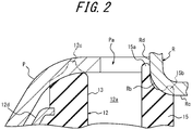
- the upper surface 12c of the main body rubber 12 is formed in a substantially chevron shape protruding upward where the radial width decreases as it goes upward (see FIG. 2 ).
- the inner peripheral surface of the main body 13 of the main body rubber 12 is integrally connected to the outer peripheral surface of the projection 15 via the connecting portion 14 (see FIG. 1 ), and the minimum thickness a of the connecting portion 14 is smaller than the radial thickness b of the projection 15.
- the minimum thickness a of the connecting portion 14 refers to the thickness in the up-down direction of the thinnest part of the connecting portion 14 in the present embodiment
- the radial thickness b of the projection 15 is the average thickness in the radial direction of the projection 15 in the present embodiment.
- the minimum thickness a of the connecting portion 14 is 4 mm or less, preferably 1.5 mm to 3 mm.
- the rubber thickness of the connecting portion of the main body rubber 12 to the projection 15 is the smallest in the whole main body rubber 12, In this way, it is possible to suppress the fluctuation generated in the main body rubber 12 from being transmitted to the projection 15 via the connecting portion 14.
- the minimum thickness a is 4 mm or less, it is possible to effectively suppress the fluctuation of the main body rubber 12 from being transmitted to the projection 15.
- the minimum thickness a is 1.5 mm to 3 mm, it is possible to more reliably suppress the transmitting of fluctuation.
- the projection 15 fluctuates as the main body rubber 12 fluctuates.
- this does not happen because the fluctuation generated in the main body rubber 12 is suppressed from being transmitted to the projection 15 via the connection portion. Therefore, the case where the projection 15 is pulled and falls and it is impossible to provide a close contact or a seal to the rebound stopper metal fitting R, for example, does not happen to the strut mount 10 of the present embodiment.
- the tip end of the projection 15 of the main body rubber 12 is in contact with a bent portion Rb of the rebound stopper metal fitting R attached to the strut rod S above the cylindrical body 11.
- This structure can suppress the projection 15 from falling inward.
- the bent portion Rb of the rebound stopper metal fitting R has a bottom surface Rc and a rising surface Rd that is bent at a substantially right angle and then rise following the bottom surface Rc (see FIG. 2 ).
- the projection 15 of the present embodiment extends in the axial direction of the strut rod S, so that the outer surface in the radial direction (outer peripheral surface) of the projection 15, which is continuous with the inner peripheral surface of the main body 13, is positioned radially outside the rising surface Rd of the rebound stopper metal fitting R (see FIGS. 1 and 2 ).
- the tip end of the projection 15 is formed in a bifurcated shape having a first contact portion 15a in contact with the rising surface Rd side of the bent portion Rb and a second contact portion 15b in contact with the bottom surface Rc side of the bent portion Rb.
- This structure can reliably suppress the projection 15 from falling inward.
- the first contact portion 15a of the present embodiment is formed in a ridge shape having substantially the same width in the radial direction and in the height direction so that the radially outside portion of the projection 15 is extended upward (see FIG. 2 ).
- the first contact portion 15a is positioned so as to cover the rising surface Rd side from the outside in the radial direction when the tip end of the projection 15 is in contact with the bent portion Rb of the rebound stopper metal fitting R, and the first contact portion 15a is in contact with the rising surface Rd side (see FIG. 2 ).
- the second contact portion 15b of the present embodiment is formed by protruding the radially inside portion of the projection 15 in a substantially chevron shape (see FIG. 2 ).
- the tip end of the projection 15 is in contact with the bent portion Rb of the rebound stopper metal fitting R, the second contact portion 15b is in contact with the bottom surface Rc side so that the second contact portion 15b is pressed and crushed against the bottom surface Rc side (see FIG. 2 ).
- the outer surface between the first contact portion 15a and the second contact portion 15b of the present embodiment is formed by a curved surface having a curvature smaller than the curvature of the outer surface of the bent portion Rb of the rebound stopper metal fitting R. That is, the curve drawn by the curved surface between the first contact portion 15a and the second contact portion 15b is steeper than the outer surface of the bent portion Rb (see FIGS. 1 and 2 ).
- This structure can closely adhere the projection 15 to the bent portion Rb and more reliably suppress the projection 15 from falling inward.
- the strut mount 10 of the present embodiment is used for attaching and supporting the tip end of a strut rod S of a strut suspension provided in a vehicle such as an automobile (not illustrated in the drawings) to a vehicle body side panel P constituting the vehicle (see FIG. 1 ).
- the strut rod S is passed through the central axis opening 11a of the cylindrical body 11 of the strut mount 10 of the present embodiment and the cylindrical body 11 is fixed to the strut rod S, and then the tip end of the strut rod S is projected from below the vehicle body side panel P to above the vehicle body side panel P passing through the opening Pa.
- the main body rubber 12 of the strut mount 10 of the present embodiment is in a state where the strut rod S passes through the central axis space 12b, the mating junction of the substantially upper half portion in the up-down direction is integrally mated with the depression in the surrounding area of the opening Pa of the vehicle body side panel P (see FIG.
- the strut mount 10 is disposed between the strut rod S and the vehicle body side panel P by mating the mating junction of the main body rubber 12 of the strut mount 10 of the present embodiment with the depression of the vehicle body side panel P (see FIG. 1 ).
- the rebound stopper metal fitting R is mounted on the strut rod S above the vehicle body side panel P so that the tip end of the strut rod S protruding above the vehicle body side panel P from the opening Pa passes through the central axis opening Ra (see FIG. 1 ).
- the rebound stopper metal fitting R mounted on the strut rod S is fixed to the strut rod S so that the bent portion Rb gets into the opening Pa of the vehicle body side panel P.
- the strut mount 10 when the rebound stopper metal fitting R is fixed to the strut rod S, the strut mount 10 is in contact with the bent portion Rb where the bent portion Rb is pressed against the tip end of the projection 15 of the main body rubber 12.
- the outer surface between the first contact portion 15a and the second contact portion 15b is formed by a curved surface having a curvature smaller than the curvature of the outer surface of the bent portion Rb of the rebound stopper metal fitting R, the first contact portion 15a and the second contact portion 15b are pressed and expanded by the bent portion Rb and are pressed against and in close contact with the bottom surface Rc side and the rising surface Rd side (see FIG. 2 ).
- the first contact portion 15a of the projection 15 is positioned so as to cover the rising surface Rd side of the bent portion Rb from the outside in the radial direction, and the second contact portion 15b is in close contact with the bottom surface Rc side where the second contact portion 15b is pressed and crushed against the bottom surface Rc side of the bent portion Rb (see FIG. 2 ).
- the rubber thickness of the connecting portion of the main body rubber 12 to the projection 15 is the smallest in the whole main body rubber 12, rendering it possible to suppress the fluctuation generated in the main body rubber 12 from being transmitted to the projection 15 via the connecting portion.
- the deterioration of vibration isolating performance can be suppressed even if no metallic (for example, steel plate) cylindrical body serving as a core or the like is embedded inside the main body rubber 12.
- the strut mount 10 of the present embodiment is disposed between the strut rod S and the vehicle body side panel P, and even if the groove-like concave portion 12a of the main body rubber 12 communicates with the opening Pa of the vehicle body side panel P (see FIG. 1 ), the tip end of the projection 15 can provide a seal to the rebound stopper metal fitting R to prevent water, dust or the like from entering the inner diameter side of the main body rubber 12.
- the strut rod S located in the central axis space 12b may rust. However, this does not happen in the present embodiment.
- the outer surface in the radial direction (outer peripheral surface) of the projection 15 is positioned on the outside of the rising surface Rd of the bent portion Rb of the rebound stopper metal fitting R in the radial direction. Therefore, the projection 15 does not fall inward in the radial direction even if the projection 15 is pressed by the rebound stopper metal fitting R from above.
- a metallic (for example, steel plate) cylindrical body serving as a core inside the rubber body to increase the rubber rigidity of the portion that is in close contact with the rebound stopper metal fitting.
- the strut mount 10 of the present embodiment does not have a metallic (for example, steel plate) cylindrical body serving as a core or the like embedded in the main body rubber 12 to improve the rubber rigidity of the portion that is in close contact with the rebound stopper metal fitting R. Accordingly, there is no metallic member to increase the weight, and the production of the strut mount does not need to include a process of forming a core portion of a metallic cylindrical body, which reduces the processing steps. Therefore, the strut mount 10 of the present embodiment has a structure which can prevent water, dust or the like from entering the inner diameter side of the main body rubber 12, and at the same time, the strut mount 10 can improve the processability during production without causing increase in weight.
- a metallic (for example, steel plate) cylindrical body serving as a core or the like embedded in the main body rubber 12 to improve the rubber rigidity of the portion that is in close contact with the rebound stopper metal fitting R. Accordingly, there is no metallic member to increase the weight, and the production of the strut mount does not need
- the main body rubber 12 of the strut mount 10 is in direct contact with the vehicle body side panel P.
- the strut mount 10 itself may be provided with an attaching plate that is in contact with the main body rubber 12, and then the strut mount 10 may be attached to the vehicle body side panel P via the attaching plate.
Landscapes
- Engineering & Computer Science (AREA)
- Mechanical Engineering (AREA)
- General Engineering & Computer Science (AREA)
- Vehicle Body Suspensions (AREA)
- Fluid-Damping Devices (AREA)
- Springs (AREA)
Abstract
Description
- This disclosure relates to a strut mount.
- A conventionally known structure for attaching a strut rod to a vehicle body side panel has a vehicle body side panel having a depression, a cylindrical body that has a tapered portion whose diameter increases as it goes downward and that is attached to the strut rod, and a cylindrical rubber body that is fixed to the outer peripheral surface of the cylindrical body and that has a mating junction mated with the depression (see
JP 2014-74481 A - The conventional strut mount has a structure in which a cylindrical body formed of, for example, a steel plate is included, a rubber body is fixed over the entire circumference of the outer peripheral surface of the cylindrical body, and a part of the rubber body is also fixed to the inner peripheral surface thereof. In other words, the conventional strut mount has a structure in which a cylindrical body is embedded inside a rubber body by, for example, insert molding. In order to prevent water, dust or the like from entering the inner diameter side of the rubber body, the rubber body is provided with a rubber projection on the upper extension of the cylindrical body, and the rubber projection is in close contact with a rebound stopper metal fitting that is fixed to the tip end side of the strut rod. When water, dust or the like enters the inner diameter side of the rubber body, the strut rod, tightening nut or the like may rust. When rusting occurs, the tightening nut may be loosened or broken, for example.
- PTL 1:
JP 2014-74481 A - However, in the conventional strut mount, the rubber projection is integrally connected to the rubber body, so that the rubber projection fluctuates in conjunction with the main body rubber.
- It could thus be helpful to provide a strut mount where a rubber projection for preventing water, dust or the like from entering the inner diameter side of a main body rubber is included and the rubber projection does not fluctuate in conjunction with the main body rubber.
- The strut mount of the present disclosure is a strut mount that attaches and supports a tip end of a strut rod of a strut suspension provided on a vehicle to a vehicle body side panel of the vehicle, where the strut mount includes a cylindrical body attached to the strut rod, and a cylindrical main body rubber that is fixed to an outer peripheral surface of the cylindrical body and is in contact with the vehicle body side panel; the main body rubber is provided with a projection extending in an axial direction of the strut rod, where the projection is separated from a main body of the main body rubber by a concave portion, and is connected to the main body by a connecting portion that serves as a bottom of the concave portion; and a minimum thickness of the connecting portion is smaller than a radial thickness of the projection.
- According to the present disclosure, it is possible to provide a strut mount where a rubber projection for preventing water, dust or the like from entering the inner diameter side of a main body rubber is included and the rubber projection does not fluctuate in conjunction with the main body rubber.
- In the accompanying drawings:
-
FIG. 1 is a cross-sectional view along the direction of a strut rod, which illustrates a strut mount of an embodiment of the present disclosure mounted on a vehicle body side panel; and -
FIG. 2 is a cross-sectional view likeFIG. 1 , which illustrates an enlarged view of the periphery of the projection provided on the main body rubber ofFIG. 1 . - An embodiment of the present disclosure is described below with reference to the drawings.
- As illustrated in
FIGS. 1 and2 , thestrut mount 10 of the present embodiment is used to attach and support a tip end of a strut rod S of a strut suspension provided in a vehicle such as an automobile (not illustrated in the drawings), that is, a tip end of a piston rod of a shock absorber constituting the strut suspension, to a vehicle body side panel P constituting the vehicle. - The
strut mount 10 of the present embodiment includes acylindrical body 11 attached to the strut rod S of the strut suspension, and a cylindricalmain body rubber 12 that is fixed to the outer peripheral surface of thecylindrical body 11 and is in contact with the vehicle body side panel P, where themain body rubber 12 is provided with a projection (rubber projection) 15 extending in the axial direction of the strut rod S, theprojection 15 is separated from amain body 13 of themain body rubber 12 by aconcave portion 12a and is connected to themain body 13 by a connectingportion 14 which is the bottom of theconcave portion 12a, and the minimum thickness a of the connectingportion 14 is smaller than the radial thickness b of theprojection 15. - In the present embodiment, a rebound stopper metal fitting R is attached to the tip end side of the strut rod S to which the
cylindrical body 11 is attached, where the rebound stopper metal fitting R is at a distance above the cylindrical body 11 (seeFIG. 1 ). The rebound stopper metal fitting R is formed in a substantially disk-like shape by, for example, a metal material, has a central axis opening Ra and a concave portion Rb that is one step down from the peripheral portion at the central portion around the central axis opening Ra, and is fixed to the strut rod S that passes through the central axis opening Ra. - The
cylindrical body 11 of the present embodiment is formed in a substantially disk-like shape by, for example, a metal material, has a central axis opening 11a and an outward flange-shapedperipheral portion 11b that is one step down from the central portion, and is fixed to the strut rod S that passes through the central axis opening 11a. - The
main body rubber 12 of the present embodiment is located concentrically with acentral axis space 12b through which the strut rod S passes. In addition, themain body rubber 12 has amain body 13 and aprojection 15 with a groove-likeconcave portion 12a opening to anupper surface 12c interposed therebetween. Further, themain body rubber 12 is formed in a substantially cylindrical shape, where the diameter increases as it goes downward, and the outer peripheral surface is a downward inclined surface. Furthermore, themain body rubber 12 has ametal member 12d that is partially exposed to the outer peripheral surface and is embedded in the vicinity of the outer peripheral surface, such as a belt-shaped metal member extending over the entire outer peripheral surface (seeFIG. 1 ). The substantially upper half portion of themain body rubber 12 in the up-down direction is formed as a mating junction, and the outer shape of the mating junction substantially matches the shape of a depression provided in the surrounding area of an opening Pa opened in the vehicle body side panel P, so that the mating junction can be integrally mated with the depression (seeFIG. 1 ). In addition, theupper surface 12c of themain body rubber 12 is formed in a substantially chevron shape protruding upward where the radial width decreases as it goes upward (seeFIG. 2 ). - In the present embodiment, the inner peripheral surface of the
main body 13 of themain body rubber 12 is integrally connected to the outer peripheral surface of theprojection 15 via the connecting portion 14 (seeFIG. 1 ), and the minimum thickness a of the connectingportion 14 is smaller than the radial thickness b of theprojection 15. As used herein, the minimum thickness a of the connectingportion 14 refers to the thickness in the up-down direction of the thinnest part of the connectingportion 14 in the present embodiment, and the radial thickness b of theprojection 15 is the average thickness in the radial direction of theprojection 15 in the present embodiment. - In the present embodiment, the minimum thickness a of the connecting
portion 14 is 4 mm or less, preferably 1.5 mm to 3 mm. - For the
strut mount 10 of the present embodiment, when the minimum thickness a of the connectingportion 14 is smaller than the radial thickness b of theprojection 15, the rubber thickness of the connecting portion of themain body rubber 12 to theprojection 15 is the smallest in the wholemain body rubber 12, In this way, it is possible to suppress the fluctuation generated in themain body rubber 12 from being transmitted to theprojection 15 via the connectingportion 14. When the minimum thickness a is 4 mm or less, it is possible to effectively suppress the fluctuation of themain body rubber 12 from being transmitted to theprojection 15. When the minimum thickness a is 1.5 mm to 3 mm, it is possible to more reliably suppress the transmitting of fluctuation. - When the thickness of the connecting
portion 14 connecting themain body rubber 12 and theprojection 15 is large, theprojection 15 fluctuates as themain body rubber 12 fluctuates. However, in thestrut mount 10 of the present embodiment, this does not happen because the fluctuation generated in themain body rubber 12 is suppressed from being transmitted to theprojection 15 via the connection portion. Therefore, the case where theprojection 15 is pulled and falls and it is impossible to provide a close contact or a seal to the rebound stopper metal fitting R, for example, does not happen to thestrut mount 10 of the present embodiment. - In the present embodiment, the tip end of the
projection 15 of themain body rubber 12 is in contact with a bent portion Rb of the rebound stopper metal fitting R attached to the strut rod S above thecylindrical body 11. This structure can suppress theprojection 15 from falling inward. The bent portion Rb of the rebound stopper metal fitting R has a bottom surface Rc and a rising surface Rd that is bent at a substantially right angle and then rise following the bottom surface Rc (seeFIG. 2 ). - The
projection 15 of the present embodiment extends in the axial direction of the strut rod S, so that the outer surface in the radial direction (outer peripheral surface) of theprojection 15, which is continuous with the inner peripheral surface of themain body 13, is positioned radially outside the rising surface Rd of the rebound stopper metal fitting R (seeFIGS. 1 and2 ). - As illustrated in
FIG. 2 , in the present embodiment, the tip end of theprojection 15 is formed in a bifurcated shape having afirst contact portion 15a in contact with the rising surface Rd side of the bent portion Rb and asecond contact portion 15b in contact with the bottom surface Rc side of the bent portion Rb. This structure can reliably suppress theprojection 15 from falling inward. - The
first contact portion 15a of the present embodiment is formed in a ridge shape having substantially the same width in the radial direction and in the height direction so that the radially outside portion of theprojection 15 is extended upward (seeFIG. 2 ). Thefirst contact portion 15a is positioned so as to cover the rising surface Rd side from the outside in the radial direction when the tip end of theprojection 15 is in contact with the bent portion Rb of the rebound stopper metal fitting R, and thefirst contact portion 15a is in contact with the rising surface Rd side (seeFIG. 2 ). - The
second contact portion 15b of the present embodiment is formed by protruding the radially inside portion of theprojection 15 in a substantially chevron shape (seeFIG. 2 ). When the tip end of theprojection 15 is in contact with the bent portion Rb of the rebound stopper metal fitting R, thesecond contact portion 15b is in contact with the bottom surface Rc side so that thesecond contact portion 15b is pressed and crushed against the bottom surface Rc side (seeFIG. 2 ). - The outer surface between the
first contact portion 15a and thesecond contact portion 15b of the present embodiment is formed by a curved surface having a curvature smaller than the curvature of the outer surface of the bent portion Rb of the rebound stopper metal fitting R. That is, the curve drawn by the curved surface between thefirst contact portion 15a and thesecond contact portion 15b is steeper than the outer surface of the bent portion Rb (seeFIGS. 1 and2 ). This structure can closely adhere theprojection 15 to the bent portion Rb and more reliably suppress theprojection 15 from falling inward. - The following describes an usage example of the
strut mount 10 of the present embodiment. Thestrut mount 10 of the present embodiment is used for attaching and supporting the tip end of a strut rod S of a strut suspension provided in a vehicle such as an automobile (not illustrated in the drawings) to a vehicle body side panel P constituting the vehicle (seeFIG. 1 ). - First, the strut rod S is passed through the central axis opening 11a of the
cylindrical body 11 of thestrut mount 10 of the present embodiment and thecylindrical body 11 is fixed to the strut rod S, and then the tip end of the strut rod S is projected from below the vehicle body side panel P to above the vehicle body side panel P passing through the opening Pa. At this time, themain body rubber 12 of thestrut mount 10 of the present embodiment is in a state where the strut rod S passes through thecentral axis space 12b, the mating junction of the substantially upper half portion in the up-down direction is integrally mated with the depression in the surrounding area of the opening Pa of the vehicle body side panel P (seeFIG. 1 ), and theupper surface 12c of themain body rubber 12 is in contact with and crushed against the inner surface of the depression of the vehicle body side panel P (seeFIG. 2 ). Thestrut mount 10 is disposed between the strut rod S and the vehicle body side panel P by mating the mating junction of themain body rubber 12 of thestrut mount 10 of the present embodiment with the depression of the vehicle body side panel P (seeFIG. 1 ). - Next, the rebound stopper metal fitting R is mounted on the strut rod S above the vehicle body side panel P so that the tip end of the strut rod S protruding above the vehicle body side panel P from the opening Pa passes through the central axis opening Ra (see
FIG. 1 ). The rebound stopper metal fitting R mounted on the strut rod S is fixed to the strut rod S so that the bent portion Rb gets into the opening Pa of the vehicle body side panel P. - In the present embodiment, when the rebound stopper metal fitting R is fixed to the strut rod S, the
strut mount 10 is in contact with the bent portion Rb where the bent portion Rb is pressed against the tip end of theprojection 15 of themain body rubber 12. In addition, because the outer surface between thefirst contact portion 15a and thesecond contact portion 15b is formed by a curved surface having a curvature smaller than the curvature of the outer surface of the bent portion Rb of the rebound stopper metal fitting R, thefirst contact portion 15a and thesecond contact portion 15b are pressed and expanded by the bent portion Rb and are pressed against and in close contact with the bottom surface Rc side and the rising surface Rd side (seeFIG. 2 ). That is, thefirst contact portion 15a of theprojection 15 is positioned so as to cover the rising surface Rd side of the bent portion Rb from the outside in the radial direction, and thesecond contact portion 15b is in close contact with the bottom surface Rc side where thesecond contact portion 15b is pressed and crushed against the bottom surface Rc side of the bent portion Rb (seeFIG. 2 ). - In the
strut mount 10 of the present embodiment, the rubber thickness of the connecting portion of themain body rubber 12 to theprojection 15 is the smallest in the wholemain body rubber 12, rendering it possible to suppress the fluctuation generated in themain body rubber 12 from being transmitted to theprojection 15 via the connecting portion. As a result, the deterioration of vibration isolating performance can be suppressed even if no metallic (for example, steel plate) cylindrical body serving as a core or the like is embedded inside themain body rubber 12. - In addition, in the
strut mount 10 of the present embodiment, thestrut mount 10 is disposed between the strut rod S and the vehicle body side panel P, and even if the groove-likeconcave portion 12a of themain body rubber 12 communicates with the opening Pa of the vehicle body side panel P (seeFIG. 1 ), the tip end of theprojection 15 can provide a seal to the rebound stopper metal fitting R to prevent water, dust or the like from entering the inner diameter side of themain body rubber 12. When water, dust or the like enters, for example, the strut rod S located in thecentral axis space 12b may rust. However, this does not happen in the present embodiment. - Further, in the
strut mount 10 of the present embodiment, the outer surface in the radial direction (outer peripheral surface) of theprojection 15 is positioned on the outside of the rising surface Rd of the bent portion Rb of the rebound stopper metal fitting R in the radial direction. Therefore, theprojection 15 does not fall inward in the radial direction even if theprojection 15 is pressed by the rebound stopper metal fitting R from above. As a result, unlike conventional strut mounts, it is unnecessary to embed a metallic (for example, steel plate) cylindrical body serving as a core inside the rubber body to increase the rubber rigidity of the portion that is in close contact with the rebound stopper metal fitting. - In other words, the
strut mount 10 of the present embodiment does not have a metallic (for example, steel plate) cylindrical body serving as a core or the like embedded in themain body rubber 12 to improve the rubber rigidity of the portion that is in close contact with the rebound stopper metal fitting R. Accordingly, there is no metallic member to increase the weight, and the production of the strut mount does not need to include a process of forming a core portion of a metallic cylindrical body, which reduces the processing steps. Therefore, thestrut mount 10 of the present embodiment has a structure which can prevent water, dust or the like from entering the inner diameter side of themain body rubber 12, and at the same time, thestrut mount 10 can improve the processability during production without causing increase in weight. - In the present embodiment, the
main body rubber 12 of thestrut mount 10 is in direct contact with the vehicle body side panel P. However, thestrut mount 10 itself may be provided with an attaching plate that is in contact with themain body rubber 12, and then thestrut mount 10 may be attached to the vehicle body side panel P via the attaching plate. -
- 10
- strut mount
- 11
- cylindrical body
- 11a
- central axis opening
- 11b
- peripheral portion
- 12
- main body rubber
- 12a
- concave portion
- 12b
- central axis space
- 12c
- upper surface
- 12d
- metal member
- 13
- main body
- 14
- connecting portion
- 15
- projection
- 15a
- first contact portion
- 15b
- second contact portion
- P
- vehicle body side panel
- Pa
- opening
- R
- rebound stopper metal fitting
- Ra
- central axis opening
- Rb
- bent portion
- Rc
- bottom surface
- Rd
- rising surface
- S
- strut rod
- a
- minimum thickness
- b
- radial thickness
Claims (4)
- A strut mount that attaches and supports a tip end of a strut rod of a strut suspension provided on a vehicle to a vehicle body side panel of the vehicle, wherein
the strut mount comprises a cylindrical body attached to the strut rod, and a cylindrical main body rubber that is fixed to an outer peripheral surface of the cylindrical body and is in contact with the vehicle body side panel,
the main body rubber is provided with a projection extending in an axial direction of the strut rod, where the projection is separated from a main body of the main body rubber by a concave portion, and is connected to the main body by a connecting portion that serves as a bottom of the concave portion, and
a minimum thickness of the connecting portion is smaller than a radial thickness of the projection. - The strut mount according to claim 1, wherein a tip end of the projection is in contact with a bent portion of a rebound stopper metal fitting attached to the strut rod above the cylindrical body.
- The strut mount according to claim 2, wherein the tip end of the projection is formed in a bifurcated shape having a first contact portion in contact with a rising surface side of the bent portion and a second contact portion in contact with a bottom surface side of the bent portion.
- The strut mount according to claim 3, wherein an outer surface between the first contact portion and the second contact portion is formed by a curved surface having a curvature smaller than a curvature of an outer surface of the bent portion.
Applications Claiming Priority (2)
| Application Number | Priority Date | Filing Date | Title |
|---|---|---|---|
| JP2017155549A JP6913563B2 (en) | 2017-08-10 | 2017-08-10 | Strut mount |
| PCT/JP2018/029046 WO2019031385A1 (en) | 2017-08-10 | 2018-08-02 | Strut mount |
Publications (2)
| Publication Number | Publication Date |
|---|---|
| EP3667117A1 true EP3667117A1 (en) | 2020-06-17 |
| EP3667117A4 EP3667117A4 (en) | 2021-05-05 |
Family
ID=65271522
Family Applications (1)
| Application Number | Title | Priority Date | Filing Date |
|---|---|---|---|
| EP18845016.7A Withdrawn EP3667117A4 (en) | 2017-08-10 | 2018-08-02 | Strut mount |
Country Status (5)
| Country | Link |
|---|---|
| US (1) | US11440365B2 (en) |
| EP (1) | EP3667117A4 (en) |
| JP (1) | JP6913563B2 (en) |
| CN (1) | CN110998134B (en) |
| WO (1) | WO2019031385A1 (en) |
Families Citing this family (1)
| Publication number | Priority date | Publication date | Assignee | Title |
|---|---|---|---|---|
| JP7791793B2 (en) * | 2022-09-07 | 2025-12-24 | 株式会社プロスパイラ | Anti-vibration device |
Family Cites Families (17)
| Publication number | Priority date | Publication date | Assignee | Title |
|---|---|---|---|---|
| JPS5877945A (en) * | 1981-10-31 | 1983-05-11 | Toyota Motor Corp | Upper support for suspension device |
| JPH0743508Y2 (en) * | 1987-04-15 | 1995-10-09 | トヨタ自動車株式会社 | Upper support in suspension system |
| JPH02117450U (en) * | 1989-03-09 | 1990-09-20 | ||
| JP2001280400A (en) | 2000-03-29 | 2001-10-10 | Tokai Rubber Ind Ltd | Upper support for suspension |
| DE10205264B4 (en) * | 2002-02-08 | 2004-10-14 | Daimlerchrysler Ag | Suspension strut |
| JP3994769B2 (en) * | 2002-03-22 | 2007-10-24 | 東海ゴム工業株式会社 | Suspension upper mount |
| DE10259093A1 (en) * | 2002-12-18 | 2004-07-01 | Adam Opel Ag | Support bearing for shock absorber or spring strut of motor vehicle's wheel suspension has spring element with variable spring characteristic over its circumference and with inclined bearing face for interaction with inner component |
| JP2004232824A (en) | 2003-01-31 | 2004-08-19 | Tokai Rubber Ind Ltd | Strut mount |
| DE102004031553B4 (en) * | 2004-06-29 | 2009-12-31 | Zf Friedrichshafen Ag | Arrangement for the vibration-isolated connection of a shock absorber to the vehicle body |
| CN100451379C (en) * | 2005-09-15 | 2009-01-14 | 东洋橡胶工业株式会社 | bracket |
| JP4922975B2 (en) * | 2008-03-22 | 2012-04-25 | 東海ゴム工業株式会社 | Upper support, assembling method thereof, and mounting structure of upper support to shock absorber |
| JP5893844B2 (en) * | 2011-04-08 | 2016-03-23 | 株式会社ブリヂストン | Strut mount and strut rod mounting structure to the vehicle body side panel |
| DE102012210388B4 (en) * | 2011-07-19 | 2023-05-04 | Continental Automotive Technologies GmbH | air spring module |
| JP5965274B2 (en) * | 2012-10-05 | 2016-08-03 | 株式会社ブリヂストン | Strut rod mounting structure to the vehicle body side panel |
| JP2014206228A (en) * | 2013-04-12 | 2014-10-30 | 三菱自動車工業株式会社 | Attachment structure of strut type suspension |
| JP2016180425A (en) * | 2015-03-23 | 2016-10-13 | ダイハツ工業株式会社 | Strut mount |
| US10507703B2 (en) * | 2016-06-27 | 2019-12-17 | Sumitomo Riko Company Limited | Strut mount and suspension mechanism using the same |
-
2017
- 2017-08-10 JP JP2017155549A patent/JP6913563B2/en not_active Expired - Fee Related
-
2018
- 2018-08-02 EP EP18845016.7A patent/EP3667117A4/en not_active Withdrawn
- 2018-08-02 US US16/634,240 patent/US11440365B2/en active Active
- 2018-08-02 CN CN201880051633.1A patent/CN110998134B/en not_active Expired - Fee Related
- 2018-08-02 WO PCT/JP2018/029046 patent/WO2019031385A1/en not_active Ceased
Also Published As
| Publication number | Publication date |
|---|---|
| JP6913563B2 (en) | 2021-08-04 |
| CN110998134B (en) | 2021-07-27 |
| JP2019035434A (en) | 2019-03-07 |
| US11440365B2 (en) | 2022-09-13 |
| CN110998134A (en) | 2020-04-10 |
| US20200276875A1 (en) | 2020-09-03 |
| WO2019031385A1 (en) | 2019-02-14 |
| EP3667117A4 (en) | 2021-05-05 |
Similar Documents
| Publication | Publication Date | Title |
|---|---|---|
| US7389977B1 (en) | Body mount assembly with combined shear and compression style components | |
| EP2514992B1 (en) | Strut mount | |
| CN105172900B (en) | Suspension tower and vehicle front body structure | |
| US20090107781A1 (en) | Vibration Damper Having a Rebound Buffer | |
| US6616160B2 (en) | Strut mount | |
| US7350779B2 (en) | Strut mount | |
| EP3208490A1 (en) | Strut mount | |
| US8894079B2 (en) | Upper support for vehicle suspension | |
| US9909616B2 (en) | Ball joint | |
| CN105313974A (en) | Releasable chassis mount | |
| JP2018105492A (en) | Spring seat structure | |
| CN107584979B (en) | Top mount assembly for bushings having integral anti-vibration features | |
| US11440365B2 (en) | Strut mount | |
| JP5200945B2 (en) | Car suspension equipment | |
| EP2908017B1 (en) | Dust cover for ball joint | |
| JP5889090B2 (en) | Spring seat rubber | |
| EP2759734B1 (en) | Suspension device | |
| JP5254181B2 (en) | Mounting cap and its mounting structure | |
| KR102449504B1 (en) | Washer mounting structure of seat rail for vehicle | |
| CN104471273B (en) | Shock absorber | |
| JP4413228B2 (en) | Strut mount | |
| JP3907061B2 (en) | Strut mount | |
| JP5184287B2 (en) | Anti-vibration bush | |
| US12523273B2 (en) | Anti-vibration device | |
| EP2589506A1 (en) | Strut mount with rod bearing |
Legal Events
| Date | Code | Title | Description |
|---|---|---|---|
| STAA | Information on the status of an ep patent application or granted ep patent |
Free format text: STATUS: THE INTERNATIONAL PUBLICATION HAS BEEN MADE |
|
| PUAI | Public reference made under article 153(3) epc to a published international application that has entered the european phase |
Free format text: ORIGINAL CODE: 0009012 |
|
| STAA | Information on the status of an ep patent application or granted ep patent |
Free format text: STATUS: REQUEST FOR EXAMINATION WAS MADE |
|
| 17P | Request for examination filed |
Effective date: 20200203 |
|
| AK | Designated contracting states |
Kind code of ref document: A1 Designated state(s): AL AT BE BG CH CY CZ DE DK EE ES FI FR GB GR HR HU IE IS IT LI LT LU LV MC MK MT NL NO PL PT RO RS SE SI SK SM TR |
|
| AX | Request for extension of the european patent |
Extension state: BA ME |
|
| DAV | Request for validation of the european patent (deleted) | ||
| DAX | Request for extension of the european patent (deleted) | ||
| A4 | Supplementary search report drawn up and despatched |
Effective date: 20210408 |
|
| RIC1 | Information provided on ipc code assigned before grant |
Ipc: F16F 9/54 20060101AFI20210331BHEP Ipc: B60G 15/06 20060101ALI20210331BHEP Ipc: F16F 1/36 20060101ALI20210331BHEP |
|
| RAP1 | Party data changed (applicant data changed or rights of an application transferred) |
Owner name: PROSPIRA CORPORATION |
|
| GRAP | Despatch of communication of intention to grant a patent |
Free format text: ORIGINAL CODE: EPIDOSNIGR1 |
|
| STAA | Information on the status of an ep patent application or granted ep patent |
Free format text: STATUS: GRANT OF PATENT IS INTENDED |
|
| INTG | Intention to grant announced |
Effective date: 20230403 |
|
| STAA | Information on the status of an ep patent application or granted ep patent |
Free format text: STATUS: THE APPLICATION IS DEEMED TO BE WITHDRAWN |
|
| 18D | Application deemed to be withdrawn |
Effective date: 20230815 |