EP3666966A1 - Clothes dryer - Google Patents
Clothes dryer Download PDFInfo
- Publication number
- EP3666966A1 EP3666966A1 EP19212894.0A EP19212894A EP3666966A1 EP 3666966 A1 EP3666966 A1 EP 3666966A1 EP 19212894 A EP19212894 A EP 19212894A EP 3666966 A1 EP3666966 A1 EP 3666966A1
- Authority
- EP
- European Patent Office
- Prior art keywords
- tub
- water
- drum
- wall
- clothes dryer
- Prior art date
- Legal status (The legal status is an assumption and is not a legal conclusion. Google has not performed a legal analysis and makes no representation as to the accuracy of the status listed.)
- Granted
Links
Images


Classifications
-
- D—TEXTILES; PAPER
- D06—TREATMENT OF TEXTILES OR THE LIKE; LAUNDERING; FLEXIBLE MATERIALS NOT OTHERWISE PROVIDED FOR
- D06F—LAUNDERING, DRYING, IRONING, PRESSING OR FOLDING TEXTILE ARTICLES
- D06F58/00—Domestic laundry dryers
- D06F58/20—General details of domestic laundry dryers
- D06F58/24—Condensing arrangements
-
- D—TEXTILES; PAPER
- D06—TREATMENT OF TEXTILES OR THE LIKE; LAUNDERING; FLEXIBLE MATERIALS NOT OTHERWISE PROVIDED FOR
- D06F—LAUNDERING, DRYING, IRONING, PRESSING OR FOLDING TEXTILE ARTICLES
- D06F58/00—Domestic laundry dryers
- D06F58/02—Domestic laundry dryers having dryer drums rotating about a horizontal axis
-
- D—TEXTILES; PAPER
- D06—TREATMENT OF TEXTILES OR THE LIKE; LAUNDERING; FLEXIBLE MATERIALS NOT OTHERWISE PROVIDED FOR
- D06F—LAUNDERING, DRYING, IRONING, PRESSING OR FOLDING TEXTILE ARTICLES
- D06F58/00—Domestic laundry dryers
- D06F58/20—General details of domestic laundry dryers
-
- D—TEXTILES; PAPER
- D06—TREATMENT OF TEXTILES OR THE LIKE; LAUNDERING; FLEXIBLE MATERIALS NOT OTHERWISE PROVIDED FOR
- D06F—LAUNDERING, DRYING, IRONING, PRESSING OR FOLDING TEXTILE ARTICLES
- D06F58/00—Domestic laundry dryers
- D06F58/20—General details of domestic laundry dryers
- D06F58/26—Heating arrangements, e.g. gas heating equipment
-
- D—TEXTILES; PAPER
- D06—TREATMENT OF TEXTILES OR THE LIKE; LAUNDERING; FLEXIBLE MATERIALS NOT OTHERWISE PROVIDED FOR
- D06F—LAUNDERING, DRYING, IRONING, PRESSING OR FOLDING TEXTILE ARTICLES
- D06F25/00—Washing machines with receptacles, e.g. perforated, having a rotary movement, e.g. oscillatory movement, the receptacle serving both for washing and for centrifugally separating water from the laundry and having further drying means, e.g. using hot air
Definitions
- the present invention belongs to the technical field of home appliances, and relates to a clothes dryer having a condensing device.
- a U.S. invention patent with the publication No. of US 6,279,357 B1 discloses a washer dryer.
- the washer dryer has a drum installed in a tub through a spider.
- a rear wall of the tub has recesses. Water flows to the rear wall of the tub from a water inlet device.
- the drum rotates, and moist air leaves the drum and is agitated under the rotation of the drum.
- the flowing water is in contact with the moist air, so as to improve the condensing effect on the air before the air is heated and returns back to the drum along a circulation path.
- a gap between the tub and the drum is very small.
- a drum wall often has holes for facilitating passage of water or air.
- process air in the tub and drum flows quickly under the action of a fan. There is a high possibility that cooling water enters the drum after entering the tub to wet the clothes therein.
- the present invention is directed to an existing clothes dryer.
- the present invention provides a clothes dryer, including a drum for accommodating clothes and a tub surrounding the drum.
- a drum wall has first holes in dense distribution enabling the drum to be in spatial communication with the tub.
- a tub wall has a plurality of second holes, and a water outlet region defined by the second holes extends horizontally.
- a water distributor is provided on the tub wall at an outer side that is away from the drum.
- the water distributor includes a water inlet and a cover cap covering the second holes.
- the cover cap has a port hermetically connected with the tub wall.
- a water storage chamber is formed between the cover cap and the tub wall, where the water storage chamber has a cross-sectional area, which is perpendicular to a water inlet direction, larger than a cross-sectional area of the water inlet.
- the water outlet region may be referred to as a region where the second holes are distributed.
- the water outlet region is a continuous surface that takes edges of all the second holes of the row as edges.
- the water outlet region is a continuous surface enclosed by edges of the second holes at the periphery.
- a cross-sectional area of the water storage chamber is larger than the cross-sectional area of the water inlet, such that the water flow is buffered in the water storage chamber, and the water can flow out of the second holes relatively uniformly at a relatively smooth flow rate.
- the uniform and smooth water flow flows along the inner surface of the tub wall, is not prone to entering the drum and also realizes a larger heat exchange area, so that higher heat exchange efficiency is obtained.
- the drum and the tub are substantially cylindrical and are axially horizontal or inclined, and the water distributor may be arranged on a side wall and/or a rear wall of the tub.
- the drum and the tub are axially horizontal.
- the water distributor is arranged on the side wall of the tub.
- the water outlet region is close to or below a horizontal plane where a tub central axis is located. Since the tub wall above the horizontal plane where the tub central axis is located has a downward curved curvature, when the water outlet region is set too high, under the action of gravity, the water flowing out of the water outlet region is prone to dripping onto the drum and enters the drum.
- the water outlet region may be implemented to be connected with a higher upper region of the water storage chamber, such that the water enters the water storage chamber from the water inlet to gather at the bottom of the water storage chamber; then the water level rises; finally the water arrives at the position of the water outlet region to slowly overflow from the second holes.
- a higher upper region of the water storage chamber such that the water enters the water storage chamber from the water inlet to gather at the bottom of the water storage chamber; then the water level rises; finally the water arrives at the position of the water outlet region to slowly overflow from the second holes.
- the improvement of the present invention further includes the inner surface of the tub wall has a hydrophilically treated first region below the water outlet region, and the rest is a hydrophobic second region.
- the hydrophilically treated inner surface spreads the water flow flowing through to flow through a larger area, so as to increase the heat exchange area, thereby increasing the heat exchange efficiency.
- Hydrophilic treatment may include at least one of electrical spark etching, laser etching, spraying hydrophilic coating, and plasma treatment.
- the water distributor is connected to a water inlet pipe.
- the water inlet pipe is provided with a water valve controlled by a control device, and the water valve is opened in a process that the control device controls to run a drying process.
- the clothes dryer further includes a fan and a heating device operably communicating with a drying space enclosed by the tub, and the fan and the heating device are started under the control of the control device in a process that the control device runs the drying process.
- Operably communicating with the drying space enclosed by the tub may be referred to as that any one of the fan and the heating device may be directly located in the drying space enclosed by the tub and may also be located in a space communicating with the drying space.
- a more advantageous improvement further includes that a total cross-sectional area of the second holes is larger than the cross-sectional area of the water inlet on the water distributor. Hence, the water flowing out of the second holes cannot be affected by water pressure of the water inlet, and cannot enter the drum caused by a jet phenomenon.
- a clothes dryer 1 has a rotatable drum 2 for accommodating clothes and a tub 3 surrounding the drum 2.
- the drum 2 and the tub 3 are substantially coaxially arranged, and axially substantially horizontal.
- a drum wall 21 has first holes 22 in dense distribution enabling the drum to be in spatial communication with the tub 3.
- a rear end of the tub 3 is connected to an inlet 41 of an air passage 4.
- An outlet 42 of the air passage 4 is connected to a sealing ring 5 installed on a front portion of the tub 3, such that the air passage 4 and the tub 3 form a communicating space.
- a fan 6 and a heating device 7 are arranged in the air passage 4.
- a cooling water supply device 8 is connected with a cylindrical side wall 31 of the tub 3.
- the cooling water supply device 8 has a group of second holes 81 horizontally arranged on the side wall 31 of the tub.
- the cooling water supply device 8 further includes a water inlet pipe 82 and a water distributor 83 connected to the water inlet pipe 82.
- the water inlet pipe 82 is provided with a water valve 84 controlled by a control device 10.
- the water valve 84 is opened in a process that the control device 10 controls to run a drying process. Cooling water enters the water distributor 83 from the water inlet pipe 82 to be buffered, and then enters the tub 3 through the second holes 81.
- the water distributor 83 is provided on the side wall 31 of the tub 3 at an outer side that is away from the drum 2.
- the water distributor 83 includes a water inlet 85 and a cover cap 86 covering the second holes 81.
- the cover cap 86 has a port 87 hermetically connected with the side wall 31 of the tub.
- a water storage chamber 80 is formed between the cover cap 86 and the side wall 31 of the tub 3, where the water storage chamber has a cross-sectional area, which is perpendicular to a water inlet direction, larger than a cross-sectional area of the water inlet 85.
- the second holes 81 are connected with a higher upper region 80a of the water storage chamber 80.
- a total cross-sectional area of the second holes 81 is larger than the cross-sectional area of the water inlet 85 on the water distributor 83.
- an entire inner surface 30 of the tub 3 is pre-fabricated to be hydrophobic, and then hydrophilic treatment is performed below a water outlet region 810 where the second holes 81 are located, such that a hydrophilically treated first region 301 is formed on the inner surface 30 of the side wall 31 of the tub below the water outlet region, and the rest of the inner surface 30 of the tub 3 is a hydrophobic second region 302.
- the hydrophilic treatment includes at least one of electrical spark etching, laser etching, spraying hydrophilic coating, and plasma treatment.
- the first region 301 is located at a lower position relative to a central axis 9 of the tub 3. At this position, the hydrophilic first region 301 is curved upwards.
- the cooling water supply device 8 is close to a horizontal plane where the central axis 9 is located. The cooling water flows out of the second holes 81 and then flows to the hydrophilic first region 301 under the action of gravity to form a water film.
- the control device 10 starts the fan 6 to circulate process air for drying between the air passage 4 and the tub 3.
- the control device 10 also starts the heating device 7 to heat the process air passing through the air passage 4.
- the high-temperature process air enters the tub 3 and the drum 2 placed inside the tub 3 to evaporate moisture in the clothes.
- the cooling water supply device 8 supplies cooling water to the tub 3.
- the high-temperature and high-humidity process air exchanges heat with the cooling water film when passing through the first region 301.
- a temperature of the process air drops, such that the carried moisture is condensed into water and separated from the process air.
- the dry process air enters the air passage 4 to be reheated to enter a next cycle, such that the moisture in the clothes is gradually evaporated.
- the cooling water supply devices 8 may be respectively arranged on both sides of the tub 3.
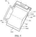
- Embodiment 2 shown in FIG. 5 a drum 200 and a tub 300 of a clothes dryer 100 are inclined upwards.
- a rear wall 320 of the tub 300 is provided with a cooling water supply device 801.
- the cooling water supply device 801 is the same as or similar to the cooling water supply device 8 of Embodiment 1 in structure, and has, for example, a water distributor 830, a water inlet pipe, a second hole 811 arranged on the rear wall 320 of the tub, and the like, and structural features of the water distributor 830 are also the same as that in Embodiment 1.
- An inner surface 3002 of the rear wall 320 of the tub has a hydrophilically treated first region 303 below a water outlet region 8100 of the cooling water supply device 801.
- the first region 303 is inclined upwards to facilitate the downward flowing of water flow along a surface of the region.
- the rest of the inner surface 3000 of the tub 300 is a hydrophobic second region 304.
Landscapes
- Engineering & Computer Science (AREA)
- Textile Engineering (AREA)
- Detail Structures Of Washing Machines And Dryers (AREA)
Abstract
Description
- The present invention belongs to the technical field of home appliances, and relates to a clothes dryer having a condensing device.
- A U.S. invention patent with the publication No. of
US 6,279,357 B1 discloses a washer dryer. The washer dryer has a drum installed in a tub through a spider. A rear wall of the tub has recesses. Water flows to the rear wall of the tub from a water inlet device. In a drying mode, the drum rotates, and moist air leaves the drum and is agitated under the rotation of the drum. The flowing water is in contact with the moist air, so as to improve the condensing effect on the air before the air is heated and returns back to the drum along a circulation path. - Generally, a gap between the tub and the drum is very small. Moreover, a drum wall often has holes for facilitating passage of water or air. In addition, in a drying process, process air in the tub and drum flows quickly under the action of a fan. There is a high possibility that cooling water enters the drum after entering the tub to wet the clothes therein.
- The present invention is directed to an existing clothes dryer.
- The present invention provides a clothes dryer, including a drum for accommodating clothes and a tub surrounding the drum. A drum wall has first holes in dense distribution enabling the drum to be in spatial communication with the tub. A tub wall has a plurality of second holes, and a water outlet region defined by the second holes extends horizontally. A water distributor is provided on the tub wall at an outer side that is away from the drum. The water distributor includes a water inlet and a cover cap covering the second holes. The cover cap has a port hermetically connected with the tub wall. A water storage chamber is formed between the cover cap and the tub wall, where the water storage chamber has a cross-sectional area, which is perpendicular to a water inlet direction, larger than a cross-sectional area of the water inlet.
- The water outlet region may be referred to as a region where the second holes are distributed. When the second holes are arranged orderly in a row, the water outlet region is a continuous surface that takes edges of all the second holes of the row as edges. When the second holes are arranged in multiple rows or arranged irregularly, the water outlet region is a continuous surface enclosed by edges of the second holes at the periphery.
- In comparison with a mode that a water supply pipe directly extends into a narrow space between the tub and the drum, water flows inwards directly from the tub wall, which not only makes installation simpler, but also makes the water flow along an inner surface of the tub wall instead of dropping from the middle of a limited gap, significantly reducing the possibility of water entering the drum. Water flow flowing along the wall surface is not liable to be blown away by airflow to enter the drum.
- A cross-sectional area of the water storage chamber is larger than the cross-sectional area of the water inlet, such that the water flow is buffered in the water storage chamber, and the water can flow out of the second holes relatively uniformly at a relatively smooth flow rate. The uniform and smooth water flow flows along the inner surface of the tub wall, is not prone to entering the drum and also realizes a larger heat exchange area, so that higher heat exchange efficiency is obtained.
- The drum and the tub are substantially cylindrical and are axially horizontal or inclined, and the water distributor may be arranged on a side wall and/or a rear wall of the tub.
- In some embodiments, the drum and the tub are axially horizontal. The water distributor is arranged on the side wall of the tub. The water outlet region is close to or below a horizontal plane where a tub central axis is located. Since the tub wall above the horizontal plane where the tub central axis is located has a downward curved curvature, when the water outlet region is set too high, under the action of gravity, the water flowing out of the water outlet region is prone to dripping onto the drum and enters the drum.
- The water outlet region may be implemented to be connected with a higher upper region of the water storage chamber, such that the water enters the water storage chamber from the water inlet to gather at the bottom of the water storage chamber; then the water level rises; finally the water arrives at the position of the water outlet region to slowly overflow from the second holes. Such a configuration makes the water flow entering the tub be further even and smooth, preventing the water flow from entering the drum and improving the heat exchange efficiency at the same time.
- The improvement of the present invention further includes the inner surface of the tub wall has a hydrophilically treated first region below the water outlet region, and the rest is a hydrophobic second region. The hydrophilically treated inner surface spreads the water flow flowing through to flow through a larger area, so as to increase the heat exchange area, thereby increasing the heat exchange efficiency.
- Hydrophilic treatment may include at least one of electrical spark etching, laser etching, spraying hydrophilic coating, and plasma treatment.
- The water distributor is connected to a water inlet pipe. The water inlet pipe is provided with a water valve controlled by a control device, and the water valve is opened in a process that the control device controls to run a drying process.
- The clothes dryer further includes a fan and a heating device operably communicating with a drying space enclosed by the tub, and the fan and the heating device are started under the control of the control device in a process that the control device runs the drying process. Operably communicating with the drying space enclosed by the tub may be referred to as that any one of the fan and the heating device may be directly located in the drying space enclosed by the tub and may also be located in a space communicating with the drying space.
- A more advantageous improvement further includes that a total cross-sectional area of the second holes is larger than the cross-sectional area of the water inlet on the water distributor. Hence, the water flowing out of the second holes cannot be affected by water pressure of the water inlet, and cannot enter the drum caused by a jet phenomenon.
- Specific embodiments of the present invention will be exemplified below with reference to the accompanying drawings.
-
FIG. 1 is a side view showing main functional components of a clothes dryer according to Embodiment 1; -
FIG. 2 is a partial view of a side wall of a tub; -
FIG. 3 is a schematic cross-sectional view of a partial tub and a cooling water supply device; -
FIG. 4 is a three-dimensional view of a water distributor and a partial inlet pipe; and -
FIG. 5 is a side view showing main functional components of a clothes dryer according to Embodiment 2. - As shown in
FIG. 1 , a clothes dryer 1 according to Embodiment 1 has arotatable drum 2 for accommodating clothes and atub 3 surrounding thedrum 2. Thedrum 2 and thetub 3 are substantially coaxially arranged, and axially substantially horizontal. Adrum wall 21 hasfirst holes 22 in dense distribution enabling the drum to be in spatial communication with thetub 3. A rear end of thetub 3 is connected to aninlet 41 of anair passage 4. Anoutlet 42 of theair passage 4 is connected to asealing ring 5 installed on a front portion of thetub 3, such that theair passage 4 and thetub 3 form a communicating space. Afan 6 and aheating device 7 are arranged in theair passage 4. - A cooling
water supply device 8 is connected with acylindrical side wall 31 of thetub 3. The coolingwater supply device 8 has a group ofsecond holes 81 horizontally arranged on theside wall 31 of the tub. The coolingwater supply device 8 further includes awater inlet pipe 82 and awater distributor 83 connected to thewater inlet pipe 82. Thewater inlet pipe 82 is provided with awater valve 84 controlled by acontrol device 10. Thewater valve 84 is opened in a process that thecontrol device 10 controls to run a drying process. Cooling water enters thewater distributor 83 from thewater inlet pipe 82 to be buffered, and then enters thetub 3 through thesecond holes 81. - As shown in
FIG. 3 and FIG. 4 , thewater distributor 83 is provided on theside wall 31 of thetub 3 at an outer side that is away from thedrum 2. Thewater distributor 83 includes awater inlet 85 and acover cap 86 covering thesecond holes 81. Thecover cap 86 has aport 87 hermetically connected with theside wall 31 of the tub. Awater storage chamber 80 is formed between thecover cap 86 and theside wall 31 of thetub 3, where the water storage chamber has a cross-sectional area, which is perpendicular to a water inlet direction, larger than a cross-sectional area of thewater inlet 85. - The
second holes 81 are connected with a higherupper region 80a of thewater storage chamber 80. - A total cross-sectional area of the
second holes 81 is larger than the cross-sectional area of thewater inlet 85 on thewater distributor 83. - As shown in
FIG. 1 and FIG. 2 , an entireinner surface 30 of thetub 3 is pre-fabricated to be hydrophobic, and then hydrophilic treatment is performed below awater outlet region 810 where thesecond holes 81 are located, such that a hydrophilically treatedfirst region 301 is formed on theinner surface 30 of theside wall 31 of the tub below the water outlet region, and the rest of theinner surface 30 of thetub 3 is a hydrophobicsecond region 302. - The hydrophilic treatment includes at least one of electrical spark etching, laser etching, spraying hydrophilic coating, and plasma treatment.
- The
first region 301 is located at a lower position relative to acentral axis 9 of thetub 3. At this position, the hydrophilicfirst region 301 is curved upwards. The coolingwater supply device 8 is close to a horizontal plane where thecentral axis 9 is located. The cooling water flows out of thesecond holes 81 and then flows to the hydrophilicfirst region 301 under the action of gravity to form a water film. - In the drying process, the
control device 10 starts thefan 6 to circulate process air for drying between theair passage 4 and thetub 3. Thecontrol device 10 also starts theheating device 7 to heat the process air passing through theair passage 4. The high-temperature process air enters thetub 3 and thedrum 2 placed inside thetub 3 to evaporate moisture in the clothes. The coolingwater supply device 8 supplies cooling water to thetub 3. The high-temperature and high-humidity process air exchanges heat with the cooling water film when passing through thefirst region 301. A temperature of the process air drops, such that the carried moisture is condensed into water and separated from the process air. The dry process air enters theair passage 4 to be reheated to enter a next cycle, such that the moisture in the clothes is gradually evaporated. - The cooling
water supply devices 8 may be respectively arranged on both sides of thetub 3. - In
Embodiment 2 shown inFIG. 5 , adrum 200 and atub 300 of aclothes dryer 100 are inclined upwards. Arear wall 320 of thetub 300 is provided with a coolingwater supply device 801. The coolingwater supply device 801 is the same as or similar to the coolingwater supply device 8 of Embodiment 1 in structure, and has, for example, awater distributor 830, a water inlet pipe, asecond hole 811 arranged on therear wall 320 of the tub, and the like, and structural features of thewater distributor 830 are also the same as that in Embodiment 1. - An
inner surface 3002 of therear wall 320 of the tub has a hydrophilically treatedfirst region 303 below awater outlet region 8100 of the coolingwater supply device 801. Thefirst region 303 is inclined upwards to facilitate the downward flowing of water flow along a surface of the region. The rest of theinner surface 3000 of thetub 300 is a hydrophobicsecond region 304. - Specific embodiments described above and illustrated in the accompanying drawings are merely intended to describe the present invention. Any form of variations made by a person of ordinary skill in the art to the present invention within the scope of the basic technical idea of the present invention falls within the protection scope of the present invention.
Claims (9)
- A clothes dryer, comprising a drum (2, 200) for accommodating clothes and a tub (3, 300) surrounding the drum, a drum wall (21) having first holes (22) in dense distribution enabling the drum to be in spatial communication with the tub, wherein a tub wall (31, 320) has a plurality of second holes (81, 811), a water outlet region (810, 8200) defined by the second holes extends horizontally, a water distributor (83, 830) is provided on the tub wall at an outer side that is away from the drum, the water distributor comprises a water inlet (85) and a cover cap (86) covering the second holes, the cover cap has a port (87) hermetically connected with the tub wall, and a water storage chamber (80) is formed between the cover cap and the tub wall, wherein the water storage chamber has a cross-sectional area, which is perpendicular to a water inlet direction, larger than a cross-sectional area of the water inlet.
- The clothes dryer according to claim 1, wherein the drum and the tub are substantially cylindrical, and are axially horizontal or inclined, and the water distributor is arranged on a side wall (31) and/or a rear wall (320) of the tub.
- The clothes dryer according to claim 2, wherein the drum and the tub are axially horizontal, the water distributor (83) is arranged on the side wall (31) of the tub, and the water outlet region (810) is close to or lower than a horizontal plane where a tub central axis (9) is located.
- The clothes dryer according to claim 1, wherein the water outlet region is connected with a higher upper region (80a) of the water storage chamber.
- The clothes dryer according to claim 1, wherein an inner surface (30, 3000) of the tub wall has a hydrophilically treated first region (301, 303) below the water outlet region, and the rest is a hydrophobic second region (302, 304).
- The clothes dryer according to claim 5, wherein the hydrophilic treatment comprises at least one of electrical spark etching, laser etching, spraying hydrophilic coating, and plasma treatment.
- The clothes dryer according to claim 1, wherein the water distributor is connected to a water inlet pipe (82), the water inlet pipe is provided with a water valve (84) controlled by a control device (10), and the water valve is opened in a process that the control device controls to run a drying process.
- The clothes dryer according to claim 7, comprising a fan (6) and a heating device (7) operably communicating with a drying space enclosed by the tub, wherein the fan and the heating device are started under the control of the control device in a process that the control device runs the drying process.
- The clothes dryer according to claim 1, wherein a total cross-sectional area of the second holes (81) is larger than the cross-sectional area of the water inlet (85) on the water distributor.
Priority Applications (1)
| Application Number | Priority Date | Filing Date | Title |
|---|---|---|---|
| PL19212894T PL3666966T3 (en) | 2018-12-13 | 2019-12-02 | Clothes dryer |
Applications Claiming Priority (1)
| Application Number | Priority Date | Filing Date | Title |
|---|---|---|---|
| CN201811522399.4A CN111321567B (en) | 2018-12-13 | 2018-12-13 | Clothes dryer |
Publications (2)
| Publication Number | Publication Date |
|---|---|
| EP3666966A1 true EP3666966A1 (en) | 2020-06-17 |
| EP3666966B1 EP3666966B1 (en) | 2021-10-27 |
Family
ID=68762622
Family Applications (1)
| Application Number | Title | Priority Date | Filing Date |
|---|---|---|---|
| EP19212894.0A Active EP3666966B1 (en) | 2018-12-13 | 2019-12-02 | Clothes dryer |
Country Status (3)
| Country | Link |
|---|---|
| EP (1) | EP3666966B1 (en) |
| CN (1) | CN111321567B (en) |
| PL (1) | PL3666966T3 (en) |
Citations (4)
| Publication number | Priority date | Publication date | Assignee | Title |
|---|---|---|---|---|
| US6279357B1 (en) | 1998-06-18 | 2001-08-28 | General Domestic Appliances Limited | Washer dryer |
| US20030233854A1 (en) * | 2002-06-09 | 2003-12-25 | Matsushita Electric Industrial Co., Ltd. | Drum type washing and drying machine |
| KR101481596B1 (en) * | 2014-03-11 | 2015-01-14 | 엘지전자 주식회사 | Laundry treating machine |
| CN106702669A (en) * | 2015-11-13 | 2017-05-24 | 苏州三星电子有限公司 | Self-cleaning washing machine and spraying method for self-cleaning material |
Family Cites Families (8)
| Publication number | Priority date | Publication date | Assignee | Title |
|---|---|---|---|---|
| JP2004121587A (en) * | 2002-10-03 | 2004-04-22 | Matsushita Electric Ind Co Ltd | Washing and drying machine |
| CN101498089B (en) * | 2008-01-31 | 2010-12-01 | 博西华电器(江苏)有限公司 | Method for treating clothes and electrical equipment used for treating clothes |
| CN102115970B (en) * | 2010-01-05 | 2015-04-08 | 海尔集团公司 | High-pressure spraying device for flushing outer wall of inner barrel of washing machine and method for flushing outer wall of inner barrel |
| CN102134801B (en) * | 2010-01-25 | 2012-10-31 | 朱雨轩 | Self-cleaning device for dirt between barrels of washing machine |
| CN203256486U (en) * | 2013-05-22 | 2013-10-30 | 南京乐金熊猫电器有限公司 | Novel washing machine outer drum with condensation type drying function |
| CN105200747A (en) * | 2014-06-10 | 2015-12-30 | 博西华电器(江苏)有限公司 | Clothes dryer |
| CN106894210B (en) * | 2015-12-17 | 2020-07-10 | 博西华电器(江苏)有限公司 | clothes dryer |
| CN207828635U (en) * | 2017-12-29 | 2018-09-07 | Tcl家用电器(合肥)有限公司 | Washing machine and its condensing unit |
-
2018
- 2018-12-13 CN CN201811522399.4A patent/CN111321567B/en active Active
-
2019
- 2019-12-02 EP EP19212894.0A patent/EP3666966B1/en active Active
- 2019-12-02 PL PL19212894T patent/PL3666966T3/en unknown
Patent Citations (4)
| Publication number | Priority date | Publication date | Assignee | Title |
|---|---|---|---|---|
| US6279357B1 (en) | 1998-06-18 | 2001-08-28 | General Domestic Appliances Limited | Washer dryer |
| US20030233854A1 (en) * | 2002-06-09 | 2003-12-25 | Matsushita Electric Industrial Co., Ltd. | Drum type washing and drying machine |
| KR101481596B1 (en) * | 2014-03-11 | 2015-01-14 | 엘지전자 주식회사 | Laundry treating machine |
| CN106702669A (en) * | 2015-11-13 | 2017-05-24 | 苏州三星电子有限公司 | Self-cleaning washing machine and spraying method for self-cleaning material |
Also Published As
| Publication number | Publication date |
|---|---|
| CN111321567A (en) | 2020-06-23 |
| CN111321567B (en) | 2024-04-12 |
| EP3666966B1 (en) | 2021-10-27 |
| PL3666966T3 (en) | 2021-12-27 |
Similar Documents
| Publication | Publication Date | Title |
|---|---|---|
| US8857071B2 (en) | Clothes treating apparatus having heat exchanger cleaning device | |
| KR101792513B1 (en) | Heating cycle drying module of dishwasher using Fan module and PTC Heater | |
| CN117802749B (en) | Clothes processing device and control method | |
| CN101684610B (en) | Clothes drying device | |
| US10280553B2 (en) | Drain pump and clothes dryer having a drain pump | |
| KR20160006064A (en) | Drain pump assembly and dryer for clothes having the same | |
| CN111850934A (en) | A washing-drying integrated washing machine and its drying method | |
| CN102071563A (en) | Clothes drying device | |
| CN113355840B (en) | Drum washing machine with drying function | |
| EP3666966B1 (en) | Clothes dryer | |
| WO2020032714A1 (en) | Dishwasher | |
| CN111850933A (en) | A washing-drying integrated washing machine and its drying method | |
| CN217078123U (en) | Condenser and clothes treatment equipment | |
| EP3666959A1 (en) | Clothes dryer | |
| US10570557B2 (en) | Tumble dryer and a drying method | |
| CN106894210B (en) | clothes dryer | |
| CN215947644U (en) | Clothes treating device | |
| CN214782758U (en) | Clothes treatment equipment and its condenser | |
| CN221345019U (en) | Dehumidification heating device, circulation stoving structure and drying equipment | |
| CN101684605B (en) | Clothes washer-dryer | |
| KR200182315Y1 (en) | Moisture circulation structure of electric induction heating type rice cooker | |
| CN105484002A (en) | Steam ironing apparatus including an iron comprising a sole with a body provided with a heating element mounted thereon | |
| CN113638178B (en) | Clothes processing device | |
| CN119736781A (en) | Clothes processing device and control method | |
| CN116971154A (en) | Drum mechanism, clothing care equipment and clothing care method |
Legal Events
| Date | Code | Title | Description |
|---|---|---|---|
| PUAI | Public reference made under article 153(3) epc to a published international application that has entered the european phase |
Free format text: ORIGINAL CODE: 0009012 |
|
| STAA | Information on the status of an ep patent application or granted ep patent |
Free format text: STATUS: THE APPLICATION HAS BEEN PUBLISHED |
|
| AK | Designated contracting states |
Kind code of ref document: A1 Designated state(s): AL AT BE BG CH CY CZ DE DK EE ES FI FR GB GR HR HU IE IS IT LI LT LU LV MC MK MT NL NO PL PT RO RS SE SI SK SM TR |
|
| AX | Request for extension of the european patent |
Extension state: BA ME |
|
| STAA | Information on the status of an ep patent application or granted ep patent |
Free format text: STATUS: REQUEST FOR EXAMINATION WAS MADE |
|
| 17P | Request for examination filed |
Effective date: 20201217 |
|
| RBV | Designated contracting states (corrected) |
Designated state(s): AL AT BE BG CH CY CZ DE DK EE ES FI FR GB GR HR HU IE IS IT LI LT LU LV MC MK MT NL NO PL PT RO RS SE SI SK SM TR |
|
| RIC1 | Information provided on ipc code assigned before grant |
Ipc: D06F 25/00 20060101ALN20210412BHEP Ipc: D06F 58/24 20060101AFI20210412BHEP |
|
| RIC1 | Information provided on ipc code assigned before grant |
Ipc: D06F 25/00 20060101ALN20210419BHEP Ipc: D06F 58/24 20060101AFI20210419BHEP |
|
| GRAP | Despatch of communication of intention to grant a patent |
Free format text: ORIGINAL CODE: EPIDOSNIGR1 |
|
| STAA | Information on the status of an ep patent application or granted ep patent |
Free format text: STATUS: GRANT OF PATENT IS INTENDED |
|
| RIC1 | Information provided on ipc code assigned before grant |
Ipc: D06F 25/00 20060101ALN20210525BHEP Ipc: D06F 58/24 20060101AFI20210525BHEP |
|
| INTG | Intention to grant announced |
Effective date: 20210609 |
|
| GRAS | Grant fee paid |
Free format text: ORIGINAL CODE: EPIDOSNIGR3 |
|
| GRAA | (expected) grant |
Free format text: ORIGINAL CODE: 0009210 |
|
| STAA | Information on the status of an ep patent application or granted ep patent |
Free format text: STATUS: THE PATENT HAS BEEN GRANTED |
|
| AK | Designated contracting states |
Kind code of ref document: B1 Designated state(s): AL AT BE BG CH CY CZ DE DK EE ES FI FR GB GR HR HU IE IS IT LI LT LU LV MC MK MT NL NO PL PT RO RS SE SI SK SM TR |
|
| REG | Reference to a national code |
Ref country code: GB Ref legal event code: FG4D |
|
| REG | Reference to a national code |
Ref country code: CH Ref legal event code: EP |
|
| REG | Reference to a national code |
Ref country code: AT Ref legal event code: REF Ref document number: 1441887 Country of ref document: AT Kind code of ref document: T Effective date: 20211115 |
|
| REG | Reference to a national code |
Ref country code: DE Ref legal event code: R096 Ref document number: 602019008709 Country of ref document: DE |
|
| REG | Reference to a national code |
Ref country code: IE Ref legal event code: FG4D |
|
| REG | Reference to a national code |
Ref country code: LT Ref legal event code: MG9D |
|
| REG | Reference to a national code |
Ref country code: NL Ref legal event code: MP Effective date: 20211027 |
|
| REG | Reference to a national code |
Ref country code: AT Ref legal event code: MK05 Ref document number: 1441887 Country of ref document: AT Kind code of ref document: T Effective date: 20211027 |
|
| PG25 | Lapsed in a contracting state [announced via postgrant information from national office to epo] |
Ref country code: RS Free format text: LAPSE BECAUSE OF FAILURE TO SUBMIT A TRANSLATION OF THE DESCRIPTION OR TO PAY THE FEE WITHIN THE PRESCRIBED TIME-LIMIT Effective date: 20211027 Ref country code: LT Free format text: LAPSE BECAUSE OF FAILURE TO SUBMIT A TRANSLATION OF THE DESCRIPTION OR TO PAY THE FEE WITHIN THE PRESCRIBED TIME-LIMIT Effective date: 20211027 Ref country code: FI Free format text: LAPSE BECAUSE OF FAILURE TO SUBMIT A TRANSLATION OF THE DESCRIPTION OR TO PAY THE FEE WITHIN THE PRESCRIBED TIME-LIMIT Effective date: 20211027 Ref country code: BG Free format text: LAPSE BECAUSE OF FAILURE TO SUBMIT A TRANSLATION OF THE DESCRIPTION OR TO PAY THE FEE WITHIN THE PRESCRIBED TIME-LIMIT Effective date: 20220127 Ref country code: AT Free format text: LAPSE BECAUSE OF FAILURE TO SUBMIT A TRANSLATION OF THE DESCRIPTION OR TO PAY THE FEE WITHIN THE PRESCRIBED TIME-LIMIT Effective date: 20211027 |
|
| PG25 | Lapsed in a contracting state [announced via postgrant information from national office to epo] |
Ref country code: IS Free format text: LAPSE BECAUSE OF FAILURE TO SUBMIT A TRANSLATION OF THE DESCRIPTION OR TO PAY THE FEE WITHIN THE PRESCRIBED TIME-LIMIT Effective date: 20220227 Ref country code: SE Free format text: LAPSE BECAUSE OF FAILURE TO SUBMIT A TRANSLATION OF THE DESCRIPTION OR TO PAY THE FEE WITHIN THE PRESCRIBED TIME-LIMIT Effective date: 20211027 Ref country code: PT Free format text: LAPSE BECAUSE OF FAILURE TO SUBMIT A TRANSLATION OF THE DESCRIPTION OR TO PAY THE FEE WITHIN THE PRESCRIBED TIME-LIMIT Effective date: 20220228 Ref country code: NO Free format text: LAPSE BECAUSE OF FAILURE TO SUBMIT A TRANSLATION OF THE DESCRIPTION OR TO PAY THE FEE WITHIN THE PRESCRIBED TIME-LIMIT Effective date: 20220127 Ref country code: NL Free format text: LAPSE BECAUSE OF FAILURE TO SUBMIT A TRANSLATION OF THE DESCRIPTION OR TO PAY THE FEE WITHIN THE PRESCRIBED TIME-LIMIT Effective date: 20211027 Ref country code: LV Free format text: LAPSE BECAUSE OF FAILURE TO SUBMIT A TRANSLATION OF THE DESCRIPTION OR TO PAY THE FEE WITHIN THE PRESCRIBED TIME-LIMIT Effective date: 20211027 Ref country code: HR Free format text: LAPSE BECAUSE OF FAILURE TO SUBMIT A TRANSLATION OF THE DESCRIPTION OR TO PAY THE FEE WITHIN THE PRESCRIBED TIME-LIMIT Effective date: 20211027 Ref country code: GR Free format text: LAPSE BECAUSE OF FAILURE TO SUBMIT A TRANSLATION OF THE DESCRIPTION OR TO PAY THE FEE WITHIN THE PRESCRIBED TIME-LIMIT Effective date: 20220128 Ref country code: ES Free format text: LAPSE BECAUSE OF FAILURE TO SUBMIT A TRANSLATION OF THE DESCRIPTION OR TO PAY THE FEE WITHIN THE PRESCRIBED TIME-LIMIT Effective date: 20211027 |
|
| REG | Reference to a national code |
Ref country code: DE Ref legal event code: R097 Ref document number: 602019008709 Country of ref document: DE |
|
| PG25 | Lapsed in a contracting state [announced via postgrant information from national office to epo] |
Ref country code: SM Free format text: LAPSE BECAUSE OF FAILURE TO SUBMIT A TRANSLATION OF THE DESCRIPTION OR TO PAY THE FEE WITHIN THE PRESCRIBED TIME-LIMIT Effective date: 20211027 Ref country code: SK Free format text: LAPSE BECAUSE OF FAILURE TO SUBMIT A TRANSLATION OF THE DESCRIPTION OR TO PAY THE FEE WITHIN THE PRESCRIBED TIME-LIMIT Effective date: 20211027 Ref country code: RO Free format text: LAPSE BECAUSE OF FAILURE TO SUBMIT A TRANSLATION OF THE DESCRIPTION OR TO PAY THE FEE WITHIN THE PRESCRIBED TIME-LIMIT Effective date: 20211027 Ref country code: MC Free format text: LAPSE BECAUSE OF FAILURE TO SUBMIT A TRANSLATION OF THE DESCRIPTION OR TO PAY THE FEE WITHIN THE PRESCRIBED TIME-LIMIT Effective date: 20211027 Ref country code: EE Free format text: LAPSE BECAUSE OF FAILURE TO SUBMIT A TRANSLATION OF THE DESCRIPTION OR TO PAY THE FEE WITHIN THE PRESCRIBED TIME-LIMIT Effective date: 20211027 Ref country code: DK Free format text: LAPSE BECAUSE OF FAILURE TO SUBMIT A TRANSLATION OF THE DESCRIPTION OR TO PAY THE FEE WITHIN THE PRESCRIBED TIME-LIMIT Effective date: 20211027 Ref country code: CZ Free format text: LAPSE BECAUSE OF FAILURE TO SUBMIT A TRANSLATION OF THE DESCRIPTION OR TO PAY THE FEE WITHIN THE PRESCRIBED TIME-LIMIT Effective date: 20211027 |
|
| PLBE | No opposition filed within time limit |
Free format text: ORIGINAL CODE: 0009261 |
|
| STAA | Information on the status of an ep patent application or granted ep patent |
Free format text: STATUS: NO OPPOSITION FILED WITHIN TIME LIMIT |
|
| REG | Reference to a national code |
Ref country code: BE Ref legal event code: MM Effective date: 20211231 |
|
| 26N | No opposition filed |
Effective date: 20220728 |
|
| PG25 | Lapsed in a contracting state [announced via postgrant information from national office to epo] |
Ref country code: LU Free format text: LAPSE BECAUSE OF NON-PAYMENT OF DUE FEES Effective date: 20211202 Ref country code: IE Free format text: LAPSE BECAUSE OF NON-PAYMENT OF DUE FEES Effective date: 20211202 Ref country code: AL Free format text: LAPSE BECAUSE OF FAILURE TO SUBMIT A TRANSLATION OF THE DESCRIPTION OR TO PAY THE FEE WITHIN THE PRESCRIBED TIME-LIMIT Effective date: 20211027 |
|
| PG25 | Lapsed in a contracting state [announced via postgrant information from national office to epo] |
Ref country code: SI Free format text: LAPSE BECAUSE OF FAILURE TO SUBMIT A TRANSLATION OF THE DESCRIPTION OR TO PAY THE FEE WITHIN THE PRESCRIBED TIME-LIMIT Effective date: 20211027 Ref country code: FR Free format text: LAPSE BECAUSE OF NON-PAYMENT OF DUE FEES Effective date: 20211227 Ref country code: BE Free format text: LAPSE BECAUSE OF NON-PAYMENT OF DUE FEES Effective date: 20211231 |
|
| REG | Reference to a national code |
Ref country code: DE Ref legal event code: R084 Ref document number: 602019008709 Country of ref document: DE |
|
| PG25 | Lapsed in a contracting state [announced via postgrant information from national office to epo] |
Ref country code: IT Free format text: LAPSE BECAUSE OF FAILURE TO SUBMIT A TRANSLATION OF THE DESCRIPTION OR TO PAY THE FEE WITHIN THE PRESCRIBED TIME-LIMIT Effective date: 20211027 |
|
| REG | Reference to a national code |
Ref country code: DE Ref legal event code: R085 Ref document number: 602019008709 Country of ref document: DE |
|
| PG25 | Lapsed in a contracting state [announced via postgrant information from national office to epo] |
Ref country code: CY Free format text: LAPSE BECAUSE OF FAILURE TO SUBMIT A TRANSLATION OF THE DESCRIPTION OR TO PAY THE FEE WITHIN THE PRESCRIBED TIME-LIMIT Effective date: 20211027 |
|
| PG25 | Lapsed in a contracting state [announced via postgrant information from national office to epo] |
Ref country code: HU Free format text: LAPSE BECAUSE OF FAILURE TO SUBMIT A TRANSLATION OF THE DESCRIPTION OR TO PAY THE FEE WITHIN THE PRESCRIBED TIME-LIMIT; INVALID AB INITIO Effective date: 20191202 |
|
| REG | Reference to a national code |
Ref country code: CH Ref legal event code: PL |
|
| PG25 | Lapsed in a contracting state [announced via postgrant information from national office to epo] |
Ref country code: LI Free format text: LAPSE BECAUSE OF NON-PAYMENT OF DUE FEES Effective date: 20221231 Ref country code: CH Free format text: LAPSE BECAUSE OF NON-PAYMENT OF DUE FEES Effective date: 20221231 |
|
| PG25 | Lapsed in a contracting state [announced via postgrant information from national office to epo] |
Ref country code: MK Free format text: LAPSE BECAUSE OF FAILURE TO SUBMIT A TRANSLATION OF THE DESCRIPTION OR TO PAY THE FEE WITHIN THE PRESCRIBED TIME-LIMIT Effective date: 20211027 |
|
| GBPC | Gb: european patent ceased through non-payment of renewal fee |
Effective date: 20231202 |
|
| PG25 | Lapsed in a contracting state [announced via postgrant information from national office to epo] |
Ref country code: MT Free format text: LAPSE BECAUSE OF FAILURE TO SUBMIT A TRANSLATION OF THE DESCRIPTION OR TO PAY THE FEE WITHIN THE PRESCRIBED TIME-LIMIT Effective date: 20211027 |
|
| PG25 | Lapsed in a contracting state [announced via postgrant information from national office to epo] |
Ref country code: GB Free format text: LAPSE BECAUSE OF NON-PAYMENT OF DUE FEES Effective date: 20231202 |
|
| PG25 | Lapsed in a contracting state [announced via postgrant information from national office to epo] |
Ref country code: GB Free format text: LAPSE BECAUSE OF NON-PAYMENT OF DUE FEES Effective date: 20231202 |
|
| PGFP | Annual fee paid to national office [announced via postgrant information from national office to epo] |
Ref country code: TR Payment date: 20251127 Year of fee payment: 7 |
|
| PGFP | Annual fee paid to national office [announced via postgrant information from national office to epo] |
Ref country code: PL Payment date: 20251124 Year of fee payment: 7 |
|
| PGFP | Annual fee paid to national office [announced via postgrant information from national office to epo] |
Ref country code: DE Payment date: 20251231 Year of fee payment: 7 |