EP3666651A1 - Composite potable water tank and method of forming - Google Patents
Composite potable water tank and method of forming Download PDFInfo
- Publication number
- EP3666651A1 EP3666651A1 EP19215118.1A EP19215118A EP3666651A1 EP 3666651 A1 EP3666651 A1 EP 3666651A1 EP 19215118 A EP19215118 A EP 19215118A EP 3666651 A1 EP3666651 A1 EP 3666651A1
- Authority
- EP
- European Patent Office
- Prior art keywords
- water tank
- panel
- side panel
- tank
- interior
- Prior art date
- Legal status (The legal status is an assumption and is not a legal conclusion. Google has not performed a legal analysis and makes no representation as to the accuracy of the status listed.)
- Granted
Links
Images


Classifications
-
- B—PERFORMING OPERATIONS; TRANSPORTING
- B64—AIRCRAFT; AVIATION; COSMONAUTICS
- B64D—EQUIPMENT FOR FITTING IN OR TO AIRCRAFT; FLIGHT SUITS; PARACHUTES; ARRANGEMENT OR MOUNTING OF POWER PLANTS OR PROPULSION TRANSMISSIONS IN AIRCRAFT
- B64D11/00—Passenger or crew accommodation; Flight-deck installations not otherwise provided for
- B64D11/02—Toilet fittings
-
- B—PERFORMING OPERATIONS; TRANSPORTING
- B65—CONVEYING; PACKING; STORING; HANDLING THIN OR FILAMENTARY MATERIAL
- B65D—CONTAINERS FOR STORAGE OR TRANSPORT OF ARTICLES OR MATERIALS, e.g. BAGS, BARRELS, BOTTLES, BOXES, CANS, CARTONS, CRATES, DRUMS, JARS, TANKS, HOPPERS, FORWARDING CONTAINERS; ACCESSORIES, CLOSURES, OR FITTINGS THEREFOR; PACKAGING ELEMENTS; PACKAGES
- B65D1/00—Rigid or semi-rigid containers having bodies formed in one piece, e.g. by casting metallic material, by moulding plastics, by blowing vitreous material, by throwing ceramic material, by moulding pulped fibrous material or by deep-drawing operations performed on sheet material
- B65D1/22—Boxes or like containers with side walls of substantial depth for enclosing contents
- B65D1/24—Boxes or like containers with side walls of substantial depth for enclosing contents with moulded compartments or partitions
-
- B—PERFORMING OPERATIONS; TRANSPORTING
- B65—CONVEYING; PACKING; STORING; HANDLING THIN OR FILAMENTARY MATERIAL
- B65D—CONTAINERS FOR STORAGE OR TRANSPORT OF ARTICLES OR MATERIALS, e.g. BAGS, BARRELS, BOTTLES, BOXES, CANS, CARTONS, CRATES, DRUMS, JARS, TANKS, HOPPERS, FORWARDING CONTAINERS; ACCESSORIES, CLOSURES, OR FITTINGS THEREFOR; PACKAGING ELEMENTS; PACKAGES
- B65D25/00—Details of other kinds or types of rigid or semi-rigid containers
- B65D25/02—Internal fittings
-
- B—PERFORMING OPERATIONS; TRANSPORTING
- B29—WORKING OF PLASTICS; WORKING OF SUBSTANCES IN A PLASTIC STATE IN GENERAL
- B29C—SHAPING OR JOINING OF PLASTICS; SHAPING OF MATERIAL IN A PLASTIC STATE, NOT OTHERWISE PROVIDED FOR; AFTER-TREATMENT OF THE SHAPED PRODUCTS, e.g. REPAIRING
- B29C43/00—Compression moulding, i.e. applying external pressure to flow the moulding material; Apparatus therefor
- B29C43/02—Compression moulding, i.e. applying external pressure to flow the moulding material; Apparatus therefor of articles of definite length, i.e. discrete articles
-
- B—PERFORMING OPERATIONS; TRANSPORTING
- B64—AIRCRAFT; AVIATION; COSMONAUTICS
- B64D—EQUIPMENT FOR FITTING IN OR TO AIRCRAFT; FLIGHT SUITS; PARACHUTES; ARRANGEMENT OR MOUNTING OF POWER PLANTS OR PROPULSION TRANSMISSIONS IN AIRCRAFT
- B64D11/00—Passenger or crew accommodation; Flight-deck installations not otherwise provided for
-
- B—PERFORMING OPERATIONS; TRANSPORTING
- B29—WORKING OF PLASTICS; WORKING OF SUBSTANCES IN A PLASTIC STATE IN GENERAL
- B29L—INDEXING SCHEME ASSOCIATED WITH SUBCLASS B29C, RELATING TO PARTICULAR ARTICLES
- B29L2031/00—Other particular articles
- B29L2031/712—Containers; Packaging elements or accessories, Packages
- B29L2031/7162—Boxes, cartons, cases
Definitions
- Exemplary embodiments pertain to the art of water systems. More specifically, the present disclosure relates to potable water systems utilizing conformal-shaped water storage tanks.
- potable water systems to provide water for use by passengers during operation.
- some potable water systems include a large water storage tank which is pressurized with air. The air typically is bleed air from an auxiliary power unit or is provided by a standalone air compressor for the potable water system.
- Aircraft operators typically desire the tank to maximize water volume storage capability, while also minimizing interior aircraft space utilized by the water storage tank. For this reason, the water storage tank is often made to an irregular or conformal shape, meant to fit in an irregular-shaped space allotted for the water storage tank at the interior of the aircraft.
- a water tank in one embodiment, includes a compression molded tank shell.
- the tank shell includes a back panel and a side panel extending from the back panel.
- the side panel defines an outer perimeter of the water tank.
- a compression molded front panel is secured to the side panel to enclose an interior of the water tank.
- one or more baffles are positioned in the interior of the water tank.
- the one or more baffles are secured to one of the side panel or the back panel by welding.
- the front panel is secured to the side panel via welding.
- the liner is a high density polyethylene (HDPE), polyetheretherketone (PEEK) or polypropylene (PP) in the form of a powder coating, film or sheet.
- HDPE high density polyethylene
- PEEK polyetheretherketone
- PP polypropylene
- one or more baffle sheets are formed and the one or more baffle sheets are installed in the interior prior to securing the front panel to the side panel.
- the front panel is secured to the side panel via welding.
- one or more accessory components or fittings are secured to one or more of the side panel, the front panel or the back panel.
- a liner is installed in the interior of the water tank prior to securing the front panel to the side panel.
- the tank shell is formed of a plurality of fibers suspended in a thermoplastic resin.
- the liner is a high density polyethylene (HDPE), polyetheretherketone (PEEK) or polypropylene (PP) in the form of a powder coating, film or sheet.
- HDPE high density polyethylene
- PEEK polyetheretherketone
- PP polypropylene
- the front wall 12 and the back wall 14 are flat and planar, while the side wall 16 has a curvilinear profile around the perimeter of the water tank 10.
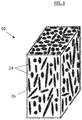
- the water tank 10 is formed from a composite or molded construction of a plurality of fibers 24 suspended in a thermoplastic resin 26 formed via, for example, a compression molding process.
- the plurality of fibers 24 are oriented randomly, which enables mechanical properties of the composite part in all directions, or isotropically, similar to metal materials.
- the plurality of fibers 24 are short or chopped carbon fiber or glass fiber.
- the thermoplastic resin 26 is a thermoplastic material such as polyetheretherketone (PEEK), polyaryletherketone (PAEK), or polyphenylene sulfide (PPS), for example, while other thermoplastic resin materials may be used in other embodiments.
- PEEK polyetheretherketone
- PAEK polyaryletherketone
- PPS polyphenylene sulfide
- the compression molded composite structure of the water tank 10 withstands the selected hydrostatic pressure of the interior of the water tank 10, and additionally provides insulation due to the thermoplastic resin, which has low thermal conductivity.
- the baffles 28 are formed from extruded sheets of thermoplastic material or thermoplastic material reinforced with short or chopped carbon fibers or glass fibers. Once the plurality of baffles 28 are installed, the front wall 12 is installed to enclose the water tank 10.
- the tank inlet 18, the tank outlet 20 and the one or more fittings 22 may be formed using thermoplastic based composite material and may be, for example, cocured with or welded to the water tank 10.
- the configurations of water tank 10 disclosed herein results in a lightweight water tank 10, compared to prior art metal water tanks, due at least in part to the density of the composite material being 1/3 that of a typical metal material.
- the compression molded water tank 10 has improved toughness, and meets flame, smoke and toxicity requirements.
- the material is weldable and the process time needed to construct the water tank 10 is relatively short, in some cases compression molding process takes between 10 and 30 minutes. Due to the insulative properties of the compression molded material, the tank capacity is increased or alternatively occupies a smaller space because of the reduced insulation thickness needed.
Landscapes
- Engineering & Computer Science (AREA)
- Mechanical Engineering (AREA)
- Aviation & Aerospace Engineering (AREA)
- Ceramic Engineering (AREA)
- Moulding By Coating Moulds (AREA)
- Filling Or Discharging Of Gas Storage Vessels (AREA)
- Casting Or Compression Moulding Of Plastics Or The Like (AREA)
- Pressure Vessels And Lids Thereof (AREA)
- Lining Or Joining Of Plastics Or The Like (AREA)
Abstract
Description
- This application claims the benefit of Indian Application No.
201811047034 filed December 12, 2018 - Exemplary embodiments pertain to the art of water systems. More specifically, the present disclosure relates to potable water systems utilizing conformal-shaped water storage tanks.
- Many applications, such as passenger aircraft, passenger trains, or the like often include potable water systems to provide water for use by passengers during operation. In an aircraft, for example, some potable water systems include a large water storage tank which is pressurized with air. The air typically is bleed air from an auxiliary power unit or is provided by a standalone air compressor for the potable water system. Aircraft operators typically desire the tank to maximize water volume storage capability, while also minimizing interior aircraft space utilized by the water storage tank. For this reason, the water storage tank is often made to an irregular or conformal shape, meant to fit in an irregular-shaped space allotted for the water storage tank at the interior of the aircraft.
- In one embodiment, a water tank includes a compression molded tank shell. The tank shell includes a back panel and a side panel extending from the back panel. The side panel defines an outer perimeter of the water tank. A compression molded front panel is secured to the side panel to enclose an interior of the water tank.
- Additionally or alternatively, in this or other embodiments one or more baffles are positioned in the interior of the water tank.
- Additionally or alternatively, in this or other embodiments the one or more baffles are secured to one of the side panel or the back panel by welding.
- Additionally or alternatively, in this or other embodiments the one or more baffles are positioned in one or more slots formed in the side panel.
- Additionally or alternatively, in this or other embodiments the front panel is secured to the side panel via welding.
- Additionally or alternatively, in this or other embodiments one or more accessory components or fittings are secured to one or more of the side panel, the front panel or the back panel.
- Additionally or alternatively, in this or other embodiments the tank shell is formed of a plurality of fibers suspended in a thermoplastic resin.
- Additionally or alternatively, in this or other embodiments the plurality of fibers are carbon fibers or glass fibers.
- Additionally or alternatively, in this or other embodiments the thermoplastic resin is one of polyetheretherketone (PEEK), polyaryletherketone (PAEK), or polyphenylene sulfide (PPS).
- Additionally or alternatively, in this or other embodiments a liner is located in the interior of the water tank.
- Additionally or alternatively, in this or other embodiments the liner is a high density polyethylene (HDPE), polyetheretherketone (PEEK) or polypropylene (PP) in the form of a powder coating, film or sheet.
- In another embodiment, a method of forming a potable water tank includes forming a tank shell via a compression molding process, the tank shell including a back panel and a side panel extending from the back panel, the side panel defining an outer perimeter of the water tank. A front panel is separately formed by compression molding, and the front panel is secured to the side panel thereby enclosing an interior of the water tank.
- Additionally or alternatively, in this or other embodiments one or more baffle sheets are formed and the one or more baffle sheets are installed in the interior prior to securing the front panel to the side panel.
- Additionally or alternatively, in this or other embodiments the one or more baffle sheets are secured to one of the side panel or the back panel via welding.
- Additionally or alternatively, in this or other embodiments the one or more baffle sheets are installed into one or more slots formed in one of the side panel or the back panel.
- Additionally or alternatively, in this or other embodiments the front panel is secured to the side panel via welding.
- Additionally or alternatively, in this or other embodiments one or more accessory components or fittings are secured to one or more of the side panel, the front panel or the back panel.
- Additionally or alternatively, in this or other embodiments a liner is installed in the interior of the water tank prior to securing the front panel to the side panel.
- Additionally or alternatively, in this or other embodiments the tank shell is formed of a plurality of fibers suspended in a thermoplastic resin.
- Additionally or alternatively, in this or other embodiments the liner is a high density polyethylene (HDPE), polyetheretherketone (PEEK) or polypropylene (PP) in the form of a powder coating, film or sheet.
- The following descriptions should not be considered limiting in any way. With reference to the accompanying drawings, like elements are numbered alike:
-
FIG. 1 is a perspective view of an embodiment of a water tank; -
FIG. 2 is a side view of an embodiment of a water tank; -
FIG. 3 is a schematic illustration of a material utilized in formation of a water tank; -
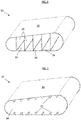
FIG. 4 is schematic illustration of a baffle arrangement in a water tank; -
FIG. 5 is a schematic illustration of another baffle arrangement in a water tank; and -
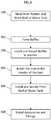
FIG. 6 is a schematic illustration of a method of making a water tank. - A detailed description of one or more embodiments of the disclosed apparatus and method are presented herein by way of exemplification and not limitation with reference to the Figures.
- Referring to
FIG. 1 , shown is a schematic view of apotable water tank 10 for use in, for example, an aircraft or the like. In some embodiments, thewater tank 10 is sized, for example, to hold 20 gallons of water and additional free air space. Thewater tank 10 includes afront wall 12, a back wall 14 (shown inFIG. 2 ), and aside wall 16 extending between thefront wall 12 and theback wall 14. Theside wall 16 defines an outer perimeter of thewater tank 10. Thewater tank 10 has atank inlet 18 and atank outlet 20, which in some embodiments are accessory components attached to, for example, theside wall 16. Thetank inlet 18 and thetank outlet 20 are configured to admit water to thewater tank 10 and egress water from thewater tank 10, respectively. Further, thewater tank 10 may include one ormore fittings 22 bonded or otherwise attached to thewater tank 10, for example at theside wall 16. - As shown in
FIGs. 1 and2 , in some embodiments thefront wall 12 and theback wall 14 are flat and planar, while theside wall 16 has a curvilinear profile around the perimeter of thewater tank 10. - Referring now to
FIG. 3 , thewater tank 10 is formed from a composite or molded construction of a plurality offibers 24 suspended in athermoplastic resin 26 formed via, for example, a compression molding process. In some embodiments, as shown inFIG. 3 , the plurality offibers 24 are oriented randomly, which enables mechanical properties of the composite part in all directions, or isotropically, similar to metal materials. In some embodiments, the plurality offibers 24 are short or chopped carbon fiber or glass fiber. Thethermoplastic resin 26 is a thermoplastic material such as polyetheretherketone (PEEK), polyaryletherketone (PAEK), or polyphenylene sulfide (PPS), for example, while other thermoplastic resin materials may be used in other embodiments. The compression molded composite structure of thewater tank 10 withstands the selected hydrostatic pressure of the interior of thewater tank 10, and additionally provides insulation due to the thermoplastic resin, which has low thermal conductivity. - Referring now to
FIG. 4 , theinterior 30 of thewater tank 10 has one ormore baffles 28 located therein. Thebaffles 28 extend between, for example, thefront wall 12 and theback wall 14, and/or between portions of theside wall 16. In some embodiments, such as illustrated inFIG. 4 , thebaffles 28 are secured in theinterior 30 by welding thebaffles 28 to theback wall 14 and/or theside wall 16. In other embodiments, referring now toFIG. 5 , mountingfeatures 32 such as slots or brackets are formed in theside wall 16 and/or theback wall 14. Thebaffles 28 are installed by inserting thebaffles 28 into the mounting features 32 to position and retain thebaffles 28 in place in theinterior 30 of thewater tank 10. In some embodiments, thebaffles 28 are formed from extruded sheets of thermoplastic material or thermoplastic material reinforced with short or chopped carbon fibers or glass fibers. Once the plurality ofbaffles 28 are installed, thefront wall 12 is installed to enclose thewater tank 10. Thetank inlet 18, thetank outlet 20 and the one ormore fittings 22 may be formed using thermoplastic based composite material and may be, for example, cocured with or welded to thewater tank 10. - Referring again to
FIG. 4 , in some embodiments the interior 30 of thewater tank 10 includes aliner 34 to prevent water leakage and compressed air leakage through thewater tank 10. In some embodiments, the liner is a high density polyethylene (HDPE), polyetheretherketone (PEEK) or polypropylene (PP) in the form of a powder coating, film or sheet which may be sprayed or bonded to theinterior wall 36 including thefront wall 12 of thewater tank 10. Theliner 34 may be cured either by a localized flame spray operation or by placement into an oven at appropriate temperature. Alternatively, the film orsheet liner material 34 may be applied by a thermoforming bladder process. - Referring now to
FIG. 6 , illustrated is a schematic of a method of making afuel tank 10. Referring to block 100, a main portion of thewater tank 10, including theback wall 14 and theside wall 16 is compression molded. Thefront wall 12 is also separately compression molded atblock 100. Thebaffles 28 are formed atblock 102, and installed into and secured in theinterior 30 of thewater tank 10 by welding or joining. Atblock 104, theliner 34 material is applied and secured to the interior 30 of thewater tank 10. Also, atblock 105,liner 34 material is applied on the inside of thefront wall 12. Atblock 106, thefront wall 12 is secured to thewater tank 10 by, for example, welding, thus enclosing thewater tank 10, and atblock 108 accessories orfittings 22 are installed by, for example, co-curing or welding. - The configurations of
water tank 10 disclosed herein results in alightweight water tank 10, compared to prior art metal water tanks, due at least in part to the density of the composite material being 1/3 that of a typical metal material. The compression moldedwater tank 10 has improved toughness, and meets flame, smoke and toxicity requirements. The material is weldable and the process time needed to construct thewater tank 10 is relatively short, in some cases compression molding process takes between 10 and 30 minutes. Due to the insulative properties of the compression molded material, the tank capacity is increased or alternatively occupies a smaller space because of the reduced insulation thickness needed. - The term "about" is intended to include the degree of error associated with measurement of the particular quantity based upon the equipment available at the time of filing the application.
- The terminology used herein is for the purpose of describing particular embodiments only and is not intended to be limiting of the present disclosure. As used herein, the singular forms "a", "an" and "the" are intended to include the plural forms as well, unless the context clearly indicates otherwise. It will be further understood that the terms "comprises" and/or "comprising," when used in this specification, specify the presence of stated features, integers, steps, operations, elements, and/or components, but do not preclude the presence or addition of one or more other features, integers, steps, operations, element components, and/or groups thereof.
- While the present disclosure has been described with reference to an exemplary embodiment or embodiments, it will be understood by those skilled in the art that various changes may be made and equivalents may be substituted for elements thereof without departing from the scope of the invention as defined by the claims. In addition, many modifications may be made to adapt a particular situation or material to the teachings of the present disclosure without departing from the scope of the invention. Therefore, it is intended that the present disclosure not be limited to the particular embodiment disclosed as the best mode contemplated for carrying out this present disclosure, but that the present disclosure will include all embodiments falling within the scope of the claims.
Claims (15)
- A water tank comprising:a compression molded tank shell, the tank shell including:a back panel (14); anda side panel (16) extending from the back panel, the side panel defining an outer perimeter of the water tank; anda compression molded front panel (12) secured to the side panel to enclose an interior of the water tank.
- The water tank of claim 1, further comprising one or more baffles (28) disposed in the interior of the water tank.
- The water tank of claim 2, wherein the one or more baffles are secured to one of the side panel or the back panel by welding and/or wherein the one or more baffles are disposed in one or more slots (32) formed in the side panel.
- The water tank of any preceding claim, wherein the front panel is secured to the side panel via welding.
- The water tank of any preceding claim, further comprising one or more accessory components or fittings secured to one or more of the side panel, the front panel or the back panel.
- The water tank of any preceding claim, wherein the tank shell is formed of a plurality of fibers suspended in a thermoplastic resin, and optionally wherein the plurality of fibers are carbon fibers or glass fibers and optionally wherein the thermoplastic resin is one of polyetheretherketone (PEEK), polyaryletherketone (PAEK), or polyphenylene sulfide (PPS).
- The water tank of any preceding claim, further comprising a liner (34) disposed in the interior of the water tank, and optionally wherein the liner is a high density polyethylene (HDPE), polyetheretherketone (PEEK) or polypropylene (PP) in the form of a powder coating, film or sheet.
- A method of forming a potable water tank, comprising:forming a tank shell via a compression molding process, the tank shell including:a back panel; anda side panel extending from the back panel, the side panel defining an outer perimeter of the water tank;separately forming a front panel by compression molding; andsecuring the front panel to the side panel thereby enclosing an interior of the water tank.
- The method of claim 8, further comprising:forming one or more baffle sheets; andinstalling the one or more baffle sheets in the interior prior to securing the front panel to the side panel.
- The method of claim 9, wherein the one or more baffle sheets are secured to one of the side panel or the back panel via welding and/or wherein the one or more baffle sheets are installed into one or more slots formed in one of the side panel or the back panel.
- The method of claim 8, 9 or 10, further comprising securing the front panel is to the side panel via welding.
- The method of any of claims 8 to 11, further comprising securing one or more accessory components or fittings to one or more of the side panel, the front panel or the back panel.
- The method of any of claims 8 to 12, further comprising installing a liner in the interior of the water tank prior to securing the front panel to the side panel.
- The method of any of claims 8 to 13, wherein the tank shell is formed of a plurality of fibers suspended in a thermoplastic resin.
- The method of claim 13, wherein the liner is a high density polyethylene (HDPE), polyetheretherketone (PEEK) or polypropylene (PP) in the form of a powder coating, film or sheet.
Applications Claiming Priority (1)
| Application Number | Priority Date | Filing Date | Title |
|---|---|---|---|
| IN201811047034 | 2018-12-12 |
Publications (2)
| Publication Number | Publication Date |
|---|---|
| EP3666651A1 true EP3666651A1 (en) | 2020-06-17 |
| EP3666651B1 EP3666651B1 (en) | 2023-08-16 |
Family
ID=68886745
Family Applications (1)
| Application Number | Title | Priority Date | Filing Date |
|---|---|---|---|
| EP19215118.1A Active EP3666651B1 (en) | 2018-12-12 | 2019-12-11 | Composite potable water tank and method of forming |
Country Status (6)
| Country | Link |
|---|---|
| US (1) | US20200189786A1 (en) |
| EP (1) | EP3666651B1 (en) |
| JP (1) | JP2020094482A (en) |
| CN (1) | CN111301825A (en) |
| BR (1) | BR102019026113A2 (en) |
| CA (1) | CA3064396A1 (en) |
Citations (7)
| Publication number | Priority date | Publication date | Assignee | Title |
|---|---|---|---|---|
| US4982856A (en) * | 1989-06-23 | 1991-01-08 | General Electric Company | High temperature, high pressure continuous random glass fiber reinforced thermoplastic fluid vessel and method of making |
| US20060060289A1 (en) * | 2001-10-12 | 2006-03-23 | Polymer & Steel Technologies Holding Company, L.L.C. | Composite pressure vessel assembly and method |
| CA2778930A1 (en) * | 2009-11-06 | 2011-05-12 | The Boeing Company | Compression molding method and reinforced thermoplastic parts molded thereby |
| EP3061709A1 (en) * | 2013-10-25 | 2016-08-31 | The Yokohama Rubber Co., Ltd. | Aircraft water tank |
| US20160257403A1 (en) * | 2013-10-30 | 2016-09-08 | The Yokohama Rubber Co., Ltd. | Aircraft Water Tank |
| EP3219613A1 (en) * | 2016-03-16 | 2017-09-20 | Goodrich Corporation | Pressurized potable water system with conformal shape water storage tank |
| EP3450314A1 (en) * | 2017-08-29 | 2019-03-06 | Goodrich Corporation | Conformable tank with sandwich structure walls |
Family Cites Families (7)
| Publication number | Priority date | Publication date | Assignee | Title |
|---|---|---|---|---|
| CA1152462A (en) * | 1980-07-30 | 1983-08-23 | White (George) & Sons Inc. | Tank-baffle system |
| DE3912270A1 (en) * | 1988-04-30 | 1990-10-18 | Holger Knappe | PLASTIC CONTAINER FOR LIQUIDS OR GASES |
| US5651474A (en) * | 1994-12-22 | 1997-07-29 | The United States Of America As Represented By The Secretary Of The Air Force | Cryogenic structures |
| SE514401C2 (en) * | 1999-06-29 | 2001-02-19 | Teknikkusten Ab | Device for fuel tank for heavy vehicles and process for making the tank |
| US7238409B1 (en) * | 2002-05-23 | 2007-07-03 | Rohr, Inc. | Structural element with rib-receiving member |
| WO2007035592A2 (en) * | 2005-09-19 | 2007-03-29 | Advanced Technology Materials, Inc. | Drain connector for substance processing receptacle |
| US20160130078A1 (en) * | 2014-11-06 | 2016-05-12 | i3 Capital Partners, LLC | Bladder Systems for Dual Use of Truck Tanks |
-
2019
- 2019-07-12 US US16/509,912 patent/US20200189786A1/en not_active Abandoned
- 2019-12-09 CA CA3064396A patent/CA3064396A1/en active Pending
- 2019-12-10 BR BR102019026113-7A patent/BR102019026113A2/en not_active IP Right Cessation
- 2019-12-10 JP JP2019222606A patent/JP2020094482A/en active Pending
- 2019-12-11 EP EP19215118.1A patent/EP3666651B1/en active Active
- 2019-12-11 CN CN201911271957.9A patent/CN111301825A/en active Pending
Patent Citations (7)
| Publication number | Priority date | Publication date | Assignee | Title |
|---|---|---|---|---|
| US4982856A (en) * | 1989-06-23 | 1991-01-08 | General Electric Company | High temperature, high pressure continuous random glass fiber reinforced thermoplastic fluid vessel and method of making |
| US20060060289A1 (en) * | 2001-10-12 | 2006-03-23 | Polymer & Steel Technologies Holding Company, L.L.C. | Composite pressure vessel assembly and method |
| CA2778930A1 (en) * | 2009-11-06 | 2011-05-12 | The Boeing Company | Compression molding method and reinforced thermoplastic parts molded thereby |
| EP3061709A1 (en) * | 2013-10-25 | 2016-08-31 | The Yokohama Rubber Co., Ltd. | Aircraft water tank |
| US20160257403A1 (en) * | 2013-10-30 | 2016-09-08 | The Yokohama Rubber Co., Ltd. | Aircraft Water Tank |
| EP3219613A1 (en) * | 2016-03-16 | 2017-09-20 | Goodrich Corporation | Pressurized potable water system with conformal shape water storage tank |
| EP3450314A1 (en) * | 2017-08-29 | 2019-03-06 | Goodrich Corporation | Conformable tank with sandwich structure walls |
Also Published As
| Publication number | Publication date |
|---|---|
| US20200189786A1 (en) | 2020-06-18 |
| CN111301825A (en) | 2020-06-19 |
| EP3666651B1 (en) | 2023-08-16 |
| BR102019026113A2 (en) | 2020-07-14 |
| CA3064396A1 (en) | 2020-06-12 |
| JP2020094482A (en) | 2020-06-18 |
Similar Documents
| Publication | Publication Date | Title |
|---|---|---|
| US11310872B2 (en) | Metal and composite leading edge assemblies | |
| US8096441B2 (en) | Sealing structure for high-pressure container | |
| US20180283610A1 (en) | Tank enclosure and tank mount system and method | |
| CN105050845B (en) | Method for manufacturing fuel tank and fuel tank | |
| CA2873587C (en) | Hybrid component and production method | |
| JP5541095B2 (en) | tank | |
| GB2203713A (en) | Removable or hinged component for covering openings in the fuselage of an aircraft | |
| WO2008156505A1 (en) | Light weight thermoplastic flex foam and hybrid duct system | |
| RU2413119C2 (en) | Method to manufacture pipeline | |
| US20150217624A1 (en) | Cross-car structural support with integrated hvac floor duct | |
| US9545770B2 (en) | Dis-bond membrane for a lined pressure vessel | |
| US20160264242A1 (en) | Aircraft galley monument structure | |
| CN103079863B (en) | Fuel tanks made of thermoplastic material | |
| EP3666651B1 (en) | Composite potable water tank and method of forming | |
| EP0454978A1 (en) | Plastic fuel tank and method for molding the same | |
| US8393436B2 (en) | Flexible muffler for use in aircraft environmental control systems and method of manufacture | |
| EP3182028B1 (en) | Air supply duct with honeycomb acoustic liner | |
| JP5748909B2 (en) | Manufacturing method for vehicle air conditioner cover | |
| US20060199491A1 (en) | Beam for reinforcing a vehicle cockpit organized to receive a module for the selective distribution of air from a heating, ventilation and/or air conditioning system | |
| US20190376629A1 (en) | Fluid circulation pipe for motor vehicle, method for manufacturing same and use thereof as motor vehicle engine coolant hose | |
| CN116890985A (en) | Aircraft sandwich panel, related propulsion unit and aircraft, and manufacturing method | |
| US12049070B2 (en) | Laminated structure | |
| US20130026201A1 (en) | Container for a supply unit, oxygen supply device and passenger supply unit and system of an arrangement of a number of containers | |
| EP2550995B1 (en) | Container for a supply unit, oxygen supply device and passenger supply unit and system of an arrangement of a number of containers | |
| US20160213962A1 (en) | Systems for shield and flange support |
Legal Events
| Date | Code | Title | Description |
|---|---|---|---|
| PUAI | Public reference made under article 153(3) epc to a published international application that has entered the european phase |
Free format text: ORIGINAL CODE: 0009012 |
|
| STAA | Information on the status of an ep patent application or granted ep patent |
Free format text: STATUS: THE APPLICATION HAS BEEN PUBLISHED |
|
| AK | Designated contracting states |
Kind code of ref document: A1 Designated state(s): AL AT BE BG CH CY CZ DE DK EE ES FI FR GB GR HR HU IE IS IT LI LT LU LV MC MK MT NL NO PL PT RO RS SE SI SK SM TR |
|
| AX | Request for extension of the european patent |
Extension state: BA ME |
|
| STAA | Information on the status of an ep patent application or granted ep patent |
Free format text: STATUS: REQUEST FOR EXAMINATION WAS MADE |
|
| 17P | Request for examination filed |
Effective date: 20201217 |
|
| RBV | Designated contracting states (corrected) |
Designated state(s): AL AT BE BG CH CY CZ DE DK EE ES FI FR GB GR HR HU IE IS IT LI LT LU LV MC MK MT NL NO PL PT RO RS SE SI SK SM TR |
|
| STAA | Information on the status of an ep patent application or granted ep patent |
Free format text: STATUS: EXAMINATION IS IN PROGRESS |
|
| 17Q | First examination report despatched |
Effective date: 20211013 |
|
| GRAP | Despatch of communication of intention to grant a patent |
Free format text: ORIGINAL CODE: EPIDOSNIGR1 |
|
| STAA | Information on the status of an ep patent application or granted ep patent |
Free format text: STATUS: GRANT OF PATENT IS INTENDED |
|
| INTG | Intention to grant announced |
Effective date: 20230314 |
|
| GRAS | Grant fee paid |
Free format text: ORIGINAL CODE: EPIDOSNIGR3 |
|
| GRAA | (expected) grant |
Free format text: ORIGINAL CODE: 0009210 |
|
| STAA | Information on the status of an ep patent application or granted ep patent |
Free format text: STATUS: THE PATENT HAS BEEN GRANTED |
|
| AK | Designated contracting states |
Kind code of ref document: B1 Designated state(s): AL AT BE BG CH CY CZ DE DK EE ES FI FR GB GR HR HU IE IS IT LI LT LU LV MC MK MT NL NO PL PT RO RS SE SI SK SM TR |
|
| REG | Reference to a national code |
Ref country code: CH Ref legal event code: EP |
|
| REG | Reference to a national code |
Ref country code: DE Ref legal event code: R096 Ref document number: 602019035025 Country of ref document: DE |
|
| REG | Reference to a national code |
Ref country code: IE Ref legal event code: FG4D |
|
| P01 | Opt-out of the competence of the unified patent court (upc) registered |
Effective date: 20230922 |
|
| REG | Reference to a national code |
Ref country code: LT Ref legal event code: MG9D |
|
| REG | Reference to a national code |
Ref country code: NL Ref legal event code: MP Effective date: 20230816 |
|
| REG | Reference to a national code |
Ref country code: AT Ref legal event code: MK05 Ref document number: 1599831 Country of ref document: AT Kind code of ref document: T Effective date: 20230816 |
|
| PG25 | Lapsed in a contracting state [announced via postgrant information from national office to epo] |
Ref country code: GR Free format text: LAPSE BECAUSE OF FAILURE TO SUBMIT A TRANSLATION OF THE DESCRIPTION OR TO PAY THE FEE WITHIN THE PRESCRIBED TIME-LIMIT Effective date: 20231117 |
|
| PG25 | Lapsed in a contracting state [announced via postgrant information from national office to epo] |
Ref country code: IS Free format text: LAPSE BECAUSE OF FAILURE TO SUBMIT A TRANSLATION OF THE DESCRIPTION OR TO PAY THE FEE WITHIN THE PRESCRIBED TIME-LIMIT Effective date: 20231216 |
|
| PG25 | Lapsed in a contracting state [announced via postgrant information from national office to epo] |
Ref country code: SE Free format text: LAPSE BECAUSE OF FAILURE TO SUBMIT A TRANSLATION OF THE DESCRIPTION OR TO PAY THE FEE WITHIN THE PRESCRIBED TIME-LIMIT Effective date: 20230816 Ref country code: RS Free format text: LAPSE BECAUSE OF FAILURE TO SUBMIT A TRANSLATION OF THE DESCRIPTION OR TO PAY THE FEE WITHIN THE PRESCRIBED TIME-LIMIT Effective date: 20230816 Ref country code: PT Free format text: LAPSE BECAUSE OF FAILURE TO SUBMIT A TRANSLATION OF THE DESCRIPTION OR TO PAY THE FEE WITHIN THE PRESCRIBED TIME-LIMIT Effective date: 20231218 Ref country code: NO Free format text: LAPSE BECAUSE OF FAILURE TO SUBMIT A TRANSLATION OF THE DESCRIPTION OR TO PAY THE FEE WITHIN THE PRESCRIBED TIME-LIMIT Effective date: 20231116 Ref country code: NL Free format text: LAPSE BECAUSE OF FAILURE TO SUBMIT A TRANSLATION OF THE DESCRIPTION OR TO PAY THE FEE WITHIN THE PRESCRIBED TIME-LIMIT Effective date: 20230816 Ref country code: LV Free format text: LAPSE BECAUSE OF FAILURE TO SUBMIT A TRANSLATION OF THE DESCRIPTION OR TO PAY THE FEE WITHIN THE PRESCRIBED TIME-LIMIT Effective date: 20230816 Ref country code: LT Free format text: LAPSE BECAUSE OF FAILURE TO SUBMIT A TRANSLATION OF THE DESCRIPTION OR TO PAY THE FEE WITHIN THE PRESCRIBED TIME-LIMIT Effective date: 20230816 Ref country code: IS Free format text: LAPSE BECAUSE OF FAILURE TO SUBMIT A TRANSLATION OF THE DESCRIPTION OR TO PAY THE FEE WITHIN THE PRESCRIBED TIME-LIMIT Effective date: 20231216 Ref country code: HR Free format text: LAPSE BECAUSE OF FAILURE TO SUBMIT A TRANSLATION OF THE DESCRIPTION OR TO PAY THE FEE WITHIN THE PRESCRIBED TIME-LIMIT Effective date: 20230816 Ref country code: GR Free format text: LAPSE BECAUSE OF FAILURE TO SUBMIT A TRANSLATION OF THE DESCRIPTION OR TO PAY THE FEE WITHIN THE PRESCRIBED TIME-LIMIT Effective date: 20231117 Ref country code: FI Free format text: LAPSE BECAUSE OF FAILURE TO SUBMIT A TRANSLATION OF THE DESCRIPTION OR TO PAY THE FEE WITHIN THE PRESCRIBED TIME-LIMIT Effective date: 20230816 Ref country code: AT Free format text: LAPSE BECAUSE OF FAILURE TO SUBMIT A TRANSLATION OF THE DESCRIPTION OR TO PAY THE FEE WITHIN THE PRESCRIBED TIME-LIMIT Effective date: 20230816 |
|
| PG25 | Lapsed in a contracting state [announced via postgrant information from national office to epo] |
Ref country code: PL Free format text: LAPSE BECAUSE OF FAILURE TO SUBMIT A TRANSLATION OF THE DESCRIPTION OR TO PAY THE FEE WITHIN THE PRESCRIBED TIME-LIMIT Effective date: 20230816 |
|
| PG25 | Lapsed in a contracting state [announced via postgrant information from national office to epo] |
Ref country code: ES Free format text: LAPSE BECAUSE OF FAILURE TO SUBMIT A TRANSLATION OF THE DESCRIPTION OR TO PAY THE FEE WITHIN THE PRESCRIBED TIME-LIMIT Effective date: 20230816 |
|
| PG25 | Lapsed in a contracting state [announced via postgrant information from national office to epo] |
Ref country code: SM Free format text: LAPSE BECAUSE OF FAILURE TO SUBMIT A TRANSLATION OF THE DESCRIPTION OR TO PAY THE FEE WITHIN THE PRESCRIBED TIME-LIMIT Effective date: 20230816 Ref country code: RO Free format text: LAPSE BECAUSE OF FAILURE TO SUBMIT A TRANSLATION OF THE DESCRIPTION OR TO PAY THE FEE WITHIN THE PRESCRIBED TIME-LIMIT Effective date: 20230816 Ref country code: ES Free format text: LAPSE BECAUSE OF FAILURE TO SUBMIT A TRANSLATION OF THE DESCRIPTION OR TO PAY THE FEE WITHIN THE PRESCRIBED TIME-LIMIT Effective date: 20230816 Ref country code: EE Free format text: LAPSE BECAUSE OF FAILURE TO SUBMIT A TRANSLATION OF THE DESCRIPTION OR TO PAY THE FEE WITHIN THE PRESCRIBED TIME-LIMIT Effective date: 20230816 Ref country code: DK Free format text: LAPSE BECAUSE OF FAILURE TO SUBMIT A TRANSLATION OF THE DESCRIPTION OR TO PAY THE FEE WITHIN THE PRESCRIBED TIME-LIMIT Effective date: 20230816 Ref country code: CZ Free format text: LAPSE BECAUSE OF FAILURE TO SUBMIT A TRANSLATION OF THE DESCRIPTION OR TO PAY THE FEE WITHIN THE PRESCRIBED TIME-LIMIT Effective date: 20230816 Ref country code: SK Free format text: LAPSE BECAUSE OF FAILURE TO SUBMIT A TRANSLATION OF THE DESCRIPTION OR TO PAY THE FEE WITHIN THE PRESCRIBED TIME-LIMIT Effective date: 20230816 |
|
| REG | Reference to a national code |
Ref country code: DE Ref legal event code: R097 Ref document number: 602019035025 Country of ref document: DE |
|
| PLBE | No opposition filed within time limit |
Free format text: ORIGINAL CODE: 0009261 |
|
| STAA | Information on the status of an ep patent application or granted ep patent |
Free format text: STATUS: NO OPPOSITION FILED WITHIN TIME LIMIT |
|
| 26N | No opposition filed |
Effective date: 20240517 |
|
| PG25 | Lapsed in a contracting state [announced via postgrant information from national office to epo] |
Ref country code: IT Free format text: LAPSE BECAUSE OF FAILURE TO SUBMIT A TRANSLATION OF THE DESCRIPTION OR TO PAY THE FEE WITHIN THE PRESCRIBED TIME-LIMIT Effective date: 20230816 Ref country code: SI Free format text: LAPSE BECAUSE OF FAILURE TO SUBMIT A TRANSLATION OF THE DESCRIPTION OR TO PAY THE FEE WITHIN THE PRESCRIBED TIME-LIMIT Effective date: 20230816 |
|
| REG | Reference to a national code |
Ref country code: CH Ref legal event code: PL |
|
| PG25 | Lapsed in a contracting state [announced via postgrant information from national office to epo] |
Ref country code: LU Free format text: LAPSE BECAUSE OF NON-PAYMENT OF DUE FEES Effective date: 20231211 |
|
| PG25 | Lapsed in a contracting state [announced via postgrant information from national office to epo] |
Ref country code: MC Free format text: LAPSE BECAUSE OF FAILURE TO SUBMIT A TRANSLATION OF THE DESCRIPTION OR TO PAY THE FEE WITHIN THE PRESCRIBED TIME-LIMIT Effective date: 20230816 |
|
| REG | Reference to a national code |
Ref country code: BE Ref legal event code: MM Effective date: 20231231 |
|
| PG25 | Lapsed in a contracting state [announced via postgrant information from national office to epo] |
Ref country code: MC Free format text: LAPSE BECAUSE OF FAILURE TO SUBMIT A TRANSLATION OF THE DESCRIPTION OR TO PAY THE FEE WITHIN THE PRESCRIBED TIME-LIMIT Effective date: 20230816 Ref country code: LU Free format text: LAPSE BECAUSE OF NON-PAYMENT OF DUE FEES Effective date: 20231211 |
|
| REG | Reference to a national code |
Ref country code: IE Ref legal event code: MM4A |
|
| PG25 | Lapsed in a contracting state [announced via postgrant information from national office to epo] |
Ref country code: IE Free format text: LAPSE BECAUSE OF NON-PAYMENT OF DUE FEES Effective date: 20231211 |
|
| PG25 | Lapsed in a contracting state [announced via postgrant information from national office to epo] |
Ref country code: BE Free format text: LAPSE BECAUSE OF NON-PAYMENT OF DUE FEES Effective date: 20231231 |
|
| PG25 | Lapsed in a contracting state [announced via postgrant information from national office to epo] |
Ref country code: CH Free format text: LAPSE BECAUSE OF NON-PAYMENT OF DUE FEES Effective date: 20231231 |
|
| PG25 | Lapsed in a contracting state [announced via postgrant information from national office to epo] |
Ref country code: IE Free format text: LAPSE BECAUSE OF NON-PAYMENT OF DUE FEES Effective date: 20231211 Ref country code: CH Free format text: LAPSE BECAUSE OF NON-PAYMENT OF DUE FEES Effective date: 20231231 Ref country code: BE Free format text: LAPSE BECAUSE OF NON-PAYMENT OF DUE FEES Effective date: 20231231 |
|
| PG25 | Lapsed in a contracting state [announced via postgrant information from national office to epo] |
Ref country code: BG Free format text: LAPSE BECAUSE OF FAILURE TO SUBMIT A TRANSLATION OF THE DESCRIPTION OR TO PAY THE FEE WITHIN THE PRESCRIBED TIME-LIMIT Effective date: 20230816 |
|
| PG25 | Lapsed in a contracting state [announced via postgrant information from national office to epo] |
Ref country code: BG Free format text: LAPSE BECAUSE OF FAILURE TO SUBMIT A TRANSLATION OF THE DESCRIPTION OR TO PAY THE FEE WITHIN THE PRESCRIBED TIME-LIMIT Effective date: 20230816 |
|
| PG25 | Lapsed in a contracting state [announced via postgrant information from national office to epo] |
Ref country code: CY Free format text: LAPSE BECAUSE OF FAILURE TO SUBMIT A TRANSLATION OF THE DESCRIPTION OR TO PAY THE FEE WITHIN THE PRESCRIBED TIME-LIMIT; INVALID AB INITIO Effective date: 20191211 |
|
| PG25 | Lapsed in a contracting state [announced via postgrant information from national office to epo] |
Ref country code: HU Free format text: LAPSE BECAUSE OF FAILURE TO SUBMIT A TRANSLATION OF THE DESCRIPTION OR TO PAY THE FEE WITHIN THE PRESCRIBED TIME-LIMIT; INVALID AB INITIO Effective date: 20191211 |
|
| PG25 | Lapsed in a contracting state [announced via postgrant information from national office to epo] |
Ref country code: TR Free format text: LAPSE BECAUSE OF FAILURE TO SUBMIT A TRANSLATION OF THE DESCRIPTION OR TO PAY THE FEE WITHIN THE PRESCRIBED TIME-LIMIT Effective date: 20230816 |
|
| PGFP | Annual fee paid to national office [announced via postgrant information from national office to epo] |
Ref country code: DE Payment date: 20251126 Year of fee payment: 7 |
|
| PGFP | Annual fee paid to national office [announced via postgrant information from national office to epo] |
Ref country code: GB Payment date: 20251120 Year of fee payment: 7 |
|
| PGFP | Annual fee paid to national office [announced via postgrant information from national office to epo] |
Ref country code: FR Payment date: 20251119 Year of fee payment: 7 |