EP3666644A1 - System to promote accelerated boundary layer ingestion - Google Patents
System to promote accelerated boundary layer ingestion Download PDFInfo
- Publication number
- EP3666644A1 EP3666644A1 EP19216036.4A EP19216036A EP3666644A1 EP 3666644 A1 EP3666644 A1 EP 3666644A1 EP 19216036 A EP19216036 A EP 19216036A EP 3666644 A1 EP3666644 A1 EP 3666644A1
- Authority
- EP
- European Patent Office
- Prior art keywords
- fuselage
- nozzle element
- boundary layer
- airflows
- inlet
- Prior art date
- Legal status (The legal status is an assumption and is not a legal conclusion. Google has not performed a legal analysis and makes no representation as to the accuracy of the status listed.)
- Granted
Links
Images

Classifications
-
- B—PERFORMING OPERATIONS; TRANSPORTING
- B64—AIRCRAFT; AVIATION; COSMONAUTICS
- B64C—AEROPLANES; HELICOPTERS
- B64C1/00—Fuselages; Constructional features common to fuselages, wings, stabilising surfaces or the like
- B64C1/16—Fuselages; Constructional features common to fuselages, wings, stabilising surfaces or the like specially adapted for mounting power plant
-
- B—PERFORMING OPERATIONS; TRANSPORTING
- B64—AIRCRAFT; AVIATION; COSMONAUTICS
- B64C—AEROPLANES; HELICOPTERS
- B64C21/00—Influencing air flow over aircraft surfaces by affecting boundary layer flow
- B64C21/01—Boundary layer ingestion [BLI] propulsion
-
- B—PERFORMING OPERATIONS; TRANSPORTING
- B64—AIRCRAFT; AVIATION; COSMONAUTICS
- B64C—AEROPLANES; HELICOPTERS
- B64C21/00—Influencing air flow over aircraft surfaces by affecting boundary layer flow
- B64C21/02—Influencing air flow over aircraft surfaces by affecting boundary layer flow by use of slot, ducts, porous areas or the like
- B64C21/08—Influencing air flow over aircraft surfaces by affecting boundary layer flow by use of slot, ducts, porous areas or the like adjustable
-
- B—PERFORMING OPERATIONS; TRANSPORTING
- B64—AIRCRAFT; AVIATION; COSMONAUTICS
- B64D—EQUIPMENT FOR FITTING IN OR TO AIRCRAFT; FLIGHT SUITS; PARACHUTES; ARRANGEMENT OR MOUNTING OF POWER PLANTS OR PROPULSION TRANSMISSIONS IN AIRCRAFT
- B64D27/00—Arrangement or mounting of power plants in aircraft; Aircraft characterised by the type or position of power plants
- B64D27/02—Aircraft characterised by the type or position of power plants
- B64D27/10—Aircraft characterised by the type or position of power plants of gas-turbine type
- B64D27/14—Aircraft characterised by the type or position of power plants of gas-turbine type within, or attached to, fuselages
-
- B—PERFORMING OPERATIONS; TRANSPORTING
- B64—AIRCRAFT; AVIATION; COSMONAUTICS
- B64D—EQUIPMENT FOR FITTING IN OR TO AIRCRAFT; FLIGHT SUITS; PARACHUTES; ARRANGEMENT OR MOUNTING OF POWER PLANTS OR PROPULSION TRANSMISSIONS IN AIRCRAFT
- B64D27/00—Arrangement or mounting of power plants in aircraft; Aircraft characterised by the type or position of power plants
- B64D27/02—Aircraft characterised by the type or position of power plants
- B64D27/16—Aircraft characterised by the type or position of power plants of jet type
- B64D27/20—Aircraft characterised by the type or position of power plants of jet type within, or attached to, fuselages
-
- B—PERFORMING OPERATIONS; TRANSPORTING
- B64—AIRCRAFT; AVIATION; COSMONAUTICS
- B64D—EQUIPMENT FOR FITTING IN OR TO AIRCRAFT; FLIGHT SUITS; PARACHUTES; ARRANGEMENT OR MOUNTING OF POWER PLANTS OR PROPULSION TRANSMISSIONS IN AIRCRAFT
- B64D33/00—Arrangement in aircraft of power plant parts or auxiliaries not otherwise provided for
- B64D33/02—Arrangement in aircraft of power plant parts or auxiliaries not otherwise provided for of combustion air intakes
-
- B—PERFORMING OPERATIONS; TRANSPORTING
- B64—AIRCRAFT; AVIATION; COSMONAUTICS
- B64C—AEROPLANES; HELICOPTERS
- B64C2230/00—Boundary layer controls
- B64C2230/06—Boundary layer controls by explicitly adjusting fluid flow, e.g. by using valves, variable aperture or slot areas, variable pump action or variable fluid pressure
-
- B—PERFORMING OPERATIONS; TRANSPORTING
- B64—AIRCRAFT; AVIATION; COSMONAUTICS
- B64C—AEROPLANES; HELICOPTERS
- B64C2230/00—Boundary layer controls
- B64C2230/20—Boundary layer controls by passively inducing fluid flow, e.g. by means of a pressure difference between both ends of a slot or duct
-
- B—PERFORMING OPERATIONS; TRANSPORTING
- B64—AIRCRAFT; AVIATION; COSMONAUTICS
- B64D—EQUIPMENT FOR FITTING IN OR TO AIRCRAFT; FLIGHT SUITS; PARACHUTES; ARRANGEMENT OR MOUNTING OF POWER PLANTS OR PROPULSION TRANSMISSIONS IN AIRCRAFT
- B64D33/00—Arrangement in aircraft of power plant parts or auxiliaries not otherwise provided for
- B64D33/02—Arrangement in aircraft of power plant parts or auxiliaries not otherwise provided for of combustion air intakes
- B64D2033/0226—Arrangement in aircraft of power plant parts or auxiliaries not otherwise provided for of combustion air intakes comprising boundary layer control means
-
- Y—GENERAL TAGGING OF NEW TECHNOLOGICAL DEVELOPMENTS; GENERAL TAGGING OF CROSS-SECTIONAL TECHNOLOGIES SPANNING OVER SEVERAL SECTIONS OF THE IPC; TECHNICAL SUBJECTS COVERED BY FORMER USPC CROSS-REFERENCE ART COLLECTIONS [XRACs] AND DIGESTS
- Y02—TECHNOLOGIES OR APPLICATIONS FOR MITIGATION OR ADAPTATION AGAINST CLIMATE CHANGE
- Y02T—CLIMATE CHANGE MITIGATION TECHNOLOGIES RELATED TO TRANSPORTATION
- Y02T50/00—Aeronautics or air transport
- Y02T50/10—Drag reduction
Definitions
- Exemplary embodiments of the present disclosure relate generally to aircraft and, in one embodiment, to a system to promote accelerated boundary layer ingestion on an aircraft.
- Certain aircraft are configured with a fuselage having a nose cone in front and a tail section opposite the nose cone, aerodynamic wings extending outwardly from opposite sides of the fuselage and a tail or rudder assembly at the tail section.
- the tail or rudder assembly can include a rear pylon and one or more aerodynamic tail wings extending outwardly from the fuselage and the pylon.
- the aerodynamic wings, the pylon and the aerodynamic tail wings can include controllable surfaces that allow for controlled flight operations.
- Propulsive force for the aircraft can be provided by engine nacelles.
- the engine nacelles can be supported below the aerodynamic wings in some cases or on either side of the fuselage at the tail section in other cases.
- the engines ingest air flowing as a boundary layer along the fuselage via the respective fan sections of the engines. While such boundary layer ingestion can provide propulsive efficiency benefits, these benefits are often reduced in practice by adverse effects of inlet distortions on fan efficiencies.
- an aircraft includes fuselage having a nose, a main section aft of the nose and a tail aft of the main section, an engine nacelle partially embedded in the tail and including a boundary layer ingestion (BLI) propulsor with an inlet directly adjacent to the fuselage and a nozzle element disposed upstream from the inlet and configured to accelerate boundary flows flowing toward the interior side of the engine nacelle.
- BLI boundary layer ingestion
- the propulsor may include a fan in the inlet.
- the nozzle element may have a step-wise curvature and an annular curvature about a longitudinal axis of the fuselage.
- the nozzle element may include a forward end, an aft end and an intermediate section interposed between the forward and aft ends and may include an inward curvature connected with the forward end and an outward curvature connected with the aft end.
- the forward end may be separate from the fuselage by a first average distance
- the aft end may be separate from the fuselage by a second average distance and the first average distance may exceed the second average distance.
- a vane may extend outwardly from the fuselage to support the nozzle element.
- the nozzle element may be selectively deployable.
- the nozzle element may be stowable within a nozzle element chamber of the fuselage.
- a controller may be configured to deploy the nozzle element in accordance with current aircraft conditions.
- Also disclosed herein is a system to promote boundary layer ingestion for an aircraft comprising a fuselage; a boundary layer ingestion (BLI) propulsor inlet; and a nozzle element disposed upstream from the BLI propulsor inlet and configured to accelerate boundary flows flowing toward an interior side of the BLI propulsor inlet.
- BLI boundary layer ingestion
- a system to promote boundary layer ingestion includes a boundary layer ingestion (BLI) propulsor inlet, fuselage along which airflows flow as boundary layer airflows toward the BLI propulsor inlet, the fuselage being configured to distort a profile of the boundary layer airflows and a nozzle element disposed upstream from the BLI propulsor inlet and downstream from a distortion of the boundary layer airflows by the fuselage and configured to homogenize the profile of the boundary layer airflows.
- BLI boundary layer ingestion
- the BLI propulsor inlet may include a fan.
- the nozzle element may have a step-wise curvature and an annular curvature about a longitudinal axis of the fuselage.
- the nozzle element may include a forward end, an aft end and an intermediate section interposed between the forward and aft ends and may include an inward curvature connected with the forward end and an outward curvature connected with the aft end.
- the forward end may be separate from the fuselage by a first average distance
- the aft end may be separate from the fuselage by a second average distance and the first average distance may exceed the second average distance.
- a vane may extend outwardly from the fuselage to support the nozzle element.
- the nozzle element may be selectively deployable.
- the nozzle element may be stowable within a nozzle element chamber of the curved section.
- a controller may be configured to deploy the nozzle element in accordance with current aircraft conditions.
- a system to promote boundary layer ingestion includes a boundary layer ingestion (BLI) propulsor inlet including interior and exterior sides, fuselage along which airflows flow as boundary layer airflows toward the interior and exterior sides of the BLI propulsor inlet, the fuselage being configured to distort a profile of the boundary layer airflows and a nozzle element disposed upstream from the BLI propulsor inlet and downstream from a distortion of the boundary layer airflows by the fuselage.
- BLI boundary layer ingestion
- the nozzle element is configured to homogenize the profile of the boundary layer airflows by accelerating the airflows flowing as boundary layer airflows toward the interior side of the BLI propulsor inlet and decelerating the airflows flowing as boundary layer airflows toward the exterior side of the BLI propulsor inlet.
- the nozzle element may have a step-wise curvature and an annular curvature about a longitudinal axis of the fuselage.
- an aircraft comprising the system of the second or third aspect, the aircraft providing the fuselage along which the airflows flow as the boundary layer airflows.
- the fuselage may have a nose, a main section aft of the nose and a tail aft of the main section.
- An engine nacelle may be partially embedded in the tail and including the boundary layer ingestion (BLI) propulsor with the inlet directly adjacent to the fuselage and the nozzle element disposed upstream from the inlet.
- BLI boundary layer ingestion
- a ram nozzle is placed in front of an inlet of a fan of an aircraft engine.
- the ram nozzle accelerates boundary layer airflows near a fuselage wall and slows other airflows that are more distant from the fuselage wall.
- the ram nozzle thus effectively provides for a more uniform inflow velocity of the airflows flowing into the inlet of the fan.
- an aircraft 101 includes fuselage 110.
- the fuselage 110 has a nose section 111, a main section 112 that is located aft of the nose section 111 and a tail section 113 that is located aft of the main section 112.
- the aircraft 101 also includes aerodynamic wings 114 extending outwardly from opposite sides of the fuselage 110 at the main section 112 and a tail assembly 120 located at the tail section 113.
- the tail assembly 120 has a pylon 121 that extends vertically upwardly from the fuselage 110 and aerodynamic tail wings 122 extending outwardly from opposite sides of the pylon 121.
- the aircraft 101 can further include controllable surfaces on the aerodynamic wings 114, the pylon 121 and the aerodynamic tail wings 122 that can be pivoted in order to facilitate the execution of controlled flight operations.
- each engine nacelle 130 includes a boundary layer ingestion (BLI) propulsor 131 with a BLI propulsor inlet 132 and a fan 133 disposed within the BLI propulsor inlet 132.
- BLI boundary layer ingestion
- the BLI propulsor inlet 132 has an interior side 1321 and an exterior side 1322 and is disposed such that the interior side 1321 is directly adjacent to the fuselage 110 at the tail section 113.
- airflows flowing around the aircraft 101 flow along the fuselage 110 during ground-based and flight operations such that the airflows flow past the nose section 111, then past the main section 112 and then past a forward portion 1131 of the tail section 113 before they enter the BLI propulsor inlet 132 as boundary layer airflows.
- the fuselage 110 at the main section 112 at least partially obscures the span of the fan 133 at the interior side 1321 of the propulsor inlet 132 to the airflows flowing around the aircraft 101 (see FIG. 2 ).
- a curvature 1132 (see FIG. 4 ) of the forward portion 1131 of the tail section 113 curves inwardly toward the interior side 1321 of the propulsor inlet 132 to clear the fuselage 110 from the span of the fan 133 at the interior side 1321 of the BLI propulsor inlet 132.
- viscous scrubbing of the airflows along the fuselage 110 and, to a lesser extent, the curvature 1132 of the forward portion 1131 of the tail section 113 lead to boundary layer airflows closest to the fuselage 110 having reduced velocities as compared to the boundary layer airflows more distant from the fuselage 110 (in some or all cases, the viscous scrubbing has a substantially greater effect of the boundary layer airflows than the curvature 1132). These factors lead to a distortion of a profile of the boundary layer airflows. As a result, the BLI propulsor inlet 132 can receive non-uniform airflows and potential benefits of boundary layer airflow ingestion are reduced due to non-optimized angles of attack for the fan 133 and correspondingly decreased efficiencies.
- the aircraft 101 further includes a nozzle element 140.
- the nozzle element 140 is disposed at the forward portion 1131 of the tail section 113 upstream from the BLI propulsor inlet 132 and downstream from the location(s) of the fuselage 110 where the distortion of the boundary layer profile occurs.
- the nozzle element 140 is configured to homogenize the profile of the boundary layer airflows by accelerating those boundary layer airflows that flow toward the interior side 1321 of the BLI propulsor inlet 132 and, in some cases, to decelerate those boundary layer airflows that flow toward the exterior side 1322 of the BLI propulsor inlet 132.
- the BLI propulsor inlet 132 thus receives more uniform airflows and potential benefits of boundary layer airflow ingestion are restored, maintained or increased due to more optimized angles of attack for the fan 133 and correspondingly increased efficiencies.
- the nozzle element 140 has a step-wise curvature 141 (see FIG. 3 ) toward the forward portion 1131 of the tail section 113 and has an annular curvature 142 (see FIG. 2 ) about a longitudinal axis A (see FIG. 1 ) of the fuselage 110.
- the nozzle element 140 includes a forward end 143, an aft end 144 and an intermediate section 145 that is interposed between the forward end 143 and the aft end 144.
- the intermediate section 145 includes an inward curvature 1451, which is connected with the forward end 143, and an outward curvature 1452, which is connected with the aft end 144, to define the step-wise curvature 141.
- the nozzle element 140 extends axially along the fuselage 110 at the tail section 113 and has an axial curvature that generally mimics the tapering the fuselage 110 at the tail section 113. Nevertheless, the forward end 143 is separate from the forward portion 1131 of the tail section 113 by a first average distance D1, the aft end 144 is separate from the forward portion 1131 of the tail section 113 by a second average distance D2 and the first average distance D1 exceeds the second average distance D2.
- one or more vanes 150 extend outwardly from the fuselage 110 at the tail section 113 to support the nozzle element 140.
- the nozzle element 140 can be deployed permanently or semi-permanently as shown in FIG. 2 or can be selectively deployable as shown in FIG. 5 .
- the nozzle element 140 can be stowed within a nozzle element chamber 501 of the fuselage 110 at the tail section 113 and deployed in accordance with current aircraft or ground-based or flight operation conditions (i.e., when a BLI propulsor efficiency boost is desired from improved boundary layer airflow ingestion by the BLI propulsor inlet 132 resulting from the deployment of the nozzle element 140).
- Selective deployment of the nozzle element 140 can be executed by a controller 160 that is coupled to servo elements 161.
- the servo elements 161 are configured to position the one or more vanes 150 such that the nozzle element 140 is stowed or deployed.
- the controller 160 is configured to control the stowage and deployment of the nozzle element 140 in accordance with current aircraft or current ground-based or flight operation conditions.
- Benefits of the features described herein are the provision of a ram nozzle that can simultaneously accelerate certain boundary layer airflows and decelerate the bulk of the fan inlet airflows to thereby provide for more uniform boundary layer ingestion at the BLI propulsor inlet, to allow a more optimized angle of attack and to provide for higher overall fan efficiency while retaining all of the propulsive efficiency benefits of boundary layer ingestion. These benefits will outweigh pressure losses due to the additional geometry of the ram nozzle.
Landscapes
- Engineering & Computer Science (AREA)
- Aviation & Aerospace Engineering (AREA)
- Chemical & Material Sciences (AREA)
- Combustion & Propulsion (AREA)
- Mechanical Engineering (AREA)
- Traffic Control Systems (AREA)
Abstract
Description
- Exemplary embodiments of the present disclosure relate generally to aircraft and, in one embodiment, to a system to promote accelerated boundary layer ingestion on an aircraft.
- Certain aircraft are configured with a fuselage having a nose cone in front and a tail section opposite the nose cone, aerodynamic wings extending outwardly from opposite sides of the fuselage and a tail or rudder assembly at the tail section. The tail or rudder assembly can include a rear pylon and one or more aerodynamic tail wings extending outwardly from the fuselage and the pylon. The aerodynamic wings, the pylon and the aerodynamic tail wings can include controllable surfaces that allow for controlled flight operations.
- Propulsive force for the aircraft can be provided by engine nacelles. The engine nacelles can be supported below the aerodynamic wings in some cases or on either side of the fuselage at the tail section in other cases. In the cases in which the engine nacelles are supported on either side of the fuselage at the tail section, the engines ingest air flowing as a boundary layer along the fuselage via the respective fan sections of the engines. While such boundary layer ingestion can provide propulsive efficiency benefits, these benefits are often reduced in practice by adverse effects of inlet distortions on fan efficiencies.
- According to a first aspect, an aircraft is provided and includes fuselage having a nose, a main section aft of the nose and a tail aft of the main section, an engine nacelle partially embedded in the tail and including a boundary layer ingestion (BLI) propulsor with an inlet directly adjacent to the fuselage and a nozzle element disposed upstream from the inlet and configured to accelerate boundary flows flowing toward the interior side of the engine nacelle.
- The propulsor may include a fan in the inlet.
- The nozzle element may have a step-wise curvature and an annular curvature about a longitudinal axis of the fuselage.
- The nozzle element may include a forward end, an aft end and an intermediate section interposed between the forward and aft ends and may include an inward curvature connected with the forward end and an outward curvature connected with the aft end.
- The forward end may be separate from the fuselage by a first average distance, the aft end may be separate from the fuselage by a second average distance and the first average distance may exceed the second average distance.
- A vane may extend outwardly from the fuselage to support the nozzle element.
- The nozzle element may be selectively deployable.
- The nozzle element may be stowable within a nozzle element chamber of the fuselage.
- A controller may be configured to deploy the nozzle element in accordance with current aircraft conditions.
- Also disclosed herein is a system to promote boundary layer ingestion for an aircraft comprising a fuselage; a boundary layer ingestion (BLI) propulsor inlet; and a nozzle element disposed upstream from the BLI propulsor inlet and configured to accelerate boundary flows flowing toward an interior side of the BLI propulsor inlet.
- According to a second aspect, a system to promote boundary layer ingestion is provided and includes a boundary layer ingestion (BLI) propulsor inlet, fuselage along which airflows flow as boundary layer airflows toward the BLI propulsor inlet, the fuselage being configured to distort a profile of the boundary layer airflows and a nozzle element disposed upstream from the BLI propulsor inlet and downstream from a distortion of the boundary layer airflows by the fuselage and configured to homogenize the profile of the boundary layer airflows.
- The BLI propulsor inlet may include a fan.
- The nozzle element may have a step-wise curvature and an annular curvature about a longitudinal axis of the fuselage.
- The nozzle element may include a forward end, an aft end and an intermediate section interposed between the forward and aft ends and may include an inward curvature connected with the forward end and an outward curvature connected with the aft end.
- The forward end may be separate from the fuselage by a first average distance, the aft end may be separate from the fuselage by a second average distance and the first average distance may exceed the second average distance.
- A vane may extend outwardly from the fuselage to support the nozzle element.
- The nozzle element may be selectively deployable.
- The nozzle element may be stowable within a nozzle element chamber of the curved section.
- A controller may be configured to deploy the nozzle element in accordance with current aircraft conditions.
- According to a third aspect, a system to promote boundary layer ingestion is provided. The system includes a boundary layer ingestion (BLI) propulsor inlet including interior and exterior sides, fuselage along which airflows flow as boundary layer airflows toward the interior and exterior sides of the BLI propulsor inlet, the fuselage being configured to distort a profile of the boundary layer airflows and a nozzle element disposed upstream from the BLI propulsor inlet and downstream from a distortion of the boundary layer airflows by the fuselage. The nozzle element is configured to homogenize the profile of the boundary layer airflows by accelerating the airflows flowing as boundary layer airflows toward the interior side of the BLI propulsor inlet and decelerating the airflows flowing as boundary layer airflows toward the exterior side of the BLI propulsor inlet.
- The nozzle element may have a step-wise curvature and an annular curvature about a longitudinal axis of the fuselage.
- Also disclosed herein is an aircraft comprising the system of the second or third aspect, the aircraft providing the fuselage along which the airflows flow as the boundary layer airflows. In a similar way to the first aspect, the fuselage may have a nose, a main section aft of the nose and a tail aft of the main section. An engine nacelle may be partially embedded in the tail and including the boundary layer ingestion (BLI) propulsor with the inlet directly adjacent to the fuselage and the nozzle element disposed upstream from the inlet.
- These and other advantages and features will become more apparent from the following description taken in conjunction with the drawings.
- The following descriptions are exemplary only and should not be considered limiting in any way. With reference to the accompanying drawings, like elements are numbered alike:
-
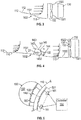
FIG. 1 is a perspective view of an aircraft; -
FIG. 2 is an axial view of a propulsor and a nozzle element of the aircraft ofFIG. 1 ; -
FIG. 3 is a side schematic view of a propulsor of an aircraft lacking a nozzle element; -
FIG. 4 is a side schematic view of the propulsor and the nozzle ofFIG. 2 ; and -
FIG. 5 is an axial view of the propulsor and the nozzle element of the aircraft ofFIG. 1 with nozzle element stowage and deployment capability. - These and other advantages and features will become more apparent from the following description taken in conjunction with the drawings.
- A detailed description of one or more embodiments of the disclosed apparatus and method are presented herein by way of exemplification and not limitation with reference to the Figures.
- As will be described below, a ram nozzle is placed in front of an inlet of a fan of an aircraft engine. The ram nozzle accelerates boundary layer airflows near a fuselage wall and slows other airflows that are more distant from the fuselage wall. The ram nozzle thus effectively provides for a more uniform inflow velocity of the airflows flowing into the inlet of the fan.
- With reference to
FIGS. 1 and 2 , anaircraft 101 is provided and includesfuselage 110. Thefuselage 110 has anose section 111, amain section 112 that is located aft of thenose section 111 and atail section 113 that is located aft of themain section 112. Theaircraft 101 also includesaerodynamic wings 114 extending outwardly from opposite sides of thefuselage 110 at themain section 112 and atail assembly 120 located at thetail section 113. Thetail assembly 120 has apylon 121 that extends vertically upwardly from thefuselage 110 andaerodynamic tail wings 122 extending outwardly from opposite sides of thepylon 121. Theaircraft 101 can further include controllable surfaces on theaerodynamic wings 114, thepylon 121 and theaerodynamic tail wings 122 that can be pivoted in order to facilitate the execution of controlled flight operations. - Power to drive ground-based and flight operations for the
aircraft 101 is generated withinengine nacelles 130. As shown inFIGS. 1 and4 , theengine nacelles 130 are supported at and partially embedded within arear portion 1130 of thetail section 113 although it is to be understood that this is not required and that theengine nacelles 130 can be supported at and partially embedded within other locations around theaircraft 101. In any case, eachengine nacelle 130 includes a boundary layer ingestion (BLI)propulsor 131 with aBLI propulsor inlet 132 and afan 133 disposed within theBLI propulsor inlet 132. - With continued reference to
FIGS. 1 and 2 and with additional reference toFIGS. 3 and 4 , theBLI propulsor inlet 132 has aninterior side 1321 and anexterior side 1322 and is disposed such that theinterior side 1321 is directly adjacent to thefuselage 110 at thetail section 113. At this location, airflows flowing around theaircraft 101 flow along thefuselage 110 during ground-based and flight operations such that the airflows flow past thenose section 111, then past themain section 112 and then past aforward portion 1131 of thetail section 113 before they enter theBLI propulsor inlet 132 as boundary layer airflows. - In accordance with embodiments, due to the curvature of the
fuselage 110 from themain section 112 to the tail section 113 (seeFIGS. 1 ,3 and 4 ), thefuselage 110 at themain section 112 at least partially obscures the span of thefan 133 at theinterior side 1321 of thepropulsor inlet 132 to the airflows flowing around the aircraft 101 (seeFIG. 2 ). A curvature 1132 (seeFIG. 4 ) of theforward portion 1131 of thetail section 113 curves inwardly toward theinterior side 1321 of thepropulsor inlet 132 to clear thefuselage 110 from the span of thefan 133 at theinterior side 1321 of theBLI propulsor inlet 132. - As shown in
FIG. 3 , in certain aircraft designs, viscous scrubbing of the airflows along thefuselage 110 and, to a lesser extent, thecurvature 1132 of theforward portion 1131 of thetail section 113 lead to boundary layer airflows closest to thefuselage 110 having reduced velocities as compared to the boundary layer airflows more distant from the fuselage 110 (in some or all cases, the viscous scrubbing has a substantially greater effect of the boundary layer airflows than the curvature 1132). These factors lead to a distortion of a profile of the boundary layer airflows. As a result, theBLI propulsor inlet 132 can receive non-uniform airflows and potential benefits of boundary layer airflow ingestion are reduced due to non-optimized angles of attack for thefan 133 and correspondingly decreased efficiencies. - In accordance with embodiments and, as shown in
FIGS. 1, 2 and4 , theaircraft 101 further includes anozzle element 140. Thenozzle element 140 is disposed at theforward portion 1131 of thetail section 113 upstream from theBLI propulsor inlet 132 and downstream from the location(s) of thefuselage 110 where the distortion of the boundary layer profile occurs. In this position, thenozzle element 140 is configured to homogenize the profile of the boundary layer airflows by accelerating those boundary layer airflows that flow toward theinterior side 1321 of theBLI propulsor inlet 132 and, in some cases, to decelerate those boundary layer airflows that flow toward theexterior side 1322 of theBLI propulsor inlet 132. TheBLI propulsor inlet 132 thus receives more uniform airflows and potential benefits of boundary layer airflow ingestion are restored, maintained or increased due to more optimized angles of attack for thefan 133 and correspondingly increased efficiencies. - As shown in
FIGS. 2 and4 , thenozzle element 140 has a step-wise curvature 141 (seeFIG. 3 ) toward theforward portion 1131 of thetail section 113 and has an annular curvature 142 (seeFIG. 2 ) about a longitudinal axis A (seeFIG. 1 ) of thefuselage 110. In greater detail, thenozzle element 140 includes aforward end 143, anaft end 144 and an intermediate section 145 that is interposed between theforward end 143 and theaft end 144. The intermediate section 145 includes aninward curvature 1451, which is connected with theforward end 143, and anoutward curvature 1452, which is connected with theaft end 144, to define the step-wise curvature 141. - The
nozzle element 140 extends axially along thefuselage 110 at thetail section 113 and has an axial curvature that generally mimics the tapering thefuselage 110 at thetail section 113. Nevertheless, theforward end 143 is separate from theforward portion 1131 of thetail section 113 by a first average distance D1, theaft end 144 is separate from theforward portion 1131 of thetail section 113 by a second average distance D2 and the first average distance D1 exceeds the second average distance D2. - With reference to
FIG. 2 and additional reference toFIG. 5 , one ormore vanes 150 extend outwardly from thefuselage 110 at thetail section 113 to support thenozzle element 140. With thesevanes 150, thenozzle element 140 can be deployed permanently or semi-permanently as shown inFIG. 2 or can be selectively deployable as shown inFIG. 5 . In the latter case, thenozzle element 140 can be stowed within anozzle element chamber 501 of thefuselage 110 at thetail section 113 and deployed in accordance with current aircraft or ground-based or flight operation conditions (i.e., when a BLI propulsor efficiency boost is desired from improved boundary layer airflow ingestion by theBLI propulsor inlet 132 resulting from the deployment of the nozzle element 140). - Selective deployment of the
nozzle element 140 can be executed by acontroller 160 that is coupled toservo elements 161. Theservo elements 161 are configured to position the one ormore vanes 150 such that thenozzle element 140 is stowed or deployed. Thecontroller 160 is configured to control the stowage and deployment of thenozzle element 140 in accordance with current aircraft or current ground-based or flight operation conditions. - Benefits of the features described herein are the provision of a ram nozzle that can simultaneously accelerate certain boundary layer airflows and decelerate the bulk of the fan inlet airflows to thereby provide for more uniform boundary layer ingestion at the BLI propulsor inlet, to allow a more optimized angle of attack and to provide for higher overall fan efficiency while retaining all of the propulsive efficiency benefits of boundary layer ingestion. These benefits will outweigh pressure losses due to the additional geometry of the ram nozzle.
- The term "about" is intended to include the degree of error associated with measurement of the particular quantity based upon the equipment available at the time of filing the application.
- The terminology used herein is for the purpose of describing particular embodiments only and is not intended to be limiting of the present disclosure. As used herein, the singular forms "a", "an" and "the" are intended to include the plural forms as well, unless the context clearly indicates otherwise. It will be further understood that the terms "comprises" and/or "comprising," when used in this specification, specify the presence of stated features, integers, steps, operations, elements, and/or components, but do not preclude the presence or addition of one or more other features, integers, steps, operations, element components, and/or groups thereof.
- While the present disclosure has been described with reference to an exemplary embodiment or embodiments, it will be understood by those skilled in the art that various changes may be made and equivalents may be substituted for elements thereof without departing from the scope of the present disclosure. In addition, many modifications may be made to adapt a particular situation or material to the teachings of the present disclosure without departing from the essential scope thereof. Therefore, it is intended that the present disclosure not be limited to the particular embodiment disclosed as the best mode contemplated for carrying out this present disclosure, but that the present disclosure will include all embodiments falling within the scope of the claims.
Claims (15)
- An aircraft (101), comprising:fuselage (110) having a nose (111), a main section (112) aft of the nose and a tail (113) aft of the main section;an engine nacelle (130) partially embedded in the tail and comprising a boundary layer ingestion (BLI) propulsor (131) with an inlet (132) directly adjacent to the fuselage; anda nozzle element (140) disposed upstream from the inlet and configured to accelerate boundary flows flowing toward an interior side (1321) of the engine nacelle.
- The aircraft according to claim 1, wherein the propulsor (131) comprises a fan (133) in the inlet.
- The aircraft according to claim 1 or 2, wherein the nozzle element has a step-wise curvature (141) and an annular curvature (142) about a longitudinal axis (A) of the fuselage.
- The aircraft according to claim 1, 2 or 3, wherein the nozzle element comprises:a forward end (143);an aft end (144); andan intermediate section (145) interposed between the forward and aft ends and comprising an inward curvature (1451) connected with the forward end and an outward curvature (1452) connected with the aft end,optionally wherein the forward end is separate from the fuselage by a first average distance (D1), the aft end is separate from the fuselage by a second average distance (D2) and the first average distance exceeds the second average distance.
- The aircraft according to any preceding claim, further comprising a vane (150) extending outwardly from the fuselage to support the nozzle element (140).
- The aircraft according to any preceding claim, wherein the nozzle element is selectively deployable, optionally wherein the nozzle element is stowable within a nozzle element chamber (501) of the fuselage.
- The aircraft according to claim 6, further comprising a controller (160) configured to deploy the nozzle element in accordance with current aircraft conditions.
- A system to promote boundary layer ingestion, the system comprising:a boundary layer ingestion (BLI) propulsor inlet (132);fuselage (110) along which airflows flow as boundary layer airflows toward the BLI propulsor inlet, the fuselage being configured to distort a profile of the boundary layer airflows; anda nozzle element (140) disposed upstream from the BLI propulsor inlet and downstream from a distortion of the boundary layer airflows by the fuselage and configured to homogenize the profile of the boundary layer airflows.
- The system according to claim 8, wherein the BLI propulsor inlet comprises a fan (133).
- The system according to claim 8 or 9, wherein the nozzle element has a step-wise curvature (141) and an annular curvature (142) about a longitudinal axis (A) of the fuselage.
- The system according to claim 8, 9 or 10, wherein the nozzle element comprises:a forward end (143);an aft end (144); andan intermediate section (145) interposed between the forward and aft ends and comprising an inward curvature (1451) connected with the forward end and an outward curvature (1452) connected with the aft end,optionally wherein the forward end is separate from the fuselage by a first average distance (D1), the aft end is separate from the fuselage by a second average distance (D2) and the first average distance exceeds the second average distance.
- The system according to any of claims 8 to 11, further comprising a vane (150) extending outwardly from the fuselage to support the nozzle element.
- The system according to any of claims 8 to 12, wherein the nozzle element (140) is selectively deployable,
optionally wherein the nozzle element is stowable within a nozzle element chamber (501) of the curved section (145), and
optionally further comprising a controller (160) configured to deploy the nozzle element in accordance with current aircraft conditions. - The system according to any of claims 8 to 13, wherein the boundary layer ingestion (BLI) propulsor inlet (132) comprises interior (1321) and exterior (1322) sides;
wherein the airflows flow as boundary layer airflows toward the interior and exterior sides of the BLI propulsor inlet; and
wherein the nozzle element (140) is configured to homogenize the profile of the boundary layer airflows by accelerating the airflows flowing as boundary layer airflows toward the interior side (1321) of the BLI propulsor inlet and decelerating the airflows flowing as boundary layer airflows toward the exterior side (1322) of the BLI propulsor inlet. - An aircraft comprising the system of any of claims 8 to 14.
Applications Claiming Priority (1)
| Application Number | Priority Date | Filing Date | Title |
|---|---|---|---|
| US16/219,423 US11124291B2 (en) | 2018-12-13 | 2018-12-13 | System to promote accelerated boundary layer ingestion |
Publications (2)
| Publication Number | Publication Date |
|---|---|
| EP3666644A1 true EP3666644A1 (en) | 2020-06-17 |
| EP3666644B1 EP3666644B1 (en) | 2022-03-16 |
Family
ID=68916412
Family Applications (1)
| Application Number | Title | Priority Date | Filing Date |
|---|---|---|---|
| EP19216036.4A Active EP3666644B1 (en) | 2018-12-13 | 2019-12-13 | System to promote accelerated boundary layer ingestion |
Country Status (2)
| Country | Link |
|---|---|
| US (1) | US11124291B2 (en) |
| EP (1) | EP3666644B1 (en) |
Families Citing this family (4)
| Publication number | Priority date | Publication date | Assignee | Title |
|---|---|---|---|---|
| FR3098790B1 (en) * | 2019-07-17 | 2024-03-15 | Safran Aircraft Engines | Improved boundary layer ingestion propulsion assembly |
| JP7603547B2 (en) * | 2021-07-26 | 2024-12-20 | 三菱重工業株式会社 | aircraft |
| JP7822023B2 (en) * | 2021-10-26 | 2026-03-02 | 国立研究開発法人宇宙航空研究開発機構 | Aircraft and BLI Promotion Department |
| US12600454B2 (en) | 2024-09-06 | 2026-04-14 | Rtx Corporation | Inlet vane forward of aircraft propulsion system airflow inlet |
Citations (4)
| Publication number | Priority date | Publication date | Assignee | Title |
|---|---|---|---|---|
| US20180016000A1 (en) * | 2016-07-13 | 2018-01-18 | Nikolai N. Pastouchenko | Aircraft having an airflow duct |
| US20180051716A1 (en) * | 2016-08-19 | 2018-02-22 | General Electric Company | Thermal management system for an electric propulsion engine |
| EP3333403A1 (en) * | 2016-12-07 | 2018-06-13 | United Technologies Corporation | Boundary layer excitation aft fan gas turbine engine |
| EP3415437A1 (en) * | 2017-06-12 | 2018-12-19 | United Technologies Corporation | Aft fan counter-rotating turbine engine |
Family Cites Families (9)
| Publication number | Priority date | Publication date | Assignee | Title |
|---|---|---|---|---|
| US6527224B2 (en) | 2001-03-23 | 2003-03-04 | The Boeing Company | Separate boundary layer engine inlet |
| US7861968B2 (en) * | 2006-10-26 | 2011-01-04 | The Boeing Company | Air inlet and method for a highspeed mobile platform |
| US7665689B2 (en) | 2006-11-24 | 2010-02-23 | The Boeing Company | Unconventional integrated propulsion systems and methods for blended wing body aircraft |
| US8511603B2 (en) * | 2009-01-14 | 2013-08-20 | Lewis E. Blomeley | Roadable aircraft with collapsible wings and ductless fan |
| DE102010023938A1 (en) * | 2010-06-16 | 2011-12-22 | Eads Deutschland Gmbh | Driven aircraft, in particular as a flying wing and / or with a low radar signature trained aircraft |
| GB201117079D0 (en) * | 2011-10-05 | 2011-11-16 | Rolls Royce Plc | A propulsive unit for an aircraft |
| FR3039227B1 (en) | 2015-07-22 | 2019-12-27 | Safran Aircraft Engines | AIRCRAFT COMPRISING A CARENE REAR PROPELLER WITH MOBILE SHUTTERS INPUT STATOR |
| US10464668B2 (en) * | 2015-09-02 | 2019-11-05 | Jetoptera, Inc. | Configuration for vertical take-off and landing system for aerial vehicles |
| US10399670B2 (en) * | 2016-09-26 | 2019-09-03 | General Electric Company | Aircraft having an aft engine and internal flow passages |
-
2018
- 2018-12-13 US US16/219,423 patent/US11124291B2/en active Active
-
2019
- 2019-12-13 EP EP19216036.4A patent/EP3666644B1/en active Active
Patent Citations (4)
| Publication number | Priority date | Publication date | Assignee | Title |
|---|---|---|---|---|
| US20180016000A1 (en) * | 2016-07-13 | 2018-01-18 | Nikolai N. Pastouchenko | Aircraft having an airflow duct |
| US20180051716A1 (en) * | 2016-08-19 | 2018-02-22 | General Electric Company | Thermal management system for an electric propulsion engine |
| EP3333403A1 (en) * | 2016-12-07 | 2018-06-13 | United Technologies Corporation | Boundary layer excitation aft fan gas turbine engine |
| EP3415437A1 (en) * | 2017-06-12 | 2018-12-19 | United Technologies Corporation | Aft fan counter-rotating turbine engine |
Also Published As
| Publication number | Publication date |
|---|---|
| US20200189724A1 (en) | 2020-06-18 |
| US11124291B2 (en) | 2021-09-21 |
| EP3666644B1 (en) | 2022-03-16 |
Similar Documents
| Publication | Publication Date | Title |
|---|---|---|
| EP3666644B1 (en) | System to promote accelerated boundary layer ingestion | |
| KR102668106B1 (en) | Ejector and airfoil structure | |
| CN109421920B (en) | Aircraft propulsion system and method | |
| EP3505450B1 (en) | Apparatus to vary an air intake of aircraft engines | |
| AU2020268690B2 (en) | Fluidic propulsive system | |
| CN106986036A (en) | Rear engine nacelle shape for aircraft | |
| CN103917444B (en) | Connection hanger for turbine engine | |
| CN106542101A (en) | Non-axis symmetry rear engine | |
| CN106986038A (en) | Aircraft with rear engine | |
| EP3653513B1 (en) | Boundary layer ingestion fan system | |
| CN108327915A (en) | Cabin for aircraft rear fan | |
| JP2019085097A (en) | Fan cowl with serrated trailing edge providing attached flow in reverse thrust mode | |
| EP2995553A1 (en) | Air generation unit for an aircraft and method for its operation | |
| US20170313412A1 (en) | Device for reducing aerodynamic disturbances in the wake of an aerodynamic profile by variable-distribution blowing on the top side and the underside | |
| EP3653508A1 (en) | Boundary layer ingestion fan system | |
| US5480110A (en) | Transport plane with stub tail | |
| EP2848522A1 (en) | Unsteady aerodynamics mitigation for multi-body aerospace apparatus | |
| EP3653509B1 (en) | Boundary layer ingestion fan system | |
| CN110015432A (en) | Engine nacelle for aircraft | |
| EP3653511A1 (en) | Boundary layer ingestion fan system | |
| EP4650588A2 (en) | Combination compressed-fluid ejector and propeller propulsion system | |
| US20190023409A1 (en) | System for preventing exhaust gas impingement on aircraft surfaces and surrounding areas | |
| EP3653510B1 (en) | Boundary layer ingestion fan system | |
| EP3653512B1 (en) | Boundary layer ingestion fan system | |
| EP3653507A1 (en) | Boundary layer ingestion fan system |
Legal Events
| Date | Code | Title | Description |
|---|---|---|---|
| PUAI | Public reference made under article 153(3) epc to a published international application that has entered the european phase |
Free format text: ORIGINAL CODE: 0009012 |
|
| STAA | Information on the status of an ep patent application or granted ep patent |
Free format text: STATUS: THE APPLICATION HAS BEEN PUBLISHED |
|
| AK | Designated contracting states |
Kind code of ref document: A1 Designated state(s): AL AT BE BG CH CY CZ DE DK EE ES FI FR GB GR HR HU IE IS IT LI LT LU LV MC MK MT NL NO PL PT RO RS SE SI SK SM TR |
|
| AX | Request for extension of the european patent |
Extension state: BA ME |
|
| STAA | Information on the status of an ep patent application or granted ep patent |
Free format text: STATUS: REQUEST FOR EXAMINATION WAS MADE |
|
| 17P | Request for examination filed |
Effective date: 20201217 |
|
| RBV | Designated contracting states (corrected) |
Designated state(s): AL AT BE BG CH CY CZ DE DK EE ES FI FR GB GR HR HU IE IS IT LI LT LU LV MC MK MT NL NO PL PT RO RS SE SI SK SM TR |
|
| RAP1 | Party data changed (applicant data changed or rights of an application transferred) |
Owner name: RAYTHEON TECHNOLOGIES CORPORATION |
|
| GRAP | Despatch of communication of intention to grant a patent |
Free format text: ORIGINAL CODE: EPIDOSNIGR1 |
|
| STAA | Information on the status of an ep patent application or granted ep patent |
Free format text: STATUS: GRANT OF PATENT IS INTENDED |
|
| RIC1 | Information provided on ipc code assigned before grant |
Ipc: B64C 21/02 20060101AFI20210427BHEP Ipc: B64D 33/02 20060101ALN20210427BHEP |
|
| RIC1 | Information provided on ipc code assigned before grant |
Ipc: B64C 21/02 20060101AFI20210430BHEP Ipc: B64D 33/02 20060101ALN20210430BHEP |
|
| INTG | Intention to grant announced |
Effective date: 20210519 |
|
| GRAJ | Information related to disapproval of communication of intention to grant by the applicant or resumption of examination proceedings by the epo deleted |
Free format text: ORIGINAL CODE: EPIDOSDIGR1 |
|
| STAA | Information on the status of an ep patent application or granted ep patent |
Free format text: STATUS: REQUEST FOR EXAMINATION WAS MADE |
|
| GRAP | Despatch of communication of intention to grant a patent |
Free format text: ORIGINAL CODE: EPIDOSNIGR1 |
|
| STAA | Information on the status of an ep patent application or granted ep patent |
Free format text: STATUS: GRANT OF PATENT IS INTENDED |
|
| INTC | Intention to grant announced (deleted) | ||
| RIC1 | Information provided on ipc code assigned before grant |
Ipc: B64D 33/02 20060101ALN20210909BHEP Ipc: B64C 21/02 20060101AFI20210909BHEP |
|
| INTG | Intention to grant announced |
Effective date: 20211004 |
|
| GRAS | Grant fee paid |
Free format text: ORIGINAL CODE: EPIDOSNIGR3 |
|
| GRAA | (expected) grant |
Free format text: ORIGINAL CODE: 0009210 |
|
| STAA | Information on the status of an ep patent application or granted ep patent |
Free format text: STATUS: THE PATENT HAS BEEN GRANTED |
|
| AK | Designated contracting states |
Kind code of ref document: B1 Designated state(s): AL AT BE BG CH CY CZ DE DK EE ES FI FR GB GR HR HU IE IS IT LI LT LU LV MC MK MT NL NO PL PT RO RS SE SI SK SM TR |
|
| REG | Reference to a national code |
Ref country code: GB Ref legal event code: FG4D |
|
| REG | Reference to a national code |
Ref country code: CH Ref legal event code: EP |
|
| REG | Reference to a national code |
Ref country code: DE Ref legal event code: R096 Ref document number: 602019012580 Country of ref document: DE |
|
| REG | Reference to a national code |
Ref country code: IE Ref legal event code: FG4D |
|
| REG | Reference to a national code |
Ref country code: AT Ref legal event code: REF Ref document number: 1475704 Country of ref document: AT Kind code of ref document: T Effective date: 20220415 |
|
| REG | Reference to a national code |
Ref country code: LT Ref legal event code: MG9D |
|
| REG | Reference to a national code |
Ref country code: NL Ref legal event code: MP Effective date: 20220316 |
|
| PG25 | Lapsed in a contracting state [announced via postgrant information from national office to epo] |
Ref country code: SE Free format text: LAPSE BECAUSE OF FAILURE TO SUBMIT A TRANSLATION OF THE DESCRIPTION OR TO PAY THE FEE WITHIN THE PRESCRIBED TIME-LIMIT Effective date: 20220316 Ref country code: RS Free format text: LAPSE BECAUSE OF FAILURE TO SUBMIT A TRANSLATION OF THE DESCRIPTION OR TO PAY THE FEE WITHIN THE PRESCRIBED TIME-LIMIT Effective date: 20220316 Ref country code: NO Free format text: LAPSE BECAUSE OF FAILURE TO SUBMIT A TRANSLATION OF THE DESCRIPTION OR TO PAY THE FEE WITHIN THE PRESCRIBED TIME-LIMIT Effective date: 20220616 Ref country code: LT Free format text: LAPSE BECAUSE OF FAILURE TO SUBMIT A TRANSLATION OF THE DESCRIPTION OR TO PAY THE FEE WITHIN THE PRESCRIBED TIME-LIMIT Effective date: 20220316 Ref country code: HR Free format text: LAPSE BECAUSE OF FAILURE TO SUBMIT A TRANSLATION OF THE DESCRIPTION OR TO PAY THE FEE WITHIN THE PRESCRIBED TIME-LIMIT Effective date: 20220316 Ref country code: BG Free format text: LAPSE BECAUSE OF FAILURE TO SUBMIT A TRANSLATION OF THE DESCRIPTION OR TO PAY THE FEE WITHIN THE PRESCRIBED TIME-LIMIT Effective date: 20220616 |
|
| REG | Reference to a national code |
Ref country code: AT Ref legal event code: MK05 Ref document number: 1475704 Country of ref document: AT Kind code of ref document: T Effective date: 20220316 |
|
| PG25 | Lapsed in a contracting state [announced via postgrant information from national office to epo] |
Ref country code: LV Free format text: LAPSE BECAUSE OF FAILURE TO SUBMIT A TRANSLATION OF THE DESCRIPTION OR TO PAY THE FEE WITHIN THE PRESCRIBED TIME-LIMIT Effective date: 20220316 Ref country code: GR Free format text: LAPSE BECAUSE OF FAILURE TO SUBMIT A TRANSLATION OF THE DESCRIPTION OR TO PAY THE FEE WITHIN THE PRESCRIBED TIME-LIMIT Effective date: 20220617 Ref country code: FI Free format text: LAPSE BECAUSE OF FAILURE TO SUBMIT A TRANSLATION OF THE DESCRIPTION OR TO PAY THE FEE WITHIN THE PRESCRIBED TIME-LIMIT Effective date: 20220316 |
|
| PG25 | Lapsed in a contracting state [announced via postgrant information from national office to epo] |
Ref country code: NL Free format text: LAPSE BECAUSE OF FAILURE TO SUBMIT A TRANSLATION OF THE DESCRIPTION OR TO PAY THE FEE WITHIN THE PRESCRIBED TIME-LIMIT Effective date: 20220316 |
|
| PG25 | Lapsed in a contracting state [announced via postgrant information from national office to epo] |
Ref country code: SM Free format text: LAPSE BECAUSE OF FAILURE TO SUBMIT A TRANSLATION OF THE DESCRIPTION OR TO PAY THE FEE WITHIN THE PRESCRIBED TIME-LIMIT Effective date: 20220316 Ref country code: SK Free format text: LAPSE BECAUSE OF FAILURE TO SUBMIT A TRANSLATION OF THE DESCRIPTION OR TO PAY THE FEE WITHIN THE PRESCRIBED TIME-LIMIT Effective date: 20220316 Ref country code: RO Free format text: LAPSE BECAUSE OF FAILURE TO SUBMIT A TRANSLATION OF THE DESCRIPTION OR TO PAY THE FEE WITHIN THE PRESCRIBED TIME-LIMIT Effective date: 20220316 Ref country code: PT Free format text: LAPSE BECAUSE OF FAILURE TO SUBMIT A TRANSLATION OF THE DESCRIPTION OR TO PAY THE FEE WITHIN THE PRESCRIBED TIME-LIMIT Effective date: 20220718 Ref country code: ES Free format text: LAPSE BECAUSE OF FAILURE TO SUBMIT A TRANSLATION OF THE DESCRIPTION OR TO PAY THE FEE WITHIN THE PRESCRIBED TIME-LIMIT Effective date: 20220316 Ref country code: EE Free format text: LAPSE BECAUSE OF FAILURE TO SUBMIT A TRANSLATION OF THE DESCRIPTION OR TO PAY THE FEE WITHIN THE PRESCRIBED TIME-LIMIT Effective date: 20220316 Ref country code: CZ Free format text: LAPSE BECAUSE OF FAILURE TO SUBMIT A TRANSLATION OF THE DESCRIPTION OR TO PAY THE FEE WITHIN THE PRESCRIBED TIME-LIMIT Effective date: 20220316 Ref country code: AT Free format text: LAPSE BECAUSE OF FAILURE TO SUBMIT A TRANSLATION OF THE DESCRIPTION OR TO PAY THE FEE WITHIN THE PRESCRIBED TIME-LIMIT Effective date: 20220316 |
|
| PG25 | Lapsed in a contracting state [announced via postgrant information from national office to epo] |
Ref country code: PL Free format text: LAPSE BECAUSE OF FAILURE TO SUBMIT A TRANSLATION OF THE DESCRIPTION OR TO PAY THE FEE WITHIN THE PRESCRIBED TIME-LIMIT Effective date: 20220316 Ref country code: IS Free format text: LAPSE BECAUSE OF FAILURE TO SUBMIT A TRANSLATION OF THE DESCRIPTION OR TO PAY THE FEE WITHIN THE PRESCRIBED TIME-LIMIT Effective date: 20220716 Ref country code: AL Free format text: LAPSE BECAUSE OF FAILURE TO SUBMIT A TRANSLATION OF THE DESCRIPTION OR TO PAY THE FEE WITHIN THE PRESCRIBED TIME-LIMIT Effective date: 20220316 |
|
| REG | Reference to a national code |
Ref country code: DE Ref legal event code: R097 Ref document number: 602019012580 Country of ref document: DE |
|
| PLBE | No opposition filed within time limit |
Free format text: ORIGINAL CODE: 0009261 |
|
| STAA | Information on the status of an ep patent application or granted ep patent |
Free format text: STATUS: NO OPPOSITION FILED WITHIN TIME LIMIT |
|
| PG25 | Lapsed in a contracting state [announced via postgrant information from national office to epo] |
Ref country code: DK Free format text: LAPSE BECAUSE OF FAILURE TO SUBMIT A TRANSLATION OF THE DESCRIPTION OR TO PAY THE FEE WITHIN THE PRESCRIBED TIME-LIMIT Effective date: 20220316 |
|
| 26N | No opposition filed |
Effective date: 20221219 |
|
| PG25 | Lapsed in a contracting state [announced via postgrant information from national office to epo] |
Ref country code: SI Free format text: LAPSE BECAUSE OF FAILURE TO SUBMIT A TRANSLATION OF THE DESCRIPTION OR TO PAY THE FEE WITHIN THE PRESCRIBED TIME-LIMIT Effective date: 20220316 |
|
| P01 | Opt-out of the competence of the unified patent court (upc) registered |
Effective date: 20230521 |
|
| PG25 | Lapsed in a contracting state [announced via postgrant information from national office to epo] |
Ref country code: IT Free format text: LAPSE BECAUSE OF FAILURE TO SUBMIT A TRANSLATION OF THE DESCRIPTION OR TO PAY THE FEE WITHIN THE PRESCRIBED TIME-LIMIT Effective date: 20220316 |
|
| REG | Reference to a national code |
Ref country code: CH Ref legal event code: PL |
|
| REG | Reference to a national code |
Ref country code: BE Ref legal event code: MM Effective date: 20221231 |
|
| PG25 | Lapsed in a contracting state [announced via postgrant information from national office to epo] |
Ref country code: LU Free format text: LAPSE BECAUSE OF NON-PAYMENT OF DUE FEES Effective date: 20221213 |
|
| PG25 | Lapsed in a contracting state [announced via postgrant information from national office to epo] |
Ref country code: LI Free format text: LAPSE BECAUSE OF NON-PAYMENT OF DUE FEES Effective date: 20221231 Ref country code: IE Free format text: LAPSE BECAUSE OF NON-PAYMENT OF DUE FEES Effective date: 20221213 Ref country code: CH Free format text: LAPSE BECAUSE OF NON-PAYMENT OF DUE FEES Effective date: 20221231 |
|
| PG25 | Lapsed in a contracting state [announced via postgrant information from national office to epo] |
Ref country code: BE Free format text: LAPSE BECAUSE OF NON-PAYMENT OF DUE FEES Effective date: 20221231 |
|
| PG25 | Lapsed in a contracting state [announced via postgrant information from national office to epo] |
Ref country code: HU Free format text: LAPSE BECAUSE OF FAILURE TO SUBMIT A TRANSLATION OF THE DESCRIPTION OR TO PAY THE FEE WITHIN THE PRESCRIBED TIME-LIMIT; INVALID AB INITIO Effective date: 20191213 |
|
| PG25 | Lapsed in a contracting state [announced via postgrant information from national office to epo] |
Ref country code: CY Free format text: LAPSE BECAUSE OF FAILURE TO SUBMIT A TRANSLATION OF THE DESCRIPTION OR TO PAY THE FEE WITHIN THE PRESCRIBED TIME-LIMIT Effective date: 20220316 |
|
| PG25 | Lapsed in a contracting state [announced via postgrant information from national office to epo] |
Ref country code: MK Free format text: LAPSE BECAUSE OF FAILURE TO SUBMIT A TRANSLATION OF THE DESCRIPTION OR TO PAY THE FEE WITHIN THE PRESCRIBED TIME-LIMIT Effective date: 20220316 |
|
| PG25 | Lapsed in a contracting state [announced via postgrant information from national office to epo] |
Ref country code: MC Free format text: LAPSE BECAUSE OF FAILURE TO SUBMIT A TRANSLATION OF THE DESCRIPTION OR TO PAY THE FEE WITHIN THE PRESCRIBED TIME-LIMIT Effective date: 20220316 |
|
| PG25 | Lapsed in a contracting state [announced via postgrant information from national office to epo] |
Ref country code: TR Free format text: LAPSE BECAUSE OF FAILURE TO SUBMIT A TRANSLATION OF THE DESCRIPTION OR TO PAY THE FEE WITHIN THE PRESCRIBED TIME-LIMIT Effective date: 20220316 Ref country code: MC Free format text: LAPSE BECAUSE OF FAILURE TO SUBMIT A TRANSLATION OF THE DESCRIPTION OR TO PAY THE FEE WITHIN THE PRESCRIBED TIME-LIMIT Effective date: 20220316 |
|
| PG25 | Lapsed in a contracting state [announced via postgrant information from national office to epo] |
Ref country code: MT Free format text: LAPSE BECAUSE OF FAILURE TO SUBMIT A TRANSLATION OF THE DESCRIPTION OR TO PAY THE FEE WITHIN THE PRESCRIBED TIME-LIMIT Effective date: 20220316 |
|
| REG | Reference to a national code |
Ref country code: DE Ref legal event code: R081 Ref document number: 602019012580 Country of ref document: DE Owner name: RTX CORPORATION (N.D.GES.D. STAATES DELAWARE),, US Free format text: FORMER OWNER: RAYTHEON TECHNOLOGIES CORPORATION, FARMINGTON, CT, US |
|
| PGFP | Annual fee paid to national office [announced via postgrant information from national office to epo] |
Ref country code: DE Payment date: 20251126 Year of fee payment: 7 |
|
| PGFP | Annual fee paid to national office [announced via postgrant information from national office to epo] |
Ref country code: GB Payment date: 20251120 Year of fee payment: 7 |
|
| PGFP | Annual fee paid to national office [announced via postgrant information from national office to epo] |
Ref country code: FR Payment date: 20251120 Year of fee payment: 7 |