EP3666641A1 - Foreign object impact proof windshield assembly - Google Patents
Foreign object impact proof windshield assembly Download PDFInfo
- Publication number
- EP3666641A1 EP3666641A1 EP18400036.2A EP18400036A EP3666641A1 EP 3666641 A1 EP3666641 A1 EP 3666641A1 EP 18400036 A EP18400036 A EP 18400036A EP 3666641 A1 EP3666641 A1 EP 3666641A1
- Authority
- EP
- European Patent Office
- Prior art keywords
- windshield
- flexible element
- vehicle frame
- vehicle
- impact
- Prior art date
- Legal status (The legal status is an assumption and is not a legal conclusion. Google has not performed a legal analysis and makes no representation as to the accuracy of the status listed.)
- Granted
Links
Images



Classifications
-
- B—PERFORMING OPERATIONS; TRANSPORTING
- B64—AIRCRAFT; AVIATION; COSMONAUTICS
- B64C—AEROPLANES; HELICOPTERS
- B64C1/00—Fuselages; Constructional features common to fuselages, wings, stabilising surfaces or the like
- B64C1/14—Windows; Doors; Hatch covers or access panels; Surrounding frame structures; Canopies; Windscreens accessories therefor, e.g. pressure sensors, water deflectors, hinges, seals, handles, latches, windscreen wipers
- B64C1/1476—Canopies; Windscreens or similar transparent elements
- B64C1/1484—Windows
-
- B—PERFORMING OPERATIONS; TRANSPORTING
- B60—VEHICLES IN GENERAL
- B60J—WINDOWS, WINDSCREENS, NON-FIXED ROOFS, DOORS, OR SIMILAR DEVICES FOR VEHICLES; REMOVABLE EXTERNAL PROTECTIVE COVERINGS SPECIALLY ADAPTED FOR VEHICLES
- B60J1/00—Windows; Windscreens; Accessories therefor
- B60J1/004—Mounting of windows
- B60J1/006—Mounting of windows characterised by fixation means such as clips, adhesive, etc.
-
- B—PERFORMING OPERATIONS; TRANSPORTING
- B60—VEHICLES IN GENERAL
- B60J—WINDOWS, WINDSCREENS, NON-FIXED ROOFS, DOORS, OR SIMILAR DEVICES FOR VEHICLES; REMOVABLE EXTERNAL PROTECTIVE COVERINGS SPECIALLY ADAPTED FOR VEHICLES
- B60J1/00—Windows; Windscreens; Accessories therefor
- B60J1/20—Accessories, e.g. wind deflectors, blinds
- B60J1/2094—Protective means for window, e.g. additional panel or foil, against vandalism, dirt, wear, shattered glass, etc.
-
- B—PERFORMING OPERATIONS; TRANSPORTING
- B64—AIRCRAFT; AVIATION; COSMONAUTICS
- B64C—AEROPLANES; HELICOPTERS
- B64C1/00—Fuselages; Constructional features common to fuselages, wings, stabilising surfaces or the like
- B64C1/14—Windows; Doors; Hatch covers or access panels; Surrounding frame structures; Canopies; Windscreens accessories therefor, e.g. pressure sensors, water deflectors, hinges, seals, handles, latches, windscreen wipers
- B64C1/1476—Canopies; Windscreens or similar transparent elements
- B64C1/1492—Structure and mounting of the transparent elements in the window or windscreen
-
- B—PERFORMING OPERATIONS; TRANSPORTING
- B60—VEHICLES IN GENERAL
- B60R—VEHICLES, VEHICLE FITTINGS, OR VEHICLE PARTS, NOT OTHERWISE PROVIDED FOR
- B60R21/00—Arrangements or fittings on vehicles for protecting or preventing injuries to occupants or pedestrians in case of accidents or other traffic risks
- B60R21/34—Protecting non-occupants of a vehicle, e.g. pedestrians
- B60R2021/343—Protecting non-occupants of a vehicle, e.g. pedestrians using deformable body panel, bodywork or components
Definitions
- the invention is related to a vehicle with a vehicle frame and a windshield assembly that is mounted to the vehicle frame, the windshield assembly comprising at least one windshield and at least one flexible element.
- Vehicle frames can be provided with one or more windshields that are configured to embody aerodynamically formed windows e. g. on a given front of corresponding vehicles.
- the windshields are provided in order to protect occupants of the corresponding vehicles from wind and potentially flying debris, such as insects and dust.
- the windshield can e. g. be mounted to an associated vehicle frame via a mounting structure.
- a mounting structure does not only allow for a quick and easy exchange of a damaged or broken windshield, but also enables a required compatibility between the associated vehicle frame and specific material properties of the windshield, as well as a transfer of loads between the windshield and the associated vehicle frame in operation of an underlying vehicle.
- the maximum applicable load requirements are very high if the helicopter has a maximum takeoff weight of more than 3.175 kg, as the windshield of such a helicopter must be able to sustain a foreign object impact, such as e. g. a bird strike.
- a minimum available area of visibility for a pilot of the helicopter must be provided and, thus, represents an important geometric constraint for the design of the windshield and associated mounting means, such as an associated mounting structure.
- windshields with many different materials and configurations are known from the prior art.
- One such windshield is a polycarbonate windshield which is considerably lighter than the conventional wide spread multilayer foreign object impact proof windshields.
- a polycarbonate windshield advantageously offers a higher degree of freedom than the wide spread multilayer foreign object impact proof windshields with respect to an underlying geometry of the windshield, and in particular its curvature.
- An exemplary vehicle with a polycarbonate windshield is described hereinafter.
- the windshield mounting assembly comprises a mounting frame that is attached to a windshield and adapted for mounting the windshield to the associated vehicle frame.
- the mounting frame comprises at least one fastener receiving opening that is provided to receive associated frame fasteners and a bonding interface arranged between the windshield and the mounting frame. Very high loads can be transferred from the mounting frame via the frame fasteners to the vehicle frame.
- the windshield can be made of any transparent material including glass and polymers, such as e. g. polymethyl methacrylate and polycarbonate.
- polycarbonate as a selected windshield material, as polycarbonate is a highly resistant material but has to face some challenges. More specifically, polycarbonate is generally ductile but can brittle suddenly depending on a respective strain rate. In fact, a three-dimensional stress state with high strains can lead to a sudden brittle failure of a polycarbonate windshield without absorbing a lot of energy. Furthermore, polycarbonate windshields are extremely sensitive to notches and bored holes. Moreover, cold temperatures also have a negative impact on an underlying failure behavior of polycarbonate windshields.
- Another aspect that must be considered in the development of windshield mounting assemblies consists in the capability of the windshield mounting assemblies to absorb energy in case of an impact on a respective windshield, such as a foreign object impact.
- This aspect is particularly relevant in the automotive industry and exemplary energy absorbing structures are described in the following documents: EP 3 056 412 A1 , EP 1 518 780 A1 , DE 19 921 871 A1 , WO 2015/152096 A1 , DE 10 2011 081 784 A1 , JP 2008100533 A , and US 6,193,304 B1 .
- These documents respectively describe an energy absorbing structure or cowl that takes loads by compression via respective windshields. More specifically, the purpose of these energy absorbing structures is to protect pedestrians from hitting structural members of respective automobiles.
- document US 6,193,304 B1 describes a windshield support of an automobile that is formed as a cantilever-like or overhang support including a bend portion, a box portion and a flange portion which are formed continuously in that order.
- the bend portion is extended from an instrument panel upper portion and has a substantially V-shaped cross section.
- the box portion has a hollow rectangular cross section and is sufficiently disposed away from the instrument panel upper portion.
- the flange portion receives a windshield.
- a recessed portion is provided at the instrument panel upper portion for receiving a lower portion of the box portion when the bend portion has to be bent by virtue of an external force applied to the windshield.
- the bend portion absorbs loads that occur e. g. as a result of foreign object impacts on the windshield.
- the degree of freedom of the bend portion is only translational, and no rotational freedom is provided.
- an object of the present invention to provide a vehicle that overcomes the above-described drawbacks and that is provided with an improved windshield assembly that is suitable to absorb at least partially loads resulting from an impact on an associated windshield, in particular resulting from a foreign object impact, such as a bird strike.
- a vehicle comprising a windshield assembly mounted to a vehicle frame and comprising at least one flexible element, said vehicle comprising the features of claim 1.
- a vehicle with a vehicle frame and a windshield assembly is provided.
- the windshield assembly is mounted to the vehicle frame and closes an associated opening provided in the vehicle frame.
- the windshield assembly comprises at least one flexible element and at least one windshield.
- the at least one flexible element is attached to the at least one windshield and connects the at least one windshield to the vehicle frame for at least partially absorbing loads resulting from an impact on the at least one windshield, in particular resulting from a foreign object impact.
- the at least one flexible element connects the at least one windshield to the vehicle frame such that the at least one windshield pivots relative to the vehicle frame by means of the at least one flexible element upon occurrence of an impact on the at least one windshield such that the at least one flexible element defines a hinge element.
- the term "flexible” used in the expression “flexible element” should be understood such that reference is made to an element that may at least be flexed. More specifically, the flexible element may at least be plastically deformable. Preferably, the flexible element is at least within predetermined tolerances non-destructively plastically deformable. Furthermore, or alternatively, the flexible element may be elastically deformable within a predetermined range or degree of flexure.
- the flexible element permits to transfer loads from the windshield to the cabin frame. More particularly, the flexible element permits to reduce loads on the windshield, which occur in response to an impact on the windshield, in particular resulting from a foreign object impact such as a bird strike. By reducing the loads on the windshield, breakage of the windshield may at least in a wide range be restricted to excessive load cases.
- the flexible element may be implemented as an energy absorbing element.
- such an implementation is not mandatory, as the main function of the flexible element consists in the load transfer to the vehicle frame.
- the flexible element permits to relieve the windshield, but also the vehicle frame.
- the windshield advantageously bends three-dimensionally towards a respective vehicle interior and, thereby, the flexible element to which the windshield is attached follows the movement of the windshield and preferably deforms plastically.
- the windshield bends first inwardly, and, because of its flexibility, then back outwardly without breaking.
- the flexible element follows the movement and thereby absorbs the impact energy of the foreign object impact so that the vehicle frame will not be damaged.
- the at least one flexible element can barely transmit a moment. Therefore, the inventive windshield assembly does not transfer a respective peeling load to the cabin frame.
- the inventive windshield assembly can be applied to a wide range of vehicles including, but not being limited to, helicopters, aircrafts, cars, and vessels. Furthermore, as the inventive windshield assembly is attached to an associated vehicle frame, the windshield assembly can easily be replaced if necessary. Moreover, the inventive windshield assembly does not interfere with an underlying required area of visibility and is more compact compared to conventional mounting frame designs.
- the at least one windshield of the inventive windshield assembly is provided with an outer circumference that is smaller than or equal to an inner circumference of the associated opening of the vehicle frame such that the at least one windshield is arranged on the vehicle without overlapping the vehicle frame.
- the at least one windshield may overlap the vehicle frame in a respective overlap region without being attached to the at least one flexible element and/or the vehicle frame in the respective overlap region.
- the at least one flexible element is a plate-type element with an inner opening.
- plate-type refers in the context of the present invention to an at least essentially flat structure that may have a slight curvature.
- a flat structure may be obtained from a sheet metal.
- the inner opening has a circumference that is smaller than an outer circumference of the at least one windshield.
- the at least one flexible element has an outer circumference that is greater than an inner circumference of the associated opening of the vehicle frame.
- the at least one flexible element comprises a fiber reinforced polymer and/or metal.
- the at least one flexible element is bonded to the vehicle frame by means of at least one adhesive layer.
- the at least one flexible element is attached to the vehicle frame by means of at least one fastener.
- the fasteners may be embodied as screws, bolts or rivets.
- the at least one windshield is bonded to the at least one flexible element by means of at least one adhesive layer.
- the use of an adhesive layer reduces weight and complexity of the windshield assembly. Furthermore, notches which might trigger a brittle failure may at least be reduced or even completely avoided.
- an additional adhesive layer may add softness to the windshield assembly.
- the respective two adhesive layers act mechanically as two springs in series.
- at least one of the two adhesives layers and, preferably, both adhesive layers may be embodied by means of soft glues, such as polyurethane (PU) glues.
- PU polyurethane
- the integration of the windshield into the windshield assembly is generally lighter and cheaper than in conventional assemblies, due to the fact that the windshield assembly as a whole comprises less parts and requires no complex integration steps. In fact, a respective integration method is fully retrofittable.
- the at least one windshield comprises thermoplastic material, in particular polycarbonate.
- windshield assemblies according to the present invention may be provided with windshields that can be made of any transparent material that is suitable for manufacturing windshields.
- PMMA polymethyl methacrylate
- PC polycarbonate
- the windshield assembly exhibits improved characteristics and properties in terms of weight and strength if the windshield comprises PC.
- PC is lighter than e. g. herculite glass, and also advantageous with respect to an achievable curvature.
- PC is stronger and cheaper than PMMA that requires a greater thickness to obtain a similar resistance.
- PC windshields are preferred.
- the flexible element advantageously changes a respective bending line of the PC windshield in the inventive windshield assembly.
- a PC windshield has the ability to deform without too high loads and strains.
- the flexible element preferably absorbs energy as described above in order to unload the windshield itself.
- the at least one windshield has a curvature in at least one direction.
- This curvature is due to a generally excellent formability of the PC polymer material that is preferably used to implement the windshield.
- the vehicle frame comprises composite material, in particular fiber reinforced polymer material.
- the vehicle frame is carrying the global loads transferred from the windshield.
- the at least one windshield and the vehicle frame are arranged on opposite surfaces of the at least one flexible element.
- the vehicle is embodied as a helicopter.
- FIG 1 shows an exemplary vehicle frame 1a of a vehicle 1 with a windshield assembly 2 according to the present invention.
- the vehicle frame 1a preferably, but not necessarily, comprises a composite material, preferentially a fiber reinforced polymer material, such as carbon fiber reinforced polymer and/or glass fiber reinforced polymer.
- the vehicle frame 1a is embodied as an airframe of a helicopter.
- a segment of a fuselage of a helicopter which illustratively represents a cockpit frame of the helicopter, is shown.
- the helicopter is, nevertheless, not shown in greater detail for simplicity and clarity of the drawings.
- the present invention is not limited to mounting of the inventive windshield assembly 2 to the cockpit frame of a helicopter.
- the inventive windshield assembly 2 can be mounted to multiple different frame structures, such as e. g. frame structures of aircrafts in general, frame structures of cars, frame structures of vessels, and so on.
- the windshield assembly 2 comprises at least one windshield 3.
- the vehicle frame 1a may be provided with multiple different windshields and windshield assemblies, so that configurations with more than one windshield are likewise contemplated.
- the windshield 3 is preferably embodied by means of a transparent, light-permeable material.
- the windshield 3 comprises a thermoplastic material.
- the windshield 3 comprises polycarbonate.
- the windshield 3 has a curvature in at least one direction. Preferentially the curvature is provided such that the windshield 3 exhibits an aerodynamic shape.
- the windshield 3 illustratively comprises an outer circumference 3c.
- This outer circumference 3c is defined by an outer contour of the windshield 3 and is e. g. in the case of a rectangular base geometry of the windshield 3 schematically defined by an underlying windshield length and height (3a and 3b in Figure 7 ).
- the windshield assembly 2 preferably further comprises at least one flexible element 4 that is attached to the windshield 3.
- at least one flexible element 4 that is attached to the windshield 3.
- the windshield assembly 2 may also be provided with more than one flexible element, so that configurations with two or more flexible elements are likewise contemplated.
- the flexible element 4 connects the windshield 3 to the vehicle frame 1a.
- the flexible element 4 preferably absorbs loads resulting from an impact on the windshield 3, in particular resulting from a foreign object impact, such as e. g. a bird strike.
- the windshield assembly 2 is mounted to the vehicle frame 1a and closes an associated opening 5 provided in the vehicle frame 1a.
- the opening 5 is illustratively provided with an opening inner circumference 5c.
- This opening inner circumference 5c is defined by the inner contour of the opening 5 and is e. g. in the case of a rectangular base geometry of the opening 5 defined by an underlying opening length and height (5a and 5b in Figure 7 ).
- the outer circumference 3c of the windshield 3 is smaller than or equal to the inner circumference 5c of the opening 5 of the vehicle frame 1a.
- the windshield 3 is preferably arranged on the vehicle 1 without overlapping the vehicle frame 1a.
- the windshield 3 may alternatively overlap the vehicle frame 1a. Nevertheless, in this case the windshield 3 is preferably neither directly nor indirectly attached to the vehicle frame 1a and/or the flexible element 4 in a respective overlap region (8c in Figure 6 ), as described in more detail below with reference to Figure 6 .
- the flexible element 4 is preferably embodied as a plate-type element 4a that may at least be flexed.
- the flexible element 4 may be realized by using a fiber reinforced polymer, such as a carbon fiber reinforced polymer, a glass fiber reinforced polymer and/or an aramid fiber reinforced polymer, and/or by using a metal, such as aluminum.
- the flexible element 4 is preferably at least plastically deformable.
- the flexible element 4 is at least within predetermined tolerances non-destructively plastically deformable.
- the flexible element 4 may be elastically deformable within a predetermined range or degree of flexure.
- the windshield 3 pivots according to one aspect by means of the flexible element 4 relative to the vehicle frame 1a.
- the flexible element 4 functions as a hinge element upon occurrence of an impact. This functionality is described in more detail below with reference to Figure 5 .
- Figure 2 shows the vehicle frame 1a of Figure 1 and the windshield assembly 2 of Figure 1 with the windshield 3 and the flexible element 4.
- the flexible element 4 is embodied as the plate-type element 4a of Figure 1 and connects the windshield 3 to the vehicle frame 1a.
- the windshield 3 is bonded to a first surface 4e of the plate-type element 4a by means of at least one adhesive layer 6.
- the adhesive layer 6 is preferably at least partially realized by a soft glue, such as e. g. a PU glue.
- the windshield 3 is bonded to the flexible element 4 in an area having a length 8a.
- This area thus, defines an overlap area in which the windshield 3 and the flexible element 4 overlap.
- the overlap area is hereinafter referred to as the "overlap area 8a”.
- the flexible element 4 is according to one aspect bonded to the vehicle frame 1a by means of at least one other adhesive layer, which is also referred to with the reference sign 6, for simplicity and clarity.
- the other adhesive layer 6 is preferably also at least partially realized by a soft glue, such as e. g. a PU glue.
- the flexible element 4 is bonded to the vehicle frame 1a in an area having a length 8b, which exemplarily corresponds to a width of the vehicle frame 1a.
- This area thus, defines an overlap area in which the flexible element 4 and the vehicle frame 1a overlap.
- This overlap area is hereinafter referred to as the "overlap area 8b".
- a free space of the flexible element 4 is preferably provided, i. e. a space that is neither bonded to the windshield 3 nor to the vehicle frame 1a.
- This free space of the flexible element 4 is preferably the portion that defines the hinge element as described above and that remains free to allow movement in every direction in order to allow absorption of loads resulting from an impact.
- the vehicle frame 1a and the windshield 3 are arranged on opposite surfaces 4f, 4e of the flexible element 4.
- the surface 4f of the plate-type element 4a that implements the flexible element 4 is bonded to the vehicle frame 1a and the opposed surface 4e of the plate-type element 4a that implements the flexible element 4 is bonded to the windshield 3.
- the plate-type element 4a that implements the flexible element 4 is formed as a plate and comprises an inner opening 4b and has an outer circumference 4d such that the flexible element 4 has a picture frame-like shape.
- the vehicle frame 1a preferably comprises an associated opening 5 with an opening inner circumference 5c.
- the windshield 3 has a windshield outer circumference 3c.
- the windshield outer circumference 3c is smaller than or equal to the opening inner circumference 5c and the windshield 3 is preferably arranged by means of the plate-type element 4a on the vehicle frame 1a without overlapping the vehicle frame 1a. Thereby, the windshield 3 preferably hermetically closes the inner opening 4b of the plate-type element 4a.
- FIG 3 shows the vehicle frame 1a of Figure 2 and the windshield assembly 2 of Figure 2 with the windshield 3 and the flexible element 4.
- the windshield 3 is preferably bonded to the surface 4e of the plate-type element 4a that implements the flexible element 4 by means of the adhesive layer 6.
- the flexible element 4 is now attached to the vehicle frame 1a by means of at least one associated fastener 7, such as e. g. a screw, rivet or bolt.
- the at least one associated fastener 7 is used instead of the other adhesive layer 6 that attaches the flexible element 4 to the vehicle frame 1a according to Figure 2 .
- Figure 4 shows the vehicle frame 1a of Figure 2 and the windshield assembly 2 of Figure 2 with the windshield 3 and the flexible element 4.
- the windshield 3 is preferably bonded to the surface 4e of the plate-type element 4a that implements the flexible element 4 by means of the adhesive layer 6, and the surface 4f of the plate-type element 4a that implements the flexible element 4 is preferably bonded to the vehicle frame 1a by means of the other adhesive layer 6.
- the flexible element 4 is now further attached to the vehicle frame 1a by means of the at least one associated fastener 7 of Figure 3 , such as e. g. a screw, rivet or bolt.
- the at least one associated fastener 7 is used in addition to the other adhesive layer 6 that attaches the flexible element 4 to the vehicle frame 1a.
- Figure 5 shows the vehicle frame 1a of Figure 2 and the windshield assembly 2 of Figure 2 with the windshield 3 and the flexible element 4 upon occurrence of an impact on the windshield 3.
- the impact may result from a foreign object impact, such as e. g. a bird strike or a drone strike.
- An arrow F represents a respective impact force associated with the impact.
- the flexible element 4 Upon occurrence of the impact, the flexible element 4 preferably experiences a deformation that preferentially allows to absorb a respective impact energy at least partly.
- the flexible element 4 acts as a hinge such that the windshield 3 pivots at least sectionally around the vehicle frame 1a with a respective angle 9.
- the angle 9 is also referred to as the "deformation angle 9" and it indicates an inclination of the windshield 3 relative to the vehicle frame 1a by means of the pivotal movement.
- the pivotal movement resp. the deformation occurs in the free space located between the overlap areas 8a, 8b.
- This deformation preferably and advantageously affects only the flexible element 4, embodied as a hinge element, which preferentially performs plastically.
- the plastic deformation is non-destructive. However, dependent on the impact force F some damage, such as e. g. deterioration such as occurrence of a waviness of the flexible element 4, may occur. Alternatively, the deformation may also at least partly be elastically, dependent on the material that is selected for implementation of the flexible element 4 and e. g. in comparatively small impact scenarios.
- any damage to the vehicle frame 1a itself or to the attachment of the vehicle frame 1a to the flexible element 4 and of the latter to the windshield 3 should preferably be avoided, at least in a wide range of impact cases. In other words, it is acceptable if e. g. small ruptures of the flexible element 4 occur in comparatively heavy impact scenarios.
- Figure 6 shows the vehicle frame 1a of Figure 2 and the windshield assembly 2 of Figure 2 with the windshield 3 and the flexible element 4.
- the windshield 3 is preferably bonded to the flexible element 4 by means of the adhesive layer 6
- the flexible element 4 is preferably bonded to the vehicle frame 1a by means of the other adhesive layer 6.
- the flexible element 4 is now illustratively extended beyond the vehicle frame 1a and also attached to another windshield 10.
- the other windshield 10 is bonded to the flexible element 4 by means of still another adhesive layer which is also referred to with the reference sign 6, for simplicity and clarity.
- This still another adhesive layer 6 is preferably also at least partially realized by a soft glue, such as e. g. a PU glue.
- the windshield 10 is bonded to the flexible element 4 in an area having the length 8a.
- This area thus, defines an overlap area in which the windshield 10 and the flexible element 4 overlap.
- This overlap area is hereinafter also referred to as the "overlap area 8a”.
- the windshield 3 now overlaps the vehicle frame 1a in an area having a length 8c.
- This area thus, defines an overlap area in which the windshield 3 and the vehicle frame 1a overlap.
- This overlap area is hereinafter referred to as the "overlap area 8c”.
- the windshields 3, 10 are in the respective overlap areas 8c neither attached to the flexible element 4, nor to the vehicle frame 1a.
- the pivotal movement of the windshield 3 as described above with reference to Figure 5 and likewise of the windshield 10, is not affected by the overlap areas 8c.
- FIG 7 shows the vehicle frame 1a of Figure 1 and the windshield assembly 2 of Figure 2 to Figure 5 with the windshield 3 and the flexible element 4.
- the windshield assembly 2 For describing an illustrative mounting of the windshield assembly 2 to the vehicle frame 1a, all elements are exemplarily illustrated with a flat rectangular base structure, for simplicity and clarity of the drawing and the description.
- the flexible element 4 which is exemplarily embodied as the plate-type element 4a, is attached to the vehicle frame 1a. Between the plate-type element 4a and the vehicle frame 1a the overlap area 8b is formed.
- the length resp. width 8b of the overlap area 8b is defined by the outer circumference 4d of the plate-type element 4a and the opening inner circumference 5c of the vehicle frame 1a.
- the opening inner circumference 5c is illustratively defined by a respective opening length 5a and opening height 5b.
- the flexible element 4 is attached to the windshield 3. Between the windshield 3 and the flexible element 4 the overlap area 8a is formed.
- the length resp. width 8a of the overlap area 8a is defined by the windshield outer circumference 3c and the inner opening circumference 4c of the plate-type element 4a.
- the windshield outer circumference 3c is illustratively defined by a respective windshield length 3a and windshield height 3b.
- the inner opening circumference 4c is smaller than the windshield's outer circumference 3c.
- the flexible element's outer circumference 4d is preferentially greater than the opening inner circumference 5c of the associated opening 5 of the vehicle frame 1a.
- the flexible element 4 is described above as a plate-type element which is according to one aspect embodied in the form of a picture frame-like component.
- the present invention is not restricted to such an implementation and a given windshield assembly may also be provided with several independent strip-like flexible elements, which may still be embodied as plate-type elements, resp. as flat and comparatively thin elements.
- the flexible element must not necessarily be energy absorbing as such. In fact, it may be sufficient that the flexible element simply transfers occurring impact energy from the windshield to the vehicle frame.
Landscapes
- Engineering & Computer Science (AREA)
- Mechanical Engineering (AREA)
- Aviation & Aerospace Engineering (AREA)
- Body Structure For Vehicles (AREA)
Abstract
Description
- The invention is related to a vehicle with a vehicle frame and a windshield assembly that is mounted to the vehicle frame, the windshield assembly comprising at least one windshield and at least one flexible element.
- Vehicle frames can be provided with one or more windshields that are configured to embody aerodynamically formed windows e. g. on a given front of corresponding vehicles. The windshields are provided in order to protect occupants of the corresponding vehicles from wind and potentially flying debris, such as insects and dust.
- In order to allow for an easy replacement of a windshield that is damaged or broken, the windshield can e. g. be mounted to an associated vehicle frame via a mounting structure. Such a mounting structure does not only allow for a quick and easy exchange of a damaged or broken windshield, but also enables a required compatibility between the associated vehicle frame and specific material properties of the windshield, as well as a transfer of loads between the windshield and the associated vehicle frame in operation of an underlying vehicle.
- However, depending on an underlying application of a given windshield, i. e. an associated vehicle frame, different maximum load requirements are applied to the windshield. Therefore, or in addition, specific geometric constraints must be considered when designing the windshield and an associated mounting structure.
- For instance, if a given vehicle frame defines an airframe of a helicopter, the maximum applicable load requirements are very high if the helicopter has a maximum takeoff weight of more than 3.175 kg, as the windshield of such a helicopter must be able to sustain a foreign object impact, such as e. g. a bird strike. Furthermore, a minimum available area of visibility for a pilot of the helicopter must be provided and, thus, represents an important geometric constraint for the design of the windshield and associated mounting means, such as an associated mounting structure.
- More generally, requirements on windshields are manifold. Accordingly, windshields with many different materials and configurations are known from the prior art. One such windshield is a polycarbonate windshield which is considerably lighter than the conventional wide spread multilayer foreign object impact proof windshields. Such a polycarbonate windshield advantageously offers a higher degree of freedom than the wide spread multilayer foreign object impact proof windshields with respect to an underlying geometry of the windshield, and in particular its curvature. An exemplary vehicle with a polycarbonate windshield is described hereinafter.
- Document
US 2015/0232169 A1 describes a windshield mounting assembly that is adapted to be arranged on an associated vehicle frame. The windshield mounting assembly comprises a mounting frame that is attached to a windshield and adapted for mounting the windshield to the associated vehicle frame. The mounting frame comprises at least one fastener receiving opening that is provided to receive associated frame fasteners and a bonding interface arranged between the windshield and the mounting frame. Very high loads can be transferred from the mounting frame via the frame fasteners to the vehicle frame. The windshield can be made of any transparent material including glass and polymers, such as e. g. polymethyl methacrylate and polycarbonate. - However, in such a windshield mounting assembly loads applied to the windshield are transferred from the windshield to the vehicle frame via the fasteners. Furthermore, the windshields must be able to withstand strong external impacts, in particular foreign object impacts. Moreover, windshield mounting assemblies with mounting frames and fasteners usually have a comparatively high weight. As a result, technical innovations with respect to suitable windshield mounting assemblies are mainly related to an underlying strength and weight of the windshield and mounting thereof.
- In this respect an important issue arises concerning polycarbonate as a selected windshield material, as polycarbonate is a highly resistant material but has to face some challenges. More specifically, polycarbonate is generally ductile but can brittle suddenly depending on a respective strain rate. In fact, a three-dimensional stress state with high strains can lead to a sudden brittle failure of a polycarbonate windshield without absorbing a lot of energy. Furthermore, polycarbonate windshields are extremely sensitive to notches and bored holes. Moreover, cold temperatures also have a negative impact on an underlying failure behavior of polycarbonate windshields.
- Another aspect that must be considered in the development of windshield mounting assemblies consists in the capability of the windshield mounting assemblies to absorb energy in case of an impact on a respective windshield, such as a foreign object impact. This aspect is particularly relevant in the automotive industry and exemplary energy absorbing structures are described in the following documents:
EP 3 056 412 A1EP 1 518 780 A1 ,DE 19 921 871 A1 ,WO 2015/152096 A1 ,DE 10 2011 081 784 A1JP 2008100533 A US 6,193,304 B1 . These documents respectively describe an energy absorbing structure or cowl that takes loads by compression via respective windshields. More specifically, the purpose of these energy absorbing structures is to protect pedestrians from hitting structural members of respective automobiles. - Furthermore, document
US 6,193,304 B1 describes a windshield support of an automobile that is formed as a cantilever-like or overhang support including a bend portion, a box portion and a flange portion which are formed continuously in that order. The bend portion is extended from an instrument panel upper portion and has a substantially V-shaped cross section. The box portion has a hollow rectangular cross section and is sufficiently disposed away from the instrument panel upper portion. The flange portion receives a windshield. A recessed portion is provided at the instrument panel upper portion for receiving a lower portion of the box portion when the bend portion has to be bent by virtue of an external force applied to the windshield. - In this configuration, the bend portion absorbs loads that occur e. g. as a result of foreign object impacts on the windshield. However, the degree of freedom of the bend portion is only translational, and no rotational freedom is provided.
- However, the geometry of windshield mounting assemblies from the automotive industry is generally not adaptable to helicopters as respective boundary conditions and requirements are completely different. In fact, integrating a windshield mounting assembly into a helicopter is a very complex task because of the specific geometric constraints and load requirements.
- It is, therefore, an object of the present invention to provide a vehicle that overcomes the above-described drawbacks and that is provided with an improved windshield assembly that is suitable to absorb at least partially loads resulting from an impact on an associated windshield, in particular resulting from a foreign object impact, such as a bird strike.
- This object is solved by a vehicle comprising a windshield assembly mounted to a vehicle frame and comprising at least one flexible element, said vehicle comprising the features of claim 1.
- More specifically, according to the present invention a vehicle with a vehicle frame and a windshield assembly is provided. The windshield assembly is mounted to the vehicle frame and closes an associated opening provided in the vehicle frame. The windshield assembly comprises at least one flexible element and at least one windshield. The at least one flexible element is attached to the at least one windshield and connects the at least one windshield to the vehicle frame for at least partially absorbing loads resulting from an impact on the at least one windshield, in particular resulting from a foreign object impact. The at least one flexible element connects the at least one windshield to the vehicle frame such that the at least one windshield pivots relative to the vehicle frame by means of the at least one flexible element upon occurrence of an impact on the at least one windshield such that the at least one flexible element defines a hinge element.
- The term "flexible" used in the expression "flexible element" should be understood such that reference is made to an element that may at least be flexed. More specifically, the flexible element may at least be plastically deformable. Preferably, the flexible element is at least within predetermined tolerances non-destructively plastically deformable. Furthermore, or alternatively, the flexible element may be elastically deformable within a predetermined range or degree of flexure.
- Advantageously, the flexible element permits to transfer loads from the windshield to the cabin frame. More particularly, the flexible element permits to reduce loads on the windshield, which occur in response to an impact on the windshield, in particular resulting from a foreign object impact such as a bird strike. By reducing the loads on the windshield, breakage of the windshield may at least in a wide range be restricted to excessive load cases.
- According to one aspect, the flexible element may be implemented as an energy absorbing element. However, such an implementation is not mandatory, as the main function of the flexible element consists in the load transfer to the vehicle frame.
- In any case, the flexible element permits to relieve the windshield, but also the vehicle frame. In other words, in case of a foreign object impact the windshield advantageously bends three-dimensionally towards a respective vehicle interior and, thereby, the flexible element to which the windshield is attached follows the movement of the windshield and preferably deforms plastically.
- According to one aspect, in non-excessive load cases occurring during foreign object impact, the windshield bends first inwardly, and, because of its flexibility, then back outwardly without breaking. The flexible element follows the movement and thereby absorbs the impact energy of the foreign object impact so that the vehicle frame will not be damaged.
- Moreover, the at least one flexible element can barely transmit a moment. Therefore, the inventive windshield assembly does not transfer a respective peeling load to the cabin frame.
- Advantageously, the inventive windshield assembly can be applied to a wide range of vehicles including, but not being limited to, helicopters, aircrafts, cars, and vessels. Furthermore, as the inventive windshield assembly is attached to an associated vehicle frame, the windshield assembly can easily be replaced if necessary. Moreover, the inventive windshield assembly does not interfere with an underlying required area of visibility and is more compact compared to conventional mounting frame designs.
- Preferably, the at least one windshield of the inventive windshield assembly is provided with an outer circumference that is smaller than or equal to an inner circumference of the associated opening of the vehicle frame such that the at least one windshield is arranged on the vehicle without overlapping the vehicle frame.
- Alternatively, the at least one windshield may overlap the vehicle frame in a respective overlap region without being attached to the at least one flexible element and/or the vehicle frame in the respective overlap region.
- Preferably, the at least one flexible element is a plate-type element with an inner opening. It should be noted that the term "plate-type" refers in the context of the present invention to an at least essentially flat structure that may have a slight curvature. By way of example, such a flat structure may be obtained from a sheet metal.
- Preferably, the inner opening has a circumference that is smaller than an outer circumference of the at least one windshield. The at least one flexible element has an outer circumference that is greater than an inner circumference of the associated opening of the vehicle frame.
- Preferably, the at least one flexible element comprises a fiber reinforced polymer and/or metal.
- Preferably, the at least one flexible element is bonded to the vehicle frame by means of at least one adhesive layer.
- Preferably, the at least one flexible element is attached to the vehicle frame by means of at least one fastener. By way of example, the fasteners may be embodied as screws, bolts or rivets.
- Preferably, the at least one windshield is bonded to the at least one flexible element by means of at least one adhesive layer.
- Advantageously, the use of an adhesive layer reduces weight and complexity of the windshield assembly. Furthermore, notches which might trigger a brittle failure may at least be reduced or even completely avoided.
- According to one aspect, use of an additional adhesive layer may add softness to the windshield assembly. In this case, the respective two adhesive layers act mechanically as two springs in series. By way of example, at least one of the two adhesives layers and, preferably, both adhesive layers may be embodied by means of soft glues, such as polyurethane (PU) glues.
- Moreover, the integration of the windshield into the windshield assembly is generally lighter and cheaper than in conventional assemblies, due to the fact that the windshield assembly as a whole comprises less parts and requires no complex integration steps. In fact, a respective integration method is fully retrofittable.
- Preferably, the at least one windshield comprises thermoplastic material, in particular polycarbonate.
- Advantageously, windshield assemblies according to the present invention may be provided with windshields that can be made of any transparent material that is suitable for manufacturing windshields. This includes e. g. glass, laminated glass, and polymers, such as e. g. polymethyl methacrylate (PMMA) and polycarbonate (PC).
- Advantageously, the windshield assembly exhibits improved characteristics and properties in terms of weight and strength if the windshield comprises PC. In fact, PC is lighter than e. g. herculite glass, and also advantageous with respect to an achievable curvature. Furthermore, PC is stronger and cheaper than PMMA that requires a greater thickness to obtain a similar resistance. However, as the windshield assembly requires high strength in order to resist loads caused by an impact, in particular a foreign object impact, PC windshields are preferred.
- With respect to such PC windshields, the flexible element advantageously changes a respective bending line of the PC windshield in the inventive windshield assembly. Thus, respective strains and a given thread of a PC's brittle failure are reduced. Moreover, a PC windshield has the ability to deform without too high loads and strains. The flexible element preferably absorbs energy as described above in order to unload the windshield itself.
- Preferably, the at least one windshield has a curvature in at least one direction.
- This curvature is due to a generally excellent formability of the PC polymer material that is preferably used to implement the windshield.
- Preferably, the vehicle frame comprises composite material, in particular fiber reinforced polymer material.
- Advantageously, the vehicle frame is carrying the global loads transferred from the windshield.
- Preferably, the at least one windshield and the vehicle frame are arranged on opposite surfaces of the at least one flexible element.
- Preferably, the vehicle is embodied as a helicopter.
- Preferred embodiments of the invention are outlined by way of example in the following description with reference to the attached drawings. In these attached drawings, identical or identically functioning components and elements are labeled with identical reference numbers and characters and are, consequently, only described once in the following description.
-
Figure 1 shows a perspective view of a vehicle with a windshield assembly according to the invention, -
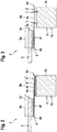
Figure 2 shows a schematic view of a cross section along the cut line II-II of the vehicle ofFigure 1 , -
Figure 3 shows a schematic view of a cross section along the cut line III-III of the vehicle ofFigure 1 , -
Figure 4 shows a schematic view of a cross section along the cut line IV-IV of the vehicle ofFigure 1 , -
Figure 5 shows the schematic view ofFigure 4 in an exemplary impact situation, -
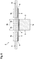
Figure 6 shows the schematic view ofFigure 2 according to a variant of the present invention, and -
Figure 7 shows a schematic view of the windshield assembly ofFigure 1 . -
Figure 1 shows anexemplary vehicle frame 1a of a vehicle 1 with awindshield assembly 2 according to the present invention. Thevehicle frame 1a preferably, but not necessarily, comprises a composite material, preferentially a fiber reinforced polymer material, such as carbon fiber reinforced polymer and/or glass fiber reinforced polymer. - By way of example, the
vehicle frame 1a is embodied as an airframe of a helicopter. However, only a segment of a fuselage of a helicopter, which illustratively represents a cockpit frame of the helicopter, is shown. The helicopter is, nevertheless, not shown in greater detail for simplicity and clarity of the drawings. - It should be noted that the present invention is not limited to mounting of the
inventive windshield assembly 2 to the cockpit frame of a helicopter. Instead, theinventive windshield assembly 2 can be mounted to multiple different frame structures, such as e. g. frame structures of aircrafts in general, frame structures of cars, frame structures of vessels, and so on. - Illustratively, the
windshield assembly 2 comprises at least onewindshield 3. In the following, reference is made to a single windshield, for simplicity and ease of the description. However, it is clear that thevehicle frame 1a may be provided with multiple different windshields and windshield assemblies, so that configurations with more than one windshield are likewise contemplated. - The
windshield 3 is preferably embodied by means of a transparent, light-permeable material. Advantageously, thewindshield 3 comprises a thermoplastic material. By way of example, thewindshield 3 comprises polycarbonate. - Preferably, the
windshield 3 has a curvature in at least one direction. Preferentially the curvature is provided such that thewindshield 3 exhibits an aerodynamic shape. - Furthermore, the
windshield 3 illustratively comprises anouter circumference 3c. Thisouter circumference 3c is defined by an outer contour of thewindshield 3 and is e. g. in the case of a rectangular base geometry of thewindshield 3 schematically defined by an underlying windshield length and height (3a and 3b inFigure 7 ). - The
windshield assembly 2 preferably further comprises at least oneflexible element 4 that is attached to thewindshield 3. In the following, reference is made to a single flexible element, for simplicity and ease of the description. However, it is clear that thewindshield assembly 2 may also be provided with more than one flexible element, so that configurations with two or more flexible elements are likewise contemplated. - According to one aspect, the
flexible element 4 connects thewindshield 3 to thevehicle frame 1a. Theflexible element 4 preferably absorbs loads resulting from an impact on thewindshield 3, in particular resulting from a foreign object impact, such as e. g. a bird strike. - Preferably, the
windshield assembly 2 is mounted to thevehicle frame 1a and closes an associatedopening 5 provided in thevehicle frame 1a. Theopening 5 is illustratively provided with an openinginner circumference 5c. This openinginner circumference 5c is defined by the inner contour of theopening 5 and is e. g. in the case of a rectangular base geometry of theopening 5 defined by an underlying opening length and height (5a and 5b inFigure 7 ). - According to one aspect, the
outer circumference 3c of thewindshield 3 is smaller than or equal to theinner circumference 5c of theopening 5 of thevehicle frame 1a. In other words, thewindshield 3 is preferably arranged on the vehicle 1 without overlapping thevehicle frame 1a. - However, it should be noted that the
windshield 3 may alternatively overlap thevehicle frame 1a. Nevertheless, in this case thewindshield 3 is preferably neither directly nor indirectly attached to thevehicle frame 1a and/or theflexible element 4 in a respective overlap region (8c inFigure 6 ), as described in more detail below with reference toFigure 6 . - The
flexible element 4 is preferably embodied as a plate-type element 4a that may at least be flexed. By way of example, theflexible element 4 may be realized by using a fiber reinforced polymer, such as a carbon fiber reinforced polymer, a glass fiber reinforced polymer and/or an aramid fiber reinforced polymer, and/or by using a metal, such as aluminum. - More specifically, the
flexible element 4 is preferably at least plastically deformable. Preferentially, theflexible element 4 is at least within predetermined tolerances non-destructively plastically deformable. Furthermore, or alternatively, theflexible element 4 may be elastically deformable within a predetermined range or degree of flexure. - In operation of the vehicle 1 and, more particularly, upon occurrence of an impact, e. g a foreign object impact such as a bird strike on the
windshield 3, thewindshield 3 pivots according to one aspect by means of theflexible element 4 relative to thevehicle frame 1a. In other words, theflexible element 4 functions as a hinge element upon occurrence of an impact. This functionality is described in more detail below with reference toFigure 5 . -
Figure 2 shows thevehicle frame 1a ofFigure 1 and thewindshield assembly 2 ofFigure 1 with thewindshield 3 and theflexible element 4. Theflexible element 4 is embodied as the plate-type element 4a ofFigure 1 and connects thewindshield 3 to thevehicle frame 1a. - According to one aspect, the
windshield 3 is bonded to afirst surface 4e of the plate-type element 4a by means of at least oneadhesive layer 6. Theadhesive layer 6 is preferably at least partially realized by a soft glue, such as e. g. a PU glue. - Illustratively, the
windshield 3 is bonded to theflexible element 4 in an area having alength 8a. This area, thus, defines an overlap area in which thewindshield 3 and theflexible element 4 overlap. The overlap area is hereinafter referred to as the "overlap area 8a". - The
flexible element 4, in turn, is according to one aspect bonded to thevehicle frame 1a by means of at least one other adhesive layer, which is also referred to with thereference sign 6, for simplicity and clarity. The otheradhesive layer 6 is preferably also at least partially realized by a soft glue, such as e. g. a PU glue. - Illustratively, the
flexible element 4 is bonded to thevehicle frame 1a in an area having alength 8b, which exemplarily corresponds to a width of thevehicle frame 1a. This area, thus, defines an overlap area in which theflexible element 4 and thevehicle frame 1a overlap. This overlap area is hereinafter referred to as the "overlap area 8b". - Between the
overlap areas flexible element 4 is preferably provided, i. e. a space that is neither bonded to thewindshield 3 nor to thevehicle frame 1a. This free space of theflexible element 4 is preferably the portion that defines the hinge element as described above and that remains free to allow movement in every direction in order to allow absorption of loads resulting from an impact. - According to one aspect, the
vehicle frame 1a and thewindshield 3 are arranged onopposite surfaces flexible element 4. By way of example, thesurface 4f of the plate-type element 4a that implements theflexible element 4 is bonded to thevehicle frame 1a and theopposed surface 4e of the plate-type element 4a that implements theflexible element 4 is bonded to thewindshield 3. - Illustratively, the plate-
type element 4a that implements theflexible element 4 is formed as a plate and comprises aninner opening 4b and has anouter circumference 4d such that theflexible element 4 has a picture frame-like shape. Furthermore, thevehicle frame 1a preferably comprises an associatedopening 5 with an openinginner circumference 5c. Moreover, thewindshield 3 has a windshieldouter circumference 3c. - According to one aspect, the windshield
outer circumference 3c is smaller than or equal to the openinginner circumference 5c and thewindshield 3 is preferably arranged by means of the plate-type element 4a on thevehicle frame 1a without overlapping thevehicle frame 1a. Thereby, thewindshield 3 preferably hermetically closes theinner opening 4b of the plate-type element 4a. -
Figure 3 shows thevehicle frame 1a ofFigure 2 and thewindshield assembly 2 ofFigure 2 with thewindshield 3 and theflexible element 4. As described above with reference toFigure 2 , thewindshield 3 is preferably bonded to thesurface 4e of the plate-type element 4a that implements theflexible element 4 by means of theadhesive layer 6. - However, in contrast to
Figure 2 theflexible element 4 is now attached to thevehicle frame 1a by means of at least one associatedfastener 7, such as e. g. a screw, rivet or bolt. In other words, the at least one associatedfastener 7 is used instead of the otheradhesive layer 6 that attaches theflexible element 4 to thevehicle frame 1a according toFigure 2 . -
Figure 4 shows thevehicle frame 1a ofFigure 2 and thewindshield assembly 2 ofFigure 2 with thewindshield 3 and theflexible element 4. As described above with reference toFigure 2 , thewindshield 3 is preferably bonded to thesurface 4e of the plate-type element 4a that implements theflexible element 4 by means of theadhesive layer 6, and thesurface 4f of the plate-type element 4a that implements theflexible element 4 is preferably bonded to thevehicle frame 1a by means of the otheradhesive layer 6. - However, in contrast to
Figure 2 theflexible element 4 is now further attached to thevehicle frame 1a by means of the at least one associatedfastener 7 ofFigure 3 , such as e. g. a screw, rivet or bolt. In other words, the at least one associatedfastener 7 is used in addition to the otheradhesive layer 6 that attaches theflexible element 4 to thevehicle frame 1a. -
Figure 5 shows thevehicle frame 1a ofFigure 2 and thewindshield assembly 2 ofFigure 2 with thewindshield 3 and theflexible element 4 upon occurrence of an impact on thewindshield 3. For instance, the impact may result from a foreign object impact, such as e. g. a bird strike or a drone strike. An arrow F represents a respective impact force associated with the impact. - Upon occurrence of the impact, the
flexible element 4 preferably experiences a deformation that preferentially allows to absorb a respective impact energy at least partly. Illustratively, theflexible element 4 acts as a hinge such that thewindshield 3 pivots at least sectionally around thevehicle frame 1a with arespective angle 9. As a respective pivotal movement preferably results from a deformation of theflexible element 4, theangle 9 is also referred to as the "deformation angle 9" and it indicates an inclination of thewindshield 3 relative to thevehicle frame 1a by means of the pivotal movement. - Illustratively, the pivotal movement resp. the deformation occurs in the free space located between the
overlap areas flexible element 4, embodied as a hinge element, which preferentially performs plastically. - It is preferred that the plastic deformation is non-destructive. However, dependent on the impact force F some damage, such as e. g. deterioration such as occurrence of a waviness of the
flexible element 4, may occur. Alternatively, the deformation may also at least partly be elastically, dependent on the material that is selected for implementation of theflexible element 4 and e. g. in comparatively small impact scenarios. - However, any damage to the
vehicle frame 1a itself or to the attachment of thevehicle frame 1a to theflexible element 4 and of the latter to thewindshield 3 should preferably be avoided, at least in a wide range of impact cases. In other words, it is acceptable if e. g. small ruptures of theflexible element 4 occur in comparatively heavy impact scenarios. -
Figure 6 shows thevehicle frame 1a ofFigure 2 and thewindshield assembly 2 ofFigure 2 with thewindshield 3 and theflexible element 4. As described above with reference toFigure 2 , thewindshield 3 is preferably bonded to theflexible element 4 by means of theadhesive layer 6, and theflexible element 4 is preferably bonded to thevehicle frame 1a by means of the otheradhesive layer 6. - However, in contrast to
Figure 2 theflexible element 4 is now illustratively extended beyond thevehicle frame 1a and also attached to anotherwindshield 10. According to one aspect, theother windshield 10 is bonded to theflexible element 4 by means of still another adhesive layer which is also referred to with thereference sign 6, for simplicity and clarity. This still anotheradhesive layer 6 is preferably also at least partially realized by a soft glue, such as e. g. a PU glue. - Similar to the
windshield 3, as explained above with reference toFigure 2 , thewindshield 10 is bonded to theflexible element 4 in an area having thelength 8a. This area, thus, defines an overlap area in which thewindshield 10 and theflexible element 4 overlap. This overlap area is hereinafter also referred to as the "overlap area 8a". - In contrast to
Figure 2 , however, thewindshield 3 now overlaps thevehicle frame 1a in an area having alength 8c. This area, thus, defines an overlap area in which thewindshield 3 and thevehicle frame 1a overlap. This overlap area is hereinafter referred to as the "overlap area 8c". This applies likewise to thewindshield 10, which also illustratively overlaps thevehicle frame 1a in arespective overlap area 8c. - According to one aspect, the
windshields respective overlap areas 8c neither attached to theflexible element 4, nor to thevehicle frame 1a. Thus, the pivotal movement of thewindshield 3 as described above with reference toFigure 5 , and likewise of thewindshield 10, is not affected by theoverlap areas 8c. -
Figure 7 shows thevehicle frame 1a ofFigure 1 and thewindshield assembly 2 ofFigure 2 to Figure 5 with thewindshield 3 and theflexible element 4. For describing an illustrative mounting of thewindshield assembly 2 to thevehicle frame 1a, all elements are exemplarily illustrated with a flat rectangular base structure, for simplicity and clarity of the drawing and the description. - As described above, the
flexible element 4, which is exemplarily embodied as the plate-type element 4a, is attached to thevehicle frame 1a. Between the plate-type element 4a and thevehicle frame 1a theoverlap area 8b is formed. The length resp.width 8b of theoverlap area 8b is defined by theouter circumference 4d of the plate-type element 4a and the openinginner circumference 5c of thevehicle frame 1a. The openinginner circumference 5c is illustratively defined by arespective opening length 5a and openingheight 5b. - Furthermore, as also described above, the
flexible element 4 is attached to thewindshield 3. Between thewindshield 3 and theflexible element 4 theoverlap area 8a is formed. The length resp.width 8a of theoverlap area 8a is defined by the windshieldouter circumference 3c and theinner opening circumference 4c of the plate-type element 4a. The windshieldouter circumference 3c is illustratively defined by arespective windshield length 3a andwindshield height 3b. - Preferably, the
inner opening circumference 4c is smaller than the windshield'souter circumference 3c. Furthermore, the flexible element'souter circumference 4d is preferentially greater than the openinginner circumference 5c of the associatedopening 5 of thevehicle frame 1a. - Finally, it should be noted that modifications to the above-described exemplary implementations of the present invention are also within the common knowledge of the person skilled in the art and, thus, also considered as being part of the present invention.
- For instance, the
flexible element 4 is described above as a plate-type element which is according to one aspect embodied in the form of a picture frame-like component. However, the present invention is not restricted to such an implementation and a given windshield assembly may also be provided with several independent strip-like flexible elements, which may still be embodied as plate-type elements, resp. as flat and comparatively thin elements. - Furthermore, the flexible element must not necessarily be energy absorbing as such. In fact, it may be sufficient that the flexible element simply transfers occurring impact energy from the windshield to the vehicle frame.
-
- 1
- vehicle
- 1a
- vehicle frame
- 2
- windshield assembly
- 3
- windshield
- 3a
- windshield length
- 3b
- windshield height
- 3c
- windshield outer circumference
- 4
- flexible element
- 4a
- plate-type element
- 4b
- plate-type element inner opening
- 4c
- inner opening circumference
- 4d
- plate-type element outer circumference
- 4e
- windshield-side surface of plate-type element
- 4f
- vehicle frame-side surface of plate-type element
- 5
- opening
- 5a
- opening length
- 5b
- opening height
- 5c
- opening inner circumference
- 6
- adhesive layer
- 7
- fastener
- 8a
- overlap between the windshield and the flexible element
- 8b
- overlap between the flexible element and the vehicle frame
- 8c
- overlap between the windshield and the vehicle frame
- 9
- deformation angle
- 10
- windshield
- F
- Force
Claims (15)
- A vehicle (1) with a vehicle frame (1a) and a windshield assembly (2) that is mounted to the vehicle frame (1a) and closes an associated opening (5) provided in the vehicle frame (1a), wherein the windshield assembly (2) comprises at least one flexible element (4) and at least one windshield (3), the at least one flexible element (4) being attached to the at least one windshield (3) and connecting the at least one windshield (3) to the vehicle frame (1a) for at least partially absorbing loads resulting from an impact on the at least one windshield (4), in particular resulting from a foreign object impact,
characterized in that
the at least one flexible element (4) connects the at least one windshield (3) to the vehicle frame (1a) such that the at least one windshield (3) pivots relative to the vehicle frame (1a) by means of the at least one flexible element (4) upon occurrence of an impact on the at least one windshield (3) such that the at least one flexible element (4) defines a hinge element. - The vehicle (1) of claim 1,
characterized in that the at least one windshield (3) is provided with an outer circumference (3c) that is smaller than or equal to an inner circumference (5c) of the associated opening (5) of the vehicle frame (1a) such that the at least one windshield (3) is arranged on the vehicle (1) without overlapping the vehicle frame (1a). - The vehicle (1) of claim 1,
characterized in that the at least one windshield (3) overlaps the vehicle frame (1a) in a respective overlap region (8c) without being attached to the at least one flexible element (4) and/or the vehicle frame (1a) in the respective overlap region (8c). - The vehicle (1) of any one of the preceding claims,
characterized in that the at least one flexible element (4) is a plate-type element (4a) with an inner opening (4b). - The vehicle (1) of claim 4,
characterized in that the inner opening (4b) has a circumference (4c) that is smaller than an outer circumference (3c) of the at least one windshield (3), wherein the at least one flexible element (4) has an outer circumference (4d) that is greater than an inner circumference (5c) of the associated opening (5) of the vehicle frame (1a). - The vehicle (1) of any one of the preceding claims,
characterized in that the at least one flexible element (4) comprises a fiber reinforced polymer and/or metal. - The vehicle (1) of any one of the preceding claims,
characterized in that the at least one flexible element (4) is bonded to the vehicle frame (1a) by means of at least one adhesive layer (6). - The vehicle (1) of any one of the preceding claims,
characterized in that the at least one flexible element (4) is attached to the vehicle frame (1a) by means of at least one fastener (7). - The vehicle (1) of any one of the preceding claims, characterized in that the at least one windshield (3) is bonded to the at least one flexible element (4) by means of at least one adhesive layer (6).
- The vehicle (1) of any one of the preceding claims,
characterized in that the at least one windshield (3) comprises thermoplastic material. - The vehicle (1) of any one of the preceding claims,
characterized in that the at least one windshield (3) comprises polycarbonate. - The vehicle (1) of any one of the preceding claims,
characterized in that the at least one windshield (3) has a curvature in at least one direction. - The vehicle (1) of any one of the preceding claims,
characterized in that the vehicle frame (1a) comprises composite material, in particular fiber reinforced polymer material. - The vehicle (1) of any one of the preceding claims,
characterized in that the at least one windshield (3) and the vehicle frame (1a) are arranged on opposite surfaces (4e, 4f) of the at least one flexible element (4). - The vehicle (1) of any one of the preceding claims, characterized in that the vehicle (1) is embodied as a helicopter.
Priority Applications (3)
| Application Number | Priority Date | Filing Date | Title |
|---|---|---|---|
| EP18400036.2A EP3666641B1 (en) | 2018-12-11 | 2018-12-11 | Foreign object impact proof windshield assembly |
| US16/594,343 US11827332B2 (en) | 2018-12-11 | 2019-10-07 | Foreign object impact proof windshield assembly |
| CA3062300A CA3062300C (en) | 2018-12-11 | 2019-11-20 | Foreign object impact proof windshield assembly |
Applications Claiming Priority (1)
| Application Number | Priority Date | Filing Date | Title |
|---|---|---|---|
| EP18400036.2A EP3666641B1 (en) | 2018-12-11 | 2018-12-11 | Foreign object impact proof windshield assembly |
Publications (2)
| Publication Number | Publication Date |
|---|---|
| EP3666641A1 true EP3666641A1 (en) | 2020-06-17 |
| EP3666641B1 EP3666641B1 (en) | 2021-05-05 |
Family
ID=65243290
Family Applications (1)
| Application Number | Title | Priority Date | Filing Date |
|---|---|---|---|
| EP18400036.2A Active EP3666641B1 (en) | 2018-12-11 | 2018-12-11 | Foreign object impact proof windshield assembly |
Country Status (3)
| Country | Link |
|---|---|
| US (1) | US11827332B2 (en) |
| EP (1) | EP3666641B1 (en) |
| CA (1) | CA3062300C (en) |
Families Citing this family (2)
| Publication number | Priority date | Publication date | Assignee | Title |
|---|---|---|---|---|
| US12358605B2 (en) * | 2022-03-09 | 2025-07-15 | The Boeing Company | Vehicle window assembly |
| FR3163637A1 (en) | 2024-06-24 | 2025-12-26 | Airbus Helicopters | Aircraft equipped with a transparent wall attached to a structure by a shock-absorbing system |
Citations (10)
| Publication number | Priority date | Publication date | Assignee | Title |
|---|---|---|---|---|
| US2784926A (en) * | 1953-03-30 | 1957-03-12 | Lockheed Aircraft Corp | Protected aircraft enclosures |
| DE19921871A1 (en) | 1998-05-12 | 1999-11-18 | Honda Motor Co Ltd | Front windscreen support structure for a vehicle |
| EP1518780A1 (en) | 2003-09-29 | 2005-03-30 | Mazda Motor Corporation | Vehicle front-body structure |
| JP2008100533A (en) | 2006-10-17 | 2008-05-01 | Toyota Auto Body Co Ltd | Car cowl top structure |
| DE102011081784A1 (en) | 2010-09-07 | 2012-03-08 | Ford Global Technologies, Llc | Energy absorbing cowl structure |
| WO2014183614A1 (en) * | 2013-05-16 | 2014-11-20 | 一禾科技发展(上海)有限公司 | Armed helicopter transparent component fastening structure and fastening method for blast-defense and impact-attenuation |
| EP2907744A1 (en) * | 2014-02-18 | 2015-08-19 | AIRBUS HELICOPTERS DEUTSCHLAND GmbH | Windshield mounting assembly |
| WO2015152096A1 (en) | 2014-04-03 | 2015-10-08 | トヨタ自動車株式会社 | Cowl structure for vehicle |
| EP3056412A1 (en) | 2015-02-16 | 2016-08-17 | Toyota Jidosha Kabushiki Kaisha | Vehicle cowl portion structure |
| EP3100947A1 (en) * | 2015-06-05 | 2016-12-07 | AIRBUS HELICOPTERS DEUTSCHLAND GmbH | A jettisonable emergency exit for a vehicle |
Family Cites Families (10)
| Publication number | Priority date | Publication date | Assignee | Title |
|---|---|---|---|---|
| US2398886A (en) * | 1942-05-15 | 1946-04-23 | Libbey Owens Ford Glass Co | Laminated glass structure |
| US2392129A (en) * | 1943-04-23 | 1946-01-01 | Pittsburgh Plate Glass Co | Laminated glass closure unit |
| US2403060A (en) * | 1943-04-23 | 1946-07-02 | Pittsburgh Plate Glass Co | Installation for laminated glass |
| US2679467A (en) * | 1951-07-21 | 1954-05-25 | Pittsburgh Plate Glass Co | Pressure blowout safety closure |
| US4204374A (en) * | 1977-11-10 | 1980-05-27 | The Sierracin Corporation | Edge design for impact resistant windshield |
| US4650240A (en) * | 1985-02-04 | 1987-03-17 | Rinella Richard J | Windshield mounting assembly |
| JP2004009965A (en) * | 2002-06-10 | 2004-01-15 | Honda Motor Co Ltd | Vehicle windshield mounting structure |
| FR3004161B1 (en) * | 2013-04-04 | 2017-12-08 | Astrium Sas | GLAZING FOR SPACE AIRCRAFT |
| US10538305B2 (en) * | 2017-01-19 | 2020-01-21 | Tyson Valdez, LLC | Dovetail aircraft windscreen |
| US10577075B1 (en) * | 2017-05-03 | 2020-03-03 | Northrop Grumman Systems Corporation | Interlocking device for aircraft cockpit frames |
-
2018
- 2018-12-11 EP EP18400036.2A patent/EP3666641B1/en active Active
-
2019
- 2019-10-07 US US16/594,343 patent/US11827332B2/en active Active
- 2019-11-20 CA CA3062300A patent/CA3062300C/en active Active
Patent Citations (12)
| Publication number | Priority date | Publication date | Assignee | Title |
|---|---|---|---|---|
| US2784926A (en) * | 1953-03-30 | 1957-03-12 | Lockheed Aircraft Corp | Protected aircraft enclosures |
| DE19921871A1 (en) | 1998-05-12 | 1999-11-18 | Honda Motor Co Ltd | Front windscreen support structure for a vehicle |
| US6193304B1 (en) | 1998-05-12 | 2001-02-27 | Honda Giken Kogyo Kabushiki Kaisha | Windshield supporting structure |
| EP1518780A1 (en) | 2003-09-29 | 2005-03-30 | Mazda Motor Corporation | Vehicle front-body structure |
| JP2008100533A (en) | 2006-10-17 | 2008-05-01 | Toyota Auto Body Co Ltd | Car cowl top structure |
| DE102011081784A1 (en) | 2010-09-07 | 2012-03-08 | Ford Global Technologies, Llc | Energy absorbing cowl structure |
| WO2014183614A1 (en) * | 2013-05-16 | 2014-11-20 | 一禾科技发展(上海)有限公司 | Armed helicopter transparent component fastening structure and fastening method for blast-defense and impact-attenuation |
| EP2907744A1 (en) * | 2014-02-18 | 2015-08-19 | AIRBUS HELICOPTERS DEUTSCHLAND GmbH | Windshield mounting assembly |
| US20150232169A1 (en) | 2014-02-18 | 2015-08-20 | Airbus Helicopters Deutschland GmbH | Windshield mounting assembly |
| WO2015152096A1 (en) | 2014-04-03 | 2015-10-08 | トヨタ自動車株式会社 | Cowl structure for vehicle |
| EP3056412A1 (en) | 2015-02-16 | 2016-08-17 | Toyota Jidosha Kabushiki Kaisha | Vehicle cowl portion structure |
| EP3100947A1 (en) * | 2015-06-05 | 2016-12-07 | AIRBUS HELICOPTERS DEUTSCHLAND GmbH | A jettisonable emergency exit for a vehicle |
Also Published As
| Publication number | Publication date |
|---|---|
| CA3062300C (en) | 2021-10-19 |
| EP3666641B1 (en) | 2021-05-05 |
| US20200180748A1 (en) | 2020-06-11 |
| US11827332B2 (en) | 2023-11-28 |
| CA3062300A1 (en) | 2020-02-27 |
Similar Documents
| Publication | Publication Date | Title |
|---|---|---|
| EP2117922B1 (en) | Compliant panel for aircraft | |
| US8434716B2 (en) | Compliant crown panel for an aircraft | |
| US10611456B2 (en) | Aircraft with a drag neutral vehicle window | |
| EP1744950B1 (en) | Load bearing window | |
| JP6927284B2 (en) | Laminated glass for vehicles with inner mirror | |
| EP2426365A1 (en) | Fastening structure of resin member | |
| US20090127392A1 (en) | Protection device | |
| JP6312324B2 (en) | Windshield glass assembly | |
| CA3062300C (en) | Foreign object impact proof windshield assembly | |
| CN101439682B (en) | Vehicle seat frame with a hinge mounting | |
| US20250388313A1 (en) | Aircraft with a transparent wall fixed to a structure via a shock protection system | |
| US12358605B2 (en) | Vehicle window assembly | |
| WO2026050006A1 (en) | Glass article with adhesive layer configured for delamination of glass substrate in response to headform impact |
Legal Events
| Date | Code | Title | Description |
|---|---|---|---|
| PUAI | Public reference made under article 153(3) epc to a published international application that has entered the european phase |
Free format text: ORIGINAL CODE: 0009012 |
|
| STAA | Information on the status of an ep patent application or granted ep patent |
Free format text: STATUS: THE APPLICATION HAS BEEN PUBLISHED |
|
| STAA | Information on the status of an ep patent application or granted ep patent |
Free format text: STATUS: REQUEST FOR EXAMINATION WAS MADE |
|
| AK | Designated contracting states |
Kind code of ref document: A1 Designated state(s): AL AT BE BG CH CY CZ DE DK EE ES FI FR GB GR HR HU IE IS IT LI LT LU LV MC MK MT NL NO PL PT RO RS SE SI SK SM TR |
|
| AX | Request for extension of the european patent |
Extension state: BA ME |
|
| 17P | Request for examination filed |
Effective date: 20200528 |
|
| RBV | Designated contracting states (corrected) |
Designated state(s): AL AT BE BG CH CY CZ DE DK EE ES FI FR GB GR HR HU IE IS IT LI LT LU LV MC MK MT NL NO PL PT RO RS SE SI SK SM TR |
|
| GRAP | Despatch of communication of intention to grant a patent |
Free format text: ORIGINAL CODE: EPIDOSNIGR1 |
|
| STAA | Information on the status of an ep patent application or granted ep patent |
Free format text: STATUS: GRANT OF PATENT IS INTENDED |
|
| RIC1 | Information provided on ipc code assigned before grant |
Ipc: B60J 1/00 20060101ALI20210119BHEP Ipc: B60J 1/02 20060101ALN20210119BHEP Ipc: B60R 21/34 20110101ALN20210119BHEP Ipc: B64C 1/14 20060101AFI20210119BHEP |
|
| INTG | Intention to grant announced |
Effective date: 20210217 |
|
| GRAS | Grant fee paid |
Free format text: ORIGINAL CODE: EPIDOSNIGR3 |
|
| GRAA | (expected) grant |
Free format text: ORIGINAL CODE: 0009210 |
|
| STAA | Information on the status of an ep patent application or granted ep patent |
Free format text: STATUS: THE PATENT HAS BEEN GRANTED |
|
| RIN1 | Information on inventor provided before grant (corrected) |
Inventor name: REICHENSPERGER, CHRISTIAN Inventor name: SCHNIZER, MIKKO Inventor name: WOLTERS, LARS |
|
| AK | Designated contracting states |
Kind code of ref document: B1 Designated state(s): AL AT BE BG CH CY CZ DE DK EE ES FI FR GB GR HR HU IE IS IT LI LT LU LV MC MK MT NL NO PL PT RO RS SE SI SK SM TR |
|
| REG | Reference to a national code |
Ref country code: GB Ref legal event code: FG4D |
|
| REG | Reference to a national code |
Ref country code: CH Ref legal event code: EP |
|
| REG | Reference to a national code |
Ref country code: AT Ref legal event code: REF Ref document number: 1389505 Country of ref document: AT Kind code of ref document: T Effective date: 20210515 |
|
| REG | Reference to a national code |
Ref country code: IE Ref legal event code: FG4D |
|
| REG | Reference to a national code |
Ref country code: DE Ref legal event code: R096 Ref document number: 602018016600 Country of ref document: DE |
|
| REG | Reference to a national code |
Ref country code: LT Ref legal event code: MG9D |
|
| REG | Reference to a national code |
Ref country code: AT Ref legal event code: MK05 Ref document number: 1389505 Country of ref document: AT Kind code of ref document: T Effective date: 20210505 |
|
| PG25 | Lapsed in a contracting state [announced via postgrant information from national office to epo] |
Ref country code: HR Free format text: LAPSE BECAUSE OF FAILURE TO SUBMIT A TRANSLATION OF THE DESCRIPTION OR TO PAY THE FEE WITHIN THE PRESCRIBED TIME-LIMIT Effective date: 20210505 Ref country code: LT Free format text: LAPSE BECAUSE OF FAILURE TO SUBMIT A TRANSLATION OF THE DESCRIPTION OR TO PAY THE FEE WITHIN THE PRESCRIBED TIME-LIMIT Effective date: 20210505 Ref country code: FI Free format text: LAPSE BECAUSE OF FAILURE TO SUBMIT A TRANSLATION OF THE DESCRIPTION OR TO PAY THE FEE WITHIN THE PRESCRIBED TIME-LIMIT Effective date: 20210505 Ref country code: AT Free format text: LAPSE BECAUSE OF FAILURE TO SUBMIT A TRANSLATION OF THE DESCRIPTION OR TO PAY THE FEE WITHIN THE PRESCRIBED TIME-LIMIT Effective date: 20210505 Ref country code: BG Free format text: LAPSE BECAUSE OF FAILURE TO SUBMIT A TRANSLATION OF THE DESCRIPTION OR TO PAY THE FEE WITHIN THE PRESCRIBED TIME-LIMIT Effective date: 20210805 |
|
| PG25 | Lapsed in a contracting state [announced via postgrant information from national office to epo] |
Ref country code: IS Free format text: LAPSE BECAUSE OF FAILURE TO SUBMIT A TRANSLATION OF THE DESCRIPTION OR TO PAY THE FEE WITHIN THE PRESCRIBED TIME-LIMIT Effective date: 20210905 Ref country code: GR Free format text: LAPSE BECAUSE OF FAILURE TO SUBMIT A TRANSLATION OF THE DESCRIPTION OR TO PAY THE FEE WITHIN THE PRESCRIBED TIME-LIMIT Effective date: 20210806 Ref country code: NO Free format text: LAPSE BECAUSE OF FAILURE TO SUBMIT A TRANSLATION OF THE DESCRIPTION OR TO PAY THE FEE WITHIN THE PRESCRIBED TIME-LIMIT Effective date: 20210805 Ref country code: PT Free format text: LAPSE BECAUSE OF FAILURE TO SUBMIT A TRANSLATION OF THE DESCRIPTION OR TO PAY THE FEE WITHIN THE PRESCRIBED TIME-LIMIT Effective date: 20210906 Ref country code: LV Free format text: LAPSE BECAUSE OF FAILURE TO SUBMIT A TRANSLATION OF THE DESCRIPTION OR TO PAY THE FEE WITHIN THE PRESCRIBED TIME-LIMIT Effective date: 20210505 Ref country code: PL Free format text: LAPSE BECAUSE OF FAILURE TO SUBMIT A TRANSLATION OF THE DESCRIPTION OR TO PAY THE FEE WITHIN THE PRESCRIBED TIME-LIMIT Effective date: 20210505 Ref country code: RS Free format text: LAPSE BECAUSE OF FAILURE TO SUBMIT A TRANSLATION OF THE DESCRIPTION OR TO PAY THE FEE WITHIN THE PRESCRIBED TIME-LIMIT Effective date: 20210505 Ref country code: SE Free format text: LAPSE BECAUSE OF FAILURE TO SUBMIT A TRANSLATION OF THE DESCRIPTION OR TO PAY THE FEE WITHIN THE PRESCRIBED TIME-LIMIT Effective date: 20210505 |
|
| REG | Reference to a national code |
Ref country code: NL Ref legal event code: MP Effective date: 20210505 |
|
| PG25 | Lapsed in a contracting state [announced via postgrant information from national office to epo] |
Ref country code: NL Free format text: LAPSE BECAUSE OF FAILURE TO SUBMIT A TRANSLATION OF THE DESCRIPTION OR TO PAY THE FEE WITHIN THE PRESCRIBED TIME-LIMIT Effective date: 20210505 |
|
| PG25 | Lapsed in a contracting state [announced via postgrant information from national office to epo] |
Ref country code: SM Free format text: LAPSE BECAUSE OF FAILURE TO SUBMIT A TRANSLATION OF THE DESCRIPTION OR TO PAY THE FEE WITHIN THE PRESCRIBED TIME-LIMIT Effective date: 20210505 Ref country code: SK Free format text: LAPSE BECAUSE OF FAILURE TO SUBMIT A TRANSLATION OF THE DESCRIPTION OR TO PAY THE FEE WITHIN THE PRESCRIBED TIME-LIMIT Effective date: 20210505 Ref country code: EE Free format text: LAPSE BECAUSE OF FAILURE TO SUBMIT A TRANSLATION OF THE DESCRIPTION OR TO PAY THE FEE WITHIN THE PRESCRIBED TIME-LIMIT Effective date: 20210505 Ref country code: ES Free format text: LAPSE BECAUSE OF FAILURE TO SUBMIT A TRANSLATION OF THE DESCRIPTION OR TO PAY THE FEE WITHIN THE PRESCRIBED TIME-LIMIT Effective date: 20210505 Ref country code: DK Free format text: LAPSE BECAUSE OF FAILURE TO SUBMIT A TRANSLATION OF THE DESCRIPTION OR TO PAY THE FEE WITHIN THE PRESCRIBED TIME-LIMIT Effective date: 20210505 Ref country code: CZ Free format text: LAPSE BECAUSE OF FAILURE TO SUBMIT A TRANSLATION OF THE DESCRIPTION OR TO PAY THE FEE WITHIN THE PRESCRIBED TIME-LIMIT Effective date: 20210505 Ref country code: RO Free format text: LAPSE BECAUSE OF FAILURE TO SUBMIT A TRANSLATION OF THE DESCRIPTION OR TO PAY THE FEE WITHIN THE PRESCRIBED TIME-LIMIT Effective date: 20210505 |
|
| REG | Reference to a national code |
Ref country code: DE Ref legal event code: R097 Ref document number: 602018016600 Country of ref document: DE |
|
| PLBE | No opposition filed within time limit |
Free format text: ORIGINAL CODE: 0009261 |
|
| STAA | Information on the status of an ep patent application or granted ep patent |
Free format text: STATUS: NO OPPOSITION FILED WITHIN TIME LIMIT |
|
| 26N | No opposition filed |
Effective date: 20220208 |
|
| PG25 | Lapsed in a contracting state [announced via postgrant information from national office to epo] |
Ref country code: IS Free format text: LAPSE BECAUSE OF FAILURE TO SUBMIT A TRANSLATION OF THE DESCRIPTION OR TO PAY THE FEE WITHIN THE PRESCRIBED TIME-LIMIT Effective date: 20210905 Ref country code: AL Free format text: LAPSE BECAUSE OF FAILURE TO SUBMIT A TRANSLATION OF THE DESCRIPTION OR TO PAY THE FEE WITHIN THE PRESCRIBED TIME-LIMIT Effective date: 20210505 |
|
| PG25 | Lapsed in a contracting state [announced via postgrant information from national office to epo] |
Ref country code: MC Free format text: LAPSE BECAUSE OF FAILURE TO SUBMIT A TRANSLATION OF THE DESCRIPTION OR TO PAY THE FEE WITHIN THE PRESCRIBED TIME-LIMIT Effective date: 20210505 |
|
| REG | Reference to a national code |
Ref country code: CH Ref legal event code: PL |
|
| REG | Reference to a national code |
Ref country code: BE Ref legal event code: MM Effective date: 20211231 |
|
| PG25 | Lapsed in a contracting state [announced via postgrant information from national office to epo] |
Ref country code: LU Free format text: LAPSE BECAUSE OF NON-PAYMENT OF DUE FEES Effective date: 20211211 Ref country code: IE Free format text: LAPSE BECAUSE OF NON-PAYMENT OF DUE FEES Effective date: 20211211 |
|
| PG25 | Lapsed in a contracting state [announced via postgrant information from national office to epo] |
Ref country code: BE Free format text: LAPSE BECAUSE OF NON-PAYMENT OF DUE FEES Effective date: 20211231 |
|
| PG25 | Lapsed in a contracting state [announced via postgrant information from national office to epo] |
Ref country code: LI Free format text: LAPSE BECAUSE OF NON-PAYMENT OF DUE FEES Effective date: 20211231 Ref country code: CH Free format text: LAPSE BECAUSE OF NON-PAYMENT OF DUE FEES Effective date: 20211231 |
|
| PG25 | Lapsed in a contracting state [announced via postgrant information from national office to epo] |
Ref country code: CY Free format text: LAPSE BECAUSE OF FAILURE TO SUBMIT A TRANSLATION OF THE DESCRIPTION OR TO PAY THE FEE WITHIN THE PRESCRIBED TIME-LIMIT Effective date: 20210505 |
|
| P01 | Opt-out of the competence of the unified patent court (upc) registered |
Effective date: 20230530 |
|
| PG25 | Lapsed in a contracting state [announced via postgrant information from national office to epo] |
Ref country code: HU Free format text: LAPSE BECAUSE OF FAILURE TO SUBMIT A TRANSLATION OF THE DESCRIPTION OR TO PAY THE FEE WITHIN THE PRESCRIBED TIME-LIMIT; INVALID AB INITIO Effective date: 20181211 |
|
| PG25 | Lapsed in a contracting state [announced via postgrant information from national office to epo] |
Ref country code: MK Free format text: LAPSE BECAUSE OF FAILURE TO SUBMIT A TRANSLATION OF THE DESCRIPTION OR TO PAY THE FEE WITHIN THE PRESCRIBED TIME-LIMIT Effective date: 20210505 |
|
| PG25 | Lapsed in a contracting state [announced via postgrant information from national office to epo] |
Ref country code: MT Free format text: LAPSE BECAUSE OF FAILURE TO SUBMIT A TRANSLATION OF THE DESCRIPTION OR TO PAY THE FEE WITHIN THE PRESCRIBED TIME-LIMIT Effective date: 20210505 |
|
| PG25 | Lapsed in a contracting state [announced via postgrant information from national office to epo] |
Ref country code: TR Free format text: LAPSE BECAUSE OF FAILURE TO SUBMIT A TRANSLATION OF THE DESCRIPTION OR TO PAY THE FEE WITHIN THE PRESCRIBED TIME-LIMIT Effective date: 20210505 |
|
| PGFP | Annual fee paid to national office [announced via postgrant information from national office to epo] |
Ref country code: DE Payment date: 20251211 Year of fee payment: 8 |
|
| PGFP | Annual fee paid to national office [announced via postgrant information from national office to epo] |
Ref country code: GB Payment date: 20251219 Year of fee payment: 8 |
|
| PGFP | Annual fee paid to national office [announced via postgrant information from national office to epo] |
Ref country code: IT Payment date: 20251223 Year of fee payment: 8 |
|
| PGFP | Annual fee paid to national office [announced via postgrant information from national office to epo] |
Ref country code: FR Payment date: 20251229 Year of fee payment: 8 |