EP3666571B1 - TRANSMISSION DEVICE, ELECTRIC VEHICLE WITH THE DEVICE AND METHOD FOR CONTROLLING THE DEVICE - Google Patents
TRANSMISSION DEVICE, ELECTRIC VEHICLE WITH THE DEVICE AND METHOD FOR CONTROLLING THE DEVICE Download PDFInfo
- Publication number
- EP3666571B1 EP3666571B1 EP17922906.7A EP17922906A EP3666571B1 EP 3666571 B1 EP3666571 B1 EP 3666571B1 EP 17922906 A EP17922906 A EP 17922906A EP 3666571 B1 EP3666571 B1 EP 3666571B1
- Authority
- EP
- European Patent Office
- Prior art keywords
- gear
- power source
- rotating inner
- inner ring
- input shaft
- Prior art date
- Legal status (The legal status is an assumption and is not a legal conclusion. Google has not performed a legal analysis and makes no representation as to the accuracy of the status listed.)
- Active
Links
Images


Classifications
-
- F—MECHANICAL ENGINEERING; LIGHTING; HEATING; WEAPONS; BLASTING
- F16—ENGINEERING ELEMENTS AND UNITS; GENERAL MEASURES FOR PRODUCING AND MAINTAINING EFFECTIVE FUNCTIONING OF MACHINES OR INSTALLATIONS; THERMAL INSULATION IN GENERAL
- F16H—GEARING
- F16H3/00—Toothed gearings for conveying rotary motion with variable gear ratio or for reversing rotary motion
- F16H3/44—Toothed gearings for conveying rotary motion with variable gear ratio or for reversing rotary motion using gears having orbital motion
- F16H3/72—Toothed gearings for conveying rotary motion with variable gear ratio or for reversing rotary motion using gears having orbital motion with a secondary drive, e.g. regulating motor, in order to vary speed continuously
- F16H3/724—Toothed gearings for conveying rotary motion with variable gear ratio or for reversing rotary motion using gears having orbital motion with a secondary drive, e.g. regulating motor, in order to vary speed continuously using externally powered electric machines
-
- F—MECHANICAL ENGINEERING; LIGHTING; HEATING; WEAPONS; BLASTING
- F16—ENGINEERING ELEMENTS AND UNITS; GENERAL MEASURES FOR PRODUCING AND MAINTAINING EFFECTIVE FUNCTIONING OF MACHINES OR INSTALLATIONS; THERMAL INSULATION IN GENERAL
- F16H—GEARING
- F16H1/00—Toothed gearings for conveying rotary motion
- F16H1/28—Toothed gearings for conveying rotary motion with gears having orbital motion
- F16H1/32—Toothed gearings for conveying rotary motion with gears having orbital motion in which the central axis of the gearing lies inside the periphery of an orbital gear
-
- B—PERFORMING OPERATIONS; TRANSPORTING
- B60—VEHICLES IN GENERAL
- B60K—ARRANGEMENT OR MOUNTING OF PROPULSION UNITS OR OF TRANSMISSIONS IN VEHICLES; ARRANGEMENT OR MOUNTING OF PLURAL DIVERSE PRIME-MOVERS IN VEHICLES; AUXILIARY DRIVES FOR VEHICLES; INSTRUMENTATION OR DASHBOARDS FOR VEHICLES; ARRANGEMENTS IN CONNECTION WITH COOLING, AIR INTAKE, GAS EXHAUST OR FUEL SUPPLY OF PROPULSION UNITS IN VEHICLES
- B60K1/00—Arrangement or mounting of electrical propulsion units
- B60K1/02—Arrangement or mounting of electrical propulsion units comprising more than one electric motor
-
- B—PERFORMING OPERATIONS; TRANSPORTING
- B60—VEHICLES IN GENERAL
- B60K—ARRANGEMENT OR MOUNTING OF PROPULSION UNITS OR OF TRANSMISSIONS IN VEHICLES; ARRANGEMENT OR MOUNTING OF PLURAL DIVERSE PRIME-MOVERS IN VEHICLES; AUXILIARY DRIVES FOR VEHICLES; INSTRUMENTATION OR DASHBOARDS FOR VEHICLES; ARRANGEMENTS IN CONNECTION WITH COOLING, AIR INTAKE, GAS EXHAUST OR FUEL SUPPLY OF PROPULSION UNITS IN VEHICLES
- B60K17/00—Arrangement or mounting of transmissions in vehicles
- B60K17/04—Arrangement or mounting of transmissions in vehicles characterised by arrangement, location or kind of gearing
- B60K17/06—Arrangement or mounting of transmissions in vehicles characterised by arrangement, location or kind of gearing of change-speed gearing
- B60K17/08—Arrangement or mounting of transmissions in vehicles characterised by arrangement, location or kind of gearing of change-speed gearing of mechanical type
-
- B—PERFORMING OPERATIONS; TRANSPORTING
- B60—VEHICLES IN GENERAL
- B60K—ARRANGEMENT OR MOUNTING OF PROPULSION UNITS OR OF TRANSMISSIONS IN VEHICLES; ARRANGEMENT OR MOUNTING OF PLURAL DIVERSE PRIME-MOVERS IN VEHICLES; AUXILIARY DRIVES FOR VEHICLES; INSTRUMENTATION OR DASHBOARDS FOR VEHICLES; ARRANGEMENTS IN CONNECTION WITH COOLING, AIR INTAKE, GAS EXHAUST OR FUEL SUPPLY OF PROPULSION UNITS IN VEHICLES
- B60K17/00—Arrangement or mounting of transmissions in vehicles
- B60K17/04—Arrangement or mounting of transmissions in vehicles characterised by arrangement, location or kind of gearing
- B60K17/12—Arrangement or mounting of transmissions in vehicles characterised by arrangement, location or kind of gearing of electric gearing
-
- B—PERFORMING OPERATIONS; TRANSPORTING
- B60—VEHICLES IN GENERAL
- B60L—PROPULSION OF ELECTRICALLY-PROPELLED VEHICLES; SUPPLYING ELECTRIC POWER FOR AUXILIARY EQUIPMENT OF ELECTRICALLY-PROPELLED VEHICLES; ELECTRODYNAMIC BRAKE SYSTEMS FOR VEHICLES IN GENERAL; MAGNETIC SUSPENSION OR LEVITATION FOR VEHICLES; MONITORING OPERATING VARIABLES OF ELECTRICALLY-PROPELLED VEHICLES; ELECTRIC SAFETY DEVICES FOR ELECTRICALLY-PROPELLED VEHICLES
- B60L50/00—Electric propulsion with power supplied within the vehicle
- B60L50/50—Electric propulsion with power supplied within the vehicle using propulsion power supplied by batteries or fuel cells
- B60L50/60—Electric propulsion with power supplied within the vehicle using propulsion power supplied by batteries or fuel cells using power supplied by batteries
- B60L50/61—Electric propulsion with power supplied within the vehicle using propulsion power supplied by batteries or fuel cells using power supplied by batteries by batteries charged by engine-driven generators, e.g. series hybrid electric vehicles
- B60L50/62—Electric propulsion with power supplied within the vehicle using propulsion power supplied by batteries or fuel cells using power supplied by batteries by batteries charged by engine-driven generators, e.g. series hybrid electric vehicles charged by low-power generators primarily intended to support the batteries, e.g. range extenders
-
- F—MECHANICAL ENGINEERING; LIGHTING; HEATING; WEAPONS; BLASTING
- F16—ENGINEERING ELEMENTS AND UNITS; GENERAL MEASURES FOR PRODUCING AND MAINTAINING EFFECTIVE FUNCTIONING OF MACHINES OR INSTALLATIONS; THERMAL INSULATION IN GENERAL
- F16H—GEARING
- F16H3/00—Toothed gearings for conveying rotary motion with variable gear ratio or for reversing rotary motion
- F16H3/44—Toothed gearings for conveying rotary motion with variable gear ratio or for reversing rotary motion using gears having orbital motion
- F16H3/72—Toothed gearings for conveying rotary motion with variable gear ratio or for reversing rotary motion using gears having orbital motion with a secondary drive, e.g. regulating motor, in order to vary speed continuously
-
- B—PERFORMING OPERATIONS; TRANSPORTING
- B60—VEHICLES IN GENERAL
- B60Y—INDEXING SCHEME RELATING TO ASPECTS CROSS-CUTTING VEHICLE TECHNOLOGY
- B60Y2200/00—Type of vehicle
- B60Y2200/90—Vehicles comprising electric prime movers
- B60Y2200/91—Electric vehicles
-
- B—PERFORMING OPERATIONS; TRANSPORTING
- B60—VEHICLES IN GENERAL
- B60Y—INDEXING SCHEME RELATING TO ASPECTS CROSS-CUTTING VEHICLE TECHNOLOGY
- B60Y2400/00—Special features of vehicle units
- B60Y2400/70—Gearings
- B60Y2400/73—Planetary gearings
-
- F—MECHANICAL ENGINEERING; LIGHTING; HEATING; WEAPONS; BLASTING
- F16—ENGINEERING ELEMENTS AND UNITS; GENERAL MEASURES FOR PRODUCING AND MAINTAINING EFFECTIVE FUNCTIONING OF MACHINES OR INSTALLATIONS; THERMAL INSULATION IN GENERAL
- F16H—GEARING
- F16H1/00—Toothed gearings for conveying rotary motion
- F16H1/28—Toothed gearings for conveying rotary motion with gears having orbital motion
- F16H1/32—Toothed gearings for conveying rotary motion with gears having orbital motion in which the central axis of the gearing lies inside the periphery of an orbital gear
- F16H2001/327—Toothed gearings for conveying rotary motion with gears having orbital motion in which the central axis of the gearing lies inside the periphery of an orbital gear with the orbital gear having internal gear teeth
-
- F—MECHANICAL ENGINEERING; LIGHTING; HEATING; WEAPONS; BLASTING
- F16—ENGINEERING ELEMENTS AND UNITS; GENERAL MEASURES FOR PRODUCING AND MAINTAINING EFFECTIVE FUNCTIONING OF MACHINES OR INSTALLATIONS; THERMAL INSULATION IN GENERAL
- F16H—GEARING
- F16H2200/00—Transmissions for multiple ratios
- F16H2200/0021—Transmissions for multiple ratios specially adapted for electric vehicles
-
- Y—GENERAL TAGGING OF NEW TECHNOLOGICAL DEVELOPMENTS; GENERAL TAGGING OF CROSS-SECTIONAL TECHNOLOGIES SPANNING OVER SEVERAL SECTIONS OF THE IPC; TECHNICAL SUBJECTS COVERED BY FORMER USPC CROSS-REFERENCE ART COLLECTIONS [XRACs] AND DIGESTS
- Y02—TECHNOLOGIES OR APPLICATIONS FOR MITIGATION OR ADAPTATION AGAINST CLIMATE CHANGE
- Y02T—CLIMATE CHANGE MITIGATION TECHNOLOGIES RELATED TO TRANSPORTATION
- Y02T10/00—Road transport of goods or passengers
- Y02T10/60—Other road transportation technologies with climate change mitigation effect
- Y02T10/62—Hybrid vehicles
-
- Y—GENERAL TAGGING OF NEW TECHNOLOGICAL DEVELOPMENTS; GENERAL TAGGING OF CROSS-SECTIONAL TECHNOLOGIES SPANNING OVER SEVERAL SECTIONS OF THE IPC; TECHNICAL SUBJECTS COVERED BY FORMER USPC CROSS-REFERENCE ART COLLECTIONS [XRACs] AND DIGESTS
- Y02—TECHNOLOGIES OR APPLICATIONS FOR MITIGATION OR ADAPTATION AGAINST CLIMATE CHANGE
- Y02T—CLIMATE CHANGE MITIGATION TECHNOLOGIES RELATED TO TRANSPORTATION
- Y02T10/00—Road transport of goods or passengers
- Y02T10/60—Other road transportation technologies with climate change mitigation effect
- Y02T10/70—Energy storage systems for electromobility, e.g. batteries
Definitions
- This invention relates to a transmission device, in particular to a transmission device capable of cooperating with a dual-power source.
- This invention also relates to an electric-driven vehicle comprising said transmission device with dual-power source and a method of assembly said transmission device with dual-power source.
- FM motor is widely used in electric-driven vehicle at present, with high efficiency at high speed, about 94%; but low efficiency at low speed, about 70% (see Figure 4 ).
- the electric-driven vehicle need to accelerate and decelerate frequently. Every time the electric-driven vehicle run from low speed to high speed, the electric-driven vehicle consumes a lot of electric energy in vain. These consumed electric energy in electric-driven vehicle turns into heat and is taken away by cooling water.
- the transmission device with dual-power source according to the invention as claimed can be applied to some high-end products requiring high precision, miniaturization, large torque and frequent change of output direction, such as industrial robot structure, wherein RV Reducer is arranged at each motion joint.
- the invention as claimed realizes high positioning accuracy and long service life of RV Reducer.
- the tooth surface of the rotating inner ring gear will not be impacted by two forces in different directions frequently, and the backlash between teeth will not change frequently.
- the backlash between the teeth will not be increased under the speed control of the electronic control device, so as to avoid the failure of RV Reducer.
- the output shaft can easily rotate forward or reverse (as shown in Fig. 2 ), while the backlash between the teeth is only left on one side, and the force direction between the teeth is also unchanged, so the backlash between the teeth will not be changed due to the frequently changing direction of the output shaft. Because the teeth and teeth are in close mesh on only one side, no impact force caused by backlash conversion is generated. Therefore, the transmission device of the invention as claimed has higher positioning accuracy with longer service life. Moreover, even if there is a large amount of wear between the teeth and the backlash of the teeth is increased, since the other side of the teeth are closely meshed, the perfect positioning accuracy and use effect still can be achieved under the correction control of the electronic control device.
- the transmission device with dual-power source according to the invention as claimed is also very suitable for the transmission device of pure electric-driven vehicle, wherein the two motors can not only fully operate within the speed range of the highest efficiency of the frequency conversion motor when the frequency is converted, but also the output shaft can be zero speed or positive and negative step less speed change and generates dozens of times more torque than the traditional pure electric-driven vehicle.
- a traditional evb320-140-180 variable frequency motor is selected, its rated power is 30kW, peak power is 60kW, and peak torque is only 180 N ⁇ M. Because when pure electric-driven vehicle is running, it needs to change speed frequently according to the road conditions, the pure electric-driven vehicle will accelerate from static state to dynamic state for countless times, but also need to go up different slopes and bear different loads. Therefore, the frequency conversion motor used in traditional pure electric-driven vehicles must have a large reserve power and run in a low efficiency area below 70% of the motor for a long time.
- two dual-power transmission devices with 10kW each can be selected.
- the total power is only 20kW, and the maximum torque can be 9000 N ⁇ m to 10000 N ⁇ m (as shown in Figure 5 ).
- These two motors can run with 95% high efficiency at the same time.
- the large torque of 9000 N ⁇ m or more can completely meet the requirements of pure electric-driven vehicle on any road condition.
- the transmission device according this invention since the motor can always be operated within the high-efficiency operation speed range to avoid the low-efficiency operation speed range, the motor configuration with smaller power rate can be selected under the same road conditions. Therefore, if a traditional pure electric-driven vehicle equips with the dual-power planetary gear transmission device according to this invention, it can greatly adapt to its driving conditions and greatly extend its driving mileage.
- the dual-power source in this invention can also select the controllable and adjustable high-power internal combustion engine or other power machinery when the transmission device with high power and high torque output is required.
- the invention as claimed is also applied to other mechanical products which requires forward and reverse speed change.
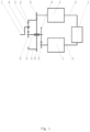
- Fig. 1 shows a schematic diagram of a transmission device with dual-power source according to the invention as claimed, wherein according to an embodiment of the invention as claimed, the transmission device with dual-power source includes a planetary wheel assembly driven by the dual-power source.
- the planetary gear assembly includes a sun gear 3, a rotating inner ring gear 4 and a planet gear 5 meshed/engaged between the sun gear 3 and the rotating inner ring gear 4.
- the dual-power source includes an input shaft 14, a first power source 1 and a second power source 2.
- the input shaft 14 is connected with the sun gear 3; the dual-power source is configured to drive the sun gear 3 to rotate in a first direction relative to its own rotation axis through the input shaft 14.
- the dual-power source is connected with the rotating inner ring gear 4 and drives the rotating inner ring gear 4 to rotate relative to its rotation axis in a second direction opposite to the first direction, at the same time, the planetary gear 5 rotates in the second direction relative to its own rotation axis.
- the rotation direction of the planetary gear 5 around the input shaft 14 depends on the linear speed V1 of the pitch motion of the inner ring gear 4 and the linear speed V2 of the pitch motion of the sun gear 3.
- the first power source 1 is configured to drive the sun gear 3 through the input shaft 14; and the second power source 2 is configured to drive the rotating inner ring gear 4.
- the planetary gear 5 is installed on a planetary gear holder 6.
- An output shaft 7 is arranged on the planetary gear holder 6.
- the sun gear 3 and the rotating inner gear ring 4 are arranged coaxially.
- the output shaft 7 and the input shaft 14 are arranged coaxially.
- the second direction when the first direction is clockwise, the second direction is counterclockwise.
- the first direction when the first direction is counterclockwise, the second direction is clockwise.
- a parallel gear 8 is arranged on the rotating inner ring gear 4.
- An outer ring gear 9 driven by the second power source 2 meshes with the parallel gear 8 to drive the rotating inner ring gear 4.
- the input shaft 14 is provided with a sun wheel front gear 10.
- An input shaft gear 15 driven by the first power source 1 meshes/engages with the sun wheel front gear 10 to drive the sun gear 3.
- Setting the outer ring gear 9 to engage with the parallel gear 8 and setting the input shaft gear 15 to engage with the sun wheel front gear 10 can provide more space for accommodating the first and second power sources, especially when a large power source is required.
- the first power source 1 is a constant power output
- the second power source 2 is a variable speed power output
- An electronic control device 11 is provided to process the error of loss of rotation or instability of the first power source 1 at different power through an input control line 13.
- the movement data of the rotating inner ring gear 4 is transmitted to the electronic control device 11 through a real-time data acquisition line 12 connected with the second power source 2.
- the electronic control device 11 controls and adjusts the power output of the second power source 2 through the real-time data acquisition line 12 under the internal programming or processing of external instructions, so as to make the output shaft 7 reach various speeds required when it is in working condition.
- the first power source 1 is a variable speed power output
- the electronic control device 11 controls the power output of the first power source 1 through the input control line 13.
- the first power source and the second power source are controllable and adjustable power machinery.
- controllable and adjustable power machinery is an electric motor or an internal combustion engine.
- the output shaft 7 can easily rotate forward or reverse (as shown in Fig. 2 ), while the backlash between the teeth is only located on one side, and the force direction between the teeth is also unchanged, so the backlash between the teeth will not be changed due to the frequently changing direction of the output shaft. Because the teeth and teeth are in close mesh on one side only, no impact force caused by backlash conversion is generated. Therefore, the transmission device of the invention as claimed has higher positioning accuracy with longer service life. Moreover, even if there is a large amount of wear between the teeth and the backlash of the teeth is increased, since the other side of the teeth are closely meshed, the perfect positioning accuracy and use effect still can be achieved under the correction control of the electronic control device 11.
- an electric-driven vehicle which includes the transmission device with dual-power source as described in the above embodiments.
- the transmission device with dual-power source according to the invention as claimed is very suitable for the transmission device of pure electric-driven vehicle, wherein the two motors can not only fully operate within the speed range of the highest efficiency of the frequency conversion motor when the frequency is converted, but also the output shaft can be zero speed or positive and negative step less speed change and generates dozens of times more torque than the traditional pure electric-driven vehicle.
- variable frequency motor used in traditional pure electric-driven vehicles must has a large reserve power and has to run in a low efficiency area below 70% of the motor for a long time.
- two dual-power transmission devices with 10kW each can be selected.
- the total power is only 20kW, and the maximum torque can be 9000 N•m to 10000 N•m (as shown in Figure 5 ).
- These two motors can run with 95% high efficiency at the same time.
- the large torque of 9000 N•m or more can completely meet the requirements of pure electric-driven vehicle on any road condition.
- the transmission device according this invention since the motor can always be operated within the high-efficiency operation speed range to avoid the low-efficiency operation speed range, the motor configuration with smaller power rate can be selected under the same road conditions. Therefore, if a traditional pure electric-driven vehicle equips with the dual-power planetary gear transmission device according to the invention as claimed, it can greatly adapt to its driving conditions and greatly extend its driving mileage.
- the dual-power source in this invention can also select a controllable and adjustable high-power internal combustion engine or other power machinery when the transmission device with high power and high torque output is required.
- the invention as claimed is also applied to other mechanical products which requires forward and reverse speed change.
- the attached claims do not claim an assembly method for a transmission device, wherein the transmission device is based on the transmission device as described above.
- the transmission device includes dual-power source which drives a planetary gear assembly.
- the planetary gear assembly includes a sun gear 3, a rotating inner ring gear 4 and a planetary gear 5 engaged between the sun gear 3 and the rotating inner ring gear 4.
- the dual-power source includes an input shaft 14 which is connected with the sun gear 3.
- the dual-power source drives the sun gear 3 to rotate in a first direction relative to its own rotation axis through the input shaft 14.
- the dual-power source is connected with the rotating inner ring gear 4 and drives the rotating inner ring gear 4 to rotate in a second direction opposite to the first direction with respect to its own rotation axis.
- the planetary gear 5 rotates in the second direction with respect to its own rotation axis.
- the rotation direction of the planetary gear 5 around the input shaft 14 depends on the linear speed V1 of the pitch circle motion of the rotating inner ring gear 4 and the linear speed V2 of the pitch circle motion of the sun gear 3.
- the dual-power source includes a first power source 1 and a second power source 2; the first power source 1 drives the sun gear 3 through the input shaft 14; the second power source 2 drives the rotating inner ring gear 4.
- the second direction when the first direction is clockwise, the second direction is counterclockwise; when the first direction is counterclockwise, the second direction is clockwise.
- the second power source 2 drives the rotating inner gear ring 4 to rotate, and transmits the motion data of the rotating inner gear ring 4 to the electronic control device 11 through a real-time data acquisition line 12 connected with the second power source 2.
- the electronic control device 11 controls and adjusts the power output of the second power source 2 through the real-time data acquisition line 12 under the internal programming or processing of external instructions, so as to make the output shaft 7 reach various speeds required when it is in working condition.
- setting the first power source 1 as the adjustable speed power output, and the power output of the first power source 1 is controlled by the electronic control device 11 through the input control line 13.
- setting the first power source and the second power source as controllable and adjustable power machinery.
- controllable and adjustable power machinery is an electric motor or an internal combustion engine.
Landscapes
- Engineering & Computer Science (AREA)
- Mechanical Engineering (AREA)
- General Engineering & Computer Science (AREA)
- Transportation (AREA)
- Chemical & Material Sciences (AREA)
- Combustion & Propulsion (AREA)
- Life Sciences & Earth Sciences (AREA)
- Sustainable Development (AREA)
- Sustainable Energy (AREA)
- Power Engineering (AREA)
- Structure Of Transmissions (AREA)
- Retarders (AREA)
- Hybrid Electric Vehicles (AREA)
- Electric Propulsion And Braking For Vehicles (AREA)
Description
- This invention relates to a transmission device, in particular to a transmission device capable of cooperating with a dual-power source. This invention also relates to an electric-driven vehicle comprising said transmission device with dual-power source and a method of assembly said transmission device with dual-power source.
- Transmissions with planetary gears have tooth surface clearance (also called backlash) which cannot be eliminated, especially when the gears frequently change the direction of movement, which results in shocks, noise, wear and other problems caused by the collision between the teeth, thereby reducing the service life of the transmission and causing inaccurate accuracy during the operation of the transmission. In some high-end products with high precision, miniaturization, large torque and frequent change of output direction, such as RV reducer at each motion joint of industrial robot structure, in order to achieve high positioning accuracy and long service life of RV Reducer, it requires very high-end material selection and high manufacturing accuracy, which will inevitably lead to the increase of manufacturing cost. However, no matter how high the machining accuracy can be achieved, it is impossible to completely eliminate the tooth surface clearance when the teeth are engaged with each other (see
Fig. 3 ). For example, when the planetary gear frequently changes the direction of motion, the fixed inner ring gear tooth surface will be frequently impacted by two forces in different directions. Even if the fit clearance between gears is smaller, the tooth surface clearance between teeth is also frequently converted. As the gears wear, the tooth surface clearance between the teeth will accelerate to expand, which will lead to failure of RV Reducer. - In addition, as is known to all, FM motor is widely used in electric-driven vehicle at present, with high efficiency at high speed, about 94%; but low efficiency at low speed, about 70% (see
Figure 4 ). According to the changes of road conditions, the electric-driven vehicle need to accelerate and decelerate frequently. Every time the electric-driven vehicle run from low speed to high speed, the electric-driven vehicle consumes a lot of electric energy in vain. These consumed electric energy in electric-driven vehicle turns into heat and is taken away by cooling water. - There are also frequency conversion motors for electric-driven vehicle, which are in overload operation when the vehicle starts-up or climbs with a load, the peak value of motor power can reach more than one time of the rated power. The above two problems are the key to the failure of electric-driven vehicle to reach the designed mileage.
- Conventional transmission devices with planetary gear are known from
US2011/212803A1 ,JPH07135701A CN101265961A . - The transmission device with dual-power source according to the invention as claimed can be applied to some high-end products requiring high precision, miniaturization, large torque and frequent change of output direction, such as industrial robot structure, wherein RV Reducer is arranged at each motion joint. The invention as claimed realizes high positioning accuracy and long service life of RV Reducer. In particular, when the planetary gears change the direction of motion frequently, the tooth surface of the rotating inner ring gear will not be impacted by two forces in different directions frequently, and the backlash between teeth will not change frequently. In addition, even if the gear is worn, the backlash between the teeth will not be increased under the speed control of the electronic control device, so as to avoid the failure of RV Reducer.
- In the dual-power transmission device according to the invention as claimed, when the rotation direction of the sun gear, planetary gear and rotating inner ring gear themselves remain unchanged, the output shaft can easily rotate forward or reverse (as shown in
Fig. 2 ), while the backlash between the teeth is only left on one side, and the force direction between the teeth is also unchanged, so the backlash between the teeth will not be changed due to the frequently changing direction of the output shaft. Because the teeth and teeth are in close mesh on only one side, no impact force caused by backlash conversion is generated. Therefore, the transmission device of the invention as claimed has higher positioning accuracy with longer service life. Moreover, even if there is a large amount of wear between the teeth and the backlash of the teeth is increased, since the other side of the teeth are closely meshed, the perfect positioning accuracy and use effect still can be achieved under the correction control of the electronic control device. - The transmission device with dual-power source according to the invention as claimed is also very suitable for the transmission device of pure electric-driven vehicle, wherein the two motors can not only fully operate within the speed range of the highest efficiency of the frequency conversion motor when the frequency is converted, but also the output shaft can be zero speed or positive and negative step less speed change and generates dozens of times more torque than the traditional pure electric-driven vehicle. If a traditional evb320-140-180 variable frequency motor is selected, its rated power is 30kW, peak power is 60kW, and peak torque is only 180 N·M. Because when pure electric-driven vehicle is running, it needs to change speed frequently according to the road conditions, the pure electric-driven vehicle will accelerate from static state to dynamic state for countless times, but also need to go up different slopes and bear different loads. Therefore, the frequency conversion motor used in traditional pure electric-driven vehicles must have a large reserve power and run in a low efficiency area below 70% of the motor for a long time.
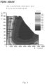
- Under the same road conditions, according to the invention as claimed, two dual-power transmission devices with 10kW each can be selected. The total power is only 20kW, and the maximum torque can be 9000 N·m to 10000 N·m (as shown in
Figure 5 ). These two motors can run with 95% high efficiency at the same time. The large torque of 9000 N·m or more can completely meet the requirements of pure electric-driven vehicle on any road condition. - Having compared the dual-power transmission device with a peak power of 20kW only and a maximum torque of 9000 N·m according this invention with the traditional variable frequency motor with a peak power of 60kW and a peak torque of 180 N·m, it can be concluded that if the transmission device according this invention is adopted, since the motor can always be operated within the high-efficiency operation speed range to avoid the low-efficiency operation speed range, the motor configuration with smaller power rate can be selected under the same road conditions. Therefore, if a traditional pure electric-driven vehicle equips with the dual-power planetary gear transmission device according to this invention, it can greatly adapt to its driving conditions and greatly extend its driving mileage. The dual-power source in this invention can also select the controllable and adjustable high-power internal combustion engine or other power machinery when the transmission device with high power and high torque output is required. The invention as claimed is also applied to other mechanical products which requires forward and reverse speed change.
-
-
Fig. 1 shows a schematic diagram of a transmission device with dual-power source according to the invention as claimed; -
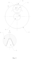
Fig. 2 shows the backlash between the teeth of the rotating inner ring gear and the teeth of the planetary gear when the sun gear rotates in the clockwise direction according to the invention as claimed; -
Fig. 3 shows that there is backlash in the transmission device with conventional planetary wheel assembly in the existing technology; -
Fig. 4 shows a torque diagram of a conventional FM motor; -
Fig. 5 shows a torque diagram of a transmission device with dual-power source according to the invention as claimed. - The embodiments of the invention as claimed will be described in detail below in combination with the accompanying drawings.
-
Fig. 1 shows a schematic diagram of a transmission device with dual-power source according to the invention as claimed, wherein according to an embodiment of the invention as claimed, the transmission device with dual-power source includes a planetary wheel assembly driven by the dual-power source. - The planetary gear assembly includes a
sun gear 3, a rotatinginner ring gear 4 and aplanet gear 5 meshed/engaged between thesun gear 3 and the rotatinginner ring gear 4. - The dual-power source includes an input shaft 14, a
first power source 1 and asecond power source 2. The input shaft 14 is connected with thesun gear 3; the dual-power source is configured to drive thesun gear 3 to rotate in a first direction relative to its own rotation axis through the input shaft 14. The dual-power source is connected with the rotatinginner ring gear 4 and drives the rotatinginner ring gear 4 to rotate relative to its rotation axis in a second direction opposite to the first direction, at the same time, theplanetary gear 5 rotates in the second direction relative to its own rotation axis. The rotation direction of theplanetary gear 5 around the input shaft 14 depends on the linear speed V1 of the pitch motion of theinner ring gear 4 and the linear speed V2 of the pitch motion of thesun gear 3. - According to an embodiment of the invention as claimed, the
first power source 1 is configured to drive thesun gear 3 through the input shaft 14; and thesecond power source 2 is configured to drive the rotatinginner ring gear 4. - According to the above embodiments of the invention as claimed, the
planetary gear 5 is installed on aplanetary gear holder 6. Anoutput shaft 7 is arranged on theplanetary gear holder 6. Thesun gear 3 and the rotatinginner gear ring 4 are arranged coaxially. Theoutput shaft 7 and the input shaft 14 are arranged coaxially. - According to the above embodiments of the invention as claimed, when the first direction is clockwise, the second direction is counterclockwise. When the first direction is counterclockwise, the second direction is clockwise.
- According to the above embodiments of the invention as claimed, when V1 > V2, the rotation direction of the
planetary gear 5 and theplanetary gear holder 6 around the input shaft 14 is opposite to the rotation direction of the input shaft 14, the rotation direction of theoutput shaft 7 itself is opposite to the rotation direction of the input shaft 14, and the tooth surface clearance (also known as backlash) between the tooth surface of theplanetary gear 5 and the teeth surface of the rotatinginner ring gear 4 which meshes with theplanetary gear 5 is only located on one side of the teeth of theplanetary gear 5. For example, as shown inFig. 2 , when the input shaft 14 drives thesun gear 3 to rotate in a clockwise direction relative to its own rotation axis, theoutput shaft 7 itself rotates in a counterclockwise direction, the tooth surface clearance is only located on the right side of the teeth of theplanetary gear 5, and the left side of the teeth of theplanetary gear 5 contacts with the tooth surface of theinner ring gear 4. It can be understood by those skilled in the art that when the input shaft 14 drives thesun gear 3 to rotate in a counter clockwise direction (not shown) relative to its own rotation axis, theoutput shaft 7 itself rotates in a clockwise direction, and the tooth surface clearance is only located on the left side of the teeth of theplanet gear 5, and the right side of the teeth of theplanet gear 5 contacts with the tooth surface of theinner ring gear 4. - When V1 < V2, the rotation direction of the
planetary gear 5 and theplanetary gear holder 6 around the input shaft 14 is the same as the rotation direction of the input shaft 14, the rotation direction of theoutput shaft 7 itself is the same as the rotation direction of the input shaft 14, and the tooth surface clearance between the tooth surface of theplanetary gear 5 and the tooth surface of the rotatinginner ring gear 4 meshed with theplanetary gear 5 is maintained at said side of the teeth ofgear 5. For example, as shown inFig. 2 , when the input shaft 14 drives thesun gear 3 to rotate in a clockwise direction relative to its own rotation axis, theoutput shaft 7 itself rotates in a clockwise direction, the tooth surface clearance is still only located on the right side of the teeth of theplanetary gear 5, and the left side of the teeth of theplanetary gear 5 still contacts with the tooth surface of the rotatinginner ring gear 4. It can be understood by those skilled in the art that when the input shaft 14 drives thesun gear 3 to rotate in the counter clockwise direction (not shown) relative to its own rotation axis, theoutput shaft 7 rotates in the counter clockwise direction, and the tooth surface clearance is still only located on the left side of the teeth of theplanet gear 5, and the right side of the teeth of theplanet gear 5 still contacts with the tooth surfaces of the rotatinginner ring gear 4. - When V1 = V2, the rotation speed of the
planetary gear 5 and theplanetary gear holder 6 around the input shaft 14 is zero, and the rotation speed of theoutput shaft 7 itself is zero. - According to the above embodiments of the invention as claimed, a
parallel gear 8 is arranged on the rotatinginner ring gear 4. Anouter ring gear 9 driven by thesecond power source 2 meshes with theparallel gear 8 to drive the rotatinginner ring gear 4. - According to the above embodiments of the invention as claimed, the input shaft 14 is provided with a sun
wheel front gear 10. Aninput shaft gear 15 driven by thefirst power source 1 meshes/engages with the sunwheel front gear 10 to drive thesun gear 3. - Setting the
outer ring gear 9 to engage with theparallel gear 8 and setting theinput shaft gear 15 to engage with the sunwheel front gear 10 can provide more space for accommodating the first and second power sources, especially when a large power source is required. - According to the above embodiments of the invention as claimed, the
first power source 1 is a constant power output, and thesecond power source 2 is a variable speed power output. An electronic control device 11 is provided to process the error of loss of rotation or instability of thefirst power source 1 at different power through aninput control line 13. - According to the above embodiments of the invention as claimed, when the
second power source 2 drives the rotatinginner ring gear 4 to rotate, the movement data of the rotatinginner ring gear 4 is transmitted to the electronic control device 11 through a real-timedata acquisition line 12 connected with thesecond power source 2. The electronic control device 11 controls and adjusts the power output of thesecond power source 2 through the real-timedata acquisition line 12 under the internal programming or processing of external instructions, so as to make theoutput shaft 7 reach various speeds required when it is in working condition. - According to the above embodiments of the invention as claimed, the
first power source 1 is a variable speed power output, and the electronic control device 11 controls the power output of thefirst power source 1 through theinput control line 13. - Under the correction control of the electronic control device 11, it is also helpful to keep the tooth surface clearance between the tooth surface of the
planetary gear 5 and the tooth surface of the rotatinginner ring gear 4 meshed with theplanetary gear 5 only on one side of the teeth of theplanetary gear 5. - According to the above embodiments of the invention as claimed, the first power source and the second power source are controllable and adjustable power machinery.
- According to the above embodiments of the invention as claimed, the controllable and adjustable power machinery is an electric motor or an internal combustion engine.
- In the dual power transmission device according to the invention as claimed, when the rotation direction of the
sun gear 3,planetary gear 5 and rotatinginner ring gear 4 themselves remain unchanged, theoutput shaft 7 can easily rotate forward or reverse (as shown inFig. 2 ), while the backlash between the teeth is only located on one side, and the force direction between the teeth is also unchanged, so the backlash between the teeth will not be changed due to the frequently changing direction of the output shaft. Because the teeth and teeth are in close mesh on one side only, no impact force caused by backlash conversion is generated. Therefore, the transmission device of the invention as claimed has higher positioning accuracy with longer service life. Moreover, even if there is a large amount of wear between the teeth and the backlash of the teeth is increased, since the other side of the teeth are closely meshed, the perfect positioning accuracy and use effect still can be achieved under the correction control of the electronic control device 11. - According to the invention as claimed, an electric-driven vehicle is also provided, which includes the transmission device with dual-power source as described in the above embodiments.
- The transmission device with dual-power source according to the invention as claimed is very suitable for the transmission device of pure electric-driven vehicle, wherein the two motors can not only fully operate within the speed range of the highest efficiency of the frequency conversion motor when the frequency is converted, but also the output shaft can be zero speed or positive and negative step less speed change and generates dozens of times more torque than the traditional pure electric-driven vehicle.
- If a traditional evb320-140-180 variable frequency motor is selected, its rated power is 30kW, the peak power is 60kW, and the peak torque is only 180 N•M. Because when pure electric-driven vehicle is running, it needs to change speed frequently according to the road conditions, the pure electric-driven vehicle will accelerate from static state to dynamic state for countless times, but also need to climb different slopes and bear different loads, the variable frequency motor used in traditional pure electric-driven vehicles must has a large reserve power and has to run in a low efficiency area below 70% of the motor for a long time.
- Under the same road conditions, according to the invention as claimed, two dual-power transmission devices with 10kW each can be selected. The total power is only 20kW, and the maximum torque can be 9000 N•m to 10000 N•m (as shown in
Figure 5 ). These two motors can run with 95% high efficiency at the same time. The large torque of 9000 N•m or more can completely meet the requirements of pure electric-driven vehicle on any road condition. - Having compared the dual-power transmission device with a peak power of 20kW only and a maximum torque of 9000 N•m according to the invention as claimed with the traditional variable frequency motor with a peak power of 60kW and a peak torque of 180 N•m, it can be concluded that if the transmission device according this invention is adopted, since the motor can always be operated within the high-efficiency operation speed range to avoid the low-efficiency operation speed range, the motor configuration with smaller power rate can be selected under the same road conditions. Therefore, if a traditional pure electric-driven vehicle equips with the dual-power planetary gear transmission device according to the invention as claimed, it can greatly adapt to its driving conditions and greatly extend its driving mileage. The dual-power source in this invention can also select a controllable and adjustable high-power internal combustion engine or other power machinery when the transmission device with high power and high torque output is required. The invention as claimed is also applied to other mechanical products which requires forward and reverse speed change.
- The attached claims do not claim an assembly method for a transmission device, wherein the transmission device is based on the transmission device as described above. The transmission device includes dual-power source which drives a planetary gear assembly. The planetary gear assembly includes a
sun gear 3, a rotatinginner ring gear 4 and aplanetary gear 5 engaged between thesun gear 3 and the rotatinginner ring gear 4. The dual-power source includes an input shaft 14 which is connected with thesun gear 3. The dual-power source drives thesun gear 3 to rotate in a first direction relative to its own rotation axis through the input shaft 14. The dual-power source is connected with the rotatinginner ring gear 4 and drives the rotatinginner ring gear 4 to rotate in a second direction opposite to the first direction with respect to its own rotation axis. At the same time, theplanetary gear 5 rotates in the second direction with respect to its own rotation axis. The rotation direction of theplanetary gear 5 around the input shaft 14 depends on the linear speed V1 of the pitch circle motion of the rotatinginner ring gear 4 and the linear speed V2 of the pitch circle motion of thesun gear 3. - According to an embodiment of the assembly method as described above, the dual-power source includes a
first power source 1 and asecond power source 2; thefirst power source 1 drives thesun gear 3 through the input shaft 14; thesecond power source 2 drives the rotatinginner ring gear 4. - According to various embodiments of the assembly method described above, installing the
planetary gear 5 on theplanetary gear holder 6; arranging theoutput shaft 7 on theplanetary gear holder 6; setting thesun gear 3 and the rotatinginner gear ring 4 coaxially; setting theoutput shaft 7 and the input shaft 14 coaxially. - According to various embodiments of the assembly method described above, when the first direction is clockwise, the second direction is counterclockwise; when the first direction is counterclockwise, the second direction is clockwise.
- According to various embodiments of the assembly method as described above, when V1 > V2, the rotation direction of the
planetary gear 5 and theplanetary gear holder 6 around the input shaft 14 is opposite to the rotation direction of the input shaft 14, the rotation direction of theoutput shaft 7 itself is opposite to the rotation direction of the input shaft 14, and the tooth surface clearance (also known as backlash) between the tooth surface of theplanetary gear 5 and the teeth surface of the rotatinginner ring gear 4 which meshes with theplanetary gear 5 is only located on one side of the teeth of theplanetary gear 5. It can be understood by those skilled in the art that when the input shaft 14 drives thesun gear 3 to rotate in a counter clockwise direction (not shown) relative to its own rotation axis, theoutput shaft 7 rotates in a clockwise direction, and the tooth surface clearance is only located on the left side of the teeth of theplanet gear 5, while the right side of the teeth of theplanet gear 5 contacts with the tooth surface of theinner ring gear 4. - When V1 < V2, the rotation direction of the
planetary gear 5 and theplanetary gear holder 6 around the input shaft 14 is the same as the rotation direction of the input shaft 14, the rotation direction of theoutput shaft 7 itself is the same as the rotation direction of the input shaft 14, and the tooth surface clearance between the tooth surface of theplanetary gear 5 and the tooth surface of the rotatinginner ring gear 4 meshed with theplanetary gear 5 is maintained at said side of the teeth ofgear 5. It can be understood by those skilled in the art that when the input shaft 14 drives thesun gear 3 to rotate in the counter clockwise direction (not shown) relative to its own rotation axis, theoutput shaft 7 rotates in the counter clockwise direction, and the tooth surface clearance is still located on the left side of the teeth of theplanet gear 5 only, while the right side of the teeth of theplanet gear 5 still contacts with the tooth surfaces of the rotatinginner ring gear 4. - When V1 = V2, the rotation speed of the
planetary gear 5 and theplanetary gear holder 6 around the input shaft 14 is zero, and the rotation speed of theoutput shaft 7 itself is zero. - According to various embodiments of the assembly method as described above, setting the
first power source 1 as constant power output, and setting thesecond power source 2 as variable speed power output; providing an electronic control device 11; the electronic control device 11 processes the error of loss of rotation or instability of thefirst power source 1 at different powers through aninput control line 13. - According to various embodiments of the assembly method described above, the
second power source 2 drives the rotatinginner gear ring 4 to rotate, and transmits the motion data of the rotatinginner gear ring 4 to the electronic control device 11 through a real-timedata acquisition line 12 connected with thesecond power source 2. The electronic control device 11 controls and adjusts the power output of thesecond power source 2 through the real-timedata acquisition line 12 under the internal programming or processing of external instructions, so as to make theoutput shaft 7 reach various speeds required when it is in working condition. - According to various embodiments of the assembly method described above, setting the
first power source 1 as the adjustable speed power output, and the power output of thefirst power source 1 is controlled by the electronic control device 11 through theinput control line 13. - According to various embodiments of the assembly method described above, arranging a
parallel gear 8 on the rotatinginner ring gear 4; anouter ring gear 9 driven by thesecond power source 2 engages with theparallel gear 8 to drive the rotatinginner ring gear 4. - According to various embodiments of the assembly method described above, arranging a sun
wheel front gear 10 on the input shaft 14; aninput shaft gear 15 driven by thefirst power source 1 engages with the front sunwheel front gear 10 so as to drive thesun gear 3. - According to various embodiments of the assembly method described above, setting the first power source and the second power source as controllable and adjustable power machinery.
- According to various embodiments of the drive method described above, the controllable and adjustable power machinery is an electric motor or an internal combustion engine.
Claims (6)
- A transmission device with a dual-power source, whereinthe dual power source includes a first power source (1) and a second power source (2);the transmission device includes a planetary gear assembly driven by the dual-power source, the planetary gear assembly includes a sun gear (3), a rotating inner ring gear (4) and a planetary gear (5) engaged between the sun gear (3) and the rotating inner ring gear (4);the dual-power source includes an input shaft (14);one end of the input shaft (14) is connected with the sun gear (3);the dual-power source is configured to drive the sun gear (3) to rotate in a first direction with respect to its own rotation axis through the input shaft (14);the rotating inner ring gear (4) includes a tooth surface (16) and a parallel gear (8);the dual-power source is connected with the rotating inner ring gear (4) and drives the rotating inner ring gear (4) to rotate in a second direction opposite to the first direction with respect to its own rotation axis, at the same time, the planetary gear (5) rotates in the second direction with respect to its own rotation axis;the rotation direction of the planetary gear (5) around the input shaft (14) depends on the linear speed V1 of pitch circle motion of the rotating inner ring gear (4) and the linear speed V2 of pitch circle motion of the sun gear (3),wherebythe parallel gear (8) is arranged on the rotating inner gear ring (4);an outer ring gear (9) driven by the second power source (2) is engaged with the parallel gear (8) to drive the rotating inner ring gear (4);a sun wheel front gear (10) is arranged on another end of the input shaft (14);an input shaft gear (15) driven by the first power source (1) is engaged with the sun wheel front gear (10) to drive the sun gear (3);the input shaft (14) is arranged to pass through the rotating inner ring gear (4); andthe sun gear (3) is located on one side of the rotating inner ring gear (4) and the sun wheel front gear (10) is located on another side of the rotating inner ring gear (4), wherein the sun gear (3) is connected with the sun wheel front gear (10) through the input shaft (14) only;wherein, in an axial direction along the input shaft (14), the sun wheel front gear (10) is disposed between the rotating inner ring gear (4) and the first power source (1) and between the rotating inner ring gear (4) and the second power source (2); andwherein the tooth surface (16) and the parallel gear (8) are separated in the axial direction along the input shaft (14), and the parallel gear (8) is disposed between the sun gear (3) and the sun gear front gear (10) in the axial direction along the input shaft (14);the first power source (1) is a constant power output, and the second power source (2) is a variable speed power output;an electronic control device (11) is connected with the first power source (1) through an input control line (13);the electronic control device (11) is connected with the second power source (2) through a real-time data acquisition line (12);the transmission device is configured such that when the second power source (2) drives the rotating inner ring gear (4) to rotate, the movement data of the rotating inner ring gear (4) is transmitted to the electronic control device (11);the transmission device is further configured such that the electronic control device (11) controls and adjusts the power output of the second power source (2) under the internal programming or processing of external instructions, so as to make the output shaft (7) reach various speeds required when it is in working condition.
- The transmission device with the dual-power source according to claim 1, whereinthe planet gear (5) is installed on a planetary gear holder (6);an output shaft (7) is arranged on the planetary gear holder (6);the sun gear (3) and the rotating inner gear ring (4) are arranged coaxially;the output shaft (7) and the input shaft (14) are arranged coaxially.
- The transmission device with the dual-power source according to claim 2, wherein
the electronic control device (11) controls the power output of the first power source (1) through an input control line (13). - The transmission device with the dual-power source according to claim 3, wherein
the second power source (2) is controllable and adjustable power machinery. - The transmission device with the dual-power source according to claim 4, wherein the controllable and adjustable power machinery is an electric motor or an internal combustion engine.
- An electric-driven vehicle, which includes a transmission device with a dual-power source according to claim 1.
Applications Claiming Priority (1)
| Application Number | Priority Date | Filing Date | Title |
|---|---|---|---|
| PCT/CN2017/098837 WO2019037030A1 (en) | 2017-08-24 | 2017-08-24 | TRANSMISSION DEVICE, ELECTRIC VEHICLE COMPRISING DEVICE AND DEVICE DRIVING METHOD |
Publications (3)
| Publication Number | Publication Date |
|---|---|
| EP3666571A1 EP3666571A1 (en) | 2020-06-17 |
| EP3666571A4 EP3666571A4 (en) | 2021-08-18 |
| EP3666571B1 true EP3666571B1 (en) | 2025-04-30 |
Family
ID=65438580
Family Applications (1)
| Application Number | Title | Priority Date | Filing Date |
|---|---|---|---|
| EP17922906.7A Active EP3666571B1 (en) | 2017-08-24 | 2017-08-24 | TRANSMISSION DEVICE, ELECTRIC VEHICLE WITH THE DEVICE AND METHOD FOR CONTROLLING THE DEVICE |
Country Status (5)
| Country | Link |
|---|---|
| US (3) | US20210262551A1 (en) |
| EP (1) | EP3666571B1 (en) |
| JP (2) | JP7371869B2 (en) |
| KR (2) | KR20220003160A (en) |
| WO (1) | WO2019037030A1 (en) |
Families Citing this family (1)
| Publication number | Priority date | Publication date | Assignee | Title |
|---|---|---|---|---|
| KR102333212B1 (en) * | 2020-06-01 | 2021-11-30 | 이길석 | Vehicle transmission system |
Family Cites Families (22)
| Publication number | Priority date | Publication date | Assignee | Title |
|---|---|---|---|---|
| US5195600A (en) * | 1991-07-11 | 1993-03-23 | General Electric Company | Electric drive system for track-laying vehicles |
| US5295925A (en) * | 1991-11-22 | 1994-03-22 | Harmonic Drive Systems, Inc. | Planetary gear transmission |
| JP3291871B2 (en) * | 1993-11-10 | 2002-06-17 | 株式会社エクォス・リサーチ | Hybrid vehicle |
| JPH08298748A (en) * | 1995-04-25 | 1996-11-12 | Shigeto Suzuki | Motor apparatus |
| US7465251B2 (en) * | 2004-07-10 | 2008-12-16 | Lingling Zhang | Hybrid electric vehicle |
| JP2006132595A (en) * | 2004-11-02 | 2006-05-25 | Nissan Motor Co Ltd | Automatic transmission for vehicles |
| KR20090064220A (en) | 2007-12-15 | 2009-06-18 | 현대자동차주식회사 | Vehicle Reduction Device and Electronic Parking Brake and Electronic Motor Brake |
| CN101265961A (en) * | 2008-04-16 | 2008-09-17 | 大连橡胶塑料机械股份有限公司 | Large-sized squeezing granulation units main reducing gear infinite speed-changing device |
| US8142318B2 (en) * | 2008-08-13 | 2012-03-27 | Palmer Denis L | Apparatus, system, and method for a variable ratio transmission |
| DE102009036992A1 (en) * | 2009-08-12 | 2011-02-17 | Benteler Automobiltechnik Gmbh | Drive for a vehicle and method for driving a vehicle |
| US8414438B2 (en) * | 2009-11-12 | 2013-04-09 | Magna Powertrain, Inc. | Variable ratio epicyclic gear drives |
| CN102133856A (en) * | 2010-01-25 | 2011-07-27 | 北京理工大学 | Dual-motor rotating speed coupling drive assembly |
| JP5212756B2 (en) * | 2010-12-27 | 2013-06-19 | 株式会社デンソー | Vehicle power output device and vehicle |
| WO2012090019A1 (en) | 2010-12-30 | 2012-07-05 | Renault Trucks | Dual drive arrangement for the drive of a vehicle hydraulic pump and method of controlling the same |
| FR3005607B1 (en) * | 2013-05-16 | 2016-11-18 | Technoboost | HYDRAULIC HYBRID VEHICLE TRANSMISSION HAVING A PLANETARY TRAIN CONNECTED TO A PUMP BY A SPEED REDUCER |
| CN103754099A (en) * | 2014-01-13 | 2014-04-30 | 北京理工大学 | Double-motor multi-mode dynamic coupling driving assembly |
| CN105150819B (en) * | 2015-09-10 | 2018-11-27 | 福建万润新能源科技有限公司 | A kind of electric car double-motor power device |
| CN105034782B (en) * | 2015-09-10 | 2018-09-14 | 福建万润新能源科技有限公司 | A kind of electric vehicle multi-mode dynamical system |
| US20170151875A1 (en) * | 2015-11-30 | 2017-06-01 | Faraday&Future Inc. | Detecting position measurement errors in an electric motor system |
| EP3420248A1 (en) | 2015-12-22 | 2019-01-02 | Robert Bosch GmbH | A transmission system for a vehicle |
| CN106015499A (en) * | 2016-07-07 | 2016-10-12 | 洛阳天迈传动科技有限公司 | Dual-motor driven infinitely variable transmission |
| CN206938435U (en) * | 2017-03-30 | 2018-01-30 | 上海尊阶士工程技术有限公司 | A kind of dynamical system hybrid power, pure electric transmission machanism |
-
2017
- 2017-08-24 KR KR1020217043132A patent/KR20220003160A/en not_active Ceased
- 2017-08-24 EP EP17922906.7A patent/EP3666571B1/en active Active
- 2017-08-24 US US16/641,627 patent/US20210262551A1/en not_active Abandoned
- 2017-08-24 WO PCT/CN2017/098837 patent/WO2019037030A1/en not_active Ceased
- 2017-08-24 JP JP2020531800A patent/JP7371869B2/en active Active
- 2017-08-24 KR KR1020207008402A patent/KR20200041369A/en not_active Ceased
-
2021
- 2021-04-28 US US17/243,569 patent/US20210246970A1/en not_active Abandoned
- 2021-07-29 US US17/389,328 patent/US11598392B2/en active Active
-
2023
- 2023-03-24 JP JP2023048213A patent/JP7651131B2/en active Active
Also Published As
| Publication number | Publication date |
|---|---|
| JP2023089013A (en) | 2023-06-27 |
| JP2020531772A (en) | 2020-11-05 |
| US20210356019A1 (en) | 2021-11-18 |
| EP3666571A4 (en) | 2021-08-18 |
| WO2019037030A1 (en) | 2019-02-28 |
| US20210262551A1 (en) | 2021-08-26 |
| US11598392B2 (en) | 2023-03-07 |
| US20210246970A1 (en) | 2021-08-12 |
| KR20200041369A (en) | 2020-04-21 |
| JP7371869B2 (en) | 2023-10-31 |
| EP3666571A1 (en) | 2020-06-17 |
| JP7651131B2 (en) | 2025-03-26 |
| KR20220003160A (en) | 2022-01-07 |
Similar Documents
| Publication | Publication Date | Title |
|---|---|---|
| CN104565333A (en) | Method for automatically eliminating limited angle gear backlash | |
| US20140349801A1 (en) | Gearing Device With An Internally Toothed Internal Gear And Two Spur Gears Meshing Therewith | |
| CN104343895A (en) | Self-compensating zero backlash planetary transmission reducer | |
| US11598392B2 (en) | Transmission device, electric vehicle comprising device, and method for driving device | |
| CN116398617A (en) | A backlash elimination method for a torque reduction motor module | |
| US11440181B2 (en) | Planetary gear train, gearbox and industrial robot | |
| HK40026578A (en) | Transmission device, electric vehicle comprising device, and method for driving device | |
| CN109469714B (en) | Two-gear automatic speed-changing electric driving wheel assembly | |
| CN109826912B (en) | Transmission device, electric vehicle comprising the device and method for driving the device | |
| EP3584467A1 (en) | Loader three-stage hydraulic mechanical stepless transmission device | |
| CN204153064U (en) | A kind of self compensation zero back clearance planetary transmission retarder | |
| KR200468990Y1 (en) | Idle gear carrier of speed reducer | |
| KR20210074594A (en) | Actuator for shift by wire system | |
| CN104989816B (en) | A kind of dual input list exports constant rotational speed control system | |
| CN207814350U (en) | A kind of intelligent robot reducer structure | |
| CN101213388A (en) | Transistor type universal drive | |
| KR101691307B1 (en) | Planetary gear reducer | |
| CN209762153U (en) | Dual-power transmission with CVT (continuously variable transmission) | |
| CN222596707U (en) | Speed reducing mechanism | |
| US20240263618A1 (en) | Electric power generating device | |
| CN104806705A (en) | Gear reducer | |
| CN1074515C (en) | Optional tooth number complex conjugate tooth pin-wheel gearing device | |
| CN221237118U (en) | Planetary gears, transmission mechanisms and power devices | |
| EP4394206B1 (en) | Reduction group | |
| CN224191770U (en) | Speed reducing motor with adjustable back clearance |
Legal Events
| Date | Code | Title | Description |
|---|---|---|---|
| STAA | Information on the status of an ep patent application or granted ep patent |
Free format text: STATUS: THE INTERNATIONAL PUBLICATION HAS BEEN MADE |
|
| PUAI | Public reference made under article 153(3) epc to a published international application that has entered the european phase |
Free format text: ORIGINAL CODE: 0009012 |
|
| STAA | Information on the status of an ep patent application or granted ep patent |
Free format text: STATUS: REQUEST FOR EXAMINATION WAS MADE |
|
| 17P | Request for examination filed |
Effective date: 20200310 |
|
| AK | Designated contracting states |
Kind code of ref document: A1 Designated state(s): AL AT BE BG CH CY CZ DE DK EE ES FI FR GB GR HR HU IE IS IT LI LT LU LV MC MK MT NL NO PL PT RO RS SE SI SK SM TR |
|
| AX | Request for extension of the european patent |
Extension state: BA ME |
|
| DAV | Request for validation of the european patent (deleted) | ||
| DAX | Request for extension of the european patent (deleted) | ||
| REG | Reference to a national code |
Ref country code: HK Ref legal event code: DE Ref document number: 40026578 Country of ref document: HK |
|
| A4 | Supplementary search report drawn up and despatched |
Effective date: 20210720 |
|
| RIC1 | Information provided on ipc code assigned before grant |
Ipc: B60K 1/02 20060101AFI20210714BHEP |
|
| STAA | Information on the status of an ep patent application or granted ep patent |
Free format text: STATUS: EXAMINATION IS IN PROGRESS |
|
| 17Q | First examination report despatched |
Effective date: 20230809 |
|
| GRAP | Despatch of communication of intention to grant a patent |
Free format text: ORIGINAL CODE: EPIDOSNIGR1 |
|
| STAA | Information on the status of an ep patent application or granted ep patent |
Free format text: STATUS: GRANT OF PATENT IS INTENDED |
|
| RIC1 | Information provided on ipc code assigned before grant |
Ipc: F16H 3/72 20060101ALI20241112BHEP Ipc: B60K 1/02 20060101AFI20241112BHEP |
|
| INTG | Intention to grant announced |
Effective date: 20241202 |
|
| GRAS | Grant fee paid |
Free format text: ORIGINAL CODE: EPIDOSNIGR3 |
|
| GRAA | (expected) grant |
Free format text: ORIGINAL CODE: 0009210 |
|
| STAA | Information on the status of an ep patent application or granted ep patent |
Free format text: STATUS: THE PATENT HAS BEEN GRANTED |
|
| AK | Designated contracting states |
Kind code of ref document: B1 Designated state(s): AL AT BE BG CH CY CZ DE DK EE ES FI FR GB GR HR HU IE IS IT LI LT LU LV MC MK MT NL NO PL PT RO RS SE SI SK SM TR |
|
| REG | Reference to a national code |
Ref country code: CH Ref legal event code: EP Ref country code: GB Ref legal event code: FG4D |
|
| REG | Reference to a national code |
Ref country code: IE Ref legal event code: FG4D |
|
| REG | Reference to a national code |
Ref country code: DE Ref legal event code: R096 Ref document number: 602017089257 Country of ref document: DE |
|
| REG | Reference to a national code |
Ref country code: NL Ref legal event code: MP Effective date: 20250430 |
|
| REG | Reference to a national code |
Ref country code: AT Ref legal event code: MK05 Ref document number: 1789733 Country of ref document: AT Kind code of ref document: T Effective date: 20250430 |
|
| PG25 | Lapsed in a contracting state [announced via postgrant information from national office to epo] |
Ref country code: FI Free format text: LAPSE BECAUSE OF FAILURE TO SUBMIT A TRANSLATION OF THE DESCRIPTION OR TO PAY THE FEE WITHIN THE PRESCRIBED TIME-LIMIT Effective date: 20250430 Ref country code: PT Free format text: LAPSE BECAUSE OF FAILURE TO SUBMIT A TRANSLATION OF THE DESCRIPTION OR TO PAY THE FEE WITHIN THE PRESCRIBED TIME-LIMIT Effective date: 20250901 Ref country code: ES Free format text: LAPSE BECAUSE OF FAILURE TO SUBMIT A TRANSLATION OF THE DESCRIPTION OR TO PAY THE FEE WITHIN THE PRESCRIBED TIME-LIMIT Effective date: 20250430 |
|
| PGFP | Annual fee paid to national office [announced via postgrant information from national office to epo] |
Ref country code: DE Payment date: 20250819 Year of fee payment: 9 |
|
| REG | Reference to a national code |
Ref country code: LT Ref legal event code: MG9D |
|
| PG25 | Lapsed in a contracting state [announced via postgrant information from national office to epo] |
Ref country code: GR Free format text: LAPSE BECAUSE OF FAILURE TO SUBMIT A TRANSLATION OF THE DESCRIPTION OR TO PAY THE FEE WITHIN THE PRESCRIBED TIME-LIMIT Effective date: 20250731 Ref country code: NO Free format text: LAPSE BECAUSE OF FAILURE TO SUBMIT A TRANSLATION OF THE DESCRIPTION OR TO PAY THE FEE WITHIN THE PRESCRIBED TIME-LIMIT Effective date: 20250730 |
|
| PG25 | Lapsed in a contracting state [announced via postgrant information from national office to epo] |
Ref country code: PL Free format text: LAPSE BECAUSE OF FAILURE TO SUBMIT A TRANSLATION OF THE DESCRIPTION OR TO PAY THE FEE WITHIN THE PRESCRIBED TIME-LIMIT Effective date: 20250430 Ref country code: NL Free format text: LAPSE BECAUSE OF FAILURE TO SUBMIT A TRANSLATION OF THE DESCRIPTION OR TO PAY THE FEE WITHIN THE PRESCRIBED TIME-LIMIT Effective date: 20250430 |
|
| PGFP | Annual fee paid to national office [announced via postgrant information from national office to epo] |
Ref country code: IT Payment date: 20250827 Year of fee payment: 9 |
|
| PG25 | Lapsed in a contracting state [announced via postgrant information from national office to epo] |
Ref country code: BG Free format text: LAPSE BECAUSE OF FAILURE TO SUBMIT A TRANSLATION OF THE DESCRIPTION OR TO PAY THE FEE WITHIN THE PRESCRIBED TIME-LIMIT Effective date: 20250430 |
|
| PGFP | Annual fee paid to national office [announced via postgrant information from national office to epo] |
Ref country code: GB Payment date: 20250814 Year of fee payment: 9 |
|
| PG25 | Lapsed in a contracting state [announced via postgrant information from national office to epo] |
Ref country code: HR Free format text: LAPSE BECAUSE OF FAILURE TO SUBMIT A TRANSLATION OF THE DESCRIPTION OR TO PAY THE FEE WITHIN THE PRESCRIBED TIME-LIMIT Effective date: 20250430 |
|
| PG25 | Lapsed in a contracting state [announced via postgrant information from national office to epo] |
Ref country code: AT Free format text: LAPSE BECAUSE OF FAILURE TO SUBMIT A TRANSLATION OF THE DESCRIPTION OR TO PAY THE FEE WITHIN THE PRESCRIBED TIME-LIMIT Effective date: 20250430 |
|
| PGFP | Annual fee paid to national office [announced via postgrant information from national office to epo] |
Ref country code: FR Payment date: 20250821 Year of fee payment: 9 |
|
| PG25 | Lapsed in a contracting state [announced via postgrant information from national office to epo] |
Ref country code: RS Free format text: LAPSE BECAUSE OF FAILURE TO SUBMIT A TRANSLATION OF THE DESCRIPTION OR TO PAY THE FEE WITHIN THE PRESCRIBED TIME-LIMIT Effective date: 20250731 |
|
| PG25 | Lapsed in a contracting state [announced via postgrant information from national office to epo] |
Ref country code: IS Free format text: LAPSE BECAUSE OF FAILURE TO SUBMIT A TRANSLATION OF THE DESCRIPTION OR TO PAY THE FEE WITHIN THE PRESCRIBED TIME-LIMIT Effective date: 20250830 |
|
| P01 | Opt-out of the competence of the unified patent court (upc) registered |
Free format text: CASE NUMBER: UPC_APP_7493_3666571/2025 Effective date: 20250918 |
|
| PG25 | Lapsed in a contracting state [announced via postgrant information from national office to epo] |
Ref country code: LV Free format text: LAPSE BECAUSE OF FAILURE TO SUBMIT A TRANSLATION OF THE DESCRIPTION OR TO PAY THE FEE WITHIN THE PRESCRIBED TIME-LIMIT Effective date: 20250430 |
|
| PG25 | Lapsed in a contracting state [announced via postgrant information from national office to epo] |
Ref country code: DK Free format text: LAPSE BECAUSE OF FAILURE TO SUBMIT A TRANSLATION OF THE DESCRIPTION OR TO PAY THE FEE WITHIN THE PRESCRIBED TIME-LIMIT Effective date: 20250430 Ref country code: SM Free format text: LAPSE BECAUSE OF FAILURE TO SUBMIT A TRANSLATION OF THE DESCRIPTION OR TO PAY THE FEE WITHIN THE PRESCRIBED TIME-LIMIT Effective date: 20250430 |
|
| PG25 | Lapsed in a contracting state [announced via postgrant information from national office to epo] |
Ref country code: CZ Free format text: LAPSE BECAUSE OF FAILURE TO SUBMIT A TRANSLATION OF THE DESCRIPTION OR TO PAY THE FEE WITHIN THE PRESCRIBED TIME-LIMIT Effective date: 20250430 |
|
| PG25 | Lapsed in a contracting state [announced via postgrant information from national office to epo] |
Ref country code: EE Free format text: LAPSE BECAUSE OF FAILURE TO SUBMIT A TRANSLATION OF THE DESCRIPTION OR TO PAY THE FEE WITHIN THE PRESCRIBED TIME-LIMIT Effective date: 20250430 |
|
| PG25 | Lapsed in a contracting state [announced via postgrant information from national office to epo] |
Ref country code: RO Free format text: LAPSE BECAUSE OF FAILURE TO SUBMIT A TRANSLATION OF THE DESCRIPTION OR TO PAY THE FEE WITHIN THE PRESCRIBED TIME-LIMIT Effective date: 20250430 Ref country code: SK Free format text: LAPSE BECAUSE OF FAILURE TO SUBMIT A TRANSLATION OF THE DESCRIPTION OR TO PAY THE FEE WITHIN THE PRESCRIBED TIME-LIMIT Effective date: 20250430 |
|
| REG | Reference to a national code |
Ref country code: DE Ref legal event code: R097 Ref document number: 602017089257 Country of ref document: DE |
|
| PLBE | No opposition filed within time limit |
Free format text: ORIGINAL CODE: 0009261 |
|
| STAA | Information on the status of an ep patent application or granted ep patent |
Free format text: STATUS: NO OPPOSITION FILED WITHIN TIME LIMIT |
|
| REG | Reference to a national code |
Ref country code: CH Ref legal event code: L10 Free format text: ST27 STATUS EVENT CODE: U-0-0-L10-L00 (AS PROVIDED BY THE NATIONAL OFFICE) Effective date: 20260311 |
|
| REG | Reference to a national code |
Ref country code: CH Ref legal event code: H13 Free format text: ST27 STATUS EVENT CODE: U-0-0-H10-H13 (AS PROVIDED BY THE NATIONAL OFFICE) Effective date: 20260324 |
|
| PG25 | Lapsed in a contracting state [announced via postgrant information from national office to epo] |
Ref country code: MC Free format text: LAPSE BECAUSE OF FAILURE TO SUBMIT A TRANSLATION OF THE DESCRIPTION OR TO PAY THE FEE WITHIN THE PRESCRIBED TIME-LIMIT Effective date: 20250430 |
|
| 26N | No opposition filed |
Effective date: 20260202 |
|
| PG25 | Lapsed in a contracting state [announced via postgrant information from national office to epo] |
Ref country code: LU Free format text: LAPSE BECAUSE OF NON-PAYMENT OF DUE FEES Effective date: 20250824 |
|
| PG25 | Lapsed in a contracting state [announced via postgrant information from national office to epo] |
Ref country code: CH Free format text: LAPSE BECAUSE OF NON-PAYMENT OF DUE FEES Effective date: 20250831 |