EP3666496B1 - Verfahren zur herstellung eines kunststofftanks - Google Patents
Verfahren zur herstellung eines kunststofftanks Download PDFInfo
- Publication number
- EP3666496B1 EP3666496B1 EP18211294.6A EP18211294A EP3666496B1 EP 3666496 B1 EP3666496 B1 EP 3666496B1 EP 18211294 A EP18211294 A EP 18211294A EP 3666496 B1 EP3666496 B1 EP 3666496B1
- Authority
- EP
- European Patent Office
- Prior art keywords
- tank wall
- stiffening profile
- tank
- plastic
- stiffening
- Prior art date
- Legal status (The legal status is an assumption and is not a legal conclusion. Google has not performed a legal analysis and makes no representation as to the accuracy of the status listed.)
- Active
Links
Images
Classifications
-
- B—PERFORMING OPERATIONS; TRANSPORTING
- B29—WORKING OF PLASTICS; WORKING OF SUBSTANCES IN A PLASTIC STATE IN GENERAL
- B29C—SHAPING OR JOINING OF PLASTICS; SHAPING OF MATERIAL IN A PLASTIC STATE, NOT OTHERWISE PROVIDED FOR; AFTER-TREATMENT OF THE SHAPED PRODUCTS, e.g. REPAIRING
- B29C33/00—Moulds or cores; Details thereof or accessories therefor
- B29C33/12—Moulds or cores; Details thereof or accessories therefor with incorporated means for positioning inserts, e.g. labels
- B29C33/14—Moulds or cores; Details thereof or accessories therefor with incorporated means for positioning inserts, e.g. labels against the mould wall
- B29C33/18—Moulds or cores; Details thereof or accessories therefor with incorporated means for positioning inserts, e.g. labels against the mould wall using vacuum
-
- B—PERFORMING OPERATIONS; TRANSPORTING
- B29—WORKING OF PLASTICS; WORKING OF SUBSTANCES IN A PLASTIC STATE IN GENERAL
- B29C—SHAPING OR JOINING OF PLASTICS; SHAPING OF MATERIAL IN A PLASTIC STATE, NOT OTHERWISE PROVIDED FOR; AFTER-TREATMENT OF THE SHAPED PRODUCTS, e.g. REPAIRING
- B29C65/00—Joining or sealing of preformed parts, e.g. welding of plastics materials; Apparatus therefor
- B29C65/70—Joining or sealing of preformed parts, e.g. welding of plastics materials; Apparatus therefor by moulding
-
- B—PERFORMING OPERATIONS; TRANSPORTING
- B60—VEHICLES IN GENERAL
- B60K—ARRANGEMENT OR MOUNTING OF PROPULSION UNITS OR OF TRANSMISSIONS IN VEHICLES; ARRANGEMENT OR MOUNTING OF PLURAL DIVERSE PRIME-MOVERS IN VEHICLES; AUXILIARY DRIVES FOR VEHICLES; INSTRUMENTATION OR DASHBOARDS FOR VEHICLES; ARRANGEMENTS IN CONNECTION WITH COOLING, AIR INTAKE, GAS EXHAUST OR FUEL SUPPLY OF PROPULSION UNITS IN VEHICLES
- B60K15/00—Arrangement in connection with fuel supply of combustion engines or other fuel consuming energy converters, e.g. fuel cells; Mounting or construction of fuel tanks
- B60K15/03—Fuel tanks
-
- B—PERFORMING OPERATIONS; TRANSPORTING
- B29—WORKING OF PLASTICS; WORKING OF SUBSTANCES IN A PLASTIC STATE IN GENERAL
- B29C—SHAPING OR JOINING OF PLASTICS; SHAPING OF MATERIAL IN A PLASTIC STATE, NOT OTHERWISE PROVIDED FOR; AFTER-TREATMENT OF THE SHAPED PRODUCTS, e.g. REPAIRING
- B29C49/00—Blow-moulding, i.e. blowing a preform or parison to a desired shape within a mould; Apparatus therefor
- B29C49/02—Combined blow-moulding and manufacture of the preform or the parison
- B29C49/04—Extrusion blow-moulding
- B29C49/04102—Extrusion blow-moulding extruding the material continuously
-
- B—PERFORMING OPERATIONS; TRANSPORTING
- B29—WORKING OF PLASTICS; WORKING OF SUBSTANCES IN A PLASTIC STATE IN GENERAL
- B29C—SHAPING OR JOINING OF PLASTICS; SHAPING OF MATERIAL IN A PLASTIC STATE, NOT OTHERWISE PROVIDED FOR; AFTER-TREATMENT OF THE SHAPED PRODUCTS, e.g. REPAIRING
- B29C49/00—Blow-moulding, i.e. blowing a preform or parison to a desired shape within a mould; Apparatus therefor
- B29C49/20—Blow-moulding, i.e. blowing a preform or parison to a desired shape within a mould; Apparatus therefor of articles having inserts or reinforcements ; Handling of inserts or reinforcements
-
- B—PERFORMING OPERATIONS; TRANSPORTING
- B29—WORKING OF PLASTICS; WORKING OF SUBSTANCES IN A PLASTIC STATE IN GENERAL
- B29C—SHAPING OR JOINING OF PLASTICS; SHAPING OF MATERIAL IN A PLASTIC STATE, NOT OTHERWISE PROVIDED FOR; AFTER-TREATMENT OF THE SHAPED PRODUCTS, e.g. REPAIRING
- B29C65/00—Joining or sealing of preformed parts, e.g. welding of plastics materials; Apparatus therefor
- B29C65/78—Means for handling the parts to be joined, e.g. for making containers or hollow articles, e.g. means for handling sheets, plates, web-like materials, tubular articles, hollow articles or elements to be joined therewith; Means for discharging the joined articles from the joining apparatus
- B29C65/7841—Holding or clamping means for handling purposes
- B29C65/7847—Holding or clamping means for handling purposes using vacuum to hold at least one of the parts to be joined
-
- B—PERFORMING OPERATIONS; TRANSPORTING
- B29—WORKING OF PLASTICS; WORKING OF SUBSTANCES IN A PLASTIC STATE IN GENERAL
- B29C—SHAPING OR JOINING OF PLASTICS; SHAPING OF MATERIAL IN A PLASTIC STATE, NOT OTHERWISE PROVIDED FOR; AFTER-TREATMENT OF THE SHAPED PRODUCTS, e.g. REPAIRING
- B29C70/00—Shaping composites, i.e. plastics material comprising reinforcements, fillers or preformed parts, e.g. inserts
- B29C70/04—Shaping composites, i.e. plastics material comprising reinforcements, fillers or preformed parts, e.g. inserts comprising reinforcements only, e.g. self-reinforcing plastics
- B29C70/28—Shaping operations therefor
- B29C70/40—Shaping or impregnating by compression not applied
- B29C70/42—Shaping or impregnating by compression not applied for producing articles of definite length, i.e. discrete articles
- B29C70/44—Shaping or impregnating by compression not applied for producing articles of definite length, i.e. discrete articles using isostatic pressure, e.g. pressure difference-moulding, vacuum bag-moulding, autoclave-moulding or expanding rubber-moulding
-
- B—PERFORMING OPERATIONS; TRANSPORTING
- B29—WORKING OF PLASTICS; WORKING OF SUBSTANCES IN A PLASTIC STATE IN GENERAL
- B29C—SHAPING OR JOINING OF PLASTICS; SHAPING OF MATERIAL IN A PLASTIC STATE, NOT OTHERWISE PROVIDED FOR; AFTER-TREATMENT OF THE SHAPED PRODUCTS, e.g. REPAIRING
- B29C49/00—Blow-moulding, i.e. blowing a preform or parison to a desired shape within a mould; Apparatus therefor
- B29C49/20—Blow-moulding, i.e. blowing a preform or parison to a desired shape within a mould; Apparatus therefor of articles having inserts or reinforcements ; Handling of inserts or reinforcements
- B29C2049/2017—Blow-moulding, i.e. blowing a preform or parison to a desired shape within a mould; Apparatus therefor of articles having inserts or reinforcements ; Handling of inserts or reinforcements outside the article
-
- B—PERFORMING OPERATIONS; TRANSPORTING
- B29—WORKING OF PLASTICS; WORKING OF SUBSTANCES IN A PLASTIC STATE IN GENERAL
- B29C—SHAPING OR JOINING OF PLASTICS; SHAPING OF MATERIAL IN A PLASTIC STATE, NOT OTHERWISE PROVIDED FOR; AFTER-TREATMENT OF THE SHAPED PRODUCTS, e.g. REPAIRING
- B29C49/00—Blow-moulding, i.e. blowing a preform or parison to a desired shape within a mould; Apparatus therefor
- B29C49/20—Blow-moulding, i.e. blowing a preform or parison to a desired shape within a mould; Apparatus therefor of articles having inserts or reinforcements ; Handling of inserts or reinforcements
- B29C2049/2021—Inserts characterised by the material or type
- B29C2049/2065—Inserts characterised by the material or type for reinforcing specific areas of the final blow moulded article
-
- B—PERFORMING OPERATIONS; TRANSPORTING
- B29—WORKING OF PLASTICS; WORKING OF SUBSTANCES IN A PLASTIC STATE IN GENERAL
- B29C—SHAPING OR JOINING OF PLASTICS; SHAPING OF MATERIAL IN A PLASTIC STATE, NOT OTHERWISE PROVIDED FOR; AFTER-TREATMENT OF THE SHAPED PRODUCTS, e.g. REPAIRING
- B29C49/00—Blow-moulding, i.e. blowing a preform or parison to a desired shape within a mould; Apparatus therefor
- B29C49/20—Blow-moulding, i.e. blowing a preform or parison to a desired shape within a mould; Apparatus therefor of articles having inserts or reinforcements ; Handling of inserts or reinforcements
- B29C2049/2021—Inserts characterised by the material or type
- B29C2049/2069—Inserts characterised by the material or type moulded in combination, e.g. injection moulded in the same mould before or after blow-moulding
-
- B—PERFORMING OPERATIONS; TRANSPORTING
- B29—WORKING OF PLASTICS; WORKING OF SUBSTANCES IN A PLASTIC STATE IN GENERAL
- B29C—SHAPING OR JOINING OF PLASTICS; SHAPING OF MATERIAL IN A PLASTIC STATE, NOT OTHERWISE PROVIDED FOR; AFTER-TREATMENT OF THE SHAPED PRODUCTS, e.g. REPAIRING
- B29C2791/00—Shaping characteristics in general
- B29C2791/004—Shaping under special conditions
- B29C2791/006—Using vacuum
-
- B—PERFORMING OPERATIONS; TRANSPORTING
- B29—WORKING OF PLASTICS; WORKING OF SUBSTANCES IN A PLASTIC STATE IN GENERAL
- B29L—INDEXING SCHEME ASSOCIATED WITH SUBCLASS B29C, RELATING TO PARTICULAR ARTICLES
- B29L2031/00—Other particular articles
- B29L2031/712—Containers; Packaging elements or accessories, Packages
- B29L2031/717—Cans, tins
-
- B—PERFORMING OPERATIONS; TRANSPORTING
- B29—WORKING OF PLASTICS; WORKING OF SUBSTANCES IN A PLASTIC STATE IN GENERAL
- B29L—INDEXING SCHEME ASSOCIATED WITH SUBCLASS B29C, RELATING TO PARTICULAR ARTICLES
- B29L2031/00—Other particular articles
- B29L2031/712—Containers; Packaging elements or accessories, Packages
- B29L2031/7172—Fuel tanks, jerry cans
-
- B—PERFORMING OPERATIONS; TRANSPORTING
- B60—VEHICLES IN GENERAL
- B60K—ARRANGEMENT OR MOUNTING OF PROPULSION UNITS OR OF TRANSMISSIONS IN VEHICLES; ARRANGEMENT OR MOUNTING OF PLURAL DIVERSE PRIME-MOVERS IN VEHICLES; AUXILIARY DRIVES FOR VEHICLES; INSTRUMENTATION OR DASHBOARDS FOR VEHICLES; ARRANGEMENTS IN CONNECTION WITH COOLING, AIR INTAKE, GAS EXHAUST OR FUEL SUPPLY OF PROPULSION UNITS IN VEHICLES
- B60K15/00—Arrangement in connection with fuel supply of combustion engines or other fuel consuming energy converters, e.g. fuel cells; Mounting or construction of fuel tanks
- B60K15/03—Fuel tanks
- B60K2015/03032—Manufacturing of fuel tanks
-
- B—PERFORMING OPERATIONS; TRANSPORTING
- B60—VEHICLES IN GENERAL
- B60K—ARRANGEMENT OR MOUNTING OF PROPULSION UNITS OR OF TRANSMISSIONS IN VEHICLES; ARRANGEMENT OR MOUNTING OF PLURAL DIVERSE PRIME-MOVERS IN VEHICLES; AUXILIARY DRIVES FOR VEHICLES; INSTRUMENTATION OR DASHBOARDS FOR VEHICLES; ARRANGEMENTS IN CONNECTION WITH COOLING, AIR INTAKE, GAS EXHAUST OR FUEL SUPPLY OF PROPULSION UNITS IN VEHICLES
- B60K15/00—Arrangement in connection with fuel supply of combustion engines or other fuel consuming energy converters, e.g. fuel cells; Mounting or construction of fuel tanks
- B60K15/03—Fuel tanks
- B60K2015/03486—Fuel tanks characterised by the materials the tank or parts thereof are essentially made from
- B60K2015/03493—Fuel tanks characterised by the materials the tank or parts thereof are essentially made from made of plastics
Definitions
- the stiffening profile has a plurality of openings, so that when the tank wall is being shaped, the material of the tank wall is sucked through the openings and a form-fitting hold is created between the tank wall and the stiffening profile. As a result, the strength of the connection to the plastic container can be further increased.
- the stiffening profile or the stiffening profiles can form struts or ribs on the tank wall.
- the stiffening profile preferably consists of fiber-reinforced plastic.
- the stiffening profile can also be made of metal.
- the stiffening profile is preferably bent into a shape adapted to the future tank wall before it is placed in the shell tool.
- the stiffening profile 2 When forming the plastic tank, the stiffening profile 2 was placed in a shell tool, then the stiffening profile 2 was held in position in the shell tool using a vacuum, and then the material of the tank wall 1 was sucked onto the walls of the shell tool using a vacuum to shape the tank wall 1. During the shaping of the tank wall 1, the material of the tank wall 1 was sucked around the stiffening profile 2 and a form-fitting hold was produced between the tank wall 1 and the stiffening profile 2.
- the stiffening profile 2 has a T-shaped cross section and thus has undercuts, which can be reached from behind by the material of the tank wall 1. There is no cohesive hold between the stiffening profile 2 and the tank wall 1 .
- An additional compression of the tank wall 1 to form the rib or the stiffening profile 2 can be achieved by shrinking the shell material by roughly 3% during the cooling process.
- a shrinkage in the longitudinal direction of the rib 2 can be kept in reserve by a suitable cutout or recess 4 for length compensation in the run-out area of the ribs 2 .
- the production of the stiffening profiles 2 can optionally be carried out by a discontinuous process such as injection molding or a continuous process such as extrusion of a profile.
Landscapes
- Engineering & Computer Science (AREA)
- Mechanical Engineering (AREA)
- Manufacturing & Machinery (AREA)
- Chemical & Material Sciences (AREA)
- Life Sciences & Earth Sciences (AREA)
- Sustainable Energy (AREA)
- Sustainable Development (AREA)
- Combustion & Propulsion (AREA)
- Transportation (AREA)
- Composite Materials (AREA)
- Blow-Moulding Or Thermoforming Of Plastics Or The Like (AREA)
- Cooling, Air Intake And Gas Exhaust, And Fuel Tank Arrangements In Propulsion Units (AREA)
- Moulds For Moulding Plastics Or The Like (AREA)
Description
- Die vorliegende Erfindung betrifft ein Verfahren zur Herstellung eines Kunststofftanks, insbesondere für ein Kraftfahrzeug.
- Es ist bekannt, dass Kunststofftanks, die in jüngerer Zeit beispielsweise als Kraftstofftanks von Kraftfahrzeugen wie Personenkraftwagen und Lastkraftwagen verbaut werden, zusätzlich zu einer Reihe positiver Eigenschaften problematisch sind in Bezug auf mögliche Verformungen des Kraftstofftanks. Bei üblichem Betrieb von Tanksystemen in Kraftfahrzeugen kann es in bestimmten Zonen des Tanksystems zu hohen Verformungen kommen. Vor allem Satteltanksysteme, die Eindellungen aufweisen können und deren Geometrie eine starke Abhängigkeit von Fahrzeugteilen wie Kardanwelle und Abgasanlage haben, müssen im Tunnelbereich hohe Steifigkeit aufweisen. Verkettungen von Druck und Temperaturspitzen in Zonen des Tankes können, vor allem bei Kunststofftanks, hohe Relativbewegungen der Tankschalen bedingen und müssen durch konstruktive Maßnahmen beschränkt werden.
- Stützkonzepte zur Verringerung der unerwünschten Verformungen der Kraftstofftanks, die aus dem Stand der Technik bekannt sind, verwenden zumeist karosseriefeste Anlagepunkte um Verformungen der Tankwände zu begrenzen. Insbesondere für unter Druck befindliche Tanksysteme reichen diese Maßnahmen jedoch nicht aus und es müssen zusätzliche Maßnahmen verwendet werden, um Verformungen zu vermindern. Oftmals wird die Schalendicke der Tankblase erhöht oder es werden versteifende angeschweißte Bauteile verwendet, um die Verformung zu begrenzen. Solche Maßnahmen ziehen signifikante Einbußen für das Tankvolumen nach sich und beschränken somit die Funktion des Systems.
- Aus der
US 2014/170353 A1 ist ein Verfahren zum Formen eines Verbundbauteils bekannt, wobei das Verfahren umfasst: Einsetzen eines endlosfaserverstärkten thermoplastischen Bandes in eine Formvorrichtung; Einführen eines Vorformlings in die Formvorrichtung, wobei der Vorformling ein thermoplastisches Material umfasst; und Blasformen des Vorformlings innerhalb der Formvorrichtung, so dass sich der Vorformling mit dem Band verbindet und die Verbundkomponente bildet. Das Verbundbauteil kann ferner eine Einlage enthalten, von der mindestens ein Teil zwischen der Innenschicht und der Außenschicht des Verbundbauteils angeordnet ist. - Es ist eine Aufgabe der Erfindung, ein Verfahren zur Herstellung eines Kunststofftanks anzugeben, wobei der hergestellte Kunststofftank in dieser Hinsicht verbessert ist und insbesondere unerwünschte Verformungen verringert werden, ohne das Volumen des Kraftstofftanks signifikant zu reduzieren.
- Die Lösung der Aufgabe erfolgt durch eine Verfahren zur Herstellung eines Kunststofftanks, wobei der Kunststofftank eine Tankwand aus Kunststoff und mindestens ein Versteifungsprofil umfasst zur Minimierung einer unerwünschten Verformung des Kunststofftanks, wobei das Versteifungsprofil in ein Schalenwerkzeug eingelegt wird, dass das Versteifungsprofil mittels Unterdruck im Schalenwerkzeug in Position gehalten wird, dass das Material der Tankwand mittels Unterdruck an die Wände des Schalenwerkzeugs gesaugt wird um die Tankwand auszuformen, so dass beim Ausformen der Tankwand das Material der Tankwand um das Versteifungsprofil gesaugt wird und dabei ein formschlüssiger Halt zwischen Tankwand und Versteifungsprofil entsteht, wobei das Versteifungsprofil mehrere Öffnungen aufweist, so dass beim Ausformen der Tankwand das Material der Tankwand durch die Öffnungen gesaugt wird und dabei ein formschlüssiger Halt zwischen Tankwand und Versteifungsprofil entsteht.
- Erfindungsgemäß wird ein Kunststofftank in einem Schalenwerkzeug mittels eines Vakuums, das das Plattenmaterial gegen die Werkzeugwand saugt, ausgeformt, insbesondere durch Tiefziehen mittels Vakuum. Das Vakuum zum Formen der Tankwand des Kunststofftanks wird gleichzeitig genutzt, um mindestens ein Versteifungsprofil im Schalenwerkzeug während des Herstellungsprozesses der Tankwand in Position zu halten. Das Kunststoff-Material der Tankwand wird durch das selbe Vakuum gegen die Schalen des Schalenwerkzeugs und somit auch gegen das Versteifungsprofil gesogen, so dass das Material der Tankwand hinter Bereiche des Versteifungsprofils, insbesondere hinter Hinterschneidungen und dergleichen, gelangen kann, so dass ein formschlüssiger Halt des Versteifungsprofils an der Tankwand des Kunststofftanks entsteht. Dabei entsteht kein stoffschlüssiger Halt des Versteifungsprofils an der Tankwand.
- Erfindungsgemäß weist das Versteifungsprofil mehrere Öffnungen auf, so dass beim Ausformen der Tankwand das Material der Tankwand durch die Öffnungen gesaugt wird und dabei ein formschlüssiger Halt zwischen Tankwand und Versteifungsprofil entsteht. Hierdurch kann die Festigkeit der Anbindung an den Kunststoffbehälter weiter erhöht werden.
- Durch ein solches Versteifungsprofil kann bei einem minimalen Volumenverlust eine hohe versteifende Wirkung erzielt werden. Die Herstellung des Kunststofftanks und dessen Versteifung ist dabei sehr einfach, kostengünstig und rasch.
- Der hergestellte Kunststofftank kann ein Kunststofftank für einen Lastkraftwagen sein, insbesondere ein Satteltank.
- Bevorzugt werden auf die beschriebene Weise mindestens zwei oder mehrere Versteifungsprofile an der Tankwand des Kunststofftanks befestigt.
- Das Versteifungsprofil oder die Versteifungsprofile können Streben oder Rippen an der Tankwand bilden.
- Bevorzugt ist das Versteifungsprofil im Wesentlichen T-förmig, um ein hohes geometrisches Widerstandsmoment zu generieren.
- Bevorzugt wird das Versteifungsprofil so im Schalenwerkzeug in Position gehalten, dass ein breiteres Ende des Versteifungsprofils, insbesondere der waagrechte Strich einer T-Form, vom Schalenwerkzeug weiter absteht, als ein schmäleres Ende des Versteifungsprofils, insbesondere der senkrechte Strich einer T-Form.
- Vorzugsweise besteht das Versteifungsprofil aus faserverstärktem Kunststoff. Das Versteifungsprofil kann auch aus Metall bestehen.
- Bevorzugt wird das Versteifungsprofil in eine passende Ausnehmung im Schalenwerkzeug eingelegt und in der Ausnehmung mittels Unterdruck in Position gehalten.
- Das Versteifungsprofil kann, vor dem Einlegen in das Schalenwerkzeug, durch einen kontinuierlichen Prozess wie Extrudieren hergestellt werden oder durch einen diskontinuierlichen Prozess wie Spritzgießen hergestellt werden.
- Vorzugsweise wird das Versteifungsprofil vor dem Einlegen in das Schalenwerkzeug in eine der späteren Tankwand angepasste Form gebogen.
- Bevorzugt folgt nach dem Ausformen der Tankwand ein Abkühlprozess, wobei beim Abkühlprozess das Material der Tankwand so schrumpft, dass der formschlüssige Halt zwischen Tankwand und Versteifungsprofil verbessert wird und eine Vorspannung im Verstärkungselement erzeugt.
- Vorzugsweise weist das Versteifungsprofil mindestens an einem Ende oder auch an beiden Enden eine Ausnehmung zum Längenausgleich auf, so dass bei einem Abkühlprozess ein Schrumpfen des Materials der Tankwand durch die Ausnehmung aufgenommen werden kann.
- Vorzugsweise sind die Endbereiche des Versteifungsprofils auslaufend gestaltet um einen homogenen Spannungsverlauf zu gewährleisten.
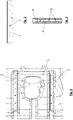
- Die Erfindung wird im Folgenden beispielhaft unter Bezugnahme auf die Zeichnungen beschrieben.
- Fig. 1
- ist eine schematische Ansicht von außen auf einen Ausschnitt eines durch ein erfindungsgemäßes Verfahren hergestellten Kunststofftanks.
- Fig. 2
- ist eine Ansicht eines Versteifungsprofils von der der Tankwand zugewandten Seite her.
- Fig. 3
- ist eine Ansicht eines Versteifungsprofils gemäß
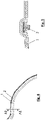
Fig. 2 von der der Tankwand abgewandten Seite her. - Fig. 4
- ist eine Ansicht auf einen Kunststofftank gemäß
Fig. 1 von der Seite und zeigt die Position des Schnittes A-A. - Fig. 5
- ist eine Schnittansicht des Schnittes A-A gemäß
Fig. 4 . - In
Fig. 1 ist ein Kunststofftank ausschnittsweise dargestellt, der auf erfindungsgemäße Weise hergestellt worden ist. - Der Kunststofftank umfasst eine Tankwand 1 aus Kunststoff, beispielsweise aus HDPE, und mindestens ein, im dargestellten Ausschnitt aber bereits zwei Versteifungsprofile 2, zur Minimierung einer unerwünschten Verformung des Kunststofftanks.
- Das Versteifungsprofil 2 wurde bei der Formung des Kunststofftanks in ein Schalenwerkzeug eingelegt, dann das Versteifungsprofil 2 mittels Unterdruck im Schalenwerkzeug in Position gehalten, sodann das Material der Tankwand 1 mittels Unterdruck an die Wände des Schalenwerkzeugs gesaugt um die Tankwand 1 auszuformen. Beim Ausformen der Tankwand 1 wurde dadurch das Material der Tankwand 1 um das Versteifungsprofil 2 gesaugt und dabei ein formschlüssiger Halt zwischen Tankwand 1 und Versteifungsprofil 2 hergestellt. Das Versteifungsprofil 2 weist einen T-förmigen Querschnitt auf und weist dadurch Hinterschneidungen auf, die vom Material der Tankwand 1 hintergriffen werden können. Ein stoffschlüssiger Halt zwischen Versteifungsprofil 2 und Tankwand 1 besteht nicht.
- Die Montage erfolgt also durch das formschlüssige Umschließen des Tankschalenmaterials im Fügeprozess. Die Versteifungsprofile 2 werden in das offene Schalenwerkzeug in eine dafür vorgesehene Kavität eingelegt und durch anlegen von Vakuum in Position gehalten. Die Tankwand 1 wird in einem weiteren Schritt durch Anlegen von Unterdruck um das Profil der Versteifungsprofile 2 gesaugt. Es wird so bereits während des Formvorganges die Verbindung zwischen Rippenelementen, also Versteifungsprofilen 2, und Tankblase, also Tankwand 1, erreicht. Die Montage erfolgt formschlüssig, wie beispielsweise in
Fig. 1, Fig. 3 undFig. 5 an der Form des Versteifungsprofils 2 gut ersichtlich. Möglich ist auch die Durchdringung des eingelegten Versteifungsprofils 2 durch das schmelzflüssige Schalenmaterial, also Material der Tankwand 1. Hierzu können im Versteifungsprofil 2 Öffnungen 3 ausgebildet sein, wie in denFig. 1 bis 3 dargestellt. Dies erzeugt durch zusätzliche Hinterschneidungen zusätzliche Festigkeit. - Eine zusätzliche Verpressung der Tankwand 1 zur Rippe bzw. dem Versteifungsprofil 2 kann durch den Schrumpf des Schalenmaterials von grob 3% im Abkühlprozess erreicht werden. Ein Schrumpf in Längsrichtung der Rippe 2 kann durch eine geeignete Aussparung oder Ausnehmung 4 zum Längenausgleich im Auslaufbereich der Rippen 2 vorgehalten werden.
- Die Versteifungsprofile bestehen aus einem Werkstoff mit hoher Festigkeit und hoher Biegesteifigkeit. Hierfür kommen insbesondere faserverstärkte Kunststoffe sowie Metallbauteile in Frage.
- Die Herstellung der Versteifungsprofile 2 kann wahlweise durch einen diskontinuierlichen Prozess wie Spritzguss oder einen kontinuierlichen Prozess wie Extrusion eines Profils ausgeführt werden.
- Ein Versteifungsprofil 2 kann durch einen Umformprozess in Form gebogen werden.
- Die geometrische Ausführung eines Versteifungsprofils 2 kann so ausgeführt werden, dass ein form- und kraftschlüssiger jedoch nicht stoffschlüssiger Verbund zwischen Tankwand 1 und Versteifungselement 2 eingegangen werden kann. Die Geometrie des Versteifungselements 2 ist der Tankgeometrie angepasst. Bevorzugte Geometrien sind Streben an der Tankschale.
- Ein Versteifungsprofil 2 kamm mehrere Öffnungen 3 aufweisen, so dass beim Ausformen der Tankwand 1 das Material der Tankwand 1 durch die Öffnungen 3 gesaugt wird und dabei ein verbesserter formschlüssiger Halt zwischen Tankwand 1 und Versteifungsprofil 2 entsteht.
-
- 1
- Tankwand
- 2
- Versteifungsprofil
- 3
- Öffnung
- 4
- Ausnehmung
Claims (7)
- Verfahren zur Herstellung eines Kunststofftanks, wobei der Kunststofftank eine Tankwand (1) aus Kunststoff und mindestens ein Versteifungsprofil (2) umfasst zur Minimierung einer unerwünschten Verformung des Kunststofftanks,
wobei das Versteifungsprofil (2) in ein Schalenwerkzeug eingelegt wird, dass das Versteifungsprofil (2) mittels Unterdruck im Schalenwerkzeug in Position gehalten wird, dadurch gekennzeichnet, dass das Material der Tankwand (1) mittels Unterdruck an die Wände des Schalenwerkzeugs gesaugt wird um die Tankwand (1) auszuformen, so dass beim Ausformen der Tankwand (1) das Material der Tankwand (1) um das Versteifungsprofil (2) gesaugt wird und dabei ein formschlüssiger Halt zwischen Tankwand (1) und Versteifungsprofil (2) entsteht, wobei das Versteifungsprofil (2) mehrere Öffnungen (3) aufweist, so dass beim Ausformen der Tankwand (1) das Material der Tankwand (1) durch die Öffnungen (3) gesaugt wird und dabei ein formschlüssiger Halt zwischen Tankwand (1) und Versteifungsprofil (2) entsteht. - Verfahren nach Anspruch 1,
dadurch gekennzeichnet, dass das Versteifungsprofil (2) aus faserverstärktem Kunststoff besteht. - Verfahren nach zumindest einem der vorhergehenden Ansprüche, dadurch gekennzeichnet, dass das Versteifungsprofil (2) in eine passende Ausnehmung im Schalenwerkzeug eingelegt wird und in der Ausnehmung mittels Unterdruck in Position gehalten wird.
- Verfahren nach zumindest einem der vorhergehenden Ansprüche, dadurch gekennzeichnet, dass das Versteifungsprofil (2) vor dem Einlegen in das Schalenwerkzeug durch einen kontinuierlichen Prozess wie Extrudieren hergestellt wird oder durch einen diskontinuierlichen Prozess wie Spritzgießen hergestellt wird.
- Verfahren nach zumindest einem der vorhergehenden Ansprüche, dadurch gekennzeichnet, dass das Versteifungsprofil (2) vor dem Einlegen in das Schalenwerkzeug in eine der späteren Tankwand (1) angepasste Form gebogen wird.
- Verfahren nach zumindest einem der vorhergehenden Ansprüche, dadurch gekennzeichnet, dass nach dem Ausformen der Tankwand (1) ein Abkühlprozess folgt, wobei beim Abkühlprozess das Material der Tankwand (1) so schrumpft, dass der formschlüssige Halt zwischen Tankwand (1) und Versteifungsprofil (2) verbessert wird.
- Verfahren nach zumindest einem der vorhergehenden Ansprüche, dadurch gekennzeichnet, dass das Versteifungsprofil (2) mindestens an einem Ende eine Ausnehmung (4) zum Längenausgleich aufweist.
Priority Applications (3)
| Application Number | Priority Date | Filing Date | Title |
|---|---|---|---|
| EP18211294.6A EP3666496B1 (de) | 2018-12-10 | 2018-12-10 | Verfahren zur herstellung eines kunststofftanks |
| US16/654,211 US20200180427A1 (en) | 2018-12-10 | 2019-10-16 | Method of manufacturing a plastic tank |
| CN201911058374.8A CN111284029A (zh) | 2018-12-10 | 2019-11-01 | 制造塑料罐的方法 |
Applications Claiming Priority (1)
| Application Number | Priority Date | Filing Date | Title |
|---|---|---|---|
| EP18211294.6A EP3666496B1 (de) | 2018-12-10 | 2018-12-10 | Verfahren zur herstellung eines kunststofftanks |
Publications (2)
| Publication Number | Publication Date |
|---|---|
| EP3666496A1 EP3666496A1 (de) | 2020-06-17 |
| EP3666496B1 true EP3666496B1 (de) | 2022-04-13 |
Family
ID=64664594
Family Applications (1)
| Application Number | Title | Priority Date | Filing Date |
|---|---|---|---|
| EP18211294.6A Active EP3666496B1 (de) | 2018-12-10 | 2018-12-10 | Verfahren zur herstellung eines kunststofftanks |
Country Status (3)
| Country | Link |
|---|---|
| US (1) | US20200180427A1 (de) |
| EP (1) | EP3666496B1 (de) |
| CN (1) | CN111284029A (de) |
Families Citing this family (2)
| Publication number | Priority date | Publication date | Assignee | Title |
|---|---|---|---|---|
| FR3089199B1 (fr) * | 2018-11-30 | 2022-05-13 | Plastic Omnium Advanced Innovation & Res | Renfort interne pour réservoir de véhicule automobile |
| EP3822062B1 (de) * | 2019-11-12 | 2021-10-20 | Magna Energy Storage Systems GesmbH | Kunststofftank und verfahren zur herstellung eines kunststofftanks |
Family Cites Families (8)
| Publication number | Priority date | Publication date | Assignee | Title |
|---|---|---|---|---|
| US5188981A (en) * | 1991-05-28 | 1993-02-23 | Ford Motor Company | Molded article with integral heat shield |
| DE202005014188U1 (de) * | 2005-09-08 | 2006-02-09 | Auer, Hans | Formeinlagefolien |
| DE102006002632A1 (de) * | 2006-01-19 | 2007-07-26 | Khs Ag | Verfahren zum Herstellen von Flaschen oder dergleichen Behältern aus Kunststoff durch Blasen sowie nach diesem Verfahren hergestellte Flaschen oder dergleichen Behälter |
| DE102010044584A1 (de) * | 2010-09-07 | 2012-03-08 | Kautex Textron Gmbh & Co. Kg | Kraftstoffbehälter aus thermoplastischem Kunststoff |
| EP2511068A1 (de) * | 2011-04-12 | 2012-10-17 | Inergy Automotive Systems Research (Société Anonyme) | Verfahren zur Herstellung eines Kunststoffkraftstofftanks |
| WO2014099534A1 (en) * | 2012-12-17 | 2014-06-26 | Ticona Llc | Blow molded composite component and method |
| JP6064949B2 (ja) * | 2014-07-15 | 2017-01-25 | トヨタ自動車株式会社 | 燃料タンクの製造方法及び燃料タンク |
| CN105135207B (zh) * | 2015-07-24 | 2018-02-02 | 石家庄安瑞科气体机械有限公司 | 一种储运高压气瓶中用的复合塑料内胆及其制备方法 |
-
2018
- 2018-12-10 EP EP18211294.6A patent/EP3666496B1/de active Active
-
2019
- 2019-10-16 US US16/654,211 patent/US20200180427A1/en not_active Abandoned
- 2019-11-01 CN CN201911058374.8A patent/CN111284029A/zh active Pending
Also Published As
| Publication number | Publication date |
|---|---|
| CN111284029A (zh) | 2020-06-16 |
| US20200180427A1 (en) | 2020-06-11 |
| EP3666496A1 (de) | 2020-06-17 |
Similar Documents
| Publication | Publication Date | Title |
|---|---|---|
| EP2465665B1 (de) | Verfahren zur Herstellung eines materialhybriden Bauteils | |
| DE3113791A1 (de) | "rohrfoermiger hohlkoerper, verfahren zu seiner herstellung sowie vorrichtung zur durchfuehrung des verfahrens" | |
| WO2011085792A1 (de) | Verfahren zur herstellung von endlosfaserverstärkten formteilen aus thermoplastischem kunststoff sowie kraftfahrzeugformteil | |
| EP3369544B1 (de) | Hohlprofil-verbundtechnologie | |
| DE102009056472A1 (de) | Verbundbauteil und Verfahren zu dessen Herstellung | |
| DE102005028766A1 (de) | Rohrleitung sowie Verfahren zur Herstellung der Rohrleitung | |
| EP3539744A1 (de) | Hohlprofil-verbundtechnologie | |
| DE102010015426A1 (de) | Verfahren zum Herstellen eines Verbundbauteils | |
| DE102024106614A1 (de) | Tank für ein unter Druck stehendes Fluid und zugehöriges Herstellungsverfahren | |
| DE102022105064A1 (de) | Verfahren zur Herstellung eines Faserverbundbauteils aus einem Faserverbundwerkstoff | |
| EP3666496A1 (de) | Verfahren zur herstellung eines kunststofftanks | |
| WO2016034321A1 (de) | Verfahren zum herstellen eines lokal verstärkten profilbauteils sowie mit diesem verfahren hergestelltes bauteil | |
| EP3668698B1 (de) | Verfahren zur herstellung eines bauteils aus einer als hohlkörper ausgebildeten preform | |
| DE102013222016A1 (de) | Verfahren zum Herstellen eines verstärkten Faserverbundbauteils in Schalenbauweise | |
| EP4436807A1 (de) | Koppelstange und verfahren zum herstellen | |
| EP2468473A1 (de) | Verfahren zur Herstellung eines Verbundbauteils und Verbundbauteil | |
| EP3601870B1 (de) | Druckbehälter sowie verfahren zur herstellung einer aussenhülle für einen druckbehälter | |
| EP3911490B1 (de) | Verfahren und vorrichtung zum herstellen einer fluidleitung mit verbindungselement | |
| EP3822062B1 (de) | Kunststofftank und verfahren zur herstellung eines kunststofftanks | |
| DE19713074C2 (de) | Verfahren zur Herstellung des Stützkörpers für eine Kopfstütze eines Kraftfahrzeugsitzes | |
| DE102013019470A1 (de) | Strukturbauteil mit einer Hohlstruktur | |
| DE102012018788A1 (de) | Verfahren zur Herstellung eines Verbundbauteils | |
| DE102017211419A1 (de) | Verfahren zur Herstellung eines faserverstärkten Bauteils für ein Kraftfahrzeug und faserverstärktes Bauteil | |
| WO2011069607A1 (de) | Verfahren zur herstellung eines faserverstärkten kunststoff - hohlprofils und das hergestellte profil | |
| EP3347193B1 (de) | Verfahren zum herstellen eines fmv-hybridbauteils und fmv-hybridbauteil |
Legal Events
| Date | Code | Title | Description |
|---|---|---|---|
| PUAI | Public reference made under article 153(3) epc to a published international application that has entered the european phase |
Free format text: ORIGINAL CODE: 0009012 |
|
| STAA | Information on the status of an ep patent application or granted ep patent |
Free format text: STATUS: THE APPLICATION HAS BEEN PUBLISHED |
|
| AK | Designated contracting states |
Kind code of ref document: A1 Designated state(s): AL AT BE BG CH CY CZ DE DK EE ES FI FR GB GR HR HU IE IS IT LI LT LU LV MC MK MT NL NO PL PT RO RS SE SI SK SM TR |
|
| AX | Request for extension of the european patent |
Extension state: BA ME |
|
| RAP1 | Party data changed (applicant data changed or rights of an application transferred) |
Owner name: MAGNA ENERGY STORAGE SYSTEMS GESMBH |
|
| STAA | Information on the status of an ep patent application or granted ep patent |
Free format text: STATUS: REQUEST FOR EXAMINATION WAS MADE |
|
| 17P | Request for examination filed |
Effective date: 20201111 |
|
| RBV | Designated contracting states (corrected) |
Designated state(s): AL AT BE BG CH CY CZ DE DK EE ES FI FR GB GR HR HU IE IS IT LI LT LU LV MC MK MT NL NO PL PT RO RS SE SI SK SM TR |
|
| GRAP | Despatch of communication of intention to grant a patent |
Free format text: ORIGINAL CODE: EPIDOSNIGR1 |
|
| STAA | Information on the status of an ep patent application or granted ep patent |
Free format text: STATUS: GRANT OF PATENT IS INTENDED |
|
| INTG | Intention to grant announced |
Effective date: 20220110 |
|
| GRAS | Grant fee paid |
Free format text: ORIGINAL CODE: EPIDOSNIGR3 |
|
| GRAA | (expected) grant |
Free format text: ORIGINAL CODE: 0009210 |
|
| STAA | Information on the status of an ep patent application or granted ep patent |
Free format text: STATUS: THE PATENT HAS BEEN GRANTED |
|
| AK | Designated contracting states |
Kind code of ref document: B1 Designated state(s): AL AT BE BG CH CY CZ DE DK EE ES FI FR GB GR HR HU IE IS IT LI LT LU LV MC MK MT NL NO PL PT RO RS SE SI SK SM TR |
|
| REG | Reference to a national code |
Ref country code: GB Ref legal event code: FG4D Free format text: NOT ENGLISH |
|
| REG | Reference to a national code |
Ref country code: CH Ref legal event code: EP |
|
| REG | Reference to a national code |
Ref country code: DE Ref legal event code: R096 Ref document number: 502018009383 Country of ref document: DE |
|
| REG | Reference to a national code |
Ref country code: IE Ref legal event code: FG4D Free format text: LANGUAGE OF EP DOCUMENT: GERMAN |
|
| REG | Reference to a national code |
Ref country code: AT Ref legal event code: REF Ref document number: 1483058 Country of ref document: AT Kind code of ref document: T Effective date: 20220515 |
|
| REG | Reference to a national code |
Ref country code: LT Ref legal event code: MG9D |
|
| REG | Reference to a national code |
Ref country code: NL Ref legal event code: MP Effective date: 20220413 |
|
| PG25 | Lapsed in a contracting state [announced via postgrant information from national office to epo] |
Ref country code: NL Free format text: LAPSE BECAUSE OF FAILURE TO SUBMIT A TRANSLATION OF THE DESCRIPTION OR TO PAY THE FEE WITHIN THE PRESCRIBED TIME-LIMIT Effective date: 20220413 |
|
| PG25 | Lapsed in a contracting state [announced via postgrant information from national office to epo] |
Ref country code: SE Free format text: LAPSE BECAUSE OF FAILURE TO SUBMIT A TRANSLATION OF THE DESCRIPTION OR TO PAY THE FEE WITHIN THE PRESCRIBED TIME-LIMIT Effective date: 20220413 Ref country code: PT Free format text: LAPSE BECAUSE OF FAILURE TO SUBMIT A TRANSLATION OF THE DESCRIPTION OR TO PAY THE FEE WITHIN THE PRESCRIBED TIME-LIMIT Effective date: 20220816 Ref country code: NO Free format text: LAPSE BECAUSE OF FAILURE TO SUBMIT A TRANSLATION OF THE DESCRIPTION OR TO PAY THE FEE WITHIN THE PRESCRIBED TIME-LIMIT Effective date: 20220713 Ref country code: LT Free format text: LAPSE BECAUSE OF FAILURE TO SUBMIT A TRANSLATION OF THE DESCRIPTION OR TO PAY THE FEE WITHIN THE PRESCRIBED TIME-LIMIT Effective date: 20220413 Ref country code: HR Free format text: LAPSE BECAUSE OF FAILURE TO SUBMIT A TRANSLATION OF THE DESCRIPTION OR TO PAY THE FEE WITHIN THE PRESCRIBED TIME-LIMIT Effective date: 20220413 Ref country code: GR Free format text: LAPSE BECAUSE OF FAILURE TO SUBMIT A TRANSLATION OF THE DESCRIPTION OR TO PAY THE FEE WITHIN THE PRESCRIBED TIME-LIMIT Effective date: 20220714 Ref country code: FI Free format text: LAPSE BECAUSE OF FAILURE TO SUBMIT A TRANSLATION OF THE DESCRIPTION OR TO PAY THE FEE WITHIN THE PRESCRIBED TIME-LIMIT Effective date: 20220413 Ref country code: ES Free format text: LAPSE BECAUSE OF FAILURE TO SUBMIT A TRANSLATION OF THE DESCRIPTION OR TO PAY THE FEE WITHIN THE PRESCRIBED TIME-LIMIT Effective date: 20220413 Ref country code: BG Free format text: LAPSE BECAUSE OF FAILURE TO SUBMIT A TRANSLATION OF THE DESCRIPTION OR TO PAY THE FEE WITHIN THE PRESCRIBED TIME-LIMIT Effective date: 20220713 |
|
| PG25 | Lapsed in a contracting state [announced via postgrant information from national office to epo] |
Ref country code: RS Free format text: LAPSE BECAUSE OF FAILURE TO SUBMIT A TRANSLATION OF THE DESCRIPTION OR TO PAY THE FEE WITHIN THE PRESCRIBED TIME-LIMIT Effective date: 20220413 Ref country code: PL Free format text: LAPSE BECAUSE OF FAILURE TO SUBMIT A TRANSLATION OF THE DESCRIPTION OR TO PAY THE FEE WITHIN THE PRESCRIBED TIME-LIMIT Effective date: 20220413 Ref country code: LV Free format text: LAPSE BECAUSE OF FAILURE TO SUBMIT A TRANSLATION OF THE DESCRIPTION OR TO PAY THE FEE WITHIN THE PRESCRIBED TIME-LIMIT Effective date: 20220413 Ref country code: IS Free format text: LAPSE BECAUSE OF FAILURE TO SUBMIT A TRANSLATION OF THE DESCRIPTION OR TO PAY THE FEE WITHIN THE PRESCRIBED TIME-LIMIT Effective date: 20220813 |
|
| REG | Reference to a national code |
Ref country code: DE Ref legal event code: R097 Ref document number: 502018009383 Country of ref document: DE |
|
| PG25 | Lapsed in a contracting state [announced via postgrant information from national office to epo] |
Ref country code: SM Free format text: LAPSE BECAUSE OF FAILURE TO SUBMIT A TRANSLATION OF THE DESCRIPTION OR TO PAY THE FEE WITHIN THE PRESCRIBED TIME-LIMIT Effective date: 20220413 Ref country code: SK Free format text: LAPSE BECAUSE OF FAILURE TO SUBMIT A TRANSLATION OF THE DESCRIPTION OR TO PAY THE FEE WITHIN THE PRESCRIBED TIME-LIMIT Effective date: 20220413 Ref country code: RO Free format text: LAPSE BECAUSE OF FAILURE TO SUBMIT A TRANSLATION OF THE DESCRIPTION OR TO PAY THE FEE WITHIN THE PRESCRIBED TIME-LIMIT Effective date: 20220413 Ref country code: EE Free format text: LAPSE BECAUSE OF FAILURE TO SUBMIT A TRANSLATION OF THE DESCRIPTION OR TO PAY THE FEE WITHIN THE PRESCRIBED TIME-LIMIT Effective date: 20220413 Ref country code: DK Free format text: LAPSE BECAUSE OF FAILURE TO SUBMIT A TRANSLATION OF THE DESCRIPTION OR TO PAY THE FEE WITHIN THE PRESCRIBED TIME-LIMIT Effective date: 20220413 Ref country code: CZ Free format text: LAPSE BECAUSE OF FAILURE TO SUBMIT A TRANSLATION OF THE DESCRIPTION OR TO PAY THE FEE WITHIN THE PRESCRIBED TIME-LIMIT Effective date: 20220413 |
|
| PLBE | No opposition filed within time limit |
Free format text: ORIGINAL CODE: 0009261 |
|
| STAA | Information on the status of an ep patent application or granted ep patent |
Free format text: STATUS: NO OPPOSITION FILED WITHIN TIME LIMIT |
|
| 26N | No opposition filed |
Effective date: 20230116 |
|
| PG25 | Lapsed in a contracting state [announced via postgrant information from national office to epo] |
Ref country code: AL Free format text: LAPSE BECAUSE OF FAILURE TO SUBMIT A TRANSLATION OF THE DESCRIPTION OR TO PAY THE FEE WITHIN THE PRESCRIBED TIME-LIMIT Effective date: 20220413 |
|
| PG25 | Lapsed in a contracting state [announced via postgrant information from national office to epo] |
Ref country code: SI Free format text: LAPSE BECAUSE OF FAILURE TO SUBMIT A TRANSLATION OF THE DESCRIPTION OR TO PAY THE FEE WITHIN THE PRESCRIBED TIME-LIMIT Effective date: 20220413 |
|
| REG | Reference to a national code |
Ref country code: CH Ref legal event code: PL |
|
| REG | Reference to a national code |
Ref country code: BE Ref legal event code: MM Effective date: 20221231 |
|
| PG25 | Lapsed in a contracting state [announced via postgrant information from national office to epo] |
Ref country code: LU Free format text: LAPSE BECAUSE OF NON-PAYMENT OF DUE FEES Effective date: 20221210 |
|
| PG25 | Lapsed in a contracting state [announced via postgrant information from national office to epo] |
Ref country code: LI Free format text: LAPSE BECAUSE OF NON-PAYMENT OF DUE FEES Effective date: 20221231 Ref country code: IE Free format text: LAPSE BECAUSE OF NON-PAYMENT OF DUE FEES Effective date: 20221210 Ref country code: CH Free format text: LAPSE BECAUSE OF NON-PAYMENT OF DUE FEES Effective date: 20221231 |
|
| PG25 | Lapsed in a contracting state [announced via postgrant information from national office to epo] |
Ref country code: BE Free format text: LAPSE BECAUSE OF NON-PAYMENT OF DUE FEES Effective date: 20221231 |
|
| PG25 | Lapsed in a contracting state [announced via postgrant information from national office to epo] |
Ref country code: IT Free format text: LAPSE BECAUSE OF FAILURE TO SUBMIT A TRANSLATION OF THE DESCRIPTION OR TO PAY THE FEE WITHIN THE PRESCRIBED TIME-LIMIT Effective date: 20220413 |
|
| PG25 | Lapsed in a contracting state [announced via postgrant information from national office to epo] |
Ref country code: HU Free format text: LAPSE BECAUSE OF FAILURE TO SUBMIT A TRANSLATION OF THE DESCRIPTION OR TO PAY THE FEE WITHIN THE PRESCRIBED TIME-LIMIT; INVALID AB INITIO Effective date: 20181210 |
|
| PG25 | Lapsed in a contracting state [announced via postgrant information from national office to epo] |
Ref country code: CY Free format text: LAPSE BECAUSE OF FAILURE TO SUBMIT A TRANSLATION OF THE DESCRIPTION OR TO PAY THE FEE WITHIN THE PRESCRIBED TIME-LIMIT Effective date: 20220413 |
|
| PG25 | Lapsed in a contracting state [announced via postgrant information from national office to epo] |
Ref country code: MK Free format text: LAPSE BECAUSE OF FAILURE TO SUBMIT A TRANSLATION OF THE DESCRIPTION OR TO PAY THE FEE WITHIN THE PRESCRIBED TIME-LIMIT Effective date: 20220413 |
|
| PG25 | Lapsed in a contracting state [announced via postgrant information from national office to epo] |
Ref country code: MC Free format text: LAPSE BECAUSE OF FAILURE TO SUBMIT A TRANSLATION OF THE DESCRIPTION OR TO PAY THE FEE WITHIN THE PRESCRIBED TIME-LIMIT Effective date: 20220413 |
|
| PG25 | Lapsed in a contracting state [announced via postgrant information from national office to epo] |
Ref country code: TR Free format text: LAPSE BECAUSE OF FAILURE TO SUBMIT A TRANSLATION OF THE DESCRIPTION OR TO PAY THE FEE WITHIN THE PRESCRIBED TIME-LIMIT Effective date: 20220413 Ref country code: MC Free format text: LAPSE BECAUSE OF FAILURE TO SUBMIT A TRANSLATION OF THE DESCRIPTION OR TO PAY THE FEE WITHIN THE PRESCRIBED TIME-LIMIT Effective date: 20220413 |
|
| PG25 | Lapsed in a contracting state [announced via postgrant information from national office to epo] |
Ref country code: MT Free format text: LAPSE BECAUSE OF FAILURE TO SUBMIT A TRANSLATION OF THE DESCRIPTION OR TO PAY THE FEE WITHIN THE PRESCRIBED TIME-LIMIT Effective date: 20220413 |
|
| PG25 | Lapsed in a contracting state [announced via postgrant information from national office to epo] |
Ref country code: BG Free format text: LAPSE BECAUSE OF FAILURE TO SUBMIT A TRANSLATION OF THE DESCRIPTION OR TO PAY THE FEE WITHIN THE PRESCRIBED TIME-LIMIT Effective date: 20220413 |
|
| PG25 | Lapsed in a contracting state [announced via postgrant information from national office to epo] |
Ref country code: BG Free format text: LAPSE BECAUSE OF FAILURE TO SUBMIT A TRANSLATION OF THE DESCRIPTION OR TO PAY THE FEE WITHIN THE PRESCRIBED TIME-LIMIT Effective date: 20220413 |
|
| REG | Reference to a national code |
Ref country code: AT Ref legal event code: MM01 Ref document number: 1483058 Country of ref document: AT Kind code of ref document: T Effective date: 20231210 |
|
| PG25 | Lapsed in a contracting state [announced via postgrant information from national office to epo] |
Ref country code: AT Free format text: LAPSE BECAUSE OF NON-PAYMENT OF DUE FEES Effective date: 20231210 |
|
| REG | Reference to a national code |
Ref country code: DE Ref legal event code: R082 Ref document number: 502018009383 Country of ref document: DE Representative=s name: EULER, MATTHIAS, DR., DE |
|
| PGFP | Annual fee paid to national office [announced via postgrant information from national office to epo] |
Ref country code: DE Payment date: 20251211 Year of fee payment: 8 |
|
| PGFP | Annual fee paid to national office [announced via postgrant information from national office to epo] |
Ref country code: GB Payment date: 20251219 Year of fee payment: 8 |
|
| PGFP | Annual fee paid to national office [announced via postgrant information from national office to epo] |
Ref country code: FR Payment date: 20251229 Year of fee payment: 8 |
|
| PGFP | Annual fee paid to national office [announced via postgrant information from national office to epo] |
Ref country code: AT Payment date: 20260410 Year of fee payment: 5 |