EP3666458A2 - Automatic process planning for robotic deburring operations - Google Patents
Automatic process planning for robotic deburring operations Download PDFInfo
- Publication number
- EP3666458A2 EP3666458A2 EP19215024.1A EP19215024A EP3666458A2 EP 3666458 A2 EP3666458 A2 EP 3666458A2 EP 19215024 A EP19215024 A EP 19215024A EP 3666458 A2 EP3666458 A2 EP 3666458A2
- Authority
- EP
- European Patent Office
- Prior art keywords
- burr
- deburring
- controller
- data
- tool
- Prior art date
- Legal status (The legal status is an assumption and is not a legal conclusion. Google has not performed a legal analysis and makes no representation as to the accuracy of the status listed.)
- Withdrawn
Links
Images


Classifications
-
- G—PHYSICS
- G05—CONTROLLING; REGULATING
- G05B—CONTROL OR REGULATING SYSTEMS IN GENERAL; FUNCTIONAL ELEMENTS OF SUCH SYSTEMS; MONITORING OR TESTING ARRANGEMENTS FOR SUCH SYSTEMS OR ELEMENTS
- G05B19/00—Program-control systems
- G05B19/02—Program-control systems electric
- G05B19/18—Numerical control [NC], i.e. automatically operating machines, in particular machine tools, e.g. in a manufacturing environment, so as to execute positioning, movement or co-ordinated operations by means of program data in numerical form
- G05B19/416—Numerical control [NC], i.e. automatically operating machines, in particular machine tools, e.g. in a manufacturing environment, so as to execute positioning, movement or co-ordinated operations by means of program data in numerical form characterised by control of velocity, acceleration or deceleration
- G05B19/4163—Adaptive control of feed or cutting velocity
-
- B—PERFORMING OPERATIONS; TRANSPORTING
- B25—HAND TOOLS; PORTABLE POWER-DRIVEN TOOLS; MANIPULATORS
- B25J—MANIPULATORS; CHAMBERS PROVIDED WITH MANIPULATION DEVICES
- B25J13/00—Controls for manipulators
- B25J13/08—Controls for manipulators by means of sensing devices, e.g. viewing or touching devices
- B25J13/085—Force or torque sensors
-
- B—PERFORMING OPERATIONS; TRANSPORTING
- B24—GRINDING; POLISHING
- B24B—MACHINES, DEVICES, OR PROCESSES FOR GRINDING OR POLISHING; DRESSING OR CONDITIONING OF ABRADING SURFACES; FEEDING OF GRINDING, POLISHING, OR LAPPING AGENTS
- B24B27/00—Other grinding machines or devices
- B24B27/003—Other grinding machines or devices using a tool turning around the work-piece
-
- B—PERFORMING OPERATIONS; TRANSPORTING
- B24—GRINDING; POLISHING
- B24B—MACHINES, DEVICES, OR PROCESSES FOR GRINDING OR POLISHING; DRESSING OR CONDITIONING OF ABRADING SURFACES; FEEDING OF GRINDING, POLISHING, OR LAPPING AGENTS
- B24B49/00—Measuring or gauging equipment for controlling the feed movement of the grinding tool or work; Arrangements of indicating or measuring equipment, e.g. for indicating the start of the grinding operation
- B24B49/16—Measuring or gauging equipment for controlling the feed movement of the grinding tool or work; Arrangements of indicating or measuring equipment, e.g. for indicating the start of the grinding operation taking regard of the load
-
- B—PERFORMING OPERATIONS; TRANSPORTING
- B24—GRINDING; POLISHING
- B24B—MACHINES, DEVICES, OR PROCESSES FOR GRINDING OR POLISHING; DRESSING OR CONDITIONING OF ABRADING SURFACES; FEEDING OF GRINDING, POLISHING, OR LAPPING AGENTS
- B24B51/00—Arrangements for automatic control of a series of individual steps in grinding a workpiece
-
- B—PERFORMING OPERATIONS; TRANSPORTING
- B24—GRINDING; POLISHING
- B24B—MACHINES, DEVICES, OR PROCESSES FOR GRINDING OR POLISHING; DRESSING OR CONDITIONING OF ABRADING SURFACES; FEEDING OF GRINDING, POLISHING, OR LAPPING AGENTS
- B24B9/00—Machines or devices designed for grinding edges or bevels on work or for removing burrs; Accessories therefor
-
- B—PERFORMING OPERATIONS; TRANSPORTING
- B25—HAND TOOLS; PORTABLE POWER-DRIVEN TOOLS; MANIPULATORS
- B25J—MANIPULATORS; CHAMBERS PROVIDED WITH MANIPULATION DEVICES
- B25J11/00—Manipulators not otherwise provided for
- B25J11/005—Manipulators for mechanical processing tasks
- B25J11/006—Deburring or trimming
-
- B—PERFORMING OPERATIONS; TRANSPORTING
- B25—HAND TOOLS; PORTABLE POWER-DRIVEN TOOLS; MANIPULATORS
- B25J—MANIPULATORS; CHAMBERS PROVIDED WITH MANIPULATION DEVICES
- B25J9/00—Program-controlled manipulators
- B25J9/16—Program controls
- B25J9/1628—Program controls characterised by the control loop
- B25J9/163—Program controls characterised by the control loop learning, adaptive, model based, rule based expert control
-
- G—PHYSICS
- G05—CONTROLLING; REGULATING
- G05B—CONTROL OR REGULATING SYSTEMS IN GENERAL; FUNCTIONAL ELEMENTS OF SUCH SYSTEMS; MONITORING OR TESTING ARRANGEMENTS FOR SUCH SYSTEMS OR ELEMENTS
- G05B2219/00—Program-control systems
- G05B2219/30—Nc systems
- G05B2219/36—Nc in input of data, input key till input tape
- G05B2219/36409—Geometric adaptation by sensing force on surface of workpiece, object
-
- G—PHYSICS
- G05—CONTROLLING; REGULATING
- G05B—CONTROL OR REGULATING SYSTEMS IN GENERAL; FUNCTIONAL ELEMENTS OF SUCH SYSTEMS; MONITORING OR TESTING ARRANGEMENTS FOR SUCH SYSTEMS OR ELEMENTS
- G05B2219/00—Program-control systems
- G05B2219/30—Nc systems
- G05B2219/36—Nc in input of data, input key till input tape
- G05B2219/36495—Recording position and other parameters, current, tool diameter, voltage
-
- G—PHYSICS
- G05—CONTROLLING; REGULATING
- G05B—CONTROL OR REGULATING SYSTEMS IN GENERAL; FUNCTIONAL ELEMENTS OF SUCH SYSTEMS; MONITORING OR TESTING ARRANGEMENTS FOR SUCH SYSTEMS OR ELEMENTS
- G05B2219/00—Program-control systems
- G05B2219/30—Nc systems
- G05B2219/45—Nc applications
- G05B2219/45151—Deburring
Definitions
- Controller 18 is configured to establish the trajectory of deburring tool 16 using CAM data 24 and deburring tool motion control module 60.
- CAM software is used to plan and control the machining and finishing processes for workpiece 28.
- the CAM software generates and stores CAM data 24 regarding the machining tool centerline trajectory and the machining tool location history during the machining and finishing operations for workpiece 28.
- Controller 18 uses the stored machining tool centerline trajectory and location history to establish the trajectory of deburring tool 16.
- CAM data 24 includes data that indicates the location of the perimeter of workpiece 28. Burrs 30 will be formed around the perimeter of workpiece 28. Therefore, deburring tool 16 needs to follow the perimeter of workpiece 28 to remove burrs 30 on workpiece 28.
- the predicted burr type is one of a Poisson burr, a roll-over burr, a tear burr, or a cut-off burr.
Landscapes
- Engineering & Computer Science (AREA)
- Mechanical Engineering (AREA)
- Robotics (AREA)
- Human Computer Interaction (AREA)
- Manufacturing & Machinery (AREA)
- Physics & Mathematics (AREA)
- General Physics & Mathematics (AREA)
- Automation & Control Theory (AREA)
- Manipulator (AREA)
- Processing And Handling Of Plastics And Other Materials For Molding In General (AREA)
- Finish Polishing, Edge Sharpening, And Grinding By Specific Grinding Devices (AREA)
Abstract
Description
- The present disclosure relates to a robotic deburring process and, in particular, to the use of data to automate the robotic deburring process.
- Burrs are small pieces of deformed material left on the edges of a workpiece during the finishing operation. Burr formation is a complicated process, which involves large plastic deformation of the workpiece material. The type of burr formed and its characteristics depend on many factors including, but not limited to, the machining process, tool properties, coolant properties, and workpiece material. In general, there are four basic types of burrs, the Poisson burr, roll-over burr, tear burr, and cut-off burr. Each type of burr requires a different deburring operation to effectively remove the burr.
- Robot systems have become common in industry due to their low cost, flexibility, and versatility. But only very few robots have been adopted in high-value added material removal applications, such as deburring and polishing. The main issues with the use of robots in high-value added applications include: lack of absolute accuracy of the robot, insufficient stiffness of robot arm during machining, and time-consuming, expert-dependent programming processes.
- In accordance with a first aspect, the present disclosure provides a deburring apparatus that includes a robot including a robot arm, a deburring tool attached to the robot arm, a plurality of force sensors attached to the robot arm, and a controller in data communication with the robot. The controller is configured to predict burr characteristics on a workpiece using manufacturing data, calculate joint positions of the robot arm using computer aided manufacturing (CAM) data, and establish the deburring tool trajectory using the CAM data. Further, the controller communicates the joint positions of the robot arm and the deburring tool trajectory to the robot and the controller directs the motion of the robot during the removal of a burr on the workpiece, based on the prediction of the burr characteristics.
- In accordance with a second aspect, the present disclosure provides a method for controlling a robotic deburring process, the method comprising predicting, by a controller, burr characteristics on a workpiece using manufacturing data. Calculating, by the controller, joint positions of a robot arm using computer aided manufacturing (CAM) data. Establishing, by the controller, a trajectory of a deburring tool connected to the robot arm using the CAM data. Communicating the joint positions of the robot arm and the trajectory of the deburring tool from the controller to a robot. Directing, by the controller, the motion of the robot during the removal of a burr on a workpiece, based on the predicted burr characteristics.
-
- FIG. 1
- is a schematic diagram of a robotic deburring apparatus.
- FIG. 2
- is an illustration of potential burr formations.
- FIG. 3
- is a block diagram of a controller used on the robotic deburring apparatus.
- FIG. 4
- is a flowchart of a method of operating the robotic deburring apparatus.
-
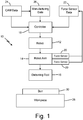
FIG. 1 is a schematic diagram ofrobotic deburring apparatus 10, which includesrobot 12,robot arm 14,deburring tool 16, andcontroller 18.Robot arm 14 includesforce sensors 20 attached torobot arm 14, which produceforce sensor data 22.Controller 18 receives, stores, and processes data, includingforce sensor data 22, computer aided manufacturing (CAM)data 24, andmanufacturing data 26.FIG. 1 further illustratesworkpiece 28 includingburr 30. -
Robot 12 is attached to and controlsrobot arm 14.Robot arm 14 is attached to and holdsdeburring tool 16.Robot arm 14 includesforce sensors 20, which are attached torobot arm 14 and generateforce sensor data 22 based on the movement ofrobot arm 14.Force sensors 20 can be positioned anywhere onrobot arm 14, but in oneembodiment force sensors 20 are positioned at the joints ofrobot arm 14.Deburring tool 16 is securely held byrobot arm 14.Controller 18 is connected to and controls the movement ofrobot 12 through a wired connection, wireless connection, or any other known means.Controller 18 receives, stores, and processesforce sensor data 22,CAM data 24, and manufacturingdata 26. -
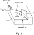
FIG. 2 is an illustration of potential burr formations, including deburringtool 16,workpiece 28, andburrs 30.Workpiece 28 can be any object that is being worked on by roboticdeburring apparatus 10. Burr 30 can be any type of burr that is generally known, butburr 30 will likely be one of a Poisson burr, a roll-over burr, a tear burr, or a cut-off burr.FIG. 2 illustrates a few types ofburr 30 formations onworkpiece 28, including a Poisson burr, a roll-over burr, and a tear burr. A Poisson burr is a burr that is formed when the machined material bulges outwards when the machining tool is applied to the workpiece under a downward pressure. A roll-over burr is typically produced when a cutting tool exits a material and the sharp tip of the tool pushes the material rather than cutting through or chipping it, thus creating the burr. A tear burr is created when material is torn away from a workpiece, rather than being sheared; this usually occurs during a punching or drilling process. A cut-off burr (not shown inFIG. 2 ) is produced when a portion of material falls away from the main workpiece, tearing it and leaving behind a burr. -
FIG. 3 is a block diagram ofcontroller 18 which includes processor(s) 50, communications device(s) 52, andmemory 54. In other embodiments,controller 18 can include more or fewer components thancomponents controller 18. For instance, processor(s) 50 can be capable of processing instructions stored inmemory 54. Examples of processor(s) 50 can include any one or more of a microprocessor, a controller, a digital signal processor (DSP), an application specific integrated circuit (ASIC), a field-programmable gate array (FPGA), or other equivalent discrete or integrated logic circuity.Memory 54 can include process instructions/modules such as, but not limited to, burrcharacteristic prediction module 56,joint position module 58, deburring toolmotion control module 60, andforce control module 62. -
Memory 54 can be configured to store information withincontroller 18 during operation.Memory 54, in some examples, is described as computer-readable storage media. In some examples, a computer-readable storage medium can include a non-transitory medium. The term "non-transitory" can indicate that the storage medium is not embodied in a carrier wave or a propagated signal. In certain examples, a non-transitory storage medium can store data that can, over time, change (e.g., in RAM or cache). In some examples,memory 54 is a temporary memory, meaning that a primary purpose ofmemory 54 is not long-term storage.Memory 54, in some examples, is described as volatile memory, meaning thatmemory 54 does not maintain stored contents when power to controller 18 is turned off. Examples of volatile memories can include random access memories (RAM), dynamic random access memories (DRAM), static random access memories (SRAM), and other forms of volatile memories. In some examples,memory 54 is used to store program instructions for execution by processor(s) 50.Memory 54, in one example, is used by software or applications running oncontroller 18 to temporarily store information during program execution. -
Memory 54, in some examples, also includes one or more computer-readable storage media.Memory 54 can be configured to store larger amounts of information than volatile memory.Memory 54 can further be configured for long-term storage of information. In some examples,memory 54 includes non-volatile storage elements. Examples of such non-volatile storage elements can include magnetic hard discs, optical discs, floppy discs, flash memories, or forms of electrically programmable memories (EPROM) or electrically erasable and programmable (EEPROM) memories. -
Controller 18, in some examples, also includes communications device(s) 52.Controller 18, in one example, utilizes communication device(s) 52 to communicate with external devices via one or more networks, such as one or more wireless or wired networks or both. Communications device(s) 52 can be a network interface card, such as an Ethernet card, an optical transceiver, a radio frequency transceiver, or any other type of device that can send and receive information. Other examples of such network interfaces can include Bluetooth, 3G, 4G, and WiFi radio computing devices as well as Universal Serial Bus (USB). -
FIG. 4 is a flowchart ofmethod 100 for operatingrobotic deburring apparatus 10. Step 102 includes predicting, by burrcharacteristic prediction module 56, burr characteristics onworkpiece 28 usingmanufacturing data 26. Step 104 includes calculating, byjoint position module 58, joint positions ofrobot arm 14 using computer aided manufacturing (CAM)data 24. Step 106 includes establishing, by deburring toolmotion control module 60, a trajectory of deburringtool 16 connected torobot arm 14 usingCAM data 24. Step 108 includes communicating the joint positions ofrobot arm 14 and the trajectory of deburringtool 16 by communication device(s) 52 fromcontroller 18 torobot 12. Step 110 includes directing, bycontroller 18, the motion ofrobot 12 during the removal ofburr 30 onworkpiece 28, based on the burr characteristics predicted by burrcharacteristic prediction module 56. - As mentioned above,
controller 18 has several functions, including but not limited to: predicting burr characteristics onworkpiece 28 usingmanufacturing data 26; calculating joint positions ofrobot arm 14 usingCAM data 24; establishing the trajectory of deburringtool 16 usingCAM data 24; compensating for insufficient stiffness ofrobot arm 14 using feedback provided byforce sensor data 22; communicating the joint positions ofrobot arm 14 torobot 12; communicating the trajectory of deburringtool 16 torobot 12; and directing the motion ofrobot 12 based on the predicted burr characteristics. -
Controller 18 is configured to predict burr characteristics onworkpiece 28 usingmanufacturing data 26 and burrcharacteristic prediction module 56.Controller 18 receivesmanufacturing data 26,processes manufacturing data 26 using burrcharacteristics prediction module 56, and outputs the predicted burr characteristics using communication device(s) 52. Specifically,controller 18processes manufacturing data 26 by extracting geometrical material removal and contact area data, calculating machining cutting conditions, calculating cutting forces and cutting temperatures, and estimating burr characteristics for all contacted edges. The predicted burr characteristics include the predicted burr size, predicted burr type, and predicted burr location. - The predicted burr characteristics depend on a variety of factors including, but not limited to, the material of
workpiece 28, the chip load during the machining and finishing ofworkpiece 28, and the properties of the coolant used during the machining and finishing ofworkpiece 28. Further, the predicted burr characteristics depend on the process parameters of the machining and finishing processes, the process parameters include: the machining tool cutting depth, machining tool cutting speed, machining tool feed rate, machining tool cutting force, machining tool material, machining tool geometry, and machining tool cutting temperature. The process parameters of the machining and finishing processes are gathered and recorded inmemory 54 during the machining and finishing operations ofworkpiece 28. Further,controller 18 uses burrcharacteristic prediction module 56 to predict the burr characteristics for a variety of machining operations, including milling operations, drilling operations, turning operations, and broaching operations. -
Controller 18 is configured to establish the trajectory of deburringtool 16 usingCAM data 24 and deburring toolmotion control module 60. CAM software is used to plan and control the machining and finishing processes forworkpiece 28. The CAM software generates andstores CAM data 24 regarding the machining tool centerline trajectory and the machining tool location history during the machining and finishing operations forworkpiece 28.Controller 18 uses the stored machining tool centerline trajectory and location history to establish the trajectory of deburringtool 16.CAM data 24 includes data that indicates the location of the perimeter ofworkpiece 28.Burrs 30 will be formed around the perimeter ofworkpiece 28. Therefore, deburringtool 16 needs to follow the perimeter ofworkpiece 28 to removeburrs 30 onworkpiece 28. Thus, deburringtool 16 will follow the same path/trajectory that was used during the machining and finishing operations forworkpiece 28 to removeburrs 30 on the perimeter ofworkpiece 28. In previous approaches to using robots to remove burrs, an expert was needed to program a machine to follow a perimeter of a workpiece to remove the burr. This was a time consuming, expert dependent, and complex process. Here,CAM data 24 used during the machining and finishing operations is reused to indicate the perimeter ofworkpiece 28 and deburring toolmotion control module 60 establishes the trajectory of deburringtool 16. -
Controller 18 is also configured to calculate the joint positions ofrobot arm 14 usingCAM data 24 andjoint position module 58. As discussed above, the CAM software generates andstores CAM data 24 regarding the machining tool centerline trajectory and the machining tool location history during the machining and finishing operations forworkpiece 28. Therefore,CAM data 24 includes data regarding the perimeter ofworkpiece 28 and the trajectory of deburringtool 16. With the trajectory of the deburring tool known,controller 18 is configured to calculate, usingjoint position module 58, the joint positions ofrobot arm 14 that allowdeburring tool 16 to reach every edge ofworkpiece 28.Joint position module 58 calculates the joint positions ofrobot arm 14 using reverse kinematics to determine the necessary movements ofrobot arm 14 that allowdeburring tool 16 to reach each and every edge ofworkpiece 28 without contacting anddamaging workpiece 28 in a location that was not intended to be contacted.Controller 18 calculates the joint positions ofrobot arm 14 to achieve a properly deburredworkpiece 28 without contactingworkpiece 28 in a damaging manner. -
Controller 18 is configured to usemanufacturing data 26 andCAM data 24 to determine the trajectory of deburringtool 16, speed ofdeburring tool 16, and feed rate of deburringtool 16. As discussed above,CAM data 24 is used to establish the trajectory of deburringtool 16. Further, as discussed above, manufacturingdata 26 is used to predict the burr characteristics for all edges ofworkpiece 28. Using the trajectory of deburringtool 16 and the predicted burr characteristics,controller 18 is able to optimize the deburring process parameters. Specifically,controller 18 uses deburring toolmotion control module 60 to establish the speed ofdeburring tool 16 and the feed rates of deburringtool 16 required to removeburr 30 fromworkpiece 28. The required speed ofdeburring tool 16 and the feed rate of deburringtool 16 depends on the size and type ofburr 30 onworkpiece 28. Each type ofburr 30 requires different deburring process parameters to removeburr 30 in an efficient manner. Therefore, the predicted burr characteristics allowscontroller 18 to determine the appropriate deburring process parameters required to removeburr 30. -
Controller 18 is configured to communicate torobot 12, using communication device(s) 52, the joint positions ofrobot arm 14, the trajectory of deburringtool 16, the speed ofdeburring tool 16, and the feed rates of deburringtool 16. After the information has been communicated fromcontroller 18 torobot 12,controller 18 directs the motion ofrobot 12 and the operation of deburringtool 16 during the deburring process.Robot 12 uses the joint positions ofrobot arm 14, the trajectory of deburringtool 16, the speed ofdeburring tool 16, and the feed rates of deburringtool 16 to controlrobot arm 14 and complete the deburring process. -
Controller 18 is further configured to compensate for insufficient stiffness ofrobot arm 14 usingforce sensor data 22 fromforce sensors 20 andforce control module 62. When the stiffness ofrobot arm 14 is insufficient,robot arm 14 will deflect when being pressed againstworkpiece 28, resulting in less force being applied toworkpiece 28 than intended. When this occurs, the force being applied toworkpiece 28 may be low enough thatburr 30 will not be removed. Therefore,force sensors 20 are attached torobot arm 14 and provide real-timeforce sensor data 22 regarding the movements and forces exerted byrobot arm 14.Force sensor data 22 is communicated torobot 12, which then communicatesforce sensor data 22 tocontroller 18.Controller 18 receives, stores, and processes forcesensor data 22 to determine if the proper amount of force is being applied toworkpiece 28 to removeburr 30. If the force being applied toworkpiece 28 is sufficient to removeburr 30,controller 18 will send a communication using, communication device(s) 52, torobot 12 indicatingrobot 12 should maintain the force being applied byrobot arm 14. If the force being applied toworkpiece 28 is insufficient to removeburr 30,controller 18 will send a communication, using communication device(s) 52, torobot 12 indicatingrobot 12 should increase the force being applied byrobot arm 14. Further, ifrobot arm 14 deflects when being pressed againstworkpiece 28,deburring tool 16 is likely not in its intended orientation/angle for removingburr 30 fromworkpiece 28.Force control module 62 further processes forcesensor data 22 fromforce sensors 20 to verify and adjust the orientation/angle of deburringtool 16 to achieve proper removal ofburr 30 fromworkpiece 28.Controller 18 usesforce sensor data 22 fromforce sensors 20 to verify the appropriate process parameters are being achieved during the deburring process. -
Robotic deburring apparatus 10 andmethod 100 for operatingrobotic deburring apparatus 10 result in an automatic deburring process that is no longer time consuming, expert dependent, and requires complex programming. Further,robotic deburring apparatus 10 andmethod 100 for operatingrobotic deburring apparatus 10 eliminate the need for complicated operator training for deburring programming and expert knowledge of deburring process planning.Robotic deburring apparatus 10 andmethod 100 ensure efficient removal ofburrs 30 fromworkpiece 28 while improving quality and reliability of the deburring process. - The following are non-exclusive descriptions of possible embodiments of the present invention.
- A deburring apparatus includes a robot including a robot arm, a deburring tool attached to the robot arm, a plurality of force sensors attached to the robot arm, and a controller in data communication with the robot. The controller is configured to predict burr characteristics on a workpiece using manufacturing data, calculate joint positions of the robot arm using computer aided manufacturing (CAM) data, and establish the deburring tool trajectory using the CAM data. Further, the controller communicates the joint positions of the robot arm and the deburring tool trajectory to the robot and the controller directs the motion of the robot during the removal of a burr on the workpiece, based on the prediction of the burr characteristics.
- The deburring apparatus of the preceding paragraph can optionally include, additionally and/or alternatively, any one or more of the following features, configurations and/or additional components:
The controller is further configured to use force sensor data from the force sensors to compensate for insufficient stiffness of the robot arm during a deburring process. - The controller compensates for insufficient stiffness of the robot arm by providing commands to the robot to adjust a force exerted by the robot arm and orientation or angle of the deburring tool during the deburring process.
- The CAM data includes a machining tool centerline trajectory or machining tool location history.
- The CAM data is data previously used to manufacture the workpiece.
- The predicted burr characteristics include predicted burr size, predicted burr type, and predicted burr location.
- The manufacturing data includes at least one of the workpiece material, chip load, coolant properties, machining tool cutting depth, machining tool cutting speed, machining tool feed rate, machining tool cutting force, machining tool material, machining tool geometry, and machining tool cutting temperature.
- The manufacturing data is gathered during a machining and a finishing operation of the workpiece.
- The controller directs the motion of the robot and operation of the deburring tool by using the manufacturing data and CAM data to determine the deburring tool trajectory, deburring tool speed, and deburring tool feed rate during a deburring process.
- The predicted burr type is one of a Poisson burr, a roll-over burr, a tear burr, or a cut-off burr.
- A method for controlling a robotic deburring process, the method comprising predicting, by a controller, burr characteristics on a workpiece using manufacturing data. Calculating, by the controller, joint positions of a robot arm using computer aided manufacturing (CAM) data. Establishing, by the controller, a trajectory of a deburring tool connected to the robot arm using the CAM data. Communicating the joint positions of the robot arm and the trajectory of the deburring tool from the controller to a robot. Directing, by the controller, the motion of the robot during the removal of a burr on a workpiece, based on the predicted burr characteristics.
- The method of the preceding paragraph can optionally include, additionally and/or alternatively, any one or more of the following features, configurations and/or additional components:
Utilizing force sensor data from a plurality of force sensors attached to the robot arm to compensate for insufficient stiffness of the robot arm. - Compensating for insufficient stiffness of the robot arm includes providing commands from the controller to the robot to adjust a force exerted by the robot arm and orientation or angle of the deburring tool during the deburring process.
- The CAM data includes a machining tool centerline trajectory or machining tool location history.
- The CAM data is data previously used to manufacture the workpiece.
- The predicted burr characteristics include predicted burr size, predicted burr type, and predicted burr location.
- The manufacturing data includes at least one of the workpiece material, chip load, coolant properties, machining tool cutting depth, machining tool cutting speed, machining tool feed rate, machining tool cutting force, machining tool material, machining tool geometry, and machining tool cutting temperature.
- The manufacturing data is gathered during a machining and a finishing operation of the workpiece.
- Directing, by the controller, the motion of the robot and operation of the deburring tool by using the manufacturing data and CAM data to determine the deburring tool trajectory, deburring tool speed, and deburring tool feed rate during a deburring process.
- The predicted burr type is one of a Poisson burr, a roll-over burr, a tear burr, or a cut-off burr.
- While the invention has been described with reference to an exemplary embodiments), it will be understood by those skilled in the art that various changes may be made and equivalents may be substituted for elements thereof without departing from the scope of the invention. In addition, many modifications may be made to adapt a particular situation or material to the teachings of the invention without departing from the essential scope thereof. Therefore, it is intended that the invention not be limited to the particular embodiments) disclosed, but that the invention will include all embodiments falling within the scope of the appended claims.
Claims (15)
- A deburring apparatus (10) comprising:a robot (12) including a robot arm (14);a deburring tool (16) attached to the robot arm (14);a plurality of force sensors (20) attached to the robot arm (14); anda controller (18) in data communication with the robot (12), the controller (18) being configured to:predict burr characteristics on a workpiece (28) using manufacturing data (26);calculate joint positions of the robot arm (14) using computer aided manufacturing (CAM) data (24); andestablish the deburring tool trajectory using the CAM data (24);wherein the controller (18) communicates the joint positions of the robot arm (14) and the deburring tool trajectory to the robot (12); andwherein the controller (18) directs the motion of the robot (12) during the removal of a burr (30) on the workpiece (28), based on the prediction of the burr characteristics.
- The deburring apparatus of claim 1, wherein the controller (18) is further configured to use force sensor data (22) from the force sensors (20) to compensate for insufficient stiffness of the robot arm (14) during a deburring process.
- The deburring apparatus of claim 2, wherein the controller (18) compensates for insufficient stiffness of the robot arm (14) by providing commands to the robot (12) to adjust a force exerted by the robot arm (14) and orientation or angle of the deburring tool (16) during the deburring process.
- The deburring apparatus of any preceding claim, wherein the CAM data (24) includes a machining tool centerline trajectory or machining tool location history, and wherein the CAM data (24) is data previously used to manufacture the workpiece (28).
- The deburring apparatus of any preceding claim, wherein the predicted burr characteristics include predicted burr size, predicted burr type, and predicted burr location.
- The deburring apparatus of claim 5, wherein the predicted burr type is one of a Poisson burr (30), a roll-over burr (30), a tear burr (30), or a cut-off burr.
- The deburring apparatus of any preceding claim, wherein:the manufacturing data (26) includes at least one of the workpiece material, chip load, coolant properties, machining tool cutting depth, machining tool cutting speed, machining tool feed rate, machining tool cutting force, machining tool material, machining tool geometry, and machining tool cutting temperature; andthe manufacturing data (26) is gathered during a machining and a finishing operation of the workpiece (28).
- The deburring apparatus of any preceding claim, wherein the controller (18) directs the motion of the robot (12) and operation of the deburring tool (16) by using the manufacturing data (26) and CAM data (24) to determine the deburring tool trajectory, deburring tool speed, and deburring tool feed rate during a deburring process.
- A method (100) for controlling a robotic deburring process, the method (100) comprising:predicting, by a controller (18), burr characteristics on a workpiece (28) using manufacturing data (26);calculating, by the controller (18), joint positions of a robot arm (14) using computer aided manufacturing (CAM) data;establishing, by the controller (18), a trajectory of a deburring tool (16) connected to the robot arm (14) using the CAM data (24);communicating the joint positions of the robot arm (14) and the trajectory of the deburring tool (16) from the controller (18) to a robot (12); anddirecting, by the controller (18), the motion of the robot (12) during the removal of a burr (30) on a workpiece (28), based on the predicting of the burr characteristics.
- The method of claim 9, further comprising utilizing force sensor data (22) from a plurality of force sensors (20) attached to the robot arm (14) to compensate for insufficient stiffness of the robot arm (14).
- The method of claim 10, wherein compensating for insufficient stiffness of the robot arm (14) includes providing commands from the controller (18) to the robot (12) to adjust a force exerted by the robot arm (14) and orientation or angle of the deburring tool (16) during the deburring process.
- The method of any of claims 9 to 11, wherein the CAM data (24) includes a machining tool centerline trajectory or machining tool location history, and wherein the CAM data (24) is data previously used to manufacture the workpiece (28).
- The method of any of claims 9 to 12, wherein:the predicted burr characteristics include predicted burr size, predicted burr type, and predicted burr location; andthe predicted burr type is one of a Poisson burr (30), a roll-over burr (30), a tear burr (30), or a cut-off burr.
- The method of any of claims 9 to 13, wherein:the manufacturing data (26) includes at least one of the workpiece material, chip load, coolant properties, machining tool cutting depth, machining tool cutting speed, machining tool feed rate, machining tool cutting force, machining tool material, machining tool geometry, and machining tool cutting temperature; andthe manufacturing data (26) is gathered during a machining and a finishing operation of the workpiece (28).
- The method of any of claims 9 to 14, further comprising directing, by the controller (18), the motion of the robot (12) and operation of the deburring tool (16) by using the manufacturing data (26) and CAM data (24) to determine the deburring tool trajectory, deburring tool speed, and deburring tool feed rate during a deburring process.
Applications Claiming Priority (1)
| Application Number | Priority Date | Filing Date | Title |
|---|---|---|---|
| US16/214,982 US10976728B2 (en) | 2018-12-10 | 2018-12-10 | Automatic process planning for robotic deburring operations |
Publications (2)
| Publication Number | Publication Date |
|---|---|
| EP3666458A2 true EP3666458A2 (en) | 2020-06-17 |
| EP3666458A3 EP3666458A3 (en) | 2020-07-08 |
Family
ID=68848162
Family Applications (1)
| Application Number | Title | Priority Date | Filing Date |
|---|---|---|---|
| EP19215024.1A Withdrawn EP3666458A3 (en) | 2018-12-10 | 2019-12-10 | Automatic process planning for robotic deburring operations |
Country Status (2)
| Country | Link |
|---|---|
| US (1) | US10976728B2 (en) |
| EP (1) | EP3666458A3 (en) |
Families Citing this family (2)
| Publication number | Priority date | Publication date | Assignee | Title |
|---|---|---|---|---|
| DE112021000635T5 (en) * | 2020-01-20 | 2022-12-08 | Fanuc Corporation | POLISH QUANTITY ESTIMATION DEVICE |
| CN119550147A (en) * | 2024-11-04 | 2025-03-04 | 北京天玛智控科技股份有限公司 | Robot deburring method, device and electronic equipment |
Citations (3)
| Publication number | Priority date | Publication date | Assignee | Title |
|---|---|---|---|---|
| US9186795B1 (en) * | 2013-06-24 | 2015-11-17 | Redwood Robotics, Inc. | Programming and execution of force-based tasks with torque-controlled robot arms |
| US9724801B2 (en) * | 2013-06-28 | 2017-08-08 | Fanuc Corporation | Deburring device including visual sensor and force sensor |
| JP2018083284A (en) * | 2016-11-11 | 2018-05-31 | セイコーエプソン株式会社 | Robot control apparatus, robot, robot system, and robot control method |
Family Cites Families (19)
| Publication number | Priority date | Publication date | Assignee | Title |
|---|---|---|---|---|
| US5761390A (en) * | 1991-12-12 | 1998-06-02 | Hitachi, Ltd. | Robot for removing unnecessary portion on workpiece |
| US5441437A (en) * | 1993-02-18 | 1995-08-15 | Hulstedt; Bryan A. | Compliant constant-force follower device for surface finishing tool |
| JPH06348318A (en) * | 1993-06-08 | 1994-12-22 | Fanuc Ltd | Method and device for controlling deburring robot |
| JP4098761B2 (en) * | 2004-08-17 | 2008-06-11 | ファナック株式会社 | Finishing method |
| EP1854037B1 (en) * | 2005-02-25 | 2014-12-31 | Abb Research Ltd. | Method of and apparatus for automated path learning |
| EP1987406B1 (en) * | 2006-02-23 | 2010-08-04 | Abb Ab | A system for controlling the position and orientation of an object in dependence on received forces and torques from a user |
| DE102006049957A1 (en) * | 2006-10-19 | 2008-04-24 | Abb Ag | System and method for calibration of a handling device |
| JP4267027B2 (en) * | 2006-12-07 | 2009-05-27 | ファナック株式会社 | Robot controller |
| US9605952B2 (en) * | 2012-03-08 | 2017-03-28 | Quality Manufacturing Inc. | Touch sensitive robotic gripper |
| US9186785B2 (en) | 2013-01-16 | 2015-11-17 | Cheng-Hao Hung | Bearing adjuster |
| EP2821872B1 (en) * | 2013-07-01 | 2017-02-08 | Getting Robotika S.L. | Robotised cell, installation and method for deburring parts |
| US10194890B2 (en) * | 2013-10-28 | 2019-02-05 | Brown University | Burr hole mounted stereotactic biopsy device |
| US9604357B2 (en) * | 2014-07-30 | 2017-03-28 | Kabushiki Kaisha Yaskawa Denki | Robot and device having multi-axis motion sensor, and method of use thereof |
| US10327849B2 (en) * | 2015-11-11 | 2019-06-25 | Mako Surgical Corp. | Robotic system and method for backdriving the same |
| CN111329552B (en) * | 2016-03-12 | 2021-06-22 | P·K·朗 | Augmented reality visualization for guided bone resection including robotics |
| US10058997B1 (en) * | 2016-06-16 | 2018-08-28 | X Development Llc | Space extrapolation for robot task performance |
| JP2018069361A (en) * | 2016-10-27 | 2018-05-10 | セイコーエプソン株式会社 | Force control coordinate axis setting device, robot, and force control coordinate axis setting method |
| JP6457468B2 (en) * | 2016-12-08 | 2019-01-23 | ファナック株式会社 | Deburring device |
| JP6577527B2 (en) * | 2017-06-15 | 2019-09-18 | ファナック株式会社 | Learning device, control device and control system |
-
2018
- 2018-12-10 US US16/214,982 patent/US10976728B2/en active Active
-
2019
- 2019-12-10 EP EP19215024.1A patent/EP3666458A3/en not_active Withdrawn
Patent Citations (3)
| Publication number | Priority date | Publication date | Assignee | Title |
|---|---|---|---|---|
| US9186795B1 (en) * | 2013-06-24 | 2015-11-17 | Redwood Robotics, Inc. | Programming and execution of force-based tasks with torque-controlled robot arms |
| US9724801B2 (en) * | 2013-06-28 | 2017-08-08 | Fanuc Corporation | Deburring device including visual sensor and force sensor |
| JP2018083284A (en) * | 2016-11-11 | 2018-05-31 | セイコーエプソン株式会社 | Robot control apparatus, robot, robot system, and robot control method |
Non-Patent Citations (2)
| Title |
|---|
| AURICH J C ET AL: "Burrs-Analysis, control and removal", CIRP ANNALS, ELSEVIER BV, NL, CH, FR, vol. 58, no. 2, 1 January 2009 (2009-01-01), pages 519 - 542, XP026770025, ISSN: 0007-8506, [retrieved on 20091014], DOI: 10.1016/J.CIRP.2009.09.004 * |
| POWELL MARK A: "AGILE EDGE FINISHING SYSTEM", FINISHING '95 CONFERENCE AND EXPOSITION, 18 September 1995 (1995-09-18), Cincinnati, Ohio, US, pages 621 - 638, XP055809680, Retrieved from the Internet <URL:https://p2infohouse.org/ref/25/24218.pdf> * |
Also Published As
| Publication number | Publication date |
|---|---|
| EP3666458A3 (en) | 2020-07-08 |
| US20200183363A1 (en) | 2020-06-11 |
| US10976728B2 (en) | 2021-04-13 |
Similar Documents
| Publication | Publication Date | Title |
|---|---|---|
| US20200290207A1 (en) | Real-time identification of burr size and location for robotic deburring process | |
| US20140123740A1 (en) | Working Abnormality Detecting Device and Working Abnormality Detecting Method for Machine Tool | |
| US20160184951A1 (en) | Cutting fluid supply system to machine tool | |
| CN101995848B (en) | Tool vector display apparatus for machine tool with rotational axes | |
| CN109079802B (en) | Correct the teaching apparatus of the robot of the track of robot | |
| CN104375456B (en) | Interference confirms device | |
| CN102467112B (en) | Machining method for machine tool | |
| US20010000805A1 (en) | Tool path data generation apparatus for NC machine tool and numerical controller provided with it | |
| KR20210062440A (en) | Manufacturing apparatus of machine tool using digital twin and the method thereof | |
| US20090198366A1 (en) | Method and device for operating a machine tool | |
| CN105446270B (en) | The control device of lathe | |
| US10088824B2 (en) | Toolpath evaluation method, toolpath generation method, and toolpath generation device | |
| US11567470B2 (en) | Computer-aided optimization of numerically controlled machining of a workpiece | |
| CN103460151A (en) | Method for machining workpieces by means of a numerically controlled workpiece machining device and workpiece machining device | |
| CN107850884B (en) | Trajectory determination method for non-productive time motion | |
| US10976728B2 (en) | Automatic process planning for robotic deburring operations | |
| JP6865059B2 (en) | Machine tool system, manufacturing method of machined products, machining program correction device, correction machining program creation method, and machine tool control device | |
| JP7586632B2 (en) | Control device and control method | |
| CN105094048A (en) | Numerical controller of laser beam machine | |
| US20170060116A1 (en) | Machining abnormality avoiding system and machining path modification method thereof | |
| CN105492980A (en) | Tool path generating method and tool path generating device | |
| US20180364681A1 (en) | Numerical controller | |
| CN110647109A (en) | Numerical controller | |
| CN110154043A (en) | The robot system and its control method of study control are carried out based on processing result | |
| EP1209544B1 (en) | Tool path data generation apparatus for nc machine tool and numerical controller provided with it |
Legal Events
| Date | Code | Title | Description |
|---|---|---|---|
| PUAI | Public reference made under article 153(3) epc to a published international application that has entered the european phase |
Free format text: ORIGINAL CODE: 0009012 |
|
| STAA | Information on the status of an ep patent application or granted ep patent |
Free format text: STATUS: THE APPLICATION HAS BEEN PUBLISHED |
|
| PUAL | Search report despatched |
Free format text: ORIGINAL CODE: 0009013 |
|
| AK | Designated contracting states |
Kind code of ref document: A2 Designated state(s): AL AT BE BG CH CY CZ DE DK EE ES FI FR GB GR HR HU IE IS IT LI LT LU LV MC MK MT NL NO PL PT RO RS SE SI SK SM TR |
|
| AX | Request for extension of the european patent |
Extension state: BA ME |
|
| AK | Designated contracting states |
Kind code of ref document: A3 Designated state(s): AL AT BE BG CH CY CZ DE DK EE ES FI FR GB GR HR HU IE IS IT LI LT LU LV MC MK MT NL NO PL PT RO RS SE SI SK SM TR |
|
| AX | Request for extension of the european patent |
Extension state: BA ME |
|
| RIC1 | Information provided on ipc code assigned before grant |
Ipc: B24B 9/00 20060101AFI20200604BHEP Ipc: B25J 11/00 20060101ALI20200604BHEP Ipc: B25J 9/16 20060101ALI20200604BHEP |
|
| STAA | Information on the status of an ep patent application or granted ep patent |
Free format text: STATUS: REQUEST FOR EXAMINATION WAS MADE |
|
| 17P | Request for examination filed |
Effective date: 20210108 |
|
| RBV | Designated contracting states (corrected) |
Designated state(s): AL AT BE BG CH CY CZ DE DK EE ES FI FR GB GR HR HU IE IS IT LI LT LU LV MC MK MT NL NO PL PT RO RS SE SI SK SM TR |
|
| RAP1 | Party data changed (applicant data changed or rights of an application transferred) |
Owner name: RAYTHEON TECHNOLOGIES CORPORATION |
|
| STAA | Information on the status of an ep patent application or granted ep patent |
Free format text: STATUS: EXAMINATION IS IN PROGRESS |
|
| 17Q | First examination report despatched |
Effective date: 20210623 |
|
| RAP3 | Party data changed (applicant data changed or rights of an application transferred) |
Owner name: RTX CORPORATION |
|
| STAA | Information on the status of an ep patent application or granted ep patent |
Free format text: STATUS: THE APPLICATION HAS BEEN WITHDRAWN |
|
| 18W | Application withdrawn |
Effective date: 20241106 |