EP3666383B1 - Electrical appliance with electrostatic dust collecting device using carbon fiber - Google Patents
Electrical appliance with electrostatic dust collecting device using carbon fiber Download PDFInfo
- Publication number
- EP3666383B1 EP3666383B1 EP19212984.9A EP19212984A EP3666383B1 EP 3666383 B1 EP3666383 B1 EP 3666383B1 EP 19212984 A EP19212984 A EP 19212984A EP 3666383 B1 EP3666383 B1 EP 3666383B1
- Authority
- EP
- European Patent Office
- Prior art keywords
- carbon fiber
- dust collecting
- charging device
- fiber electrodes
- circuit board
- Prior art date
- Legal status (The legal status is an assumption and is not a legal conclusion. Google has not performed a legal analysis and makes no representation as to the accuracy of the status listed.)
- Active
Links
Images













Classifications
-
- B—PERFORMING OPERATIONS; TRANSPORTING
- B03—SEPARATION OF SOLID MATERIALS USING LIQUIDS OR USING PNEUMATIC TABLES OR JIGS; MAGNETIC OR ELECTROSTATIC SEPARATION OF SOLID MATERIALS FROM SOLID MATERIALS OR FLUIDS; SEPARATION BY HIGH-VOLTAGE ELECTRIC FIELDS
- B03C—MAGNETIC OR ELECTROSTATIC SEPARATION OF SOLID MATERIALS FROM SOLID MATERIALS OR FLUIDS; SEPARATION BY HIGH-VOLTAGE ELECTRIC FIELDS
- B03C3/00—Separating dispersed particles from gases or vapour, e.g. air, by electrostatic effect
- B03C3/34—Constructional details or accessories or operation thereof
- B03C3/40—Electrode constructions
- B03C3/41—Ionising-electrodes
-
- B—PERFORMING OPERATIONS; TRANSPORTING
- B03—SEPARATION OF SOLID MATERIALS USING LIQUIDS OR USING PNEUMATIC TABLES OR JIGS; MAGNETIC OR ELECTROSTATIC SEPARATION OF SOLID MATERIALS FROM SOLID MATERIALS OR FLUIDS; SEPARATION BY HIGH-VOLTAGE ELECTRIC FIELDS
- B03C—MAGNETIC OR ELECTROSTATIC SEPARATION OF SOLID MATERIALS FROM SOLID MATERIALS OR FLUIDS; SEPARATION BY HIGH-VOLTAGE ELECTRIC FIELDS
- B03C3/00—Separating dispersed particles from gases or vapour, e.g. air, by electrostatic effect
- B03C3/02—Plant or installations having external electricity supply
- B03C3/04—Plant or installations having external electricity supply dry type
-
- B—PERFORMING OPERATIONS; TRANSPORTING
- B01—PHYSICAL OR CHEMICAL PROCESSES OR APPARATUS IN GENERAL
- B01D—SEPARATION
- B01D46/00—Filters or filtering processes specially modified for separating dispersed particles from gases or vapours
- B01D46/66—Regeneration of the filtering material or filter elements inside the filter
- B01D46/785—Regeneration of the filtering material or filter elements inside the filter by electrical means, e.g. for the generation of electrostatic forces in order to reject particles
-
- B—PERFORMING OPERATIONS; TRANSPORTING
- B03—SEPARATION OF SOLID MATERIALS USING LIQUIDS OR USING PNEUMATIC TABLES OR JIGS; MAGNETIC OR ELECTROSTATIC SEPARATION OF SOLID MATERIALS FROM SOLID MATERIALS OR FLUIDS; SEPARATION BY HIGH-VOLTAGE ELECTRIC FIELDS
- B03C—MAGNETIC OR ELECTROSTATIC SEPARATION OF SOLID MATERIALS FROM SOLID MATERIALS OR FLUIDS; SEPARATION BY HIGH-VOLTAGE ELECTRIC FIELDS
- B03C3/00—Separating dispersed particles from gases or vapour, e.g. air, by electrostatic effect
- B03C3/02—Plant or installations having external electricity supply
- B03C3/04—Plant or installations having external electricity supply dry type
- B03C3/12—Plant or installations having external electricity supply dry type characterised by separation of ionising and collecting stations
-
- B—PERFORMING OPERATIONS; TRANSPORTING
- B03—SEPARATION OF SOLID MATERIALS USING LIQUIDS OR USING PNEUMATIC TABLES OR JIGS; MAGNETIC OR ELECTROSTATIC SEPARATION OF SOLID MATERIALS FROM SOLID MATERIALS OR FLUIDS; SEPARATION BY HIGH-VOLTAGE ELECTRIC FIELDS
- B03C—MAGNETIC OR ELECTROSTATIC SEPARATION OF SOLID MATERIALS FROM SOLID MATERIALS OR FLUIDS; SEPARATION BY HIGH-VOLTAGE ELECTRIC FIELDS
- B03C3/00—Separating dispersed particles from gases or vapour, e.g. air, by electrostatic effect
- B03C3/34—Constructional details or accessories or operation thereof
-
- B—PERFORMING OPERATIONS; TRANSPORTING
- B03—SEPARATION OF SOLID MATERIALS USING LIQUIDS OR USING PNEUMATIC TABLES OR JIGS; MAGNETIC OR ELECTROSTATIC SEPARATION OF SOLID MATERIALS FROM SOLID MATERIALS OR FLUIDS; SEPARATION BY HIGH-VOLTAGE ELECTRIC FIELDS
- B03C—MAGNETIC OR ELECTROSTATIC SEPARATION OF SOLID MATERIALS FROM SOLID MATERIALS OR FLUIDS; SEPARATION BY HIGH-VOLTAGE ELECTRIC FIELDS
- B03C3/00—Separating dispersed particles from gases or vapour, e.g. air, by electrostatic effect
- B03C3/34—Constructional details or accessories or operation thereof
- B03C3/38—Particle charging or ionising stations, e.g. using electric discharge, radioactive radiation or flames
-
- B—PERFORMING OPERATIONS; TRANSPORTING
- B03—SEPARATION OF SOLID MATERIALS USING LIQUIDS OR USING PNEUMATIC TABLES OR JIGS; MAGNETIC OR ELECTROSTATIC SEPARATION OF SOLID MATERIALS FROM SOLID MATERIALS OR FLUIDS; SEPARATION BY HIGH-VOLTAGE ELECTRIC FIELDS
- B03C—MAGNETIC OR ELECTROSTATIC SEPARATION OF SOLID MATERIALS FROM SOLID MATERIALS OR FLUIDS; SEPARATION BY HIGH-VOLTAGE ELECTRIC FIELDS
- B03C3/00—Separating dispersed particles from gases or vapour, e.g. air, by electrostatic effect
- B03C3/34—Constructional details or accessories or operation thereof
- B03C3/66—Applications of electricity supply techniques
-
- F—MECHANICAL ENGINEERING; LIGHTING; HEATING; WEAPONS; BLASTING
- F24—HEATING; RANGES; VENTILATING
- F24F—AIR-CONDITIONING; AIR-HUMIDIFICATION; VENTILATION; USE OF AIR CURRENTS FOR SCREENING
- F24F1/00—Room units for air-conditioning, e.g. separate or self-contained units or units receiving primary air from a central station
- F24F1/0007—Indoor units, e.g. fan coil units
- F24F1/0071—Indoor units, e.g. fan coil units with means for purifying supplied air
-
- F—MECHANICAL ENGINEERING; LIGHTING; HEATING; WEAPONS; BLASTING
- F24—HEATING; RANGES; VENTILATING
- F24F—AIR-CONDITIONING; AIR-HUMIDIFICATION; VENTILATION; USE OF AIR CURRENTS FOR SCREENING
- F24F8/00—Treatment, e.g. purification, of air supplied to human living or working spaces otherwise than by heating, cooling, humidifying or drying
- F24F8/10—Treatment, e.g. purification, of air supplied to human living or working spaces otherwise than by heating, cooling, humidifying or drying by separation, e.g. by filtering
-
- F—MECHANICAL ENGINEERING; LIGHTING; HEATING; WEAPONS; BLASTING
- F24—HEATING; RANGES; VENTILATING
- F24F—AIR-CONDITIONING; AIR-HUMIDIFICATION; VENTILATION; USE OF AIR CURRENTS FOR SCREENING
- F24F8/00—Treatment, e.g. purification, of air supplied to human living or working spaces otherwise than by heating, cooling, humidifying or drying
- F24F8/10—Treatment, e.g. purification, of air supplied to human living or working spaces otherwise than by heating, cooling, humidifying or drying by separation, e.g. by filtering
- F24F8/192—Treatment, e.g. purification, of air supplied to human living or working spaces otherwise than by heating, cooling, humidifying or drying by separation, e.g. by filtering by electrical means, e.g. by applying electrostatic fields or high voltages
- F24F8/194—Treatment, e.g. purification, of air supplied to human living or working spaces otherwise than by heating, cooling, humidifying or drying by separation, e.g. by filtering by electrical means, e.g. by applying electrostatic fields or high voltages by filtering using high voltage
Definitions
- the charging device may be fixed to a charging device holder provided in the main body, and the plurality of electron blocking plates may be provided in the charging device holder at regular intervals.
- the plurality of electron blocking plates may be provided on a lower surface of the housing.
- the plurality of carbon fiber electrodes may be disposed in parallel to the printed circuit board, and the ground electrode may be disposed on the printed circuit board and positioned on an opposite side of the plurality of carbon fibers based on the electrode bars of the plurality of carbon fiber electrodes.
- the charging device 1, the dust collecting device 120, and the air moving device 130 as described above may constitute an electrostatic dust collecting device using carbon fibers according to an embodiment of the present disclosure.
- the processing part 140 may not be included inside the main body 110.
- FIG. 3 is a perspective view illustrating a charging device of an electrostatic dust collecting device using carbon fibers according to an embodiment of the present disclosure.
- FIG. 4 is an exploded perspective view illustrating the charging device of FIG. 3
- FIG. 5 is a cross-sectional view illustrating the charging device of FIG. 3 .
- FIG. 6 is a rear perspective view illustrating the charging device of FIG. 3 .
- FIG. 7 is a perspective view illustrating a printed circuit board of the charging device of FIG. 3 on which a plurality of carbon fiber electrodes are disposed.
- the housing 10 is formed to accommodate the plurality of carbon fiber electrodes 20 and the printed circuit board 30.
- An opening 11 is formed on one surface of the housing 10 facing the tips of the plurality of carbon fiber electrodes 20, that is, on the front surface of the housing 10.
- a rear opening 13 may be provided on the opposite side of the one surface of the housing 10, that is, on the rear surface of the housing 10.
- the plurality of carbon fiber electrodes 20 may be exposed through the opening 11 of the housing 10. Therefore, the housing 10 is formed so that the outside air can flow through the inside of the housing 10.
- the plurality of carbon fiber electrodes 20 are configured to generate electrons at the tip of each of the carbon fiber electrodes 20 when a high voltage is applied thereto.
- the plurality of carbon fiber electrodes 20 are disposed such that the tips of the carbon fiber electrodes 20 face the opening 11 of the housing 10. Therefore, the electrons generated from the plurality of carbon fiber electrodes 20 are emitted to the outside through the opening 11 of the housing 10.
- the charging device 1 is disposed in the electrical appliance 100 such that the opening 11 of the housing 10 faces the inlet 111 of the main body 110 as illustrated in FIG. 2
- the tips of the plurality of carbon fiber electrodes 20 are arranged to face the inlet 111. Accordingly, because electrons generated from the plurality of carbon fiber electrodes 20 are emitted to the outside through the opening 11 of the housing 10, the contaminants contained in the air sucked into the inlet 111 may be charged.
- the printed circuit board 30 is provided with a power supply line 31 capable of applying power to the plurality of carbon fiber electrodes 20.
- a high voltage applying part 60 is connected to the power supply line 31 of the printed circuit board 30. Therefore, a high voltage may be applied to the plurality of carbon fiber electrodes 20 through the power supply line 31 of the printed circuit board 30.
- the high voltage applying part 60 may be configured to apply a voltage of about 6 kV to the plurality of carbon fiber electrodes 20 through the power supply line 31 of the printed circuit board 30.
- the printed circuit board 30 is supported by a plurality of supporting portions 16 provided inside the housing 10.
- the plurality of supporting portions 16 may be provided on the inner surfaces of the upper surface and the lower surface of the housing 10 so as to support the printed circuit board 30.
- a center supporting portion 17 may be provided on the inner surface of each of both ends of the housing 10 to support the both ends of the printed circuit board 30.
- the plurality of carbon fiber electrodes 20 may include an appropriate number of carbon fiber electrodes 20 to emit electrons to all the air sucked into the inlet 111 of the main body 110.
- six carbon fiber electrodes 20 are provided on the printed circuit board 30, but this is merely an example.
- the number of the plurality of carbon fiber electrodes 20 and the distance between the two adjacent carbon fiber electrodes 20 may be appropriately determined depending on the size of the inlet 111 of the main body 110 in which the charging device 1 is disposed.
- the printed circuit board 30 is formed to have a length capable of supporting the plurality of carbon fiber electrodes 20 arranged in a single line.
- the printed circuit board 30 on which the plurality of carbon fiber electrodes 20 are disposed may be formed to have a length equal to or greater than 1/3 of the length of the inlet 111 of the main body 110.
- the electrode bar 21 may be formed in a substantially cylindrical shape so as to support the plurality of carbon fibers 22 and be fixed to the printed circuit board 30. In other words, one end of the electrode bar 21 is fixed to the printed circuit board 30, and the plurality of carbon fibers 22 are provided at the other end of the electrode bar 21. Further, the electrode bar 21 is electrically connected to the power supply line 31 of the printed circuit board 30.
- the electrode bar 21 may be formed of a conductive material to apply power to the plurality of carbon fibers 22.
- the ground electrode 40 maintains a predetermined potential difference between each of the plurality of carbon fiber electrodes 20 and the surrounding air so that a predetermined amount of electrons is generated from the plurality of carbon fiber electrodes 20 even after a lapse of time.
- the ground electrode 40 is disposed around the plurality of carbon fiber electrodes 20.
- the ground electrode 40 may be disposed in the vicinity of the printed circuit board 30 so as not to face the tips of the plurality of carbon fiber electrodes 20.
- the ground electrode 40 may be disposed behind the printed circuit board 30 on the opposite side of one side surface of the printed circuit board 30 on which the plurality of carbon fiber electrodes 20 are provided or the plurality of carbon fiber electrodes 20.
- the ground electrode 40 may be disposed on the rear surface of the housing 10.
- an electrode fixing portion 18 to which the ground electrode 40 is fixed may be provided on the rear surface of the housing 10.
- the ground electrode 40 may be disposed on the rear surface of the housing 10 spaced apart by a predetermined distance from the opposite surface of the printed circuit board 30 opposite to the plurality of carbon fiber electrodes 20 provided on one surface of the printed circuit board 30.
- the rear opening 13 of the housing 10 may be provided on the rear surface of the housing 10 on both sides of the ground electrode 40.
- the ground electrode 40 may include a plurality of through holes 41.
- a plurality of fixing pins 18a corresponding to the plurality of through holes 41 of the ground electrode 40 are provided in the electrode fixing portion 18 of the housing 10. Therefore, when the plurality of fixing pins 18a of the housing 10 are inserted into the plurality of through holes 41 of the ground electrode 40, the ground electrode 40 is fixed to the electrode fixing portion 18 of the housing 10.
- FIG. 8 is a graph comparing an electron generation amount of a charging device according to an embodiment of the present disclosure having a ground electrode with an electron generation amount of a conventional charging device without a ground electrode.
- the plurality of carbon fiber electrodes 20 are exposed to the outside, when a user cleans the electrical appliance 100 equipped with the electrostatic dust collecting device using carbon fibers according to an embodiment of the present disclosure, a hand or a part of the body of the user may contact the plurality of carbon fiber electrodes 20. At this time, because a high voltage is applied to the plurality of carbon fiber electrodes 20, the user may be subjected to electric shock when the hand or a part of the body touches the carbon fiber electrodes 20.
- FIG. 10 is a cross-sectional view illustrating an example of a charging device of an electrostatic dust collecting device using carbon fibers according to an embodiment of the present disclosure.
- a plurality of carbon fiber electrodes 20, a printed circuit board 30, and a ground electrode 40 of the charging device 1' of FIG. 10 are the same as those of the charging device 1 according to the above-described embodiment except for the shape of the housing 10' and the protection grille 50'. Therefore, detailed descriptions thereof is omitted.
- the housing 10' is formed in a substantially hollow rectangular parallelepiped shape having a long length and an opening 11 through which the plurality of carbon fiber electrodes 20 are exposed is provided on the front surface of the housing 10'.
- the front end of the housing 10' is formed higher than the tips of the plurality of carbon fiber electrodes 20. Therefore, in FIG. 10 , the tips of the plurality of carbon fiber electrodes 20 are positioned behind the opening 11 of the housing 10'.
- an electrode fixing portion 18 on which the ground electrode 40 is disposed is provided on the rear surface of the housing 10' and a rear opening 13 is provided on both sides of the electrode fixing portion 18.
- the protection grille 50 is formed in a substantially hollow rectangular parallelepiped shape having a long length.
- the front surface of the protection grille 50 is provided with a pattern portion 51 that blocks the user's hand or finger and through which air can pass.
- the rear end of the protection grille 50 may be connected to the opening 11 of the housing 10".
- the pattern portion 51 of the protection grille 50 is spaced apart by a predetermined distance from the tips of the plurality of carbon fiber electrodes 20. In other words, there is a certain gap between the inner surface of the front surface of the protection grille 50 and the tips of the plurality of carbon fiber electrodes 20.
- the pattern portion 51 of the protection grille 50 may be formed in various patterns having holes 53 that block the user's hand or finger and through which the air can pass as illustrated in FIGS. 9A to 9G .
- FIG. 12 is a cross-sectional view illustrating an example of a charging device of an electrostatic dust collecting device using carbon fibers according to an embodiment of the present disclosure.
- the charging device 2' illustrated in FIG. 12 is the same as the charging device 2 illustrated in FIG. 11 described above, except that the ground electrode 40' is provided on the inner surface of the lower surface 10b of the housing 10"; therefore, the detailed description thereof is omitted.
- the housing 310 is formed in a substantially hollow rectangular parallelepiped shape having a long length and an opening 311 through which the plurality of carbon fiber electrodes 320 are exposed is provided on the front surface of the housing 310.
- the front end of the housing 310 is formed to be higher than the tips of the plurality of carbon fiber electrodes 320. Therefore, in FIG. 13 , the tips 320a of the plurality of carbon fiber electrodes 320 are positioned behind the opening 311 of the housing 310.
- the rear surface of the housing 310 is provided with a rear opening 313 through which air is passed.
- the plurality of carbon fiber electrodes 320 are disposed on the printed circuit board 330 such that the tips 320a thereof face the opening 311 of the housing 310.
- the plurality of carbon fiber electrodes 320 are disposed on the printed circuit board 330 to form a straight line at regular intervals. Further, the plurality of carbon fiber electrodes 320 are provided on the printed circuit board 330 such that the tips 320a thereof are positioned on the same plane.
- the plurality of carbon fiber electrodes 320 are disposed on the printed circuit board 330 so as to face the opening 311 of the housing 310, and the ground electrode 340 is disposed on the printed circuit board 330 so as to be adjacent to the rear opening 313 of the housing 310.
- FIG. 14 is a perspective view illustrating an indoor part of an air conditioner having an electrostatic dust collecting device using carbon fibers according to an embodiment of the present disclosure
- FIG. 15 is a cross-sectional view illustrating the indoor part of the air conditioner of FIG. 14 .
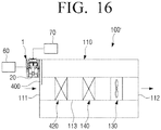
- FIG. 16 is a conceptual view illustrating an electrical appliance including an electrostatic dust collecting device using carbon fibers according to an embodiment of the present disclosure.
- a plurality of fixing protrusions for fixing the printed circuit board 30 to the housing 10 may be provided at a rear end of the protection grille 50.
- the protection grille 50 is coupled to the opening 11 of the housing 10, the pattern portion 51 of the protection grille 50 is spaced apart by a predetermined distance from the tips of the plurality of carbon fiber electrodes 20 and the printed circuit board 30 is fixed to the inside of the housing 10. Therefore, there is a certain gap between the inner surface of the front surface of the protection grille 50 and the tips of the plurality of carbon fiber electrodes 20 fixed to the housing 10.
- the plurality of electron blocking plates 400 may be formed to be spaced apart at regular intervals in the longitudinal direction of the charging device holder 401.
- the plurality of electron blocking plates 400 may be formed to correspond one-to-one with the plurality of carbon fiber electrodes 20 of the charging device 1. For example, as illustrated in FIG. 19 , when the charging device 1 includes six carbon fiber electrodes 20, six electron blocking plates 400 are also provided.
- the plurality of electron blocking plates 400 may be injection molded integrally with the charging device holder 401 when the charging device holder 401 is injection molded using plastic.
- the plurality of electron blocking plates 400 may be formed in the protection grille 450.
- the plurality of electron blocking plates 400 may be formed to protrude forward from the lower end of the protection grille 450.
- the plurality of electron blocking plates 400 may be formed at substantially right angles with respect to the protection grille 450.
- the plurality of electron blocking plates 400 may be formed to be spaced apart at regular intervals in the longitudinal direction of the protection grille 450.
- the plurality of electron blocking plates 400 may be formed to correspond one-to-one with the plurality of carbon fiber electrodes 20 provided under the protection grille 450.
- the plurality of electron blocking plates 400 may be injection molded integrally with the protection grille 450 when the protection grille 450 is injection molded using plastic.
- FIG. 21 is an exploded perspective view illustrating a charging device in which a plurality of electron blocking plates are provided in a housing of the charging device.
- the electron blocking plates 400 may affect the amount of air introduced into the inlet 111.
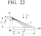
- the size of the electron blocking plate 400 may be determined such that the number of electrons directly attached to the dust collecting plates 421 among the electrons emitted from the carbon fiber electrodes 20 can be minimized while minimizing the reduction of the amount of air introduced therein.
- the width W of the portion of the electron blocking plate 400 protruding from the front surface of the protection grille 50 is larger than the protruding length L thereof, the reduction of the amount of air may be minimized and the number of electrons directly attached to the dust collecting plates 421 among the electrons emitted from the carbon fiber electrodes 20 may be minimized.
- the width W of the electron blocking plate 400 may be 16 mm, and the protruding length L thereof may be 10 mm.
- the width W of the electron blocking plate 400 is made too large, the amount of air flowing into the inlet 111 decreases, thereby reducing the clean area that can be collected by the dust collecting device 420.
- some of electrons generated in the carbon fiber electrodes 20 may be blocked by the electron blocking plates 400 and may not be directly introduced into the dust collecting device 420. Some of electrons that are not blocked by the electron blocking plates 400 may be directly introduced into the dust collecting device 420.
- the distance D between the carbon fiber electrodes 20 and the electron blocking plates 400 needs to be smaller than 1/2 of the distance C between the carbon fiber electrode 20 and the top surface of the dust collecting device 420 (that is, D ⁇ 1/2C).
- some of electrons generated in the carbon fiber electrodes 20 may be blocked by the electron blocking plates 400 and may not be directly attached to the dust collecting device 420. Some of electrons that are not blocked by the electron blocking plates 400 may be directly introduced into the dust collecting device 420.
- the distance D between the carbon fiber electrodes 20 and the electron blocking plate 400 needs to be smaller than 1/2 of the distance C between the carbon fiber electrode 20 and the top surface of the dust collecting device 420 (that is, D ⁇ 1/2C).
- the charging device 1 having the plurality of electron blocking plates 400 as described above may be disposed at the inlet 111 of the electrical appliance 100'.
- the charging device 1 may be disposed in the indoor part 200' of the air conditioner.
- FIG. 24 is a partial perspective view illustrating a state in which a charging device having a plurality of electron blocking plates of an electrostatic dust collecting device using carbon fibers according to an embodiment of the present disclosure is disposed in an indoor part of an air conditioner.
- the electrical appliance having an electrostatic dust collecting device using carbon fibers includes a ground electrode; therefore, a plurality of carbon fiber electrodes may always stably emit electrons.
Landscapes
- Engineering & Computer Science (AREA)
- Chemical & Material Sciences (AREA)
- Combustion & Propulsion (AREA)
- Mechanical Engineering (AREA)
- General Engineering & Computer Science (AREA)
- Chemical Kinetics & Catalysis (AREA)
- Electrostatic Separation (AREA)
- Air Filters, Heat-Exchange Apparatuses, And Housings Of Air-Conditioning Units (AREA)
Description
- The present disclosure relates to an electrical appliance having an electrostatic dust collecting device, and more particularly to an electrical appliance having an electrostatic dust collecting device using carbon fibers.
- There are a variety of dust collecting devices that can remove particulate contaminants such as dust from contaminated air to make clean air.
- An example of an electric dust collecting device for charging and collecting contaminants by using a high voltage is shown in
FIG. 1 . - Referring to
FIG. 1 , an electricdust collecting device 500 includes acharging part 510 and adust collecting part 520 disposed downstream of thecharging part 510. - The charging
part 510 is composed of a discharging electrode 511 and a pair ofground plates 513. The discharging electrode 511 is formed as a wire electrode provided at the center of the pair ofground plates 513. A tungsten wire is generally used as the discharging electrode 511. The pair ofground plates 513 are provided on the upper and lower sides of the discharging electrode 511. When a high voltage is applied between the discharging electrode 511 and theground plates 513, a corona discharge is generated in the discharging electrode 511, and a hemispherical electric field is formed between the discharging electrode 511 and theground plates 513. - The
dust collecting part 520 has a structure in which a plurality of flatpositive electrodes 521 and a plurality of flatnegative electrodes 522 are stacked at regular intervals. Therefore, when a predetermined voltage is applied between thepositive electrode 521 and thenegative electrode 522 of thedust collecting part 520, an electric field is formed between thepositive electrode 521 and thenegative electrode 522. - Accordingly, when air conveyed by an air moving device (not illustrated) passes through the
charging part 510, contaminants in the air are charged to have a positive (+) polarity. The contaminants charged to have a positive polarity are attached to thenegative electrode 522 and removed from the air while passing through thedust collecting part 520. Therefore, thedust collecting part 520 discharges clean air from which the contaminants are removed. - However, in the electric dust collecting
device 500 using the corona discharge as described above, power consumption is large, and a large amount of ozone is generated due to the corona discharge. An ozone treatment apparatus may be provided to solve the problem of ozone, but this raises the cost of the dust collecting device. - Further, in order to solve such a problem, a dust collecting device for charging contaminants by using a carbon fiber as an electrode has been developed and used. However, in the dust collecting device using the carbon fiber, the emission of electrons is unstable and there is a fear that a person may be subjected to electric shock when he or she comes into contact with the tip of the carbon fiber.
US 2017/0203305 A1 discloses an electrical appliance according to the preamble of theindependent claim 1. - In accordance with an aspect of the invention, there is provided an electrical appliance according to
claim 1. Additional aspects will be set forth in part in the description which follows and, in part, will be apparent from the description, or may be learned by practice of the presented embodiments. - The present disclosure has been developed in order to overcome the above drawbacks and other problems associated with the conventional arrangement. An aspect of the present disclosure relates to an electrical appliance having an electrostatic dust collecting device using carbon fibers capable of stably generating electrons.
- An aspect of the present disclosure relates to an electrical appliance having an electrostatic dust collecting device using carbon fibers which can prevent a person from being in contact with a tip of the carbon fiber and subjected to electric shock.
- According to an aspect of the present disclosure, an electrical appliance having an electrostatic dust collecting device using carbon fibers may include a main body including an inlet; a charging device disposed on an outer surface of the main body at an edge of the inlet, the charging device configured to charge contaminants contained in air flowing into the inlet; an air moving device disposed inside the main body and configured to suck air containing contaminants and exhaust the air to an outside of the main body; and a dust collecting device disposed in an air passage through which the air sucked by the air moving device provided in the main body passes, the dust collecting device configured to collect contaminants charged by the charging device from the air, wherein the charging device may include a plurality of carbon fiber electrodes disposed toward the inlet and configured to generate electrons to charge surrounding contaminants; a printed circuit board on which the plurality of carbon fiber electrodes are disposed; and a ground electrode disposed behind the printed circuit board opposite to the plurality of carbon fiber electrodes.
- The electrical appliance may include a plurality of electron blocking plates disposed between the charging device and the dust collecting device and configured to block electrons emitted from the plurality of carbon fiber electrodes of the charging device from flowing into the dust collecting device, wherein the plurality of electron blocking plates may be disposed to correspond one-to-one with the plurality of carbon fiber electrodes.
- The charging device may be fixed to a charging device holder provided in the main body, and the plurality of electron blocking plates may be provided in the charging device holder at regular intervals.
- The electrical appliance may include a housing in which the plurality of carbon fiber electrodes, the printed circuit board, and the ground electrode are accommodated, wherein the housing may include an opening spaced apart by a predetermined distance from tips of the plurality of carbon fiber electrodes and through which outside air is introduced.
- The ground electrode may be disposed on a rear surface of the housing spaced apart from an opposite surface of the printed circuit board opposite to the plurality of carbon fiber electrodes disposed on one surface of the printed circuit board.
- The ground electrode may be disposed on an upper surface or a lower surface of the housing spaced apart from an opposite surface of the printed circuit board opposite to the plurality of carbon fiber electrodes disposed on one surface of the printed circuit board.
- The plurality of electron blocking plates may be provided on a lower surface of the housing.
- The electrical appliance may include a protection grille disposed in the opening of the housing.
- The protection grille may include any one of a triangle pattern, a square pattern, a pentagonal pattern, a hexagonal pattern, a rhombus pattern, a circular pattern, and an oval pattern.
- A rear opening may be provided in a rear surface of the housing.
- Each of the plurality of carbon fiber electrodes may include an electrode bar fixed to the printed circuit board; and a plurality of carbon fibers disposed on a tip of the electrode bar.
- The plurality of carbon fiber electrodes may be disposed in parallel to the printed circuit board, and the ground electrode may be disposed on the printed circuit board and positioned on an opposite side of the plurality of carbon fibers based on the electrode bars of the plurality of carbon fiber electrodes.
- The charging device may be disposed on the outer surface of the main body at a position where the charging device does not interfere with a projection area of the inlet.
- The electrical appliance may include an air conditioner, an air purifier, a dehumidifier, a humidifier, a clothes manager, a refrigerator, and a dryer.
- According to an aspect of the present disclosure, an electrical appliance including an electrostatic dust collecting device using carbon fibers may include a main body including an inlet, an outlet, and an air passage connecting the inlet and the outlet; a charging device disposed on an outer surface of the main body at an edge of the inlet, the charging device configured to charge contaminants contained in air flowing into the inlet; an air moving device disposed inside the main body and configured to suck air containing contaminants through the inlet and exhaust the air to an outside of the main body through the outlet; a dust collecting device disposed in the air passage provided inside the main body, the dust collecting device configured to collect contaminants charged by the charging device from the air; and a plurality of electron blocking plates disposed between the charging device and the dust collecting device, the plurality of electron blocking plates configured to block electrons emitted from the charging device from flowing into the dust collecting device, wherein the charging device may include a plurality of carbon fiber electrodes disposed toward the inlet and configured to generate electrons to charge contaminants; a printed circuit board on which the plurality of carbon fiber electrodes are disposed; a housing configured to fix the printed circuit board and accommodate the plurality of carbon fiber electrodes; and a ground electrode disposed behind the printed circuit board opposite to the plurality of carbon fiber electrodes in the housing, and wherein the plurality of electron blocking plates may be disposed to correspond one-to-one with the plurality of carbon fiber electrodes.
- These and/or other aspects and advantages of the present disclosure will become apparent and more readily appreciated from the following description of the embodiments, taken in conjunction with the accompanying drawings of which:
-
FIG. 1 is a view illustrating a conventional electric dust collecting device; -
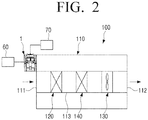
FIG. 2 is a conceptual view illustrating an electrical appliance including an electrostatic dust collecting device using carbon fibers according to an embodiment of the present disclosure; -
FIG. 3 is a perspective view illustrating a charging device of an electrostatic dust collecting device using carbon fibers according to an embodiment of the present disclosure; -
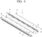
FIG. 4 is an exploded perspective view illustrating the charging device ofFIG. 3 ; -
FIG. 5 is a cross-sectional view illustrating the charging device ofFIG. 3 ; -
FIG. 6 is a rear perspective view illustrating the charging device ofFIG. 3 ; -
FIG. 7 is a perspective view illustrating a printed circuit board of the charging device ofFIG. 3 on which a plurality of carbon fiber electrodes are disposed; -
FIG. 8 is a graph comparing an electron generation amount of a charging device according to an embodiment of the present disclosure having a ground electrode with an electron generation amount of a conventional charging device without a ground electrode; -
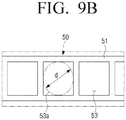
FIGS. 9A ,9B ,9C ,9D ,9E ,9F , and9G are views illustrating various patterns of a protection grille of a charging device according to an embodiment of the present disclosure; -
FIG. 10 is a cross-sectional view illustrating an example of a charging device of an electrostatic dust collecting device using carbon fibers according to an embodiment of the present disclosure; -
FIG. 11 is a cross-sectional view illustrating an example of a charging device of an electrostatic dust collecting device using carbon fibers according to an embodiment of the present disclosure; -
FIG. 12 is a cross-sectional view illustrating an example of a charging device of an electrostatic dust collecting device using carbon fibers according to an embodiment of the present disclosure; -
FIG. 13 is a cross-sectional view illustrating an example of a charging device of an electrostatic dust collecting device using carbon fibers according to an embodiment of the present disclosure; -
FIG. 14 is a perspective view illustrating an indoor part of an air conditioner having an electrostatic dust collecting device using carbon fibers according to an embodiment of the present disclosure; -
FIG. 15 is a cross-sectional view illustrating the indoor part of the air conditioner ofFIG. 14 ; -
FIG. 16 is a conceptual view illustrating an electrical appliance including an electrostatic dust collecting device using carbon fibers according to an embodiment of the present disclosure; -
FIG. 17 is a cross-sectional view conceptually illustrating an example of a dust collecting device used in the electrical appliance ofFIG. 16 ; -
FIG. 18 is a perspective view illustrating a charging device of an electrostatic dust collecting device using carbon fibers according to an embodiment of the present disclosure having a plurality of electron blocking plates; -
FIG. 19 is an exploded perspective view illustrating a charging device and a charging device holder of an electrostatic dust collecting device using carbon fibers according to an embodiment of the present disclosure having a plurality of electron blocking plates; -
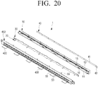
FIG. 20 is an exploded perspective view illustrating a charging device having a protection grille in which a plurality of electron blocking plates are provided; -
FIG. 21 is an exploded perspective view illustrating a charging device having a housing in which a plurality of electron blocking plates are provided; -
FIG. 22 is a conceptual view illustrating a state in which electrons emitted from a carbon fiber electrode are blocked by an electron blocking plate; -
FIG. 23 is a conceptual view illustrating a state in which electrons emitted from a carbon fiber electrode are blocked by an electron blocking plate; -
FIG. 24 is a partial perspective view illustrating a state in which a charging device having a plurality of electron blocking plates of an electrostatic dust collecting device using carbon fibers according to an embodiment of the present disclosure is disposed in an indoor part of an air conditioner; -
FIG. 25 is a view illustrating a region where electrons generated in a carbon fiber electrode move directly to a dust collecting device when a charging device has an electron blocking plate; -
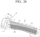
FIG. 26 is a view illustrating a region where electrons generated in a carbon fiber electrode move directly to a dust collecting device when a charging device does not include an electron blocking plate; -
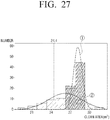
FIG. 27 is a histogram and a normal distribution graph comparing of clear areas of a case where an electrostatic dust collecting device using carbon fibers according to an embodiment of the present disclosure is provided with electron blocking plates and a case where the electron blocking plates are not provided; and -
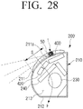
FIG. 28 is a cross-sectional view illustrating an indoor part of an air conditioner including an electrostatic dust collecting device using carbon fibers according to an embodiment of the present disclosure. - Hereinafter, various embodiments of the present disclosure will be described in detail with reference to the accompanying drawings.
- It should be understood that the disclosure is not limited to the example embodiments described hereinafter, but includes various modifications, equivalents, and/or alternatives of the examples of the disclosure. The scope of the invention is defined by the appended claims. In relation to explanation of the drawings, similar drawing reference numerals may be used for similar constituent elements. Further, dimensions of various elements in the accompanying drawings may be arbitrarily increased or decreased for assisting in a comprehensive understanding.
- In the disclosure, the terms "first, second, and so forth" are used to describe diverse elements regardless of their order and/or importance and to discriminate one element from other elements, but are not limited to the corresponding elements. For example, a first user appliance and a second user appliance may indicate different user appliances regardless of their order or importance. For example, without departing from the scope of the disclosure, the first element may be called the second element, and the second element may be called the first element in a similar manner.
- The terms used in the disclosure are used to merely describe various examples, but is not intended to limit the scope of other examples. In the disclosure, a singular expression may include a plural expression unless specially described. All terms (including technical and scientific terms) used in the disclosure could be used as commonly understood by those ordinary skilled in the art to which the disclosure belongs. The terms that are used in the disclosure and are defined in a general dictionary may be used as meanings that are identical or similar to the meanings of the terms from the context of the related art, and they are not interpreted ideally or excessively unless they have been clearly and specially defined. Even the wordings that are defined in the present disclosure must not be interpreted to exclude all examples of the disclosure.
- Hereinafter, an electrical appliance including an electrostatic dust collecting device using carbon fibers an embodiment of the present disclosure will be described in detail with reference to the accompanying drawings.
-
FIG. 2 is a conceptual view illustrating an electrical appliance including an electrostatic dust collecting device using carbon fibers according to an embodiment of the present disclosure. - Referring to
FIG. 2 , anelectrical appliance 100 including an electrostatic dust collecting device using carbon fibers according to an embodiment of the present disclosure may include amain body 110, acharging device 1, anair moving device 130, and adust collecting device 120. - The
main body 110 forms an outer shape of theelectrical appliance 100 and may have various shapes depending on the type of theelectrical appliance 100. Theelectrical appliance 100 may be any one of an air purifier, an air conditioner, a dehumidifier, a humidifier, a clothes manager, a refrigerator, a dryer, and the like. Themain body 110 may be provided with aninlet 111 through which outside air is sucked, anoutlet 112 through which the sucked air is exhausted, and anair passage 113 connecting theinlet 111 and theoutlet 112. - The charging
device 1 is provided near theinlet 111 of themain body 110 and is configured to charge contaminants such as dust contained in the air sucked into theinlet 111 using carbon fibers. The chargingdevice 1 may be disposed on the outer surface of themain body 110 at the edge of theinlet 111. In other words, the chargingdevice 1 may be disposed on the outer surface of themain body 110 so as not to interfere with the projection area of theinlet 111. When thecharging device 1 is provided outside theinlet 111 so that thecharging device 1 does not block theinlet 111, the amount of air sucked into theinlet 111 is not reduced. The configuration of thecharging device 1 will be described in detail below. - The
air moving device 130 is disposed inside themain body 110 and is configured to suck outside air containing contaminants through theinlet 111 and to exhaust the outside air to the outside of themain body 110. In other words, when theair moving device 130 operates, air containing contaminants is introduced into theinlet 111 of themain body 110, flows along theair passage 113, and is exhausted through theoutlet 112. Theair moving device 130 may use a fan that can generate a suction force capable of sucking air. - The
dust collecting device 120 is disposed in theair passage 113 provided inside themain body 110 and is configured to collect the contaminants charged by the chargingdevice 1 from the air sucked by theair moving device 130. For example, thedust collecting device 120 may include a plurality of dust collecting plates spaced by a predetermined distance apart from each other and a dust collecting voltage applier configured to apply a high voltage to the plurality of dust collecting plates. When a high voltage is applied to the plurality of dust collecting plates by the dust collecting voltage applier, the contaminants charged in combination with electrons generated in thecharging device 1 may be collected in the plurality of dust collecting plates. Therefore, because the contaminants contained in the sucked outside air are removed by thedust collecting device 120, cleaned air is exhausted from thedust collecting device 120. - The charging
device 1, thedust collecting device 120, and theair moving device 130 as described above may constitute an electrostatic dust collecting device using carbon fibers according to an embodiment of the present disclosure. - The
main body 110 may further include aprocessing part 140 that performs a predetermined process on the sucked air. For example, when theelectrical appliance 100 is implemented as an air conditioner, themain body 110 may be provided with a heat exchanger capable of performing heat exchange with the sucked air as theprocessing part 140. When theelectrical appliance 100 is a dehumidifier, themain body 110 may be provided with a dehumidifying device capable of removing moisture from the sucked air as theprocessing part 140. In addition, when theelectrical appliance 100 is a humidifier, themain body 110 may be provided with a humidifying device capable of adding moisture to the sucked air as theprocessing part 140. - In the case where the
electrical appliance 100 is an air cleaner implemented by an electrostatic dust collecting device according to an embodiment of the present disclosure, theprocessing part 140 may not exist in themain body 110. - When the
electrical appliance 100 is a clothes manager, a refrigerator, a dryer, or the like, to which the electrostatic dust collecting device according to an embodiment of the present disclosure is additionally provided, theprocessing part 140 may not be included inside themain body 110. - Hereinafter, the charging
device 1 used in the electrostatic dust collecting device using carbon fibers according to an embodiment of the present disclosure will be described in detail with reference toFIGS. 3 to 7 . -
FIG. 3 is a perspective view illustrating a charging device of an electrostatic dust collecting device using carbon fibers according to an embodiment of the present disclosure.FIG. 4 is an exploded perspective view illustrating the charging device ofFIG. 3 , andFIG. 5 is a cross-sectional view illustrating the charging device ofFIG. 3 .FIG. 6 is a rear perspective view illustrating the charging device ofFIG. 3 .FIG. 7 is a perspective view illustrating a printed circuit board of the charging device ofFIG. 3 on which a plurality of carbon fiber electrodes are disposed. - Referring to
FIGS. 3 to 7 , the chargingdevice 1 of the electrostatic dust collecting device using carbon fibers according to an embodiment of the present disclosure may include ahousing 10, a plurality ofcarbon fiber electrodes 20, a printedcircuit board 30, and aground electrode 40. - The
housing 10 is formed to accommodate the plurality ofcarbon fiber electrodes 20 and the printedcircuit board 30. Anopening 11 is formed on one surface of thehousing 10 facing the tips of the plurality ofcarbon fiber electrodes 20, that is, on the front surface of thehousing 10. Arear opening 13 may be provided on the opposite side of the one surface of thehousing 10, that is, on the rear surface of thehousing 10. The plurality ofcarbon fiber electrodes 20 may be exposed through theopening 11 of thehousing 10. Therefore, thehousing 10 is formed so that the outside air can flow through the inside of thehousing 10. - In the case of the present embodiment, as illustrated in
FIG. 4 , thehousing 10 is formed in a substantially hollow rectangular parallelepiped shape having a long length. The printedcircuit board 30 to which the plurality ofcarbon fiber electrodes 20 are fixed is provided inside thehousing 10. - The plurality of
carbon fiber electrodes 20 are configured to generate electrons at the tip of each of thecarbon fiber electrodes 20 when a high voltage is applied thereto. The plurality ofcarbon fiber electrodes 20 are disposed such that the tips of thecarbon fiber electrodes 20 face theopening 11 of thehousing 10. Therefore, the electrons generated from the plurality ofcarbon fiber electrodes 20 are emitted to the outside through theopening 11 of thehousing 10. When thecharging device 1 is disposed in theelectrical appliance 100 such that theopening 11 of thehousing 10 faces theinlet 111 of themain body 110 as illustrated inFIG. 2 , the tips of the plurality ofcarbon fiber electrodes 20 are arranged to face theinlet 111. Accordingly, because electrons generated from the plurality ofcarbon fiber electrodes 20 are emitted to the outside through theopening 11 of thehousing 10, the contaminants contained in the air sucked into theinlet 111 may be charged. - The plurality of
carbon fiber electrodes 20 are provided on the printedcircuit board 30 at regular intervals. The plurality ofcarbon fiber electrodes 20 are arranged on the printedcircuit board 30 in a straight line. In addition, the plurality ofcarbon fiber electrodes 20 are disposed on the printedcircuit board 30 at the same height. - The printed
circuit board 30 is provided with apower supply line 31 capable of applying power to the plurality ofcarbon fiber electrodes 20. A highvoltage applying part 60 is connected to thepower supply line 31 of the printedcircuit board 30. Therefore, a high voltage may be applied to the plurality ofcarbon fiber electrodes 20 through thepower supply line 31 of the printedcircuit board 30. For example, the highvoltage applying part 60 may be configured to apply a voltage of about 6 kV to the plurality ofcarbon fiber electrodes 20 through thepower supply line 31 of the printedcircuit board 30. - The printed
circuit board 30 may be provided with a plurality of holes through which the air drawn intohousing 10 passes. In the present embodiment, as illustrated inFIG. 7 , a plurality of notchedportions 33 through which air passes are provided on both side surfaces of the printedcircuit board 30. Therefore, the plurality of notchedportions 33 of the printedcircuit board 30 performs the function of a plurality of holes through which the air passes. The printedcircuit board 30 is formed in a rectangular plate corresponding to theopening 11 of thehousing 10 so that the printedcircuit board 30 may be inserted into thehousing 10. The plurality of notchedportions 33 having a predetermined depth are formed on both side surfaces of the printedcircuit board 30. Thus, the air introduced into thehousing 10 may flow through the plurality of notchedportions 33 of the printedcircuit board 30. - In addition, the printed
circuit board 30 is supported by a plurality of supportingportions 16 provided inside thehousing 10. The plurality of supportingportions 16 may be provided on the inner surfaces of the upper surface and the lower surface of thehousing 10 so as to support the printedcircuit board 30. In addition, acenter supporting portion 17 may be provided on the inner surface of each of both ends of thehousing 10 to support the both ends of the printedcircuit board 30. - The plurality of
carbon fiber electrodes 20 may include an appropriate number ofcarbon fiber electrodes 20 to emit electrons to all the air sucked into theinlet 111 of themain body 110. In the embodiment shown inFIGS. 4 and7 , sixcarbon fiber electrodes 20 are provided on the printedcircuit board 30, but this is merely an example. The number of the plurality ofcarbon fiber electrodes 20 and the distance between the two adjacentcarbon fiber electrodes 20 may be appropriately determined depending on the size of theinlet 111 of themain body 110 in which thecharging device 1 is disposed. - In addition, the printed
circuit board 30 is formed to have a length capable of supporting the plurality ofcarbon fiber electrodes 20 arranged in a single line. For example, the printedcircuit board 30 on which the plurality ofcarbon fiber electrodes 20 are disposed may be formed to have a length equal to or greater than 1/3 of the length of theinlet 111 of themain body 110. - Each of the plurality of
carbon fiber electrodes 20 may include anelectrode bar 21 fixed to the printedcircuit board 30 and a plurality ofcarbon fibers 22 disposed at the tip of theelectrode bar 21. - The
electrode bar 21 may be formed in a substantially cylindrical shape so as to support the plurality ofcarbon fibers 22 and be fixed to the printedcircuit board 30. In other words, one end of theelectrode bar 21 is fixed to the printedcircuit board 30, and the plurality ofcarbon fibers 22 are provided at the other end of theelectrode bar 21. Further, theelectrode bar 21 is electrically connected to thepower supply line 31 of the printedcircuit board 30. Theelectrode bar 21 may be formed of a conductive material to apply power to the plurality ofcarbon fibers 22. - In the present embodiment, the
electrode bar 21 is formed in a cylindrical shape having a circular cross-section, but the shape of theelectrode bar 21 is not limited thereto. Theelectrode bar 21 may be formed in various shapes as long as theelectrode bar 21 can fix the plurality ofcarbon fibers 22 to the printedcircuit board 30. As an example, theelectrode bar 21 may be formed in a columnar shape having a cross-section of a polygonal shape such as a quadrangle, a pentagon, and the like, or an elliptical shape. - The plurality of
carbon fibers 22 are fixed to one end of theelectrode bar 21 in the form of a bundle. In other words, the plurality ofcarbon fibers 22 may have a brush shape. The plurality ofcarbon fibers 22 are spaced apart from each other so as not to contact each other. Each of the plurality ofcarbon fibers 22 may be formed to have a diameter of about 6 µm to 8 µm. - Therefore, when a high voltage is applied to the printed
circuit board 30, electrons are emitted from the tips of the plurality ofcarbon fibers 22 and charge the contaminants contained in the air. In other words, the electrons emitted from the tips of the plurality ofcarbon fibers 22 are combined with contaminants c to charge the contaminants to become anions (negative ions) c- (e- + c = c-). - The
ground electrode 40 maintains a predetermined potential difference between each of the plurality ofcarbon fiber electrodes 20 and the surrounding air so that a predetermined amount of electrons is generated from the plurality ofcarbon fiber electrodes 20 even after a lapse of time. For this purpose, theground electrode 40 is disposed around the plurality ofcarbon fiber electrodes 20. For example, theground electrode 40 may be disposed in the vicinity of the printedcircuit board 30 so as not to face the tips of the plurality ofcarbon fiber electrodes 20. In other words, theground electrode 40 may be disposed behind the printedcircuit board 30 on the opposite side of one side surface of the printedcircuit board 30 on which the plurality ofcarbon fiber electrodes 20 are provided or the plurality ofcarbon fiber electrodes 20. - For example, as illustrated in
FIGS. 5 and6 , theground electrode 40 may be disposed on the rear surface of thehousing 10. To this end, anelectrode fixing portion 18 to which theground electrode 40 is fixed may be provided on the rear surface of thehousing 10. Thus, theground electrode 40 may be disposed on the rear surface of thehousing 10 spaced apart by a predetermined distance from the opposite surface of the printedcircuit board 30 opposite to the plurality ofcarbon fiber electrodes 20 provided on one surface of the printedcircuit board 30. At this time, therear opening 13 of thehousing 10 may be provided on the rear surface of thehousing 10 on both sides of theground electrode 40. - The
ground electrode 40 is formed of a conductive thin metal plate and is formed to have a length corresponding to the length of the printedcircuit board 30 so that all of the plurality ofcarbon fiber electrodes 20 may maintain a predetermined potential difference. As illustrated inFIG. 4 , in the case of the present embodiment, theground electrode 40 is formed of a thin strip-shaped metal plate. - In addition, the
ground electrode 40 may include a plurality of throughholes 41. A plurality of fixingpins 18a corresponding to the plurality of throughholes 41 of theground electrode 40 are provided in theelectrode fixing portion 18 of thehousing 10. Therefore, when the plurality of fixingpins 18a of thehousing 10 are inserted into the plurality of throughholes 41 of theground electrode 40, theground electrode 40 is fixed to theelectrode fixing portion 18 of thehousing 10. - The
ground electrode 40 is connected to anexternal ground 70. For example, theground electrode 40 may be connected to theexternal ground 70 by connecting a ground wire (not illustrated) connected to theground 70 of an external power source to oneend 43 of theground electrode 40. As described above, when theground electrode 40 is connected to theexternal ground 70, ions saturated in the periphery of the plurality ofcarbon fiber electrodes 20 are discharged to theexternal ground 70 through theground electrode 40, so that the periphery of theground electrode 40 may maintain a predetermined potential difference. Therefore, the plurality ofcarbon fiber electrodes 20 may always generate electrons stably regardless of the passage of time. - The inventors conducted experiments to compare the amount of electrons generated in the
charging device 1 according to an embodiment of the present disclosure having theground electrode 40 and the amount of electrons generated in the conventional charging device without the ground electrode. -
FIG. 8 is a graph comparing an electron generation amount of a charging device according to an embodiment of the present disclosure having a ground electrode with an electron generation amount of a conventional charging device without a ground electrode. - In
FIG. 8 , the horizontal axis represents time (minute), and the vertical axis represents electron generation amount. Further, inFIG. 8 , thethin line ① represents the amount of electrons generated in the conventional charging device without the ground electrode, and the thick line (2) represents the amount of electrons generated in thecharging device 1 according to an embodiment of the present disclosure having theground electrode 40. - Referring to the thick line (2) in
FIG. 8 , the chargingdevice 1 according to an embodiment of the present disclosure maintains the electron generation amount constant within a range of about 3,600,000 to about 5,000,000 even after an extended amount of time, so that electrons are uniformly generated. - However, referring to the
thin line ① inFIG. 8 , the conventional charging device maintains the electron generation amount in the range of about 3,600,000 to about 5,000,000 similarly to thecharging device 1 of the present disclosure up to about 50 minutes. However, from the point of time exceeding 60 minutes, the amount of electrons generated in the charging device sharply decreases to about 2,000,000 or less, and the electron generation amount intermittently becomes almost zero. In other words, in the conventional charging device without the ground electrode, it can be seen that the electron generation amount is uneven as time passes. - Therefore, the charging
device 1 according to an embodiment of the present disclosure having theground electrode 40 may have a stabilized electron generation amount compared with the conventional charging device without the ground electrode. - In the case in which the plurality of
carbon fiber electrodes 20 are exposed to the outside, when a user cleans theelectrical appliance 100 equipped with the electrostatic dust collecting device using carbon fibers according to an embodiment of the present disclosure, a hand or a part of the body of the user may contact the plurality ofcarbon fiber electrodes 20. At this time, because a high voltage is applied to the plurality ofcarbon fiber electrodes 20, the user may be subjected to electric shock when the hand or a part of the body touches thecarbon fiber electrodes 20. - A
protection grille 50 may be disposed in theopening 11 of the front surface of thehousing 10 facing the plurality ofcarbon fiber electrodes 20 in order to prevent the electric shock. Theprotection grille 50 blocks the user's hand or finger from contacting thecarbon fiber electrodes 20. Theprotection grille 50 may be formed in various patterns that block the user's hand or finger and allow air and electrons generated from the plurality ofcarbon fiber electrodes 20 to pass through. - Referring to
FIGS. 3 and4 , theprotection grille 50 is formed in a substantially hollow rectangular parallelepiped shape having a long length. The front surface of theprotection grille 50 is provided with apattern portion 51 through which air may be drawn and electrons may be emitted. The rear surface of theprotection grille 50 coupled to thehousing 10 is open. - A plurality of fixing protrusions for fixing the printed
circuit board 30 to thehousing 10 may be provided at a rear end of theprotection grille 50. When theprotection grille 50 is coupled to theopening 11 of thehousing 10, thepattern portion 51 of theprotection grille 50 is spaced apart by a predetermined distance from the tips of the plurality ofcarbon fiber electrodes 20 and the printedcircuit board 30 is fixed to the inside of thehousing 10. Therefore, there is a certain gap between the inner surface of the front surface of theprotection grille 50 and the tips of the plurality ofcarbon fiber electrodes 20 fixed to thehousing 10. - In addition, a plurality of fixing hooks 55 for coupling the
protection grille 50 to thehousing 10 may be provided on the upper surface and the lower surface of the rear end of theprotection grille 50. A plurality of fixinggrooves 15 to which the plurality of fixing hooks 55 of theprotection grille 50 are coupled may be provided on the upper surface and the lower surface of the front end of thehousing 10 corresponding thereto. - On the other hand, the
pattern portion 51 of theprotection grille 50 may be formed in variouspatterns having holes 53 that blocks the user's hand or finger and through which air and electrons pass. -
FIGS. 9A ,9B ,9C ,9D ,9E ,9F , and9G are views illustrating various patterns of a protection grille of a charging device according to an embodiment of the present disclosure. - As illustrated in
FIG. 9A , thepattern portion 51 of theprotection grille 50 of thecharging device 1 may be formed in a triangular pattern in which a plurality oftriangular holes 53 are continuously formed. At this time, the diameter d of the inscribedcircle 53a of each of the plurality oftriangular holes 53 may not exceed about 6 mm. - As illustrated in
FIG. 9B , thepattern portion 51 of theprotection grille 50 of thecharging device 1 may be formed in a rectangular pattern in which a plurality ofrectangular holes 53 are continuously formed. At this time, the diameter d of the inscribedcircle 53a of each of the plurality ofrectangular holes 53 may not exceed about 6 mm. - As illustrated in
FIG. 9C , thepattern portion 51 of theprotection grille 50 of thecharging device 1 may be formed in a regular hexagonal pattern in which a plurality of regularhexagonal holes 53 are continuously formed, that is, in a honeycomb pattern. At this time, the diameter d of the inscribedcircle 53a of each of the plurality of regularhexagonal holes 53 may not exceed about 6 mm. - As illustrated in
FIG. 9D , thepattern portion 51 of theprotection grille 50 of thecharging device 1 may be formed in a pentagonal pattern in which a plurality ofpentagonal holes 53 are continuously formed. At this time, the diameter d of the inscribedcircle 53a of each of the plurality ofpentagonal holes 53 may not exceed about 6 mm. - As illustrated in
FIG. 9E , thepattern portion 51 of theprotection grille 50 of thecharging device 1 may be formed in a rhombic pattern in which a plurality ofrhombic holes 53 are continuously formed. At this time, the diameter d of the inscribedcircle 53a of each of the plurality ofrhombic holes 53 may not exceed about 6 mm. - As illustrated in
FIG. 9F , thepattern portion 51 of theprotection grille 50 of thecharging device 1 may be formed in a circular pattern in which a plurality ofcircular holes 53 are continuously formed. At this time, the diameter d of each of the plurality ofcircular holes 53 may not exceed about 6 mm. - As illustrated in
FIG. 9G , thepattern portion 51 of theprotection grille 50 of thecharging device 1 may be formed in an elliptical pattern in which a plurality ofelliptical holes 53 are continuously formed. At this time, the diameter d of the inscribedcircle 53a of each of the plurality ofelliptical holes 53 may not exceed about 6 mm. - As described above, when the
protection grille 50 is provided in theopening 11 of the front surface of thehousing 10 in which the plurality ofcarbon fiber electrodes 20 are accommodated, a part of the body such as the user's finger may be blocked from contacting the plurality ofcarbon fiber electrodes 20 to be subjected to electric shock. In addition, electrons generated from the plurality ofcarbon fiber electrodes 20 are emitted to the outside through the plurality ofholes 53 provided in thepattern portion 51 of theprotection grille 50, thereby effectively charging the contaminants contained in the air passing in front of theprotection grille 50. - In the above description, the
protection grille 50 is formed in a rectangular parallelepiped shape having a long length and thepattern portion 51 is formed on the front surface of theprotection grille 50. However, the shape of theprotection grille 50 is not limited thereto. As an example, as illustrated inFIG. 10 , theprotection grille 50 may be formed in a flat plate shape having thepattern portion 51. -
FIG. 10 is a cross-sectional view illustrating an example of a charging device of an electrostatic dust collecting device using carbon fibers according to an embodiment of the present disclosure. - A plurality of
carbon fiber electrodes 20, a printedcircuit board 30, and aground electrode 40 of the charging device 1' ofFIG. 10 are the same as those of thecharging device 1 according to the above-described embodiment except for the shape of the housing 10' and the protection grille 50'. Therefore, detailed descriptions thereof is omitted. - Referring to
FIG. 10 , the housing 10' is formed in a substantially hollow rectangular parallelepiped shape having a long length and anopening 11 through which the plurality ofcarbon fiber electrodes 20 are exposed is provided on the front surface of the housing 10'. The front end of the housing 10' is formed higher than the tips of the plurality ofcarbon fiber electrodes 20. Therefore, inFIG. 10 , the tips of the plurality ofcarbon fiber electrodes 20 are positioned behind theopening 11 of the housing 10'. In addition, anelectrode fixing portion 18 on which theground electrode 40 is disposed is provided on the rear surface of the housing 10' and arear opening 13 is provided on both sides of theelectrode fixing portion 18. - The protection grille 50' is formed in a flat plate shape and is disposed in the
opening 11 of the housing 10' to cover theopening 11 of the front surface of the housing 10'. The rear surface of the protection grille 50' is spaced apart by a predetermined distance from the tips of the plurality ofcarbon fiber electrodes 20. The protection grille 50' is provided withvarious pattern portion 51 forming a plurality ofholes 53 that prevent the user's hand or finger from contacting the plurality ofcarbon fiber electrodes 20 and through which the air can be introduced. For example, the protection grille 50' may be formed in various patterns as illustrated inFIGS. 9A to 9G . - In the above description, the
ground electrode 40 is provided on the rear surface of thehousing 10 and 10' of thecharging device 1 and 1'. However, the position of theground electrode 40 of the charging device according to an embodiment of the present disclosure is not limited thereto. Hereinafter, various arrangements of theground electrode 40 will be described in detain with reference toFIGS. 11 to 13 . -
FIG. 11 is a cross-sectional view illustrating an example of a charging device of an electrostatic dust collecting device using carbon fibers according to an embodiment of the present disclosure. - Referring to
FIG. 11 , acharging device 2 of an electrostatic dust collecting device according to an embodiment of the present disclosure may include ahousing 10", a plurality ofcarbon fiber electrodes 20, a printedcircuit board 30, and aground electrode 40. - The plurality of
carbon fiber electrodes 20 and the printedcircuit board 30 are the same as or similar to those of thecharging device 1 according to the above-described embodiment, and therefore, detailed description thereof is omitted. - The
housing 10" is formed to accommodate the plurality ofcarbon fiber electrodes 20, the printedcircuit board 30, and the ground electrode 40'. In other words, thehousing 10" is formed in a hollow rectangular parallelepiped shape having a long length. Anopening 11 is provided on the front surface of thehousing 10" facing the tips of the plurality ofcarbon fiber electrodes 20 disposed on the printedcircuit board 30. Arear opening 13 is provided on the rear surface of thehousing 10". The tips of the plurality ofcarbon fiber electrodes 20 are disposed to face theopening 11 of thehousing 10". Therefore, thehousing 10" may be formed so that the air flows through the inside of thehousing 10". - A
protection grille 50 is disposed in theopening 11 of the front surface of thehousing 10" to prevent an electric shock. Theprotection grille 50 may be formed to haveholes 53 that block the user's hand or finger and through which air can pass. - For example, the
protection grille 50 is formed in a substantially hollow rectangular parallelepiped shape having a long length. The front surface of theprotection grille 50 is provided with apattern portion 51 that blocks the user's hand or finger and through which air can pass. The rear end of theprotection grille 50 may be connected to theopening 11 of thehousing 10". - When the
protection grille 50 is coupled to theopening 11 of thehousing 10", thepattern portion 51 of theprotection grille 50 is spaced apart by a predetermined distance from the tips of the plurality ofcarbon fiber electrodes 20. In other words, there is a certain gap between the inner surface of the front surface of theprotection grille 50 and the tips of the plurality ofcarbon fiber electrodes 20. Thepattern portion 51 of theprotection grille 50 may be formed in variouspatterns having holes 53 that block the user's hand or finger and through which the air can pass as illustrated inFIGS. 9A to 9G . - The ground electrode 40' is disposed on the inside of the
upper surface 10a of thehousing 10" spaced apart by a predetermined distance from the opposite surface of the printedcircuit board 30 opposite to the plurality ofcarbon fiber electrodes 20 provided on one surface of the printedcircuit board 30. The ground electrode 40' may be formed of a thin conductive metal plate and may have a length corresponding to the length of the printedcircuit board 30 so that the plurality ofcarbon fiber electrodes 20 maintain a predetermined potential difference, respectively. -
FIG. 12 is a cross-sectional view illustrating an example of a charging device of an electrostatic dust collecting device using carbon fibers according to an embodiment of the present disclosure. - Referring to
FIG. 12 , a charging device 2' of an electrostatic dust collecting device according to an embodiment of the present disclosure may include ahousing 10", a plurality ofcarbon fiber electrodes 20, a printedcircuit board 30, and a ground electrode 40'. - The charging device 2' illustrated in
FIG. 12 is the same as thecharging device 2 illustrated inFIG. 11 described above, except that the ground electrode 40' is provided on the inner surface of thelower surface 10b of thehousing 10"; therefore, the detailed description thereof is omitted. -
FIG. 13 is a cross-sectional view illustrating an example of a charging device of an electrostatic dust collecting device using carbon fibers according to an embodiment of the present disclosure. - Referring to
FIG. 13 , acharging device 3 of an electrostatic dust collecting device according to an embodiment of the present disclosure may include ahousing 310, a plurality ofcarbon fiber electrodes 320, a printedcircuit board 330, and aground electrode 340. - The
housing 310 is formed in a substantially hollow rectangular parallelepiped shape having a long length and anopening 311 through which the plurality ofcarbon fiber electrodes 320 are exposed is provided on the front surface of thehousing 310. The front end of thehousing 310 is formed to be higher than the tips of the plurality ofcarbon fiber electrodes 320. Therefore, inFIG. 13 , thetips 320a of the plurality ofcarbon fiber electrodes 320 are positioned behind theopening 311 of thehousing 310. In addition, the rear surface of thehousing 310 is provided with arear opening 313 through which air is passed. - The plurality of
carbon fiber electrodes 320 are disposed on the printedcircuit board 330 such that thetips 320a thereof face theopening 311 of thehousing 310. The plurality ofcarbon fiber electrodes 320 are disposed on the printedcircuit board 330 to form a straight line at regular intervals. Further, the plurality ofcarbon fiber electrodes 320 are provided on the printedcircuit board 330 such that thetips 320a thereof are positioned on the same plane. - The plurality of
carbon fiber electrodes 320 are disposed parallel to the printedcircuit board 330. In other words, a plurality ofcarbon fibers 322 and anelectrode bar 321 forming thecarbon fiber electrode 320 are provided in parallel to the printedcircuit board 330. Therefore, theelectrode bar 321 to which the plurality ofcarbon fibers 322 are fixed is fixed to the printedcircuit board 330 by asupport protrusion 323. Accordingly, the power supplied to the printedcircuit board 330 is applied to the plurality ofcarbon fibers 322 through thesupport protrusion 323 and theelectrode bar 321. - The
ground electrode 340 is provided at a side of the plurality ofcarbon fiber electrodes 320 on the printedcircuit board 330. Accordingly, the printedcircuit board 330 is provided with apower supply line 331 for supplying power to the plurality ofcarbon fiber electrodes 320 and aground line 332 to which theground electrode 340 is connected. Theground electrode 340 is provided on the opposite side of the plurality ofcarbon fibers 322 based on the electrode bars 321 of the plurality ofcarbon fiber electrodes 320. In other words, the plurality ofcarbon fiber electrodes 320 are disposed on the printedcircuit board 330 so as to face theopening 311 of thehousing 310, and theground electrode 340 is disposed on the printedcircuit board 330 so as to be adjacent to therear opening 313 of thehousing 310. - Further, the
ground electrode 340 is formed of a conductive thin metal plate. Theground electrode 340 may be formed to have a length corresponding to the length of the printedcircuit board 330 so that the plurality ofcarbon fiber electrodes 320 fixed to the printedcircuit board 330 may maintain a predetermined potential difference, respectively. - On the other hand, the printed
circuit board 330 is fixed to the lower surface of thehousing 310 with reference toFIG. 13 . Accordingly, the printedcircuit board 330 does not prevent air from flowing through theopening 311 and therear opening 313 of thehousing 310. - In addition, a
protection grille 350 is disposed in theopening 311 of the front surface of thehousing 310 to prevent electric shock. Theprotection grille 350 may be formed to haveholes 353 that may block the user's hand or finger and through which air can pass. - The
protection grille 350 is formed in a flat plate shape and is disposed in theopening 311 of thehousing 310 so as to cover theopening 311 of the front surface of thehousing 310. The rear surface of theprotection grille 350 is spaced apart by a certain distance from thetips 320a of the plurality ofcarbon fiber electrodes 320. Theprotection grille 350 is provided withvarious pattern portions 351 forming a plurality ofholes 353 that prevent the user's hand or finger from contacting the plurality ofcarbon fiber electrodes 320 and through which the air may be introduced. For example, theprotection grille 350 may be formed in various patterns as illustrated inFIGS. 9A to 9G . - Hereinafter, a case where the electrostatic dust collecting device using carbon fibers according to an embodiment of the present disclosure as described above is applied to an indoor part of an air conditioner will be described in detail with reference to
FIGS. 14 and15 . -
FIG. 14 is a perspective view illustrating an indoor part of an air conditioner having an electrostatic dust collecting device using carbon fibers according to an embodiment of the present disclosure, andFIG. 15 is a cross-sectional view illustrating the indoor part of the air conditioner ofFIG. 14 . - Referring to
FIGS. 14 and15 , anindoor part 200 of an air conditioner having the electrostatic dust collecting device using carbon fibers according to an embodiment of the present disclosure may include acase 210, acharging device 1, adust collecting device 220, aheat exchanger 240, and a blowingfan 230. - The
case 210 forms the appearance of theindoor part 200 of the air conditioner. Thecase 210 includes aninlet 211 through which outside air is introduced and anoutlet 212 through which the air, which exchanged heat with theheat exchanger 240, is exhausted. Thecase 210 is provided with anair passage 213 that allows theinlet 211 and theoutlet 212 to be communicated with each other and through which the sucked outside air passes. - The charging
device 1 is disposed on the outer surface of thecase 210 so as to be adjacent to theinlet 211. The chargingdevice 1 is configured to charge contaminants such as dust contained in the air flowing into theinlet 211 by using carbon fibers. The chargingdevice 1 may be disposed on the outer surface of thecase 210 at a position where thecharging device 1 does not interfere with the projection area S of theinlet 211, that is, at the edge of theinlet 211. For example, as illustrated inFIG. 15 , the chargingdevice 1 may be disposed so that theprotection grille 50 of thecharging device 1 does not extend beyond the oneend 211a of theinlet 211 of thecase 210. In other words, one end of thecharging device 1 may be coincided with oneend 211a of theinlet 211 of thecase 210 or may be spaced apart from the oneend 211a of theinlet 211 by a certain distance. - When the
charging device 1 is disposed outside theinlet 211 so that thecharging device 1 does not block the inlet as described above, the amount of air sucked into theinlet 211 is not reduced. Therefore, the cooling and heating efficiency of theindoor part 200 may be prevented from being reduced by the chargingdevice 1 according to an embodiment of the present disclosure. - The charging
device 1 may include a printedcircuit board 30 on which the plurality ofcarbon fiber electrodes 20 are disposed, ahousing 10 in which the plurality ofcarbon fiber electrodes 20 and the printedcircuit board 30 are accommodated, aprotection grille 50 that is provided in theopening 11 of thehousing 10 and prevents the user from contacting the tips of the plurality ofcarbon fiber electrodes 20, and aground electrode 40 provided in thehousing 10. Such acharging device 1 is the same as thecharging device 1 described above; therefore, detailed description thereof is omitted. - The
dust collecting device 220 is provided in theair passage 213 inside thecase 210 and is configured to collect contaminants charged by the chargingdevice 1 from the air sucked by the blowingfan 230. Thedust collecting device 220 may include, for example, a plurality of dust collecting plates spaced apart from each other by a predetermined distance and a dust collecting voltage applier configured to apply a high voltage to the plurality of dust collecting plates. When a high voltage is applied to the plurality of dust collecting plates by the dust collecting voltage applier, contaminants charged in combination with electrons generated by the chargingdevice 1 may be collected in the plurality of dust collecting plates. - The
heat exchanger 240 adjusts the temperature of the air by performing heat exchange with the air sucked by the blowingfan 230. For example, when theindoor part 200 of the air conditioner cools the room, theheat exchanger 240 cools the air sucked by the blowingfan 230 to lower the temperature of the air. In addition, when theindoor part 200 of the air conditioner heats the room, theheat exchanger 240 heats the air sucked by the blowingfan 230 to increase the temperature of the air. Theheat exchanger 240 is the same as or similar to the heat exchanger used in the indoor part of the conventional air conditioner; therefore, a detailed description thereof is omitted. - The blowing
fan 230 is disposed inside thecase 210, and is configured so that outside air is sucked through theinlet 211, passes through theheat exchanger 240, and then is exhausted to the outside of thecase 210 through theoutlet 212. In other words, when the blowingfan 230 is operated, air containing contaminants is introduced into theinlet 111 of thecase 210, and the introduced air passes through thedust collecting device 220 and theheat exchanger 240 along theair passage 213, and then exhausted through theoutlet 112. Because the blowingfan 230 generates a suction force capable of sucking outside air, the blowingfan 230 may function as an air moving device of the electrostatic dust collecting device according to an embodiment of the present disclosure. - An operation of the
indoor part 200 of the air conditioner having the above-described structure will be described with reference toFIGS. 14 and15 . - When the
indoor part 200 is operated, a high voltage is applied from the high voltage applying part 60 (seeFIG. 2 ) to thecharging device 1 provided on the outer surface of thecase 210 adjacent to theinlet 211. When a high voltage is applied to thecharging device 1, electrons are emitted from the plurality ofcarbon fiber electrodes 20 of thecharging device 1. Electrons emitted from the chargingdevice 1 combine with contaminants in the air stream flowing into theinlet 211, thereby charging the contaminants. - In addition, when the
indoor part 200 is operated, the blowingfan 230 is operated so that the outside air F is introduced into thecase 210 through theinlet 211. At this time, the contaminants contained in the outside air flow F introduced into theinlet 211 are charged by the chargingdevice 1. - While the introduced outside air passes through the
dust collecting device 220, the charged contaminants are collected by thedust collecting device 220, and then the cleaned air moves to theheat exchanger 240. - The air cleaned by the
dust collecting device 220 exchanges heat with the refrigerant of theheat exchanger 240 while passing through theheat exchanger 240, so that the temperature of the air is adjusted. - The temperature-adjusted air passes through the blowing
fan 230 and is exhausted to the outside of theindoor part 200 through theoutlet 212 of thecase 210. - As described above, the
indoor part 200 of the air conditioner equipped with the electrostatic dust collecting device using carbon fibers according to an embodiment of the present disclosure may remove contaminants form sucked air and adjust the temperature of the air. - Hereinafter, an electrical appliance having an electrostatic dust collecting device using carbon fibers according to an embodiment of the present disclosure will be described with reference to
FIG. 16 . -
FIG. 16 is a conceptual view illustrating an electrical appliance including an electrostatic dust collecting device using carbon fibers according to an embodiment of the present disclosure. - Referring to
FIG. 16 , an electrical appliance 100' having an electrostatic dust collecting device using carbon fibers according to an embodiment of the present disclosure may include amain body 110, acharging device 1, anair moving device 130, adust collecting device 420, and a plurality ofelectron blocking plates 400. - The
main body 110 forms an outer shape of the electrical appliance 100' and may have various shapes depending on the type of the electrical appliance 100'. The electrical appliance 100' may be any one of an air purifier, an air conditioner, a dehumidifier, a humidifier, a clothes manager, a refrigerator, a dryer, and the like. Themain body 110 may be provided with aninlet 111 through which outside air is sucked, anoutlet 112 through which the sucked air is exhausted, and anair passage 113 connecting theinlet 111 and theoutlet 112. - The charging
device 1 is provided near theinlet 111 of themain body 110 and is configured to charge contaminants such as dust contained in the air sucked into theinlet 111 by using carbon fibers. The chargingdevice 1 may be disposed on the outer surface of themain body 110 at the edge of theinlet 111. In other words, the chargingdevice 1 may be disposed on the outer surface of themain body 110 so as not to interfere with the projection area of theinlet 111. When thecharging device 1 is provided outside theinlet 111 so that thecharging device 1 does not block theinlet 111, the amount of air sucked into theinlet 111 is not reduced. The configuration of thecharging device 1 will be described in detail below. - The
air moving device 130 is disposed inside themain body 110 and is configured to suck outside air containing contaminants through theinlet 111 and to exhaust the outside air to the outside of themain body 110. In other words, when theair moving device 130 operates, air containing contaminants is introduced into theinlet 111 of themain body 110, flows along theair passage 113, and is exhausted through theoutlet 112. A fan capable of generating a suction force capable of sucking air may be used as theair moving device 130. - The
dust collecting device 420 is disposed in theair passage 113 provided inside themain body 110 and is configured to collect the contaminants charged by the chargingdevice 1 from the air sucked by theair moving device 130. An example of thedust collecting device 420 is illustrated inFIG. 17 . -
FIG. 17 is a cross-sectional view conceptually illustrating an example of a dust collecting device used in the electrical appliance ofFIG. 16 . - Referring to
FIG. 17 , thedust collecting device 420 may include a plurality ofdust collecting plates 421 spaced apart from each other by a predetermined distance and a dustcollecting voltage applier 430 configured to apply a high voltage to the plurality ofdust collecting plates 421. - The
dust collecting plate 421 may include anelectrode 422 and insulatinglayers 423 laminated on the both side surfaces of theelectrode 422. In other words, thedust collecting plate 421 may be laminated in the order of the insulatinglayer 423, theelectrode 422, and the insulatinglayer 423. For example, theelectrode 422 may be formed of a carbon electrode, and the insulatinglayers 423 may be formed of polyethylene terephthalate (PET) film on both side surfaces of theelectrode 422. However, the kind ofelectrode 422 and the insulatinglayers 423 constituting thedust collecting plates 421 is not limited thereto. Theelectrode 422 and the insulatinglayers 423 of thedust collecting plates 421 may be configured in various kinds as long as a high voltage can be applied. - When a high voltage is applied to the plurality of
dust collecting plates 421 from the dustcollecting voltage applier 430, contaminants that are charged by being combined with the electrons generated in thecharging device 1 and become ions may be collected in the plurality ofdust collecting plates 421. For example, inFIG. 17 , the central dust collecting plate 421-1 is connected to the ground G, and a negative high voltage is applied to both side dust collecting plates 421-2. Thus, the contaminants that become negative ions by being combined with electrons emitted from thecarbon fiber electrodes 20 adhere to the surface of the central dust collecting plate 421-1. Therefore, because the contaminants contained in the sucked outside air are removed by thedust collecting device 420, the cleaned air is discharged from thedust collecting device 420. - However, when the insulating
layers 423 are formed on both side surfaces of theelectrode 422 of thedust collecting plate 421 as described above, electrons generated from thecarbon fiber electrodes 20 may not combine with contaminants such as dust, but directly adhere to the surface of the insulating layers 423. When the electrons that are not combined with the contaminants adhere to the insulatinglayers 423, the electrons attached to the insulatinglayers 423 prevent the ionized contaminants which are combined with other electrons from attaching to the insulatinglayers 423, thereby decreasing the ability of thedust collecting device 420 to collect the contaminants. However, such a problem may not occur when the dust collecting plate does not include an insulating layer like thedust collecting device 120 of the above-described embodiment. - A plurality of
electron blocking plates 400 may be provided between the chargingdevice 1 and thedust collecting device 420. The plurality ofelectron blocking plates 400 are configured to block electrons emitted from the plurality ofcarbon fiber electrodes 20 of thecharging device 1 from flowing to thedust collecting device 420. The plurality ofelectron blocking plates 400 may be provided to have a one-to-one correspondence with the plurality ofcarbon fiber electrodes 20 of thecharging device 1. The plurality ofelectron blocking plates 400 will be described in detail below. - The
main body 110 may further include aprocessing part 140 that performs a predetermined process on the sucked air. For example, when the electrical appliance 100' is implemented as an air conditioner, themain body 110 may be provided with a heat exchanger capable of performing heat exchange with the sucked air as theprocessing part 140. When the electrical appliance 100' is a dehumidifier, themain body 110 maybe provided with a dehumidifying device capable of removing moisture from the sucked air as theprocessing part 140. In addition, when the electrical appliance 100' is a humidifier, themain body 110 may be provided with a humidifying device capable of adding moisture to the sucked air as theprocessing part 140. - In the case where the electrical appliance 100' is an air cleaner implemented by an electrostatic dust collecting device according to an embodiment of the present disclosure, the
processing part 140 may not exist in themain body 110. - In addition, when the electrical appliance 100' is a clothes manager, a refrigerator, a dryer, or the like, to which the electrostatic dust collecting device according to an embodiment of the present disclosure is additionally provided, the
processing part 140 may not be included inside themain body 110. - Hereinafter, the charging
device 1 used in the electrostatic dust collecting device using carbon fibers according to an embodiment of the present disclosure will be described in detail with reference toFIGS. 18 and19 . -
FIG. 18 is a perspective view illustrating a charging device of an electrostatic dust collecting device using carbon fibers according to an embodiment of the present disclosure having a plurality of electron blocking plates.FIG. 19 is an exploded perspective view illustrating a charging device and a charging device holder of an electrostatic dust collecting device using carbon fibers according to an embodiment of the present disclosure having a plurality of electron blocking plates. - Referring to
FIGS. 18 and19 , the chargingdevice 1 of an electrostatic dust collecting device using carbon fibers according to an embodiment of the present disclosure may include ahousing 10, a plurality ofcarbon fiber electrodes 20, a printedcircuit board 30, and aground electrode 40. - The
housing 10 is formed to accommodate the plurality ofcarbon fiber electrodes 20 and the printedcircuit board 30. Anopening 11 may be formed on one surface of thehousing 10 facing the tips of the plurality ofcarbon fiber electrodes 20, that is, on the front surface of thehousing 10. Arear opening 13 may be provided on the opposite side of the one surface of thehousing 10, that is, on the rear surface of thehousing 10. The plurality ofcarbon fiber electrodes 20 may be exposed through theopening 11 of thehousing 10. Therefore, thehousing 10 is formed so that the air can flow through the inside of thehousing 10. - In the case of the present embodiment, as illustrated in
FIG. 19 , thehousing 10 is formed in a substantially hollow rectangular parallelepiped shape having a long length. The printedcircuit board 30 to which the plurality ofcarbon fiber electrodes 20 are fixed is provided inside thehousing 10. - The plurality of
carbon fiber electrodes 20 are formed to generate electrons from the tips of thecarbon fiber electrodes 20 when a high voltage is applied thereto. The plurality ofcarbon fiber electrodes 20 are disposed such that the tips of thecarbon fiber electrodes 20 face theopening 11 of thehousing 10. Therefore, electrons generated from the plurality ofcarbon fiber electrodes 20 are emitted to the outside through theopening 11 of thehousing 10. When thecharging device 1 is disposed in the electrical appliance 100' such that theopening 11 of thehousing 10 faces theinlet 111 of themain body 110 as illustrated inFIG. 16 , the tips of the plurality ofcarbon fiber electrodes 20 are arranged to face theinlet 111. Accordingly, because electrons generated from the plurality ofcarbon fiber electrodes 20 are emitted to the outside through theopening 11 of thehousing 10, contaminants contained in the air introduced into theinlet 111 may be charged. - The plurality of
carbon fiber electrodes 20 are provided on the printedcircuit board 30 at regular intervals. The plurality ofcarbon fiber electrodes 20 are arranged on the printedcircuit board 30 in a straight line. In addition, the plurality ofcarbon fiber electrodes 20 are disposed on the printedcircuit board 30 at the same height. - The printed
circuit board 30 is provided with apower supply line 31 capable of applying power to the plurality ofcarbon fiber electrodes 20. A highvoltage applying part 60 is connected to thepower supply line 31 of the printedcircuit board 30. Therefore, a high voltage may be applied to the plurality ofcarbon fiber electrodes 20 through thepower supply line 31 of the printedcircuit board 30. For example, the highvoltage applying part 60 may be configured to apply a voltage of about 6 kV to the plurality ofcarbon fiber electrodes 20 through thepower supply line 31 of the printedcircuit board 30. - The printed
circuit board 30 may be provided with a plurality of holes through which the air drawn intohousing 10 passes. A plurality of notchedportions 33 through which air passes may be provided on both side surfaces of the printed circuit board 30 (seeFIG. 7 ). Therefore, the plurality of notchedportions 33 of the printedcircuit board 30 performs the function of a plurality of holes through which the air passes. The printedcircuit board 30 is formed in a rectangular plate corresponding to theopening 11 of thehousing 10 so that the printedcircuit board 30 may be inserted into thehousing 10. The plurality of notchedportions 33 having a predetermined depth are formed on both side surfaces of the printedcircuit board 30. Thus, the air introduced into thehousing 10 may flow through the plurality of notchedportions 33 of the printedcircuit board 30. - In addition, the printed
circuit board 30 is supported by a plurality of supportingportions 16 provided inside thehousing 10. The plurality of supportingportions 16 may be provided on the inner surfaces of the upper surface and the lower surface of thehousing 10 so as to support the printedcircuit board 30. In addition, acenter supporting portion 17 may be provided on the inner surface of each of both ends of thehousing 10 to support the both ends of the printedcircuit board 30. - The plurality of
carbon fiber electrodes 20 may include an appropriate number ofcarbon fiber electrodes 20 to emit electrons to all the air sucked into theinlet 111 of themain body 110. In the embodiment shown inFIG. 19 , sixcarbon fiber electrodes 20 are provided on the printedcircuit board 30, but this is merely an example. The number of the plurality ofcarbon fiber electrodes 20 and the distance between the two adjacentcarbon fiber electrodes 20 may be appropriately determined depending on the size of theinlet 111 of themain body 110 in which thecharging device 1 is disposed. - In addition, the printed
circuit board 30 is formed to have a length capable of supporting the plurality ofcarbon fiber electrodes 20 arranged in a single line. For example, the printedcircuit board 30 on which the plurality ofcarbon fiber electrodes 20 are disposed may be formed to have a length equal to or greater than 1/3 of the length of theinlet 111 of themain body 110. - Each of the plurality of
carbon fiber electrodes 20 may include anelectrode bar 21 fixed to the printedcircuit board 30 and a plurality ofcarbon fibers 22 disposed at the tip of theelectrode bar 21. - The
electrode bar 21 may be formed in a substantially cylindrical shape so as to support the plurality ofcarbon fibers 22 and fix them to the printedcircuit board 30. In other words, one end of theelectrode bar 21 is fixed to the printedcircuit board 30, and the plurality ofcarbon fibers 22 are disposed at the other end of theelectrode bar 21. Further, theelectrode bar 21 is electrically connected to thepower supply line 31 of the printedcircuit board 30. Theelectrode bar 21 may be formed of a conductive material to apply power to the plurality ofcarbon fibers 22. - In the present embodiment, the
electrode bar 21 is formed in a cylindrical shape having a circular cross-section. However, the shape of theelectrode bar 21 is not limited thereto. Theelectrode bar 21 may be formed in various shapes as long as theelectrode bar 21 can fix the plurality ofcarbon fibers 22 to the printedcircuit board 30. As an example, theelectrode bar 21 may be formed in a columnar shape having a cross-section of a polygonal shape such as a quadrangle, a pentagon, and the like, or an elliptical shape. - The plurality of
carbon fibers 22 are fixed to one end of theelectrode bar 21 in the form of a bundle. In other words, the plurality ofcarbon fibers 22 may have a brush shape. The plurality ofcarbon fibers 22 are spaced apart from each other so as not to contact each other. Each of the plurality ofcarbon fibers 22 may be formed to have a diameter of about 6 urn to about 8.µm. - Therefore, when a negative (-) high voltage is applied to the printed
circuit board 30, electrons e- are emitted from the tip ends of the plurality ofcarbon fibers 22 and charge the contaminants contained in the air. In other words, the electrons e- emitted from the tips of the plurality ofcarbon fibers 22 are combined with the contaminants c to charge the contaminants to become anions c- (e- + c = c-). - The
ground electrode 40 maintains a predetermined potential difference between each of the plurality ofcarbon fiber electrodes 20 and the surrounding air, so that a predetermined amount of electrons is generated from the plurality ofcarbon fiber electrodes 20 even after a lapse of time. For this purpose, theground electrode 40 is disposed around the plurality ofcarbon fiber electrodes 20. For example, theground electrode 40 may be disposed in the vicinity of the printedcircuit board 30 so as not to face the tips of the plurality ofcarbon fiber electrodes 20. In other words, theground electrode 40 may be disposed behind the printedcircuit board 30 opposite to one surface of the printedcircuit board 30 on which the plurality ofcarbon fiber electrodes 20 are provided or the plurality ofcarbon fiber electrodes 20. - For example, the
ground electrode 40 may be disposed on the rear surface of the housing 10 (seeFIGS. 5 and6 ). To this end, anelectrode fixing portion 18 to which theground electrode 40 is fixed may be provided on the rear surface of thehousing 10. Thus, theground electrode 40 may be disposed on the rear surface of thehousing 10 spaced apart by a predetermined distance from the opposite surface of the printedcircuit board 30 opposite to the plurality ofcarbon fiber electrodes 20 provided on one surface of the printedcircuit board 30. At this time, therear opening 13 of thehousing 10 may be provided on the rear surface of thehousing 10 at both sides of theground electrode 40. - The
ground electrode 40 is formed of a conductive thin metal plate and is formed to have a length corresponding to the length of the printedcircuit board 30 so that all of the plurality ofcarbon fiber electrodes 20 may maintain a predetermined potential difference. As illustrated inFIG. 19 , in the case of the present embodiment, theground electrode 40 is formed of a thin strip-shaped metal plate. - In addition, the
ground electrode 40 may include a plurality of throughholes 41. A plurality of fixingpins 18a (seeFIG. 5 ) corresponding to the plurality of throughholes 41 of theground electrode 40 are provided in the electrode fixing portion 18 (seeFIG. 5 ) of thehousing 10. Therefore, when the plurality of fixingpins 18a of thehousing 10 are inserted into the plurality of throughholes 41 of theground electrode 40, theground electrode 40 is fixed to theelectrode fixing portion 18 of thehousing 10. - The
ground electrode 40 is connected to anexternal ground 70. For example, theground electrode 40 may be connected to theexternal ground 70 by connecting a ground wire (not illustrated) connected to theground 70 of an external power source to oneend 43 of theground electrode 40. As described above, when theground electrode 40 is connected to theexternal ground 70, ions saturated in the periphery of the plurality ofcarbon fiber electrodes 20 are discharged to theexternal ground 70 through theground electrode 40, so that the periphery of theground electrode 40 may maintain a predetermined potential difference. Therefore, the plurality ofcarbon fiber electrodes 20 may always generate electrons stably regardless of the passage of time. - In the case in which the plurality of
carbon fiber electrodes 20 are exposed to the outside, when a user cleans the electrical appliance 100' equipped with the electrostatic dust collecting device using carbon fibers according to an embodiment of the present disclosure, a hand or a part of the body of the user may contact the plurality ofcarbon fiber electrodes 20. At this time, because a high voltage is applied to the plurality ofcarbon fiber electrodes 20, the user may be subjected to electric shock when the hand or a part of the body touches thecarbon fiber electrodes 20. - A
protection grille 50 may be disposed in theopening 11 of the front surface of thehousing 10 facing the plurality ofcarbon fiber electrodes 20 in order to prevent the electric shock. Theprotection grille 50 blocks the user's hand or finger from contacting thecarbon fiber electrodes 20. Theprotection grille 50 may be formed in various patterns that block the user's hand or finger and allow air and electrons generated from the plurality ofcarbon fiber electrodes 20 to pass through. - Referring to
FIGS. 18 and19 , theprotection grille 50 is formed in a substantially hollow rectangular parallelepiped shape having a long length. The front surface of theprotection grille 50 is provided with apattern portion 51 through which air may be drawn and electrons may be emitted. The rear surface of theprotection grille 50 coupled to thehousing 10 is open. - A plurality of fixing protrusions for fixing the printed
circuit board 30 to thehousing 10 may be provided at a rear end of theprotection grille 50. When theprotection grille 50 is coupled to theopening 11 of thehousing 10, thepattern portion 51 of theprotection grille 50 is spaced apart by a predetermined distance from the tips of the plurality ofcarbon fiber electrodes 20 and the printedcircuit board 30 is fixed to the inside of thehousing 10. Therefore, there is a certain gap between the inner surface of the front surface of theprotection grille 50 and the tips of the plurality ofcarbon fiber electrodes 20 fixed to thehousing 10. - In addition, a plurality of fixing hooks 55 for coupling the
protection grille 50 to thehousing 10 may be provided on the upper surface and the lower surface of the rear end of theprotection grille 50. A plurality of fixinggrooves 15 to which the plurality of fixing hooks 55 of theprotection grille 50 are coupled may be provided on the upper surface and the lower surface of the front end of thehousing 10 corresponding thereto. - On the other hand, the
pattern portion 51 of theprotection grille 50 may be formed in variouspatterns having holes 53 that block the user's hand or finger and through which air and electrons may pass. For example, thepattern portion 51 of theprotection grille 50 may be formed in various patterns as illustrated inFIGS. 9A to 9G described above. - Such a
charging device 1 may be supported by a chargingdevice holder 401. Because the chargingdevice holder 401 is disposed near theinlet 111 of themain body 110, the chargingdevice 1 is fixed to themain body 110 by the chargingdevice holder 401. - The plurality of
electron blocking plates 400 are disposed between the chargingdevice 1 and thedust collecting device 420 and may prevent electrons generated in thecharging device 1 from directly attaching to thedust collecting plates 421 of thedust collecting device 420. For example, theelectron blocking plates 400 are disposed above thedust collecting device 420 under thecarbon fiber electrodes 20 of thecharging device 1 so as to prevent electrons emitted from thecarbon fiber electrodes 20 from directly attaching to thedust collecting plates 421 of thedust collecting device 420 without being combined with contaminants such as dust. At this time, some of electrons are combined with fine particles existing between thecarbon fiber electrodes 20 and thedust collecting device 420, which are not contaminants such as dust, to become fine particle anions, and the fine particle anions may be attached to thedust collecting plates 421 of thedust collecting device 420. However, theelectron blocking plates 400 may also block such a case. - When the electrons emitted from the
carbon fiber electrodes 20 adhere to the surface of the grounded dust collecting plate 421-1 of thedust collecting device 420 without ionizing contaminants, the surface of the dust collecting plate 421-1 is saturated with the electrons and prevents the contaminants that become negative ions by being combined with electrons from adhering to the dust collecting plates 421-1. Thus, the dust collecting capability of thedust collecting device 420 may be lowered. In order to prevent deterioration of the dust collecting capability of thedust collecting device 420, the plurality ofelectron blocking plates 400 may be provided. - The plurality of
electron blocking plates 400 may be formed of an electrical insulator through which electricity does not pass. For example, the plurality ofelectron blocking plates 400 may be formed of a material having a surface resistance of 108 Ω·cm. - The plurality of
electron blocking plates 400 may be provided to extend toward the chargingdevice 1 from the lower end of the chargingdevice holder 401 as illustrated inFIG. 19 . In other words, the plurality ofelectron blocking plates 400 may be formed at substantially right angles with respect to thecharging device holder 401. Each of the plurality ofelectron blocking plates 400 may have a length so that when thecharging device 1 is coupled to thecharging device holder 401, a front portion of theelectron blocking plate 400 protrudes a predetermined length L from the front surface of thecharging device 1 as illustrated inFIG. 18 . - The plurality of
electron blocking plates 400 may be formed to be spaced apart at regular intervals in the longitudinal direction of the chargingdevice holder 401. The plurality ofelectron blocking plates 400 may be formed to correspond one-to-one with the plurality ofcarbon fiber electrodes 20 of thecharging device 1. For example, as illustrated inFIG. 19 , when thecharging device 1 includes sixcarbon fiber electrodes 20, sixelectron blocking plates 400 are also provided. The plurality ofelectron blocking plates 400 may be injection molded integrally with the chargingdevice holder 401 when the chargingdevice holder 401 is injection molded using plastic. - In
FIG. 19 , the plurality ofelectron blocking plates 400 are formed in thecharging device holder 401. However, the place where the plurality ofelectron blocking plates 400 are formed is not limited thereto. As long as the plurality ofelectron blocking plates 400 may be positioned under the plurality ofcarbon fiber electrodes 20, the plurality ofelectron blocking plates 400 may be formed in various places. Hereinafter, cases in which the plurality ofelectron blocking plates 400 are provided in theprotection grille 50 and thehousing 10 will be described with reference toFIGS. 20 and21 . -
FIG. 20 is an exploded perspective view illustrating a charging device in which a plurality of electron blocking plates are provided in a protection grille of the charging device. - Referring to
FIG. 20 , the plurality ofelectron blocking plates 400 may be formed in theprotection grille 450. The plurality ofelectron blocking plates 400 may be formed to protrude forward from the lower end of theprotection grille 450. The plurality ofelectron blocking plates 400 may be formed at substantially right angles with respect to theprotection grille 450. The plurality ofelectron blocking plates 400 may be formed to be spaced apart at regular intervals in the longitudinal direction of theprotection grille 450. The plurality ofelectron blocking plates 400 may be formed to correspond one-to-one with the plurality ofcarbon fiber electrodes 20 provided under theprotection grille 450. The plurality ofelectron blocking plates 400 may be injection molded integrally with theprotection grille 450 when theprotection grille 450 is injection molded using plastic. -
FIG. 21 is an exploded perspective view illustrating a charging device in which a plurality of electron blocking plates are provided in a housing of the charging device. - Referring to
FIG. 21 , the plurality ofelectron blocking plates 400 may be formed in thehousing 410. The plurality ofelectron blocking plates 400 may protrude from the lower end of theopening 11 of thehousing 410 toward theprotection grille 50. At this time, each of the plurality ofelectron blocking plates 400 may have a length so that when theprotection grille 50 is coupled to thehousing 410, a front portion of theelectron blocking plate 400 protrudes a predetermined length L from the front surface of theprotection grille 50 as illustrated inFIG. 18 . - The plurality of
electron blocking plates 400 may be formed at substantially right angles with respect to thehousing 410. The plurality ofelectron blocking plates 400 may be formed to be spaced apart at regular intervals in the longitudinal direction of thehousing 410. The plurality ofelectron blocking plates 400 may be formed to correspond one-to-one with the plurality ofcarbon fiber electrodes 20 provided inside thehousing 410. The plurality ofelectron blocking plates 400 may be injection molded integrally with thehousing 410 when thehousing 410 is injection molded using plastic. - The
electron blocking plates 400 may affect the amount of air introduced into theinlet 111. In detail, when the size of theelectron blocking plate 400 is too large, the amount of air introduced into theinlet 111 may be reduced. Therefore, the size of theelectron blocking plate 400 may be determined such that the number of electrons directly attached to thedust collecting plates 421 among the electrons emitted from thecarbon fiber electrodes 20 can be minimized while minimizing the reduction of the amount of air introduced therein. - When the width W of the portion of the
electron blocking plate 400 protruding from the front surface of theprotection grille 50 is larger than the protruding length L thereof, the reduction of the amount of air may be minimized and the number of electrons directly attached to thedust collecting plates 421 among the electrons emitted from thecarbon fiber electrodes 20 may be minimized. For example, inFIG. 18 , the width W of theelectron blocking plate 400 may be 16 mm, and the protruding length L thereof may be 10 mm. When the width W of theelectron blocking plate 400 is made too large, the amount of air flowing into theinlet 111 decreases, thereby reducing the clean area that can be collected by thedust collecting device 420. - In addition, the installation position of the
electron blocking plates 400 may affect that theelectron blocking plates 400 block electrons emitted from thecarbon fiber electrodes 20 from directly attaching to thedust collecting plates 421. Hereinafter, the positional relationship between theelectron blocking plate 400, thecarbon fiber electrode 20, and thedust collecting device 420 will be described with reference toFIG. 22 . -
FIGS. 22 and23 are a conceptual view illustrating a state in which electrons emitted from a carbon fiber electrode are blocked by an electron blocking plate. - Referring to
FIG. 22 , thecarbon fiber electrode 20 is disposed substantially perpendicular to the flow direction F of the air flowing into thedust collecting device 420. Theelectron blocking plate 400 is disposed in substantially parallel with thedust collecting device 420 between thecarbon fiber electrode 20 and thedust collecting device 420. Therefore, theelectron blocking plate 400 may prevent electrons generated from thecarbon fiber electrode 20 from being directly introduced into and attached to a predetermined region of thedust collecting device 420. At this time, theelectron blocking plates 400 may be formed to prevent electrons from directly attaching todust collecting device 420 in a region of 1/2 or more of the length of thedust collecting device 420. In this way, degradation of the dust collecting capability of thedust collecting device 420 caused by electrons directly attached to thedust collecting device 420 may be prevented or minimized. - In
FIG. 22 , the length of thedust collecting device 420 is A, the length of the portion of thedust collecting device 420 where electrons cannot be directly attached by theelectron blocking plate 400 is B, the distance between thecarbon fiber electrode 20 and the top surface of thedust collecting device 420 is C, and the distance between thecarbon fiber electrode 20 and theelectron blocking plate 400 is D. In addition, inFIG. 22 , E represents paths in which electrons generated from thecarbon fiber electrode 320 move to thedust collecting device 420. - Referring to
FIG. 22 , some of electrons generated in thecarbon fiber electrodes 20 may be blocked by theelectron blocking plates 400 and may not be directly introduced into thedust collecting device 420. Some of electrons that are not blocked by theelectron blocking plates 400 may be directly introduced into thedust collecting device 420. At this time, in order to make the length B of the portion of thedust collecting device 420 blocked by theelectron blocking plates 400 equal to or greater than 1/2 of the length A of the dust collecting device 420 (that is, B ≥ 1/2A), the distance D between thecarbon fiber electrodes 20 and theelectron blocking plates 400 needs to be smaller than 1/2 of the distance C between thecarbon fiber electrode 20 and the top surface of the dust collecting device 420 (that is, D < 1/2C). - As an example, the
carbon fiber electrode 20 may be disposed in the same direction as the flow direction F of the air introduced into thedust collecting device 420 as illustrated inFIG. 23 . Even in this case, theelectron blocking plates 400 may be formed to prevent electrons generated from thecarbon fiber electrodes 20 from directly attaching todust collecting device 420 in a region of 1/2 or more of the length of thedust collecting device 420 so that degradation of the dust collecting capability of thedust collecting device 420 caused by the electrons directly attached to thedust collecting device 420 is prevented or minimized. - In
FIG. 23 , the length of thedust collecting device 420 is A, the length of the portion of thedust collecting device 420 where electrons cannot be directly attached by theelectron blocking plate 400 is B, the distance between thecarbon fiber electrode 20 and the top surface of thedust collecting device 420 is C, and the distance between thecarbon fiber electrode 20 and theelectron blocking plate 400 is D. In addition, inFIG. 23 , E represents paths in which electrons generated from thecarbon fiber electrode 20 move to thedust collecting device 420. - Referring to
FIG. 23 , some of electrons generated in thecarbon fiber electrodes 20 may be blocked by theelectron blocking plates 400 and may not be directly attached to thedust collecting device 420. Some of electrons that are not blocked by theelectron blocking plates 400 may be directly introduced into thedust collecting device 420. At this time, in order to make the length B of the portion of thedust collecting device 420 blocked by theelectron blocking plates 400 equal to or greater than 1/2 of the length A of the dust collecting device 420 (that is, B ≥ 1/2A), the distance D between thecarbon fiber electrodes 20 and theelectron blocking plate 400 needs to be smaller than 1/2 of the distance C between thecarbon fiber electrode 20 and the top surface of the dust collecting device 420 (that is, D < 1/2C). - The charging
device 1, the plurality ofelectron blocking plates 400, thedust collecting device 420, and theair moving device 130 as described above may constitute an electrostatic dust collecting device using carbon fibers according to an embodiment of the present disclosure. - The charging
device 1 having the plurality ofelectron blocking plates 400 as described above may be disposed at theinlet 111 of the electrical appliance 100'. For example, as illustrated inFIG. 24 , the chargingdevice 1 may be disposed in the indoor part 200' of the air conditioner. -
FIG. 24 is a partial perspective view illustrating a state in which a charging device having a plurality of electron blocking plates of an electrostatic dust collecting device using carbon fibers according to an embodiment of the present disclosure is disposed in an indoor part of an air conditioner. - Referring to
FIG. 24 , the chargingdevice 1 is disposed at one side of theinlet 211 so as not to interfere with theinlet 211. Thecarbon fiber electrodes 20 are provided inside the chargingdevice 1. Theprotection grille 50 is provided in the front surface of thecharging device 1. Therefore, theprotection grille 50 is positioned in front of thecarbon fiber electrodes 20. - The
electron blocking plate 400 is formed to protrude from the front surface of thecharging device 1, that is, the front surface of theprotection grille 50. Therefore, theelectron blocking plate 400 protrudes above theinlet 211. A dust collecting device (not illustrated) is provided below theelectron blocking plate 400. Therefore, the electrons generated from thecarbon fiber electrode 20 do not flow into the dust collecting device directly below thecarbon fiber electrode 20, but collide with theelectron blocking plate 400 to be dispersed above theinlet 211. The dispersed electrons are combined with contaminants contained in the air flow introduced into theinlet 211 to ionize the contaminants. The contaminants combined with the electrons become negative ions and are attached to the dust collecting plates 421 (seeFIG. 17 ) of thedust collecting device 420. In detail, the contaminants that become negative ions are attached to the surface of the grounded dust collecting plate 421-1 and removed from the introduced air. - When the
electron blocking plates 400 are disposed under thecarbon fiber electrodes 20 as described above, the amount of electrons directly flowing into thedust collecting device 420 among the electrons generated from thecarbon fiber electrodes 20 may be reduced. This will be described with reference toFIG. 25 . -
FIG. 25 is a view illustrating a region where electrons generated in a carbon fiber electrode move directly to a dust collecting device when a charging device has an electron blocking plate. - Referring to
FIG. 25 , electrons generated from thecarbon fiber electrode 20 are spread at an angle. At this time, electrons moving downward of thecarbon fiber electrode 20 do not directly enter thedust collecting device 420 because they collide with theelectron blocking plate 400. However, electrons above the straight line E1 connecting the tip of thecarbon fiber electrode 20 and the tip of theelectron blocking plate 400 may directly flow into thedust collecting device 420. However, because it takes time for the electrons above the straight line E1 to move from the tip of thecarbon fiber electrode 20 to thedust collecting device 420, the electrons are mixed with the air flow F flowing into theinlet 211. In addition, the electrons dispersed by colliding with theelectron blocking plates 400 are also mixed with the air flow F flowing into theinlet 211. - When the electrons are mixed with the air flow F, the electrons combine with contaminants such as dust contained in the air flow to ionize the contaminants. For example, when a negative voltage is applied to the
carbon fiber electrodes 20, electrons are generated from thecarbon fiber electrodes 20, and the electrons combine with the contaminants to make the contaminants negative ions. The contaminants that become negative ions do not pass through thedust collecting device 420 and are attached to thedust collecting plates 421, thereby being removed from the air flow F. - When the
electron blocking plate 400 is disposed under thecarbon fiber electrode 20 as described above, some of the electrons generated from thecarbon fiber electrode 20 are blocked from being directly introduced into thedust collecting device 420 and being attached to thedust collecting device 420 and are combined with contaminants, so that the dust collecting capability of thedust collecting device 420 may be increased. - However, when the
electron blocking plate 400 is not disposed under thecarbon fiber electrode 20, many of the electrons generated from thecarbon fiber electrode 20 are directly introduced into thedust collecting device 420. -
FIG. 26 is a view illustrating a region where electrons generated in a carbon fiber electrode move directly to a dust collecting device when a charging device does not include an electron blocking plate. - Referring to
FIG. 26 , electrons generated from thecarbon fiber electrode 20 are spread at an angle. At this time, electrons moving downward of the carbon fiber electrode 20 (electrons above the straight line E1) may directly flow into thedust collecting device 420 because there is not theelectron blocking plate 400 under thecarbon fiber electrode 20. The electrons introduced into thedust collecting device 420 are attached to the surface of thedust collecting plate 421 to cause thedust collecting plate 421 to have a negative (-) potential. - Electrons generated from the
carbon fiber electrodes 20 and moved in the direction of the straight line E2 are mixed with the air flow F flowing into theinlet 211. When the electrons are mixed with the air flow F, the electrons combine with contaminants such as dust contained in the air flow F to ionize the contaminants. For example, when a negative voltage is applied to thecarbon fiber electrode 20, electrons are generated from thecarbon fiber electrode 20, and the electrons combine with the contaminants to make the contaminants negative ions. Thus, the contaminants that become negative ions are introduced into thedust collecting device 420. However, because thedust collecting plate 421 of thedust collecting device 420 has a negative potential by the electrons directly introduced from thecarbon fiber electrode 20, the ionized contaminants are not attached to thedust collecting plate 421 and pass through thedust collecting device 420. Therefore, the dust collecting capability of thedust collecting device 420 may be lowered. - A clean area of the electrostatic dust collecting device having the above-described
electron blocking plates 400 and the electrostatic dust collecting device not having theelectron blocking plates 400 will be described with reference toFIG. 27 . -
FIG. 27 is a histogram and a normal distribution graph which compare clear areas when an electrostatic dust collecting device using carbon fibers according to an embodiment of the present disclosure is provided with and without electron blocking plates. InFIG. 27 , the horizontal axis represents clean area m2, and the vertical axis represents number. - In
FIG. 27 , the clean area of the electrostatic dust collecting device with theelectron blocking plates 400 is shown by thenormal distribution curve ①, and the clean area of the electrostatic dust collecting device without the electron blocking plates is shown by thenormal distribution curve ②. The black bars below the normal distribution curve are histograms showing the clean area of the electrostatic dust collecting device with theelectron blocking plates 400, and the hatched bars below thenormal distribution curve ② are histograms showing the clean area of the electrostatic dust collecting device without the electron blocking plates. - Referring to
FIG. 27 , the distribution of the clean area of the electrostatic dust collecting device with theelectron blocking plates 400 is 0.68, and the distribution of the clean area of the electrostatic dust collecting device without the electron blocking plates is 2.62. Therefore, it may be seen that the distribution of the clean area of the electrostatic dust collecting device with the electron blocking plates is improved. Further, the center value of the clean area of the electrostatic dust collecting device with theelectron blocking plates 400 is 28.1 m2, and the center value of the clean area of the electrostatic dust collecting device without the electron blocking plates is 26.1 m2; therefore, it may be seen that the clean area of the electrostatic dust collecting device with theelectron blocking plates 400 is increased. In other words, it may be seen that the clean area of the electrostatic dust collecting device with theelectron blocking plates 400 is increased by about 8% compared to the clean area of the electrostatic dust collecting device without the electron blocking plates. - Hereinafter, a case in which the electrostatic dust collecting device using carbon fibers according to an embodiment of the present disclosure as described above is applied to an indoor part of an air conditioner will be described with reference to
FIG. 28 . -
FIG. 28 is a cross-sectional view illustrating an indoor part of an air conditioner including an electrostatic dust collecting device using carbon fibers according to an embodiment of the present disclosure. - Referring to
FIG. 28 , an indoor part 200' of an air conditioner having the electrostatic dust collecting device using carbon fibers according to an embodiment of the present disclosure may include acase 210, acharging device 1, a plurality ofelectron blocking plates 400, adust collecting device 420, aheat exchanger 240, and a blowingfan 230. - The
case 210 forms the appearance of the indoor part 200' of the air conditioner. Thecase 210 includes aninlet 211 through which outside air is introduced and anoutlet 212 through which the air, which exchanged heat with theheat exchanger 240, is exhausted. Thecase 210 is provided with anair passage 213 that communicate theinlet 211 and theoutlet 212 with each other and through which the sucked outside air passes. - The charging
device 1 is disposed on the outer surface of thecase 210 so as to be adjacent to theinlet 211. The chargingdevice 1 is configured to charge contaminants such as dust contained in the air flowing into theinlet 211 by using carbon fibers. The chargingdevice 1 may be disposed on the outer surface of thecase 210 at a position where thecharging device 1 does not interfere with the projection area S of theinlet 211, that is, at the edge of theinlet 211. For example, as illustrated inFIG. 28 , the chargingdevice 1 may be disposed so that theprotection grille 50 of thecharging device 1 does not exceed the oneend 211a of theinlet 211 of thecase 210. In other words, the front surface of thecharging device 1 may be coincided with oneend 211a of theinlet 211 of thecase 210 or may be spaced apart from the oneend 211a of theinlet 211 by a certain distance. - When the
charging device 1 is disposed outside theinlet 211 so that thecharging device 1 does not block theinlet 211 as described above, the amount of air sucked into theinlet 211 is not reduced. Therefore, the cooling and heating efficiency of the indoor part 200' may be prevented from being reduced by the chargingdevice 1 according to an embodiment of the present disclosure. - The charging
device 1 may include a printedcircuit board 30 on which the plurality ofcarbon fiber electrodes 20 are disposed, ahousing 10 in which the plurality ofcarbon fiber electrodes 20 and the printedcircuit board 30 are accommodated, aprotection grille 50 that is provided in theopening 11 of thehousing 10 and prevents the user from contacting the tips of the plurality ofcarbon fiber electrodes 20, and aground electrode 40 provided in thehousing 10. Such acharging device 1 is the same as thecharging device 1 described above; therefore, detailed description thereof is omitted. - The plurality of
electron blocking plates 400 are disposed between the chargingdevice 1 and thedust collecting device 420. The plurality ofelectron blocking plates 400 are disposed to correspond one-to-one with the plurality ofcarbon fiber electrodes 20 of thecharging device 1. The plurality ofelectron blocking plates 400 protrude a predetermined length from the front surface of thecharging device 1 and are positioned above the inlet 211 (seeFIG. 24 ). In addition, the plurality ofelectron blocking plates 400 are provided to protrude a predetermined length from oneend 211a of theinlet 211 of thecase 210. The plurality ofelectron blocking plates 400 have been described above; therefore, detailed description thereof is omitted. - The
dust collecting device 420 is provided in theair passage 213 inside thecase 210 and is configured to collect contaminants charged by the chargingdevice 1 from the air sucked by the blowingfan 230. Thedust collecting device 420 may include, for example, a plurality of dust collecting plates spaced apart from each other by a predetermined distance and a dust collecting voltage applier configured to apply a high voltage to the plurality of dust collecting plates. When a high voltage is applied to the plurality of dust collecting plates by the dust collecting voltage applier, contaminants ionized in combination with electrons generated by the chargingdevice 1 may be collected in the plurality of dust collecting plates. Thedust collecting device 420 is the same as thedust collecting device 420 described above; therefore, a detailed description thereof is omitted. - The
heat exchanger 240 adjusts the temperature of the air by performing heat exchange with the air sucked by the blowingfan 230. For example, when the indoor part 200' of the air conditioner cools the room, theheat exchanger 240 cools the air sucked by the blowingfan 230 to lower the temperature of the air. In addition, when the indoor part 200' of the air conditioner heats the room, theheat exchanger 240 heats the air sucked by the blowingfan 230 to increase the temperature of the air. Theheat exchanger 240 is the same as or similar to the heat exchanger used in the indoor part of the conventional air conditioner; therefore, a detailed description thereof is omitted. - The blowing
fan 230 is disposed inside thecase 210, and is configured so that outside air is sucked through theinlet 211, passes through theheat exchanger 240, and then is exhausted to the outside of thecase 210 through theoutlet 212. In other words, when the blowingfan 230 is operated, air containing contaminants is introduced into theinlet 211 of thecase 210, and the introduced air passes through thedust collecting device 420 and theheat exchanger 240 along theair passage 213, and then exhausted through theoutlet 212. Because the blowingfan 230 generates a suction force capable of sucking outside air, the blowingfan 230 may function as an air moving device of the electrostatic dust collecting device according to an embodiment of the present disclosure. - An operation of the indoor part 200' of the air conditioner having the above-described structure will be described with reference to
FIG. 28 . - When the indoor part 200' is operated, a high voltage is applied from the high voltage applying part 60 (see
FIG. 16 ) to thecharging device 1 provided on the outer surface of thecase 210 adjacent to theinlet 211. When a high voltage is applied to thecharging device 1, electrons are emitted from the plurality ofcarbon fiber electrodes 20 of thecharging device 1. Electrons emitted from the chargingdevice 1 combine with contaminants in the air flow flowing into theinlet 211, thereby making the contaminants negative ions (or anions). At this time, the plurality ofelectron blocking plates 400 block some of the electrons emitted from the chargingdevice 1 from directly flowing into thedust collecting device 420. In other words, some of the electrons emitted from the chargingdevice 1 collide with the plurality ofelectron blocking plates 400, and then are dispersed above theinlet 211, thereby charging the contaminants contained in the air flow flowing into theinlet 211. - In addition, when the indoor part 200' is operated, the blowing
fan 230 is operated so that the outside air F is introduced into thecase 210 through theinlet 211. At this time, the contaminants contained in the outside air flow F introduced into theinlet 211 are charged by the chargingdevice 1. - While the introduced outside air passes through the
dust collecting device 420, the charged contaminants are collected by thedust collecting device 420. At this time, because the plurality ofelectron blocking plates 400 prevent some of the electrons generated from the chargingdevice 1 from being attached to thedust collecting device 420 without combining with the contaminants, thedust collecting device 420 may collect the charged contaminants. The air passing through thedust collecting device 420 moves to theheat exchanger 240. - The air cleaned by the
dust collecting device 420 exchanges heat with the refrigerant of theheat exchanger 240 while passing through theheat exchanger 240, so that the temperature of the air is adjusted. - The temperature-adjusted air passes through the blowing
fan 230 and is exhausted to the outside of the indoor part 200' through theoutlet 212 of thecase 210. - As described above, the indoor part 200' of the air conditioner equipped with the electrostatic dust collecting device using carbon fibers according to an embodiment of the present disclosure may remove contaminants from the sucked air and adjust the temperature of the air.
- In addition, the electrical appliance having an electrostatic dust collecting device using carbon fibers according to an embodiment of the present disclosure includes a ground electrode; therefore, a plurality of carbon fiber electrodes may always stably emit electrons.
- Further, because the charging device according to an embodiment of the present disclosure is provided with a protection grille in front of the plurality of carbon fiber electrodes, it may prevent the user's hand or finger from contacting the plurality of carbon fiber electrodes. Therefore, according to the present disclosure, when the user cleans the indoor part of the air conditioner, the user's hand or finger does not come into contact with the plurality of carbon fiber electrodes to be subjected to electric shock.
- In addition, in the electrostatic dust collecting device using carbon fibers according to an embodiment of the present disclosure, the plurality of electron blocking plates prevent electrons generated from the carbon fiber electrodes from adhering to the dust collecting device in a state in which the electrons are not combined with contaminants, so that the dust collecting device may maintain the dust collecting capability.
- While the embodiments of the present disclosure have been described, additional variations and modifications of the embodiments may occur to those skilled in the art once they learn of the basic inventive concepts. The scope of the invention is defined by the appended claims.
Claims (15)
- An electrical appliance (100, 100') comprising:a main body (110) including an inlet (111) and an air passage (113) communicating with the inlet;an air moving device (130) disposed inside the main (100,100') body and configured to suck air containing contaminants through the inlet (111) in the main body to the air passage, and exhaust the air to an outside of the main body;a charging device (1, 1', 2, 2', 3) disposed on an outer surface of the main body (100, 100') at an edge of the inlet (111), the charging device configured to charge the contaminants in the air sucked through the inlet; anda dust collecting device (120, 420) disposed in the air passage, and configured to collect the contaminants charged by the charging device (1, 1', 2, 2', 3),wherein the charging device (1, 1', 2, 2', 3) comprises:a printed circuit board (30, 330);a plurality of carbon fiber electrodes (20, 320) disposed on the printed circuit board (30, 330), protruding toward the inlet (111), and configured to generate electrons to charge the contaminants in the air sucked through the inlet; andcharacterized in that:
the charging device comprises a ground electrode (40, 40', 340) disposed on an opposite side of the printed circuit board (30, 330) relative to the plurality of carbon fiber electrodes (20, 320). - The electrical appliance of claim 1, further comprising:a plurality of electron blocking plates (400) disposed between the charging device (1, 1', 2, 2', 3) and the dust collecting device (120, 420) and configured to block a portion of the electrons emitted from the plurality of carbon fiber electrodes (20, 320) of the charging device from flowing directly into the dust collecting device from the plurality of carbon fiber electrodes,wherein the plurality of electron blocking plates (400) are disposed to respectively correspond with the plurality of carbon fiber electrodes (20, 320).
- The electrical appliance of claim 2, wherein
the charging device is fixed to a charging device holder (401) provided in the main body (100,100'), and
the plurality of electron blocking plates (400) are provided at regular intervals in the charging device holder (401). - The electrical appliance of claim 2, wherein the charging device (1, 1', 2, 2', 3) further comprises:a housing (10, 10', 10", 310, 410) in which the printed circuit board (30, 330) is accommodated,wherein the housing (10, 10', 10", 310, 410) comprises an opening (11, 311) spaced apart by a predetermined distance from tips of the plurality of carbon fiber electrodes (20, 320) and through which the plurality of carbon fiber electrodes are exposed.
- The electrical appliance of claim 4, wherein
the ground electrode (40) is disposed on an external surface of the housing (10, 10', 410) on an opposite side of the printed circuit board (30) relative to the plurality of carbon fiber electrodes (20, 320). - The electrical appliance of claim 4, wherein
the ground electrode (40', 340) is disposed on an interior surface of the housing (10", 310) on an opposite side of the printed circuit board (30, 330) relative to the plurality of carbon fiber electrodes (20, 320). - The electrical appliance of claim 4, wherein
the plurality of electron blocking plates (400) are provided on an external surface of the housing (410). - The electrical appliance of claim 4, further comprising
a protection grille (50, 50', 350, 450) disposed on the opening of the housing (10, 10', 10", 310, 410) to cover the plurality of carbon fiber electrodes (20, 320). - The electrical appliance of claim 8, wherein
the protection grille (50, 50', 350, 450) comprises holes arranged in a pattern being at least one of a triangle pattern, a square pattern, a pentagonal pattern, a hexagonal pattern, a rhombus pattern, a circular pattern, and an oval pattern. - The electrical appliance of claim 9, wherein
a diameter of an inscribed circle (53a) of the pattern of the holes of the protection grille (50, 50', 350, 450) does not exceed 6 mm. - The electrical appliance of claim 4, wherein
the housing (10, 10', 10", 310, 410) further comprises a rear opening (13) provided in the housing on an opposite side of the printed circuit board (30, 330) relative to the inlet (111). - The electrical appliance of claim 1, wherein
each of the plurality of carbon fiber electrodes (20, 320) comprises:an electrode bar (21, 321) fixed to the printed circuit board (30, 330); anda plurality of carbon fibers (22, 322) disposed on a tip of the electrode bar. - The electrical appliance of claim 12, wherein
the plurality of carbon fiber electrodes (20, 320) are disposed in parallel to the printed circuit board (30, 330), and
the ground electrode (40, 40', 340) is disposed on the printed circuit board. - The electrical appliance of claim 13, wherein
the printed circuit board (30, 330) comprises a power supply line (31, 331) for applying a high voltage to the plurality of carbon fiber electrodes (20, 320) and a ground line (332) for connecting the ground electrode (40, 40', 340) and an external ground. - The electrical appliance of claim 1, wherein
the charging device (1, 1', 2, 2', 3) is disposed on the outer surface of the main body (110) at a position where the charging device does not overlap the inlet (111).
Applications Claiming Priority (2)
| Application Number | Priority Date | Filing Date | Title |
|---|---|---|---|
| KR20180161693 | 2018-12-14 | ||
| KR1020190071363A KR102685307B1 (en) | 2018-12-14 | 2019-06-17 | Electrical appliance with electrostatic dust collecting device using carbon fiber |
Publications (2)
| Publication Number | Publication Date |
|---|---|
| EP3666383A1 EP3666383A1 (en) | 2020-06-17 |
| EP3666383B1 true EP3666383B1 (en) | 2021-05-19 |
Family
ID=68766494
Family Applications (1)
| Application Number | Title | Priority Date | Filing Date |
|---|---|---|---|
| EP19212984.9A Active EP3666383B1 (en) | 2018-12-14 | 2019-12-02 | Electrical appliance with electrostatic dust collecting device using carbon fiber |
Country Status (3)
| Country | Link |
|---|---|
| US (1) | US11541343B2 (en) |
| EP (1) | EP3666383B1 (en) |
| CN (1) | CN111318372B (en) |
Families Citing this family (7)
| Publication number | Priority date | Publication date | Assignee | Title |
|---|---|---|---|---|
| KR102616653B1 (en) * | 2018-12-14 | 2023-12-21 | 삼성전자주식회사 | Carbon fiber charging device and home electric appliance having the same |
| US11541343B2 (en) * | 2018-12-14 | 2023-01-03 | Samsung Electronics Co., Ltd. | Electrical appliance with electrostatic dust collecting device using carbon fiber |
| EP3932563B1 (en) * | 2019-04-02 | 2024-07-31 | Samsung Electronics Co., Ltd. | Charging device and dust collecting apparatus |
| CN112843930A (en) * | 2021-03-03 | 2021-05-28 | 徐州易尔环保科技有限公司 | Filter device of leaf suction machine |
| CN114160306B (en) * | 2021-11-18 | 2024-06-25 | 万华化学(宁波)有限公司 | A method for preparing a polar polymer water-coal slurry additive and a method for separating residual carbon |
| CN118491705B (en) * | 2024-06-07 | 2025-06-10 | 爱优特空气技术(上海)有限公司 | Charging device and assembling method |
| CN119281006B (en) * | 2024-10-14 | 2025-04-15 | 广州三瑞科技实业有限公司 | An air filtration system for automobile carpet production |
Family Cites Families (25)
| Publication number | Priority date | Publication date | Assignee | Title |
|---|---|---|---|---|
| JP3020872B2 (en) | 1996-07-10 | 2000-03-15 | 住友建機株式会社 | Workbench for spacer of drill case excavator |
| JP2764711B2 (en) | 1996-07-10 | 1998-06-11 | 株式会社オーデン | Air cleaner |
| JP2006132928A (en) | 2005-11-29 | 2006-05-25 | Matsushita Electric Ind Co Ltd | Air conditioner |
| JP2009198077A (en) | 2008-02-21 | 2009-09-03 | Mitsubishi Electric Corp | Automatic electrified dust collector and air conditioner incorporated with the same |
| KR101183945B1 (en) * | 2010-07-15 | 2012-09-19 | 한국기계연구원 | Electric Dust Collector |
| KR101936632B1 (en) * | 2012-07-05 | 2019-01-09 | 엘지전자 주식회사 | Air Conditioner |
| KR101996055B1 (en) * | 2012-07-05 | 2019-07-03 | 엘지전자 주식회사 | Ionizer |
| KR101989098B1 (en) | 2012-07-05 | 2019-06-13 | 엘지전자 주식회사 | Dust Collector |
| KR101453499B1 (en) | 2013-01-17 | 2014-10-23 | 한국기계연구원 | An electrostatic precipitator using carbon fibers equipped with edge-coated collection plates |
| KR102102759B1 (en) | 2013-05-13 | 2020-04-21 | 엘지전자 주식회사 | Ionizer and Air conditioner having the same |
| KR102085825B1 (en) * | 2013-05-14 | 2020-03-06 | 엘지전자 주식회사 | Air conditioner and Control method of the same |
| KR102199381B1 (en) * | 2013-12-05 | 2021-01-06 | 엘지전자 주식회사 | Air cleaner for air conditioner |
| KR102255135B1 (en) | 2014-01-24 | 2021-05-24 | 엘지전자 주식회사 | Air conditioning apparatus |
| WO2015151309A1 (en) * | 2014-03-31 | 2015-10-08 | シャープ株式会社 | Ion generation device and electric apparatus |
| KR102199377B1 (en) * | 2014-07-08 | 2021-01-06 | 엘지전자 주식회사 | Filter and air conditioner having the same |
| KR101641296B1 (en) | 2014-10-14 | 2016-07-21 | 한국기계연구원 | Vehicle air purifying apparatus for simultaneously reducing harmful Gas and particles |
| KR101647719B1 (en) * | 2015-02-25 | 2016-08-11 | 엘지전자 주식회사 | Air cleaner |
| FR3039435B1 (en) * | 2015-07-28 | 2017-08-18 | Commissariat Energie Atomique | METHOD AND DEVICE FOR COLLECTING AEROSOL PARTICLES, WITH SELECTIVE COLLECTION BASED ON PARTICLE GRANULOMETRY |
| CN105214843A (en) * | 2015-10-20 | 2016-01-06 | 东莞市利发爱尔空气净化系统有限公司 | A kind of electrion unit and air purifier |
| KR102166436B1 (en) | 2016-07-15 | 2020-10-15 | 엘지전자 주식회사 | Indoor unit for air condition |
| KR102522063B1 (en) | 2016-07-15 | 2023-04-18 | 엘지전자 주식회사 | Indoor unit for air condition |
| KR20180022063A (en) | 2016-08-23 | 2018-03-06 | 엘지전자 주식회사 | Indoor unit of air conditioner |
| KR20180043561A (en) | 2016-10-20 | 2018-04-30 | 엘지전자 주식회사 | Static electricity air filter |
| KR102616653B1 (en) | 2018-12-14 | 2023-12-21 | 삼성전자주식회사 | Carbon fiber charging device and home electric appliance having the same |
| US11541343B2 (en) * | 2018-12-14 | 2023-01-03 | Samsung Electronics Co., Ltd. | Electrical appliance with electrostatic dust collecting device using carbon fiber |
-
2019
- 2019-11-08 US US16/678,241 patent/US11541343B2/en active Active
- 2019-12-02 EP EP19212984.9A patent/EP3666383B1/en active Active
- 2019-12-16 CN CN201911290737.0A patent/CN111318372B/en active Active
Non-Patent Citations (1)
| Title |
|---|
| None * |
Also Published As
| Publication number | Publication date |
|---|---|
| US20200188830A1 (en) | 2020-06-18 |
| CN111318372A (en) | 2020-06-23 |
| EP3666383A1 (en) | 2020-06-17 |
| CN111318372B (en) | 2025-02-18 |
| US11541343B2 (en) | 2023-01-03 |
Similar Documents
| Publication | Publication Date | Title |
|---|---|---|
| US11541343B2 (en) | Electrical appliance with electrostatic dust collecting device using carbon fiber | |
| EP3667843B1 (en) | Carbon fiber charging device and electrical appliance having the same | |
| US10315201B2 (en) | Air cleaner for air conditioner | |
| US7655076B2 (en) | Device for air cleaning | |
| KR102102759B1 (en) | Ionizer and Air conditioner having the same | |
| EP3166728B1 (en) | Electric dust collecting device and air conditioner including the same | |
| WO2018058716A1 (en) | All-in-one fresh air purifier | |
| KR101936632B1 (en) | Air Conditioner | |
| WO1993016807A1 (en) | A two-stage electrostatic filter | |
| US4980796A (en) | Gas ionization system and method | |
| US7771671B2 (en) | Air conditioner device with partially insulated collector electrode | |
| KR20230043449A (en) | Electrostatic precipitator and control method thereof | |
| KR20130076177A (en) | Electric precipitator and air cleaner comprising the same | |
| KR102685307B1 (en) | Electrical appliance with electrostatic dust collecting device using carbon fiber | |
| US20060056130A1 (en) | Surface discharge type air cleaning device | |
| KR20140099679A (en) | Ionizer | |
| KR20180007766A (en) | Electric Dust Collection Device | |
| RU2686883C1 (en) | Discharge device and air conditioning device equipped with it | |
| JPH04254120A (en) | electric dust collector | |
| CN222027105U (en) | Filtering device and equipment | |
| JPH1119534A (en) | Electrostatic air cleaner and dust collecting paper therefor | |
| KR20230090130A (en) | Electrostatic dust collecting device and Electrical appliance with electrostatic dust collecting device thereof | |
| KR20230002585A (en) | Indoor unit of air conditioner | |
| KR20230026040A (en) | Electrification apparatus | |
| US20250367681A1 (en) | Ionizer and air conditioner equipped with same |
Legal Events
| Date | Code | Title | Description |
|---|---|---|---|
| PUAI | Public reference made under article 153(3) epc to a published international application that has entered the european phase |
Free format text: ORIGINAL CODE: 0009012 |
|
| STAA | Information on the status of an ep patent application or granted ep patent |
Free format text: STATUS: THE APPLICATION HAS BEEN PUBLISHED |
|
| AK | Designated contracting states |
Kind code of ref document: A1 Designated state(s): AL AT BE BG CH CY CZ DE DK EE ES FI FR GB GR HR HU IE IS IT LI LT LU LV MC MK MT NL NO PL PT RO RS SE SI SK SM TR |
|
| AX | Request for extension of the european patent |
Extension state: BA ME |
|
| STAA | Information on the status of an ep patent application or granted ep patent |
Free format text: STATUS: REQUEST FOR EXAMINATION WAS MADE |
|
| 17P | Request for examination filed |
Effective date: 20200813 |
|
| RBV | Designated contracting states (corrected) |
Designated state(s): AL AT BE BG CH CY CZ DE DK EE ES FI FR GB GR HR HU IE IS IT LI LT LU LV MC MK MT NL NO PL PT RO RS SE SI SK SM TR |
|
| GRAP | Despatch of communication of intention to grant a patent |
Free format text: ORIGINAL CODE: EPIDOSNIGR1 |
|
| STAA | Information on the status of an ep patent application or granted ep patent |
Free format text: STATUS: GRANT OF PATENT IS INTENDED |
|
| INTG | Intention to grant announced |
Effective date: 20201211 |
|
| GRAS | Grant fee paid |
Free format text: ORIGINAL CODE: EPIDOSNIGR3 |
|
| GRAA | (expected) grant |
Free format text: ORIGINAL CODE: 0009210 |
|
| STAA | Information on the status of an ep patent application or granted ep patent |
Free format text: STATUS: THE PATENT HAS BEEN GRANTED |
|
| AK | Designated contracting states |
Kind code of ref document: B1 Designated state(s): AL AT BE BG CH CY CZ DE DK EE ES FI FR GB GR HR HU IE IS IT LI LT LU LV MC MK MT NL NO PL PT RO RS SE SI SK SM TR |
|
| REG | Reference to a national code |
Ref country code: GB Ref legal event code: FG4D |
|
| REG | Reference to a national code |
Ref country code: CH Ref legal event code: EP |
|
| REG | Reference to a national code |
Ref country code: DE Ref legal event code: R096 Ref document number: 602019004740 Country of ref document: DE |
|
| REG | Reference to a national code |
Ref country code: AT Ref legal event code: REF Ref document number: 1393474 Country of ref document: AT Kind code of ref document: T Effective date: 20210615 |
|
| REG | Reference to a national code |
Ref country code: IE Ref legal event code: FG4D |
|
| REG | Reference to a national code |
Ref country code: LT Ref legal event code: MG9D |
|
| REG | Reference to a national code |
Ref country code: AT Ref legal event code: MK05 Ref document number: 1393474 Country of ref document: AT Kind code of ref document: T Effective date: 20210519 |
|
| REG | Reference to a national code |
Ref country code: NL Ref legal event code: MP Effective date: 20210519 |
|
| PG25 | Lapsed in a contracting state [announced via postgrant information from national office to epo] |
Ref country code: FI Free format text: LAPSE BECAUSE OF FAILURE TO SUBMIT A TRANSLATION OF THE DESCRIPTION OR TO PAY THE FEE WITHIN THE PRESCRIBED TIME-LIMIT Effective date: 20210519 Ref country code: HR Free format text: LAPSE BECAUSE OF FAILURE TO SUBMIT A TRANSLATION OF THE DESCRIPTION OR TO PAY THE FEE WITHIN THE PRESCRIBED TIME-LIMIT Effective date: 20210519 Ref country code: LT Free format text: LAPSE BECAUSE OF FAILURE TO SUBMIT A TRANSLATION OF THE DESCRIPTION OR TO PAY THE FEE WITHIN THE PRESCRIBED TIME-LIMIT Effective date: 20210519 Ref country code: BG Free format text: LAPSE BECAUSE OF FAILURE TO SUBMIT A TRANSLATION OF THE DESCRIPTION OR TO PAY THE FEE WITHIN THE PRESCRIBED TIME-LIMIT Effective date: 20210819 Ref country code: AT Free format text: LAPSE BECAUSE OF FAILURE TO SUBMIT A TRANSLATION OF THE DESCRIPTION OR TO PAY THE FEE WITHIN THE PRESCRIBED TIME-LIMIT Effective date: 20210519 |
|
| PG25 | Lapsed in a contracting state [announced via postgrant information from national office to epo] |
Ref country code: IS Free format text: LAPSE BECAUSE OF FAILURE TO SUBMIT A TRANSLATION OF THE DESCRIPTION OR TO PAY THE FEE WITHIN THE PRESCRIBED TIME-LIMIT Effective date: 20210919 Ref country code: GR Free format text: LAPSE BECAUSE OF FAILURE TO SUBMIT A TRANSLATION OF THE DESCRIPTION OR TO PAY THE FEE WITHIN THE PRESCRIBED TIME-LIMIT Effective date: 20210820 Ref country code: SE Free format text: LAPSE BECAUSE OF FAILURE TO SUBMIT A TRANSLATION OF THE DESCRIPTION OR TO PAY THE FEE WITHIN THE PRESCRIBED TIME-LIMIT Effective date: 20210519 Ref country code: PT Free format text: LAPSE BECAUSE OF FAILURE TO SUBMIT A TRANSLATION OF THE DESCRIPTION OR TO PAY THE FEE WITHIN THE PRESCRIBED TIME-LIMIT Effective date: 20210920 Ref country code: RS Free format text: LAPSE BECAUSE OF FAILURE TO SUBMIT A TRANSLATION OF THE DESCRIPTION OR TO PAY THE FEE WITHIN THE PRESCRIBED TIME-LIMIT Effective date: 20210519 Ref country code: PL Free format text: LAPSE BECAUSE OF FAILURE TO SUBMIT A TRANSLATION OF THE DESCRIPTION OR TO PAY THE FEE WITHIN THE PRESCRIBED TIME-LIMIT Effective date: 20210519 Ref country code: LV Free format text: LAPSE BECAUSE OF FAILURE TO SUBMIT A TRANSLATION OF THE DESCRIPTION OR TO PAY THE FEE WITHIN THE PRESCRIBED TIME-LIMIT Effective date: 20210519 Ref country code: NO Free format text: LAPSE BECAUSE OF FAILURE TO SUBMIT A TRANSLATION OF THE DESCRIPTION OR TO PAY THE FEE WITHIN THE PRESCRIBED TIME-LIMIT Effective date: 20210819 |
|
| PG25 | Lapsed in a contracting state [announced via postgrant information from national office to epo] |
Ref country code: NL Free format text: LAPSE BECAUSE OF FAILURE TO SUBMIT A TRANSLATION OF THE DESCRIPTION OR TO PAY THE FEE WITHIN THE PRESCRIBED TIME-LIMIT Effective date: 20210519 |
|
| PG25 | Lapsed in a contracting state [announced via postgrant information from national office to epo] |
Ref country code: SK Free format text: LAPSE BECAUSE OF FAILURE TO SUBMIT A TRANSLATION OF THE DESCRIPTION OR TO PAY THE FEE WITHIN THE PRESCRIBED TIME-LIMIT Effective date: 20210519 Ref country code: EE Free format text: LAPSE BECAUSE OF FAILURE TO SUBMIT A TRANSLATION OF THE DESCRIPTION OR TO PAY THE FEE WITHIN THE PRESCRIBED TIME-LIMIT Effective date: 20210519 Ref country code: ES Free format text: LAPSE BECAUSE OF FAILURE TO SUBMIT A TRANSLATION OF THE DESCRIPTION OR TO PAY THE FEE WITHIN THE PRESCRIBED TIME-LIMIT Effective date: 20210519 Ref country code: RO Free format text: LAPSE BECAUSE OF FAILURE TO SUBMIT A TRANSLATION OF THE DESCRIPTION OR TO PAY THE FEE WITHIN THE PRESCRIBED TIME-LIMIT Effective date: 20210519 Ref country code: SM Free format text: LAPSE BECAUSE OF FAILURE TO SUBMIT A TRANSLATION OF THE DESCRIPTION OR TO PAY THE FEE WITHIN THE PRESCRIBED TIME-LIMIT Effective date: 20210519 Ref country code: DK Free format text: LAPSE BECAUSE OF FAILURE TO SUBMIT A TRANSLATION OF THE DESCRIPTION OR TO PAY THE FEE WITHIN THE PRESCRIBED TIME-LIMIT Effective date: 20210519 Ref country code: CZ Free format text: LAPSE BECAUSE OF FAILURE TO SUBMIT A TRANSLATION OF THE DESCRIPTION OR TO PAY THE FEE WITHIN THE PRESCRIBED TIME-LIMIT Effective date: 20210519 |
|
| REG | Reference to a national code |
Ref country code: DE Ref legal event code: R097 Ref document number: 602019004740 Country of ref document: DE |
|
| PLBE | No opposition filed within time limit |
Free format text: ORIGINAL CODE: 0009261 |
|
| STAA | Information on the status of an ep patent application or granted ep patent |
Free format text: STATUS: NO OPPOSITION FILED WITHIN TIME LIMIT |
|
| 26N | No opposition filed |
Effective date: 20220222 |
|
| PG25 | Lapsed in a contracting state [announced via postgrant information from national office to epo] |
Ref country code: IS Free format text: LAPSE BECAUSE OF FAILURE TO SUBMIT A TRANSLATION OF THE DESCRIPTION OR TO PAY THE FEE WITHIN THE PRESCRIBED TIME-LIMIT Effective date: 20210919 Ref country code: AL Free format text: LAPSE BECAUSE OF FAILURE TO SUBMIT A TRANSLATION OF THE DESCRIPTION OR TO PAY THE FEE WITHIN THE PRESCRIBED TIME-LIMIT Effective date: 20210519 |
|
| PG25 | Lapsed in a contracting state [announced via postgrant information from national office to epo] |
Ref country code: MC Free format text: LAPSE BECAUSE OF FAILURE TO SUBMIT A TRANSLATION OF THE DESCRIPTION OR TO PAY THE FEE WITHIN THE PRESCRIBED TIME-LIMIT Effective date: 20210519 Ref country code: IT Free format text: LAPSE BECAUSE OF FAILURE TO SUBMIT A TRANSLATION OF THE DESCRIPTION OR TO PAY THE FEE WITHIN THE PRESCRIBED TIME-LIMIT Effective date: 20210519 |
|
| REG | Reference to a national code |
Ref country code: BE Ref legal event code: MM Effective date: 20211231 |
|
| PG25 | Lapsed in a contracting state [announced via postgrant information from national office to epo] |
Ref country code: LU Free format text: LAPSE BECAUSE OF NON-PAYMENT OF DUE FEES Effective date: 20211202 Ref country code: IE Free format text: LAPSE BECAUSE OF NON-PAYMENT OF DUE FEES Effective date: 20211202 |
|
| PG25 | Lapsed in a contracting state [announced via postgrant information from national office to epo] |
Ref country code: FR Free format text: LAPSE BECAUSE OF NON-PAYMENT OF DUE FEES Effective date: 20211231 Ref country code: BE Free format text: LAPSE BECAUSE OF NON-PAYMENT OF DUE FEES Effective date: 20211231 |
|
| PG25 | Lapsed in a contracting state [announced via postgrant information from national office to epo] |
Ref country code: CY Free format text: LAPSE BECAUSE OF FAILURE TO SUBMIT A TRANSLATION OF THE DESCRIPTION OR TO PAY THE FEE WITHIN THE PRESCRIBED TIME-LIMIT Effective date: 20210519 |
|
| PG25 | Lapsed in a contracting state [announced via postgrant information from national office to epo] |
Ref country code: HU Free format text: LAPSE BECAUSE OF FAILURE TO SUBMIT A TRANSLATION OF THE DESCRIPTION OR TO PAY THE FEE WITHIN THE PRESCRIBED TIME-LIMIT; INVALID AB INITIO Effective date: 20191202 |
|
| REG | Reference to a national code |
Ref country code: CH Ref legal event code: PL |
|
| PG25 | Lapsed in a contracting state [announced via postgrant information from national office to epo] |
Ref country code: LI Free format text: LAPSE BECAUSE OF NON-PAYMENT OF DUE FEES Effective date: 20221231 Ref country code: CH Free format text: LAPSE BECAUSE OF NON-PAYMENT OF DUE FEES Effective date: 20221231 |
|
| PG25 | Lapsed in a contracting state [announced via postgrant information from national office to epo] |
Ref country code: MK Free format text: LAPSE BECAUSE OF FAILURE TO SUBMIT A TRANSLATION OF THE DESCRIPTION OR TO PAY THE FEE WITHIN THE PRESCRIBED TIME-LIMIT Effective date: 20210519 |
|
| PG25 | Lapsed in a contracting state [announced via postgrant information from national office to epo] |
Ref country code: TR Free format text: LAPSE BECAUSE OF FAILURE TO SUBMIT A TRANSLATION OF THE DESCRIPTION OR TO PAY THE FEE WITHIN THE PRESCRIBED TIME-LIMIT Effective date: 20210519 |
|
| PG25 | Lapsed in a contracting state [announced via postgrant information from national office to epo] |
Ref country code: MT Free format text: LAPSE BECAUSE OF FAILURE TO SUBMIT A TRANSLATION OF THE DESCRIPTION OR TO PAY THE FEE WITHIN THE PRESCRIBED TIME-LIMIT Effective date: 20210519 |
|
| PGFP | Annual fee paid to national office [announced via postgrant information from national office to epo] |
Ref country code: DE Payment date: 20251120 Year of fee payment: 7 |
|
| PGFP | Annual fee paid to national office [announced via postgrant information from national office to epo] |
Ref country code: GB Payment date: 20251120 Year of fee payment: 7 |