EP3666372B1 - Flue gas mixing device and method - Google Patents
Flue gas mixing device and method Download PDFInfo
- Publication number
- EP3666372B1 EP3666372B1 EP18889689.8A EP18889689A EP3666372B1 EP 3666372 B1 EP3666372 B1 EP 3666372B1 EP 18889689 A EP18889689 A EP 18889689A EP 3666372 B1 EP3666372 B1 EP 3666372B1
- Authority
- EP
- European Patent Office
- Prior art keywords
- flue gas
- flue
- section
- branch pipe
- mixing device
- Prior art date
- Legal status (The legal status is an assumption and is not a legal conclusion. Google has not performed a legal analysis and makes no representation as to the accuracy of the status listed.)
- Active
Links
Images

Classifications
-
- B—PERFORMING OPERATIONS; TRANSPORTING
- B01—PHYSICAL OR CHEMICAL PROCESSES OR APPARATUS IN GENERAL
- B01F—MIXING, e.g. DISSOLVING, EMULSIFYING OR DISPERSING
- B01F23/00—Mixing according to the phases to be mixed, e.g. dispersing or emulsifying
- B01F23/10—Mixing gases with gases
-
- B—PERFORMING OPERATIONS; TRANSPORTING
- B01—PHYSICAL OR CHEMICAL PROCESSES OR APPARATUS IN GENERAL
- B01F—MIXING, e.g. DISSOLVING, EMULSIFYING OR DISPERSING
- B01F25/00—Flow mixers; Mixers for falling materials, e.g. solid particles
- B01F25/30—Injector mixers
- B01F25/31—Injector mixers in conduits or tubes through which the main component flows
- B01F25/312—Injector mixers in conduits or tubes through which the main component flows with Venturi elements; Details thereof
-
- B—PERFORMING OPERATIONS; TRANSPORTING
- B01—PHYSICAL OR CHEMICAL PROCESSES OR APPARATUS IN GENERAL
- B01F—MIXING, e.g. DISSOLVING, EMULSIFYING OR DISPERSING
- B01F25/00—Flow mixers; Mixers for falling materials, e.g. solid particles
- B01F25/30—Injector mixers
- B01F25/31—Injector mixers in conduits or tubes through which the main component flows
- B01F25/312—Injector mixers in conduits or tubes through which the main component flows with Venturi elements; Details thereof
- B01F25/3124—Injector mixers in conduits or tubes through which the main component flows with Venturi elements; Details thereof characterised by the place of introduction of the main flow
- B01F25/31242—Injector mixers in conduits or tubes through which the main component flows with Venturi elements; Details thereof characterised by the place of introduction of the main flow the main flow being injected in the central area of the venturi, creating an aspiration in the circumferential part of the conduit
-
- B—PERFORMING OPERATIONS; TRANSPORTING
- B01—PHYSICAL OR CHEMICAL PROCESSES OR APPARATUS IN GENERAL
- B01F—MIXING, e.g. DISSOLVING, EMULSIFYING OR DISPERSING
- B01F25/00—Flow mixers; Mixers for falling materials, e.g. solid particles
- B01F25/30—Injector mixers
- B01F25/31—Injector mixers in conduits or tubes through which the main component flows
- B01F25/314—Injector mixers in conduits or tubes through which the main component flows wherein additional components are introduced at the circumference of the conduit
- B01F25/3142—Injector mixers in conduits or tubes through which the main component flows wherein additional components are introduced at the circumference of the conduit the conduit having a plurality of openings in the axial direction or in the circumferential direction
- B01F25/31425—Injector mixers in conduits or tubes through which the main component flows wherein additional components are introduced at the circumference of the conduit the conduit having a plurality of openings in the axial direction or in the circumferential direction with a plurality of perforations in the axial and circumferential direction covering the whole surface
-
- B—PERFORMING OPERATIONS; TRANSPORTING
- B01—PHYSICAL OR CHEMICAL PROCESSES OR APPARATUS IN GENERAL
- B01F—MIXING, e.g. DISSOLVING, EMULSIFYING OR DISPERSING
- B01F35/00—Accessories for mixers; Auxiliary operations or auxiliary devices; Parts or details of general application
- B01F35/20—Measuring; Control or regulation
- B01F35/21—Measuring
- B01F35/2132—Concentration, pH, pOH, p(ION) or oxygen-demand
-
- B—PERFORMING OPERATIONS; TRANSPORTING
- B01—PHYSICAL OR CHEMICAL PROCESSES OR APPARATUS IN GENERAL
- B01F—MIXING, e.g. DISSOLVING, EMULSIFYING OR DISPERSING
- B01F35/00—Accessories for mixers; Auxiliary operations or auxiliary devices; Parts or details of general application
- B01F35/20—Measuring; Control or regulation
- B01F35/22—Control or regulation
- B01F35/2201—Control or regulation characterised by the type of control technique used
- B01F35/2202—Controlling the mixing process by feed-back, i.e. a measured parameter of the mixture is measured, compared with the set-value and the feed values are corrected
-
- F—MECHANICAL ENGINEERING; LIGHTING; HEATING; WEAPONS; BLASTING
- F27—FURNACES; KILNS; OVENS; RETORTS
- F27B—FURNACES, KILNS, OVENS OR RETORTS IN GENERAL; OPEN SINTERING OR LIKE APPARATUS
- F27B21/00—Open or uncovered sintering apparatus; Other heat-treatment apparatus of like construction
-
- F—MECHANICAL ENGINEERING; LIGHTING; HEATING; WEAPONS; BLASTING
- F27—FURNACES; KILNS; OVENS; RETORTS
- F27D—DETAILS OR ACCESSORIES OF FURNACES, KILNS, OVENS OR RETORTS, IN SO FAR AS THEY ARE OF KINDS OCCURRING IN MORE THAN ONE KIND OF FURNACE
- F27D17/00—Arrangements for using waste heat; Arrangements for using, or disposing of, waste gases
- F27D17/10—Arrangements for using waste heat
Definitions
- the present disclosure relates to the technical field of gas mixing, for example, a flue gas mixing device and method.
- the sintering flue gas circulation process refers to a sintering method in which a part of the heat carrier gas discharged from a sintering process is circulated to the trolley to use after the sintering igniter.
- the sintering flue gas circulation process has proposed that in order to ensure quality of the sintered minerals during the flue gas circulation, it is necessary to ensure that the circulating flue gas contains sufficient oxygen. Therefore, in the process design, exhaust gas generated by an annular cooling machine is usually used to supplement oxygen content in the sintering flue gas.
- FIG. 1 is a typical process flow diagram illustrating a flue gas circulation in the related art.
- the equipment shown in FIG. 1 includes: an annular cooling machine 1', an annular cold circulation fan 11', a flue gas mixer 2', a flue gas sealing cover 31', a sintering machine 32', a dust collector 4', a sintering circulation fan 41', a main sintering fan 42', a desulfurization tower 5 ', a chimney 6' and pipelines that connects the equipment.
- the working process of the sintering process, the sintering flue gas treatment process, and the flue gas circulation process are as follows.
- Raw materials are sintered in the sintering machine 32', and the sintered hot ore discharged by the sintering machine 32' is cooled by the annular cooling machine 1' and then generates annular cold exhaust gas. And after being pressurized by the annular cold circulation fan 11', the annular cold exhaust gas enters the flue gas mixer 2' and passes through the flue gas sealing cover 31' located above the sintering machine 32' to enter the sintering machine 32', together with the circulation flue gas taken from the sintering machine 32' and pressurized by the sintering circulation fan 41'.
- the flue gas (non-circulating flue gas) generated by the sintering machine 32' passes through the dust collector 4' and is sent to the desulfurization tower 5 'and the chimney 6' after being pressurized by the main sintering fan 42', and is finally discharged.
- the annular cold circulation fan and the flue gas mixer jointly realize the mixing of the annular cold exhaust gas and the circulating flue gas, and supplement of air is mostly realized by arranging a vent valve on the flue gas sealing cover.
- the flue gas mixing device in the related art has the following problems.
- problems such as air flow deflection and vortexing, flue abrasion, dust accumulation and poor mixing effect, and even air flow back suction during the mixing of the two air flows, resulting in working conditions and accidents such as stall, instability and increased vibration of the flue gas circulating fan; and a mixing device with a multi-mixing cavity and a mixing device with a reducing mixing barrel may fully mix the flue gas, but neither is suitable for the flue gas with large dust content.
- a low-resistance flue gas mixing device that may easily adjust the composition of the flue gas and the temperature of the flue gas, stabilize the flow rate of the flue gas, avoid dust accumulation in the flue and abrasion of the flue, and protect the fan and auxiliary flues and other equipment is of great significance to the stable and efficient operation of the gas circulation process.
- the flue gas circulation process directly supplements air from the sealing cover. Due to the large space of the sealing cover, the gas in the sealing cover will be sucked into a sintering bed to participate in the combustion reaction within a relative short residence time. Therefore, the method has the problem of uneven mixing of oxygen in the circulating flue gas, that is, the oxygen content is higher in an area adjacent to the air inlet, and the oxygen content is lower in an area far from the air inlet (also known as a hypoxic dead zone), and the hypoxic dead zone is extremely detrimental to sintering production. Therefore, it is also the key to improve the stability of the flue gas circulation process to make the oxygen carried by the supplemented air mixed evenly in the circulating flue gas by reasonable technical means. Further relevant technologies are also known from CN105435669A , which relates to a Venturi mixer with drainage function and discloses a gas mixer according to the preamble of claim 1.
- the present disclosure provides a flue gas mixing device and method, which may solve the problems of high energy consumption and poor flue gas mixing effect of the flue gas mixing device in the related art.
- a flue gas mixing device including:
- an included angle between an axis of the air inlet holes and an axis of the throat section is in a range from 20° to 90°.
- an included angle between an axis of the annular cold exhaust gas branch pipe and an axis of the throat section is in a range from 15° to 75°.
- a cross-section of the annular cavity has a trapezoidal structure, and a corner of the trapezoidal structure has an arc-shaped transition surface.
- the flue gas mixing device further includes an air branch pipe and a control assembly, where an included angle between an axis of the air branch pipe and an axis of the throat section is in a range from 30° to 90°; and the air branch pipe includes an electric valve being installed at a bottom of the air branch pipe to control the air branch pipe to perform air intake, and the electric valve is electrically connected to the control assembly.
- the flue gas mixing device further includes an oxygen content monitor arranged on the flue exit section, where the oxygen content monitor is electrically connected to the control assembly.
- the flue gas mixing device further includes an ash hopper arranged on a bottom of the flue exit section.
- a diameter of the flue exit section is greater than a diameter of the flue entrance section.
- the flue gas mixing method further includes monitoring oxygen content of the mixed gas, and adjusting an amount of intake air entering the annular cavity in real time according to the oxygen content.
- the flue gas mixing device and method of the present disclosure solves the problems of high energy consumption and poor flue gas mixing effect of the flue gas mixing device in the related art.
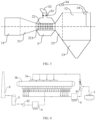
- FIG. 2 is a top view (an air branch pipe is not shown in the figure) illustrating a flue gas mixing device according to an embodiment.
- a main body of the flue gas mixing device has a venturi tube structure, and is provided with a flue entrance section 11, a necking section 21, a throat section 22, a flaring section 23 and a flue exit section 12 which are sequentially arranged along a flowing direction of flue gas.
- Air inlet holes 221 are evenly, obliquely and circumferentially arranged on a circumferential side wall of the throat section 22.
- the throat section 22 extends outwardly along a circumferential direction of the throat section 22 to form an annular cavity 3, which coats an outside of the entire throat section 22.
- An internal of the annular cavity 3 is formed with a space for accommodating gas.
- a cross-section of the annular cavity 3 may has a circular structure or a trapezoidal structure.
- the cross-section of the annular cavity 3 has a trapezoidal structure.
- a corner of the trapezoidal structure has an arc-shaped transition surface, so that there is no ash accumulation dead corner in the annular cavity 3, ensuring that the air flow entering the inside of the annular cavity 3 is unobstructed and preventing dust accumulation on an inner wall of the annular cavity 3.
- the annular cavity 3 extends outwardly to form an annular cold exhaust gas branch pipe 31, and each of the air inlet holes 221 is in communication with the annular cavity 3 and the annular cold exhaust gas branch pipe 31.
- the annular cold exhaust gas branch pipe 31 is obliquely arranged on the annular cavity 3.
- annular cold exhaust gas may enter the annular cavity 3 from the annular cold exhaust gas branch pipe 31, and then enter a flue gas main channel through the air inlet holes 221 evenly and obliquely distributed on the circumferential side wall of the throat section 22, thereby achieving a relatively uniform air intake throughout the throat section 22, buffering and stabilizing incoming flue gas, and making the annular cavity 3 and the flue gas main channel form a stable pressure difference, and maintaining a flow field of the flue gas main channel even and stable.
- the annular cavity 3 to be filled with the annular cold exhaust gas
- all the air inlet holes 221 of the throat section 22 are fully utilized to perform air intake, and the annular cold exhaust gas is accelerated when passing through the air inlet holes 221, thereby achieving the drainage effect on the incoming flue gas.
- the air inlet holes 221 on the throat section 22 are obliquely arranged, so that the annular cold exhaust gas may converge with the incoming flue gas at a predetermined angle, avoiding direct impact of the annular cold exhaust gas on the incoming flue gas, thereby reducing impact on the flow of the incoming flue gas, and reducing collision loss between introduced gas and the incoming flue gas. As shown in FIG. 3, FIG.
- FIG. 3 is a front view (an annular cold exhaust gas branch pipe is not shown in the figure) illustrating a flue gas mixing device according to an embodiment.
- An air branch pipe 32 is arranged on the annular cavity 3, and an electric valve 33 is installed at a bottom of the air branch pipe 32 to control the air branch pipe 32 to perform air intake.
- An oxygen content monitor 14 is arranged on a top of the flue exit section 12 to monitor oxygen content in the mixed flue gas in real time, and a probe of the oxygen content monitor 14 extends to a center position of the flue exit section 12 to ensure that the oxygen content of the mixed flue gas may be measured more accurately.
- the flue gas mixing device is further provided with a control assembly 34.
- the oxygen content monitor 14 is electrically connected to the control assembly 34, The oxygen content monitor 14 feeds back the detected oxygen content to the control assembly 34, and the control assembly 34 adjusts an opening degree of the electric valve 33 in the air branch pipe 32 to ensure a sufficient supply of oxygen for sintering.
- an outside of the main body of the flue gas mixing device performs thermal insulation treatment, and the opening degree of the electric valve 33 of the air branch pipe 32 is adjusted in a timely manner.
- a diameter of the flue exit section 12 is greater than a diameter of the flue entrance section 11, and an ash hopper 13 is arranged at a bottom of the flue exit section 12, so as to collect part of the dust settled by gravity due to the increase of the pipe diameter and the decrease of the flow velocity after the mixed flue gas passing through the flaring section 23, thereby effectively avoiding the ash accumulation in the flue and abrasion of the flue.
- an included angle between an axis of the air inlet holes 221 and an axis of the throat section 22 is within a range from 20° to 90°.
- An included angle between an axis of the annular cold exhaust gas branch pipe 31 and the axis of the throat section 22 is within a range from 15° to 75°.
- an included angle between an axis of the air branch pipe 32 and the axis of the throat section 22 is within a range from 30° to 90°.
- the annular cold exhaust gas branch pipe 31 is obliquely inserted into the annular cavity 3 at a certain angle, making it easier for the annular cold exhaust gas branch pipe 31 to be in communication with the annular cavity 3.
- FIG. 4 is a process flow schematic diagram illustrating a sintering flue gas circulation process according to an embodiment, and as shown in FIGS. 2 to 4 , the working principle of the sintering flue gas circulation process is as follows.
- Raw materials are sintered in a sintering machine 3b, and the sintered hot ore discharged by the sintering machine 3b is cooled by an annular cooling machine 1 and then generates annular cold exhaust gas.
- the annular cold exhaust gas and the circulating flue gas taken from a head and a tail of the sintering machine 3b and pressurized by a sintering circulation fan 41 jointly enter the flue gas mixing device, and enter the sintering machine 3b through a flue gas sealing cover 3a located on a machine head of the sintering machine 3b.
- flue gas non-circulating flue gas generated by the sintering machine 3b passes through a dust collector 4 and is sent to a desulfurization tower 5 and a chimney 6 after being pressurized by a main sintering fan 42, and is finally discharged.
- the circulating flue gas flows through the flue gas mixing device mainly formed of a classic venturi tube structure, and may generate negative pressure at the throat section 22.
- the annular cold exhaust gas is pushed by an original blower (not shown in the figure) of the annular cooling machine 1 to enter the annular cavity 3 from the annular cold exhaust gas branch pipe 31, and is sucked into the incoming flue gas in the throat section 22 via the air inlet holes 221 under the negative pressure, and the introduced annular cold exhaust gas is fully mixed with the incoming flue gad by using the pressure difference between the two fluids.
- the present embodiment may effectively realize sufficient mixing of the annular cold exhaust gas and the circulating flue gas without the annular cold circulation fan 11, and may also effectively homogenize composition and temperature of the flue gas in the sintering flue gas circulation process, and stabilize the flow rate of the flue gas.
- the air branch pipe 32 obliquely arranged on the throat section 22 may also adjust and replenish air at any time according to the change of the oxygen content in the flue exit section 12 after the mixing.
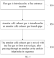
- FIG. 5 is a flowchart illustrating a flue gas mixing method according to an embodiment, and as shown in FIG. 5 , the flue gas mixing method includes steps 110 to 130.
- step 110 the flue gas is introduced to the flue entrance section.
- step 120 the annular cold exhaust gas is introduced to the annular cold exhaust gas branch pipe.
- step 130 the annular cold exhaust gas is mixed with the flue gas to form a mixed gas, after passing through the annular cavity and the air inlet holes in sequence.
- the flue gas mixing method further includes monitoring oxygen content of the mixed gas; and adjusting an amount of intake air entering the annular cavity in real time according to the oxygen content.
- the flue gas mixing device of the present disclosure solves the problems of high energy consumption and poor flue gas mixing effect of the flue gas mixing device in the related art.
Landscapes
- Engineering & Computer Science (AREA)
- Chemical & Material Sciences (AREA)
- Chemical Kinetics & Catalysis (AREA)
- Mechanical Engineering (AREA)
- General Engineering & Computer Science (AREA)
- Environmental & Geological Engineering (AREA)
- Treating Waste Gases (AREA)
- Waste-Gas Treatment And Other Accessory Devices For Furnaces (AREA)
Description
- The present disclosure relates to the technical field of gas mixing, for example, a flue gas mixing device and method.
- The sintering flue gas circulation process refers to a sintering method in which a part of the heat carrier gas discharged from a sintering process is circulated to the trolley to use after the sintering igniter. In the related technology, the sintering flue gas circulation process has proposed that in order to ensure quality of the sintered minerals during the flue gas circulation, it is necessary to ensure that the circulating flue gas contains sufficient oxygen. Therefore, in the process design, exhaust gas generated by an annular cooling machine is usually used to supplement oxygen content in the sintering flue gas.
-
FIG. 1 is a typical process flow diagram illustrating a flue gas circulation in the related art. The equipment shown inFIG. 1 includes: an annular cooling machine 1', an annular cold circulation fan 11', a flue gas mixer 2', a flue gas sealing cover 31', a sintering machine 32', a dust collector 4', a sintering circulation fan 41', a main sintering fan 42', a desulfurization tower 5 ', a chimney 6' and pipelines that connects the equipment. The working process of the sintering process, the sintering flue gas treatment process, and the flue gas circulation process are as follows. Raw materials are sintered in the sintering machine 32', and the sintered hot ore discharged by the sintering machine 32' is cooled by the annular cooling machine 1' and then generates annular cold exhaust gas. And after being pressurized by the annular cold circulation fan 11', the annular cold exhaust gas enters the flue gas mixer 2' and passes through the flue gas sealing cover 31' located above the sintering machine 32' to enter the sintering machine 32', together with the circulation flue gas taken from the sintering machine 32' and pressurized by the sintering circulation fan 41'. Most of the flue gas (non-circulating flue gas) generated by the sintering machine 32' passes through the dust collector 4' and is sent to the desulfurization tower 5 'and the chimney 6' after being pressurized by the main sintering fan 42', and is finally discharged. And the annular cold circulation fan and the flue gas mixer jointly realize the mixing of the annular cold exhaust gas and the circulating flue gas, and supplement of air is mostly realized by arranging a vent valve on the flue gas sealing cover. - At the same time, because the pressure, temperature, flow rate, composition and the like of the two flue gases to be mixed are different, the flue gas mixing device in the related art has the following problems. For example, because of the limited space of the flue and elbow thereof in a mixing device for a three-way flue, there are problems such as air flow deflection and vortexing, flue abrasion, dust accumulation and poor mixing effect, and even air flow back suction during the mixing of the two air flows, resulting in working conditions and accidents such as stall, instability and increased vibration of the flue gas circulating fan; and a mixing device with a multi-mixing cavity and a mixing device with a reducing mixing barrel may fully mix the flue gas, but neither is suitable for the flue gas with large dust content. Therefore, designing a low-resistance flue gas mixing device that may easily adjust the composition of the flue gas and the temperature of the flue gas, stabilize the flow rate of the flue gas, avoid dust accumulation in the flue and abrasion of the flue, and protect the fan and auxiliary flues and other equipment is of great significance to the stable and efficient operation of the gas circulation process.
- At the same time, in the related art, the flue gas circulation process directly supplements air from the sealing cover. Due to the large space of the sealing cover, the gas in the sealing cover will be sucked into a sintering bed to participate in the combustion reaction within a relative short residence time. Therefore, the method has the problem of uneven mixing of oxygen in the circulating flue gas, that is, the oxygen content is higher in an area adjacent to the air inlet, and the oxygen content is lower in an area far from the air inlet (also known as a hypoxic dead zone), and the hypoxic dead zone is extremely detrimental to sintering production. Therefore, it is also the key to improve the stability of the flue gas circulation process to make the oxygen carried by the supplemented air mixed evenly in the circulating flue gas by reasonable technical means. Further relevant technologies are also known from
CN105435669A , which relates to a Venturi mixer with drainage function and discloses a gas mixer according to the preamble ofclaim 1. - The present disclosure provides a flue gas mixing device and method, which may solve the problems of high energy consumption and poor flue gas mixing effect of the flue gas mixing device in the related art.
- The present invention application is set out in the appended set of claims.
- Provided is a flue gas mixing device, including:
- a flue entrance section;
- a throat section, where a plurality of air inlet holes are circumferentially arranged on a side wall of the throat section;
- an annular cavity, arranged on an outer periphery of the throat section;
- an annular cold exhaust gas branch pipe, connected to the annular cavity;
- a flue exit section;
- a necking section, connected between the flue entrance section and the throat section; and
- a flaring section, connected between the throat section and the flue exit section.
- In an embodiment, an included angle between an axis of the air inlet holes and an axis of the throat section is in a range from 20° to 90°.
- In an embodiment, an included angle between an axis of the annular cold exhaust gas branch pipe and an axis of the throat section is in a range from 15° to 75°.
- In an embodiment, a cross-section of the annular cavity has a trapezoidal structure, and a corner of the trapezoidal structure has an arc-shaped transition surface.
- The flue gas mixing device further includes an air branch pipe and a control assembly, where an included angle between an axis of the air branch pipe and an axis of the throat section is in a range from 30° to 90°; and the air branch pipe includes an electric valve being installed at a bottom of the air branch pipe to control the air branch pipe to perform air intake, and the electric valve is electrically connected to the control assembly.
- In an embodiment, the flue gas mixing device further includes an oxygen content monitor arranged on the flue exit section, where the oxygen content monitor is electrically connected to the control assembly.
- In an embodiment, the flue gas mixing device further includes an ash hopper arranged on a bottom of the flue exit section.
- In an embodiment, a diameter of the flue exit section is greater than a diameter of the flue entrance section.
- Further provided is a flue gas mixing method using the flue gas mixing device of any of
claims 1 to 7, including the following steps: the flue gas is introduced to a flue entrance section; - the annular cold exhaust gas is introduced to an annular cold exhaust gas branch pipe; and
- the annular cold exhaust gas is mixed with the flue gas to form a mixed gas, after passing through the annular cavity and the air inlet holes in sequence.
- In an embodiment, after the annular cold exhaust gas is mixed with the flue gas, the flue gas mixing method further includes monitoring oxygen content of the mixed gas, and adjusting an amount of intake air entering the annular cavity in real time according to the oxygen content.
- The flue gas mixing device and method of the present disclosure solves the problems of high energy consumption and poor flue gas mixing effect of the flue gas mixing device in the related art.
-
-
FIG. 1 is a flow schematic diagram illustrating a sintering flue gas circulation process in the related art; -
FIG. 2 is a top view illustrating a flue gas mixing device according to an embodiment; -
FIG. 3 is a front view illustrating a flue gas mixing device according to an embodiment; -
FIG. 4 is a process flow schematic diagram illustrating a sintering flue gas circulation process according to an embodiment; and -
FIG. 5 is a flowchart illustrating a flue gas mixing method according to an embodiment. - In the drawings:
- 1'-annular cooling machine; 11'-annular cold circulation fan; 2'-flue gas mixer; 31'-flue gas sealing cover; 32'-sintering machine; 4'-dust collector; 41'-sintering circulation fan; 42'-main sintering fan; 5'-desulfurization tower; 6'-chimney;
- 1-annular cooling machine; 3a-flue gas sealing cover; 3b-sintering machine; 4-dust collector;
- 41-sintering circulation fan; 42-main sintering fan; 5-desulfurization tower; 6-chimney;
- 11-flue entrance section; 12-flue exit section; 13-ash hopper; 14-oxygen content monitor;
- 21-necking section; 22-throat section; 23-flaring section; 221-air inlet hole;
- 3-annular cavity; 31-annular cold exhaust gas branch pipe; 32-air branch pipe; 33-electric valve; 34-control assembly.
- As shown in
FIG. 2, FIG. 2 is a top view (an air branch pipe is not shown in the figure) illustrating a flue gas mixing device according to an embodiment. A main body of the flue gas mixing device has a venturi tube structure, and is provided with aflue entrance section 11, anecking section 21, athroat section 22, aflaring section 23 and aflue exit section 12 which are sequentially arranged along a flowing direction of flue gas.Air inlet holes 221 are evenly, obliquely and circumferentially arranged on a circumferential side wall of thethroat section 22. Thethroat section 22 extends outwardly along a circumferential direction of thethroat section 22 to form anannular cavity 3, which coats an outside of theentire throat section 22. An internal of theannular cavity 3 is formed with a space for accommodating gas. A cross-section of theannular cavity 3 may has a circular structure or a trapezoidal structure. In one example, the cross-section of theannular cavity 3 has a trapezoidal structure. In the case that the cross-section of theannular cavity 3 has the trapezoidal structure, a corner of the trapezoidal structure has an arc-shaped transition surface, so that there is no ash accumulation dead corner in theannular cavity 3, ensuring that the air flow entering the inside of theannular cavity 3 is unobstructed and preventing dust accumulation on an inner wall of theannular cavity 3. - The
annular cavity 3 extends outwardly to form an annular cold exhaustgas branch pipe 31, and each of the air inlet holes 221 is in communication with theannular cavity 3 and the annular cold exhaustgas branch pipe 31. The annular cold exhaustgas branch pipe 31 is obliquely arranged on theannular cavity 3. By such design, annular cold exhaust gas may enter theannular cavity 3 from the annular cold exhaustgas branch pipe 31, and then enter a flue gas main channel through the air inlet holes 221 evenly and obliquely distributed on the circumferential side wall of thethroat section 22, thereby achieving a relatively uniform air intake throughout thethroat section 22, buffering and stabilizing incoming flue gas, and making theannular cavity 3 and the flue gas main channel form a stable pressure difference, and maintaining a flow field of the flue gas main channel even and stable. In one embodiment, by using theannular cavity 3 to be filled with the annular cold exhaust gas, all the air inlet holes 221 of thethroat section 22 are fully utilized to perform air intake, and the annular cold exhaust gas is accelerated when passing through the air inlet holes 221, thereby achieving the drainage effect on the incoming flue gas. In addition, the air inlet holes 221 on thethroat section 22 are obliquely arranged, so that the annular cold exhaust gas may converge with the incoming flue gas at a predetermined angle, avoiding direct impact of the annular cold exhaust gas on the incoming flue gas, thereby reducing impact on the flow of the incoming flue gas, and reducing collision loss between introduced gas and the incoming flue gas. As shown inFIG. 3, FIG. 3 is a front view (an annular cold exhaust gas branch pipe is not shown in the figure) illustrating a flue gas mixing device according to an embodiment. Anair branch pipe 32 is arranged on theannular cavity 3, and anelectric valve 33 is installed at a bottom of theair branch pipe 32 to control theair branch pipe 32 to perform air intake. An oxygen content monitor 14 is arranged on a top of theflue exit section 12 to monitor oxygen content in the mixed flue gas in real time, and a probe of the oxygen content monitor 14 extends to a center position of theflue exit section 12 to ensure that the oxygen content of the mixed flue gas may be measured more accurately. The flue gas mixing device is further provided with acontrol assembly 34. The oxygen content monitor 14 is electrically connected to thecontrol assembly 34, The oxygen content monitor 14 feeds back the detected oxygen content to thecontrol assembly 34, and thecontrol assembly 34 adjusts an opening degree of theelectric valve 33 in theair branch pipe 32 to ensure a sufficient supply of oxygen for sintering. In one embodiment, in order to reduce heat loss during the flue gas circulation process, an outside of the main body of the flue gas mixing device performs thermal insulation treatment, and the opening degree of theelectric valve 33 of theair branch pipe 32 is adjusted in a timely manner. A diameter of theflue exit section 12 is greater than a diameter of theflue entrance section 11, and anash hopper 13 is arranged at a bottom of theflue exit section 12, so as to collect part of the dust settled by gravity due to the increase of the pipe diameter and the decrease of the flow velocity after the mixed flue gas passing through theflaring section 23, thereby effectively avoiding the ash accumulation in the flue and abrasion of the flue. - As shown in
FIGS. 2 and3 , an included angle between an axis of the air inlet holes 221 and an axis of thethroat section 22 is within a range from 20° to 90°. An included angle between an axis of the annular cold exhaustgas branch pipe 31 and the axis of thethroat section 22 is within a range from 15° to 75°. And an included angle between an axis of theair branch pipe 32 and the axis of thethroat section 22 is within a range from 30° to 90°. By obliquely setting the air intake structure for the introduced gas, the direct impact of the introduced gas on the incoming flue gas may be avoided, and at the same time, drainage effect on the incoming flue gas may be performed, the uniformity and stability of the flow field of the flue gas main channel is maintained, and the collision loss between the introduced gas and the incoming flue gas is reduced. And the annular cold exhaustgas branch pipe 31 is obliquely inserted into theannular cavity 3 at a certain angle, making it easier for the annular cold exhaustgas branch pipe 31 to be in communication with theannular cavity 3. -
FIG. 4 is a process flow schematic diagram illustrating a sintering flue gas circulation process according to an embodiment, and as shown inFIGS. 2 to 4 , the working principle of the sintering flue gas circulation process is as follows. - Raw materials are sintered in a
sintering machine 3b, and the sintered hot ore discharged by thesintering machine 3b is cooled by anannular cooling machine 1 and then generates annular cold exhaust gas. And the annular cold exhaust gas and the circulating flue gas taken from a head and a tail of thesintering machine 3b and pressurized by asintering circulation fan 41 jointly enter the flue gas mixing device, and enter thesintering machine 3b through a fluegas sealing cover 3a located on a machine head of thesintering machine 3b. Most of the flue gas (non-circulating flue gas) generated by thesintering machine 3b passes through a dust collector 4 and is sent to a desulfurization tower 5 and a chimney 6 after being pressurized by amain sintering fan 42, and is finally discharged. - In the present embodiment, after being pressurized by the
sintering circulation fan 41, the circulating flue gas flows through the flue gas mixing device mainly formed of a classic venturi tube structure, and may generate negative pressure at thethroat section 22. The annular cold exhaust gas is pushed by an original blower (not shown in the figure) of theannular cooling machine 1 to enter theannular cavity 3 from the annular cold exhaustgas branch pipe 31, and is sucked into the incoming flue gas in thethroat section 22 via the air inlet holes 221 under the negative pressure, and the introduced annular cold exhaust gas is fully mixed with the incoming flue gad by using the pressure difference between the two fluids. Compared with the sintering flue gas circulation process in the related art, the present embodiment may effectively realize sufficient mixing of the annular cold exhaust gas and the circulating flue gas without the annularcold circulation fan 11, and may also effectively homogenize composition and temperature of the flue gas in the sintering flue gas circulation process, and stabilize the flow rate of the flue gas. In addition, theair branch pipe 32 obliquely arranged on thethroat section 22 may also adjust and replenish air at any time according to the change of the oxygen content in theflue exit section 12 after the mixing. -
FIG. 5 is a flowchart illustrating a flue gas mixing method according to an embodiment, and as shown inFIG. 5 , the flue gas mixing method includessteps 110 to 130. - In
step 110, the flue gas is introduced to the flue entrance section. - In
step 120, the annular cold exhaust gas is introduced to the annular cold exhaust gas branch pipe. - In
step 130, the annular cold exhaust gas is mixed with the flue gas to form a mixed gas, after passing through the annular cavity and the air inlet holes in sequence. - In one embodiment, the flue gas mixing method further includes monitoring oxygen content of the mixed gas; and adjusting an amount of intake air entering the annular cavity in real time according to the oxygen content.
- The flue gas mixing device of the present disclosure solves the problems of high energy consumption and poor flue gas mixing effect of the flue gas mixing device in the related art.
Claims (9)
- A flue gas mixing device, comprising:a flue entrance section (11);a throat section (22), wherein a plurality of air inlet holes (221) are circumferentially arranged on a side wall of the throat section (22);an annular cavity (3), arranged on an outer periphery of the throat section (22);an annular cold exhaust gas branch pipe (31), connected to the annular cavity (3);a flue exit section (12);a necking section (21), connected between the flue entrance section (11) and the throat section (22); anda flaring section (23), connected between the throat section (22) and the flue exit section (12);characterized by further comprising an air branch pipe (32) and a control assembly (34), wherein the air branch pipe (32) is arranged on the annular cavity (3), an included angle between an axis of the air branch pipe (32) and an axis of the throat section (22) is in a range from 30° to 90°; and the air branch pipe (32) comprises an electric valve (33) being installed at a bottom of the air branch pipe (32) to control the air branch pipe (32) to perform air intake, and the electric valve (33) is electrically connected to the control assembly (34).
- The flue gas mixing device of claim 1, wherein an included angle between an axis of the air inlet holes (221) and an axis of the throat section (22) is in a range from 20° to 90°.
- The flue gas mixing device of claim 1, wherein an included angle between an axis of the annular cold exhaust gas branch pipe (31) and an axis of the throat section (22) is in a range from 15° to 75°.
- The flue gas mixing device of claim 3, wherein a cross-section of the annular cavity (3) has a trapezoidal structure, and a corner of the trapezoidal structure has an arc-shaped transition surface.
- The flue gas mixing device of claim 1, further comprising an oxygen content monitor (14) arranged on the flue exit section (12), wherein the oxygen content monitor (14) is electrically connected to the control assembly (34).
- The flue gas mixing device of claim 5, further comprising an ash hopper (13) arranged at a bottom of the flue exit section (12).
- The flue gas mixing device of any one of claims 1 to 6, wherein a diameter of the flue exit section (12) is greater than a diameter of the flue entrance section (11).
- A flue gas mixing method using a flue gas mixing device of any one of claims 1 to 7, comprising:introducing flue gas to a flue entrance section (11);introducing annular cold exhaust gas to an annular cold exhaust gas branch pipe (31); andmixing the annular cold exhaust gas with the flue gas form to a mixed gas, after the annular cold exhaust gas passing through an annular cavity (3) and air inlet holes (211) in sequence.
- The flue gas mixing method of claim 8, further comprising: after the mixing the annular cold exhaust gas with the flue gas,monitoring oxygen content of the mixed gas; andadjusting an amount of intake air entering the annular cavity (3) in real time according to the oxygen content.
Applications Claiming Priority (2)
| Application Number | Priority Date | Filing Date | Title |
|---|---|---|---|
| CN201711315911.3A CN108014667B (en) | 2017-12-12 | 2017-12-12 | A flue gas mixing device and method |
| PCT/CN2018/078127 WO2019114138A1 (en) | 2017-12-12 | 2018-03-06 | Flue gas mixing device and method |
Publications (4)
| Publication Number | Publication Date |
|---|---|
| EP3666372A1 EP3666372A1 (en) | 2020-06-17 |
| EP3666372A4 EP3666372A4 (en) | 2021-10-13 |
| EP3666372B1 true EP3666372B1 (en) | 2024-08-28 |
| EP3666372C0 EP3666372C0 (en) | 2024-08-28 |
Family
ID=62072937
Family Applications (1)
| Application Number | Title | Priority Date | Filing Date |
|---|---|---|---|
| EP18889689.8A Active EP3666372B1 (en) | 2017-12-12 | 2018-03-06 | Flue gas mixing device and method |
Country Status (4)
| Country | Link |
|---|---|
| EP (1) | EP3666372B1 (en) |
| JP (1) | JP7078708B2 (en) |
| CN (1) | CN108014667B (en) |
| WO (1) | WO2019114138A1 (en) |
Families Citing this family (14)
| Publication number | Priority date | Publication date | Assignee | Title |
|---|---|---|---|---|
| CN109631032A (en) * | 2018-12-14 | 2019-04-16 | 同济大学 | A kind of cross-current flue gas air mixing device |
| CN110057197B (en) * | 2019-04-12 | 2020-05-08 | 诸暨市库仑环保科技有限公司 | A sintering flue gas waste heat circulation system |
| CN110237734A (en) * | 2019-06-10 | 2019-09-17 | 中国石油大学(北京) | Gas mixer and emission-control equipment |
| CN111960634A (en) * | 2020-08-07 | 2020-11-20 | 浙江绿治环保技术有限公司 | Jet pump steam-mud heating mixer for sludge continuous thermal hydrolysis pipeline |
| CN112461008B (en) * | 2020-11-24 | 2022-07-19 | 苏州玛旭自动化科技有限公司 | Recycling device for waste heat of tail gas of tubular furnace |
| CN112815731A (en) * | 2021-03-03 | 2021-05-18 | 焦作市迈科冶金机械有限公司 | Sintering machine hot flue gas circulation structure |
| CN113639276B (en) * | 2021-07-30 | 2022-08-16 | 西安建筑科技大学 | Anti-smoke-channeling three-way flue and control method thereof |
| CN113996155B8 (en) * | 2021-12-02 | 2024-12-31 | 宁波太极环保设备有限公司 | A smoke whitening device, chimney and smoke whitening method |
| CN114373963B (en) * | 2021-12-15 | 2024-10-11 | 国家电投集团氢能科技发展有限公司 | Humidifier and fuel cell humidified gas system |
| CN115487696B (en) * | 2022-08-26 | 2023-12-22 | 昆明有色冶金设计研究院股份公司 | Air oxygenation mixing device for micro-combustion engine |
| TWI844129B (en) * | 2022-10-04 | 2024-06-01 | 林峻梅 | Fluid temperature and flow control heating device |
| CN115751992B (en) * | 2022-12-01 | 2026-04-24 | 中冶长天国际工程有限责任公司 | A flue gas distributor |
| CN116272454B (en) * | 2023-03-14 | 2026-01-30 | 上海齐耀动力技术有限公司 | A gas mixer and a solid oxide fuel cell power generation system |
| CN119524660B (en) * | 2025-01-23 | 2025-05-09 | 西安吉利电子新材料股份有限公司 | Mixed gas equipment and method for gas |
Family Cites Families (18)
| Publication number | Priority date | Publication date | Assignee | Title |
|---|---|---|---|---|
| AT381464B (en) * | 1985-04-01 | 1986-10-27 | Waagner Biro Ag | MIXING DEVICE FOR DIFFERENT TEMPERATURE GAS FLOWS |
| FR2599437B1 (en) * | 1986-05-27 | 1990-09-21 | Roy Philippe | SHEATH INDUCING NOZZLE. |
| JPH11324812A (en) * | 1998-05-20 | 1999-11-26 | Hino Motors Ltd | Venturi type mixer |
| DE10019414C2 (en) * | 2000-04-19 | 2003-06-12 | Ballard Power Systems | Device for introducing gas into a pipe section |
| US6343594B1 (en) * | 2000-06-01 | 2002-02-05 | Caterpillar Inc. | Variable flow venturi assembly for use in an exhaust gas recirculation system of an internal combustion engine |
| US6827084B2 (en) * | 2002-06-21 | 2004-12-07 | Lloyd Thomas Grubb, Jr. | Automatic gas blender |
| US8026009B2 (en) * | 2006-10-17 | 2011-09-27 | Canon Kabushiki Kaisha | Exhaust fuel diluting mechanism and fuel cell system with the exhaust fuel diluting mechanism |
| PL2667276T3 (en) * | 2012-05-24 | 2018-04-30 | Air Products And Chemicals, Inc. | Method of, and apparatus for, providing a gas mixture |
| CN202715368U (en) * | 2012-07-20 | 2013-02-06 | 宝山钢铁股份有限公司 | Flue gas mixer |
| US9038590B2 (en) * | 2012-12-09 | 2015-05-26 | Crossroads Machine, Inc. | Adjustable venturi mixing valve assembly |
| CN203627010U (en) * | 2013-12-31 | 2014-06-04 | 广西玉柴机器股份有限公司 | EGR (Exhaust Gas Recirculation) mixer |
| CN104028133B (en) * | 2014-05-22 | 2015-11-25 | 西安交通大学 | A kind of rotatable venturi mixer |
| CN104034175B (en) * | 2014-06-11 | 2015-12-30 | 中冶北方(大连)工程技术有限公司 | A kind of energy-saving and emission-reducing sintering process |
| CN104258752B (en) * | 2014-09-30 | 2016-09-28 | 中国瑞林工程技术有限公司 | A kind of flue gas mixing arrangement and method |
| CN104748567B (en) * | 2015-03-27 | 2017-02-22 | 中国科学院过程工程研究所 | Sintering flue gas waste heat staged cyclic utilization and pollutant emission reducing process and system |
| CN205073837U (en) * | 2015-10-20 | 2016-03-09 | 秦皇岛首创思泰意达环保科技有限公司 | Flue gas washing and heat dissipation matter device |
| CN105435669A (en) * | 2015-11-23 | 2016-03-30 | 重庆普什机械有限责任公司 | Venturi mixer with drainage function |
| CN205779317U (en) * | 2016-05-06 | 2016-12-07 | 哈尔滨工程大学 | A kind of marine low speed diesel engine Venturi tube ERG of improvement |
-
2017
- 2017-12-12 CN CN201711315911.3A patent/CN108014667B/en active Active
-
2018
- 2018-03-06 EP EP18889689.8A patent/EP3666372B1/en active Active
- 2018-03-06 WO PCT/CN2018/078127 patent/WO2019114138A1/en not_active Ceased
- 2018-03-06 JP JP2020503915A patent/JP7078708B2/en active Active
Also Published As
| Publication number | Publication date |
|---|---|
| WO2019114138A1 (en) | 2019-06-20 |
| CN108014667A (en) | 2018-05-11 |
| JP2020528343A (en) | 2020-09-24 |
| EP3666372A4 (en) | 2021-10-13 |
| CN108014667B (en) | 2019-08-13 |
| EP3666372A1 (en) | 2020-06-17 |
| JP7078708B2 (en) | 2022-05-31 |
| EP3666372C0 (en) | 2024-08-28 |
Similar Documents
| Publication | Publication Date | Title |
|---|---|---|
| EP3666372A1 (en) | Flue gas mixing device and method | |
| AU2016225385A1 (en) | Apparatus and method for calcination of gypsum | |
| CN103398379A (en) | Oxygen-enriched burner | |
| TWI725736B (en) | Combustible waste blowing device and operation method thereof | |
| CN102627417A (en) | Lime cooling equipment of sleeve kiln | |
| CN209558878U (en) | Precalciner | |
| CN101468365B (en) | Air guide device and workpiece cooling device adopting the air guide device | |
| CN107300317A (en) | A kind of method of huge revolving kiln system and its calcined diatomite | |
| CN203628653U (en) | Oxygen-enriched burner | |
| CN104561586B (en) | Concentrate nozzle of flash smelting furnace | |
| TWI721782B (en) | Combustible waste blowing device and operation method thereof | |
| CN209085290U (en) | A kind of powder metallurgy sintered hardening sintering furnace of stator production | |
| CN209388781U (en) | A kind of horizontal enameling machine | |
| CN106766153B (en) | Multi-jet hole type hot blast stove | |
| CN206786755U (en) | Spiral-flow type attemperating air duct and high-temperature flue cooling system | |
| CN202048570U (en) | Wide-range temperature adjustment burner | |
| CN104561587B (en) | Concentrate jet nozzle of smelting furnace | |
| CN218864750U (en) | Precisely controlled quenching and tempering furnace for roasting rotary kiln | |
| CN208800681U (en) | Roller-bottom type aluminum alloy heat forming furnace | |
| CN206682926U (en) | Five-channel coal-powder combustor | |
| CN1279191C (en) | Shaft furnace internal heat control method and internal-combustion pelletizing shaft furnace realizing same | |
| CN217559843U (en) | CO waste gas treatment system | |
| CN212179210U (en) | Energy-saving hot-blast stove | |
| CN211999790U (en) | Cyclone air blast furnace coal powder belly pipe | |
| CN205860744U (en) | The increasing wind pressurizer of rotary kiln drying system |
Legal Events
| Date | Code | Title | Description |
|---|---|---|---|
| STAA | Information on the status of an ep patent application or granted ep patent |
Free format text: STATUS: THE INTERNATIONAL PUBLICATION HAS BEEN MADE |
|
| PUAI | Public reference made under article 153(3) epc to a published international application that has entered the european phase |
Free format text: ORIGINAL CODE: 0009012 |
|
| STAA | Information on the status of an ep patent application or granted ep patent |
Free format text: STATUS: REQUEST FOR EXAMINATION WAS MADE |
|
| 17P | Request for examination filed |
Effective date: 20200312 |
|
| AK | Designated contracting states |
Kind code of ref document: A1 Designated state(s): AL AT BE BG CH CY CZ DE DK EE ES FI FR GB GR HR HU IE IS IT LI LT LU LV MC MK MT NL NO PL PT RO RS SE SI SK SM TR |
|
| AX | Request for extension of the european patent |
Extension state: BA ME |
|
| DAV | Request for validation of the european patent (deleted) | ||
| DAX | Request for extension of the european patent (deleted) | ||
| RIC1 | Information provided on ipc code assigned before grant |
Ipc: B01F 3/02 20060101AFI20210511BHEP Ipc: B01F 5/04 20060101ALI20210511BHEP Ipc: B01F 15/00 20060101ALI20210511BHEP Ipc: F27D 17/00 20060101ALI20210511BHEP |
|
| REG | Reference to a national code |
Ref country code: DE Ref legal event code: R079 Free format text: PREVIOUS MAIN CLASS: B01F0005040000 Ipc: B01F0003020000 Ref country code: DE Ref legal event code: R079 Ref document number: 602018073795 Country of ref document: DE Free format text: PREVIOUS MAIN CLASS: B01F0005040000 Ipc: B01F0003020000 |
|
| A4 | Supplementary search report drawn up and despatched |
Effective date: 20210913 |
|
| RIC1 | Information provided on ipc code assigned before grant |
Ipc: F27D 17/00 20060101ALI20210907BHEP Ipc: F27B 21/00 20060101ALI20210907BHEP Ipc: B01F 15/00 20060101ALI20210907BHEP Ipc: B01F 5/04 20060101ALI20210907BHEP Ipc: B01F 3/02 20060101AFI20210907BHEP |
|
| STAA | Information on the status of an ep patent application or granted ep patent |
Free format text: STATUS: EXAMINATION IS IN PROGRESS |
|
| 17Q | First examination report despatched |
Effective date: 20230126 |
|
| REG | Reference to a national code |
Ref country code: DE Ref legal event code: R079 Free format text: PREVIOUS MAIN CLASS: B01F0003020000 Ipc: B01F0023100000 Ref document number: 602018073795 Country of ref document: DE |
|
| GRAP | Despatch of communication of intention to grant a patent |
Free format text: ORIGINAL CODE: EPIDOSNIGR1 |
|
| STAA | Information on the status of an ep patent application or granted ep patent |
Free format text: STATUS: GRANT OF PATENT IS INTENDED |
|
| RIC1 | Information provided on ipc code assigned before grant |
Ipc: F27D 17/00 20060101ALI20240605BHEP Ipc: F27B 21/00 20060101ALI20240605BHEP Ipc: B01F 35/22 20220101ALI20240605BHEP Ipc: B01F 35/21 20220101ALI20240605BHEP Ipc: B01F 25/314 20220101ALI20240605BHEP Ipc: B01F 25/312 20220101ALI20240605BHEP Ipc: B01F 23/10 20220101AFI20240605BHEP |
|
| GRAS | Grant fee paid |
Free format text: ORIGINAL CODE: EPIDOSNIGR3 |
|
| INTG | Intention to grant announced |
Effective date: 20240625 |
|
| GRAA | (expected) grant |
Free format text: ORIGINAL CODE: 0009210 |
|
| STAA | Information on the status of an ep patent application or granted ep patent |
Free format text: STATUS: THE PATENT HAS BEEN GRANTED |
|
| AK | Designated contracting states |
Kind code of ref document: B1 Designated state(s): AL AT BE BG CH CY CZ DE DK EE ES FI FR GB GR HR HU IE IS IT LI LT LU LV MC MK MT NL NO PL PT RO RS SE SI SK SM TR |
|
| REG | Reference to a national code |
Ref country code: GB Ref legal event code: FG4D |
|
| REG | Reference to a national code |
Ref country code: CH Ref legal event code: EP |
|
| REG | Reference to a national code |
Ref country code: DE Ref legal event code: R096 Ref document number: 602018073795 Country of ref document: DE |
|
| REG | Reference to a national code |
Ref country code: IE Ref legal event code: FG4D |
|
| U01 | Request for unitary effect filed |
Effective date: 20240924 |
|
| U07 | Unitary effect registered |
Designated state(s): AT BE BG DE DK EE FI FR IT LT LU LV MT NL PT RO SE SI Effective date: 20241016 |
|
| PG25 | Lapsed in a contracting state [announced via postgrant information from national office to epo] |
Ref country code: NO Free format text: LAPSE BECAUSE OF FAILURE TO SUBMIT A TRANSLATION OF THE DESCRIPTION OR TO PAY THE FEE WITHIN THE PRESCRIBED TIME-LIMIT Effective date: 20241128 |
|
| PG25 | Lapsed in a contracting state [announced via postgrant information from national office to epo] |
Ref country code: GR Free format text: LAPSE BECAUSE OF FAILURE TO SUBMIT A TRANSLATION OF THE DESCRIPTION OR TO PAY THE FEE WITHIN THE PRESCRIBED TIME-LIMIT Effective date: 20241129 Ref country code: PL Free format text: LAPSE BECAUSE OF FAILURE TO SUBMIT A TRANSLATION OF THE DESCRIPTION OR TO PAY THE FEE WITHIN THE PRESCRIBED TIME-LIMIT Effective date: 20240828 |
|
| PG25 | Lapsed in a contracting state [announced via postgrant information from national office to epo] |
Ref country code: IS Free format text: LAPSE BECAUSE OF FAILURE TO SUBMIT A TRANSLATION OF THE DESCRIPTION OR TO PAY THE FEE WITHIN THE PRESCRIBED TIME-LIMIT Effective date: 20241228 |
|
| PG25 | Lapsed in a contracting state [announced via postgrant information from national office to epo] |
Ref country code: HR Free format text: LAPSE BECAUSE OF FAILURE TO SUBMIT A TRANSLATION OF THE DESCRIPTION OR TO PAY THE FEE WITHIN THE PRESCRIBED TIME-LIMIT Effective date: 20240828 |
|
| PG25 | Lapsed in a contracting state [announced via postgrant information from national office to epo] |
Ref country code: ES Free format text: LAPSE BECAUSE OF FAILURE TO SUBMIT A TRANSLATION OF THE DESCRIPTION OR TO PAY THE FEE WITHIN THE PRESCRIBED TIME-LIMIT Effective date: 20240828 Ref country code: RS Free format text: LAPSE BECAUSE OF FAILURE TO SUBMIT A TRANSLATION OF THE DESCRIPTION OR TO PAY THE FEE WITHIN THE PRESCRIBED TIME-LIMIT Effective date: 20241128 |
|
| PG25 | Lapsed in a contracting state [announced via postgrant information from national office to epo] |
Ref country code: RS Free format text: LAPSE BECAUSE OF FAILURE TO SUBMIT A TRANSLATION OF THE DESCRIPTION OR TO PAY THE FEE WITHIN THE PRESCRIBED TIME-LIMIT Effective date: 20241128 Ref country code: PL Free format text: LAPSE BECAUSE OF FAILURE TO SUBMIT A TRANSLATION OF THE DESCRIPTION OR TO PAY THE FEE WITHIN THE PRESCRIBED TIME-LIMIT Effective date: 20240828 Ref country code: NO Free format text: LAPSE BECAUSE OF FAILURE TO SUBMIT A TRANSLATION OF THE DESCRIPTION OR TO PAY THE FEE WITHIN THE PRESCRIBED TIME-LIMIT Effective date: 20241128 Ref country code: IS Free format text: LAPSE BECAUSE OF FAILURE TO SUBMIT A TRANSLATION OF THE DESCRIPTION OR TO PAY THE FEE WITHIN THE PRESCRIBED TIME-LIMIT Effective date: 20241228 Ref country code: HR Free format text: LAPSE BECAUSE OF FAILURE TO SUBMIT A TRANSLATION OF THE DESCRIPTION OR TO PAY THE FEE WITHIN THE PRESCRIBED TIME-LIMIT Effective date: 20240828 Ref country code: GR Free format text: LAPSE BECAUSE OF FAILURE TO SUBMIT A TRANSLATION OF THE DESCRIPTION OR TO PAY THE FEE WITHIN THE PRESCRIBED TIME-LIMIT Effective date: 20241129 Ref country code: ES Free format text: LAPSE BECAUSE OF FAILURE TO SUBMIT A TRANSLATION OF THE DESCRIPTION OR TO PAY THE FEE WITHIN THE PRESCRIBED TIME-LIMIT Effective date: 20240828 |
|
| PG25 | Lapsed in a contracting state [announced via postgrant information from national office to epo] |
Ref country code: SM Free format text: LAPSE BECAUSE OF FAILURE TO SUBMIT A TRANSLATION OF THE DESCRIPTION OR TO PAY THE FEE WITHIN THE PRESCRIBED TIME-LIMIT Effective date: 20240828 |
|
| PG25 | Lapsed in a contracting state [announced via postgrant information from national office to epo] |
Ref country code: CZ Free format text: LAPSE BECAUSE OF FAILURE TO SUBMIT A TRANSLATION OF THE DESCRIPTION OR TO PAY THE FEE WITHIN THE PRESCRIBED TIME-LIMIT Effective date: 20240828 |
|
| PG25 | Lapsed in a contracting state [announced via postgrant information from national office to epo] |
Ref country code: SK Free format text: LAPSE BECAUSE OF FAILURE TO SUBMIT A TRANSLATION OF THE DESCRIPTION OR TO PAY THE FEE WITHIN THE PRESCRIBED TIME-LIMIT Effective date: 20240828 |
|
| U20 | Renewal fee for the european patent with unitary effect paid |
Year of fee payment: 8 Effective date: 20250325 |
|
| PLBE | No opposition filed within time limit |
Free format text: ORIGINAL CODE: 0009261 |
|
| STAA | Information on the status of an ep patent application or granted ep patent |
Free format text: STATUS: NO OPPOSITION FILED WITHIN TIME LIMIT |
|
| 26N | No opposition filed |
Effective date: 20250530 |
|
| PG25 | Lapsed in a contracting state [announced via postgrant information from national office to epo] |
Ref country code: MC Free format text: LAPSE BECAUSE OF FAILURE TO SUBMIT A TRANSLATION OF THE DESCRIPTION OR TO PAY THE FEE WITHIN THE PRESCRIBED TIME-LIMIT Effective date: 20240828 |
|
| REG | Reference to a national code |
Ref country code: CH Ref legal event code: H13 Free format text: ST27 STATUS EVENT CODE: U-0-0-H10-H13 (AS PROVIDED BY THE NATIONAL OFFICE) Effective date: 20251023 |
|
| GBPC | Gb: european patent ceased through non-payment of renewal fee |
Effective date: 20250306 |
|
| PG25 | Lapsed in a contracting state [announced via postgrant information from national office to epo] |
Ref country code: GB Free format text: LAPSE BECAUSE OF NON-PAYMENT OF DUE FEES Effective date: 20250306 |
|
| PG25 | Lapsed in a contracting state [announced via postgrant information from national office to epo] |
Ref country code: CH Free format text: LAPSE BECAUSE OF NON-PAYMENT OF DUE FEES Effective date: 20250331 |
|
| PG25 | Lapsed in a contracting state [announced via postgrant information from national office to epo] |
Ref country code: IE Free format text: LAPSE BECAUSE OF NON-PAYMENT OF DUE FEES Effective date: 20250306 |
|
| U20 | Renewal fee for the european patent with unitary effect paid |
Year of fee payment: 9 Effective date: 20260327 |