EP3665029B1 - Virtual human-machine interface system and corresponding virtual human-machine interface method for a vehicle - Google Patents
Virtual human-machine interface system and corresponding virtual human-machine interface method for a vehicle Download PDFInfo
- Publication number
- EP3665029B1 EP3665029B1 EP18759754.7A EP18759754A EP3665029B1 EP 3665029 B1 EP3665029 B1 EP 3665029B1 EP 18759754 A EP18759754 A EP 18759754A EP 3665029 B1 EP3665029 B1 EP 3665029B1
- Authority
- EP
- European Patent Office
- Prior art keywords
- projection surface
- user
- machine interface
- vehicle
- projection
- Prior art date
- Legal status (The legal status is an assumption and is not a legal conclusion. Google has not performed a legal analysis and makes no representation as to the accuracy of the status listed.)
- Active
Links
Images


Classifications
-
- B—PERFORMING OPERATIONS; TRANSPORTING
- B60—VEHICLES IN GENERAL
- B60K—ARRANGEMENT OR MOUNTING OF PROPULSION UNITS OR OF TRANSMISSIONS IN VEHICLES; ARRANGEMENT OR MOUNTING OF PLURAL DIVERSE PRIME-MOVERS IN VEHICLES; AUXILIARY DRIVES FOR VEHICLES; INSTRUMENTATION OR DASHBOARDS FOR VEHICLES; ARRANGEMENTS IN CONNECTION WITH COOLING, AIR INTAKE, GAS EXHAUST OR FUEL SUPPLY OF PROPULSION UNITS IN VEHICLES
- B60K35/00—Instruments specially adapted for vehicles; Arrangement of instruments in or on vehicles
- B60K35/10—Input arrangements, i.e. from user to vehicle, associated with vehicle functions or specially adapted therefor
-
- B—PERFORMING OPERATIONS; TRANSPORTING
- B60—VEHICLES IN GENERAL
- B60K—ARRANGEMENT OR MOUNTING OF PROPULSION UNITS OR OF TRANSMISSIONS IN VEHICLES; ARRANGEMENT OR MOUNTING OF PLURAL DIVERSE PRIME-MOVERS IN VEHICLES; AUXILIARY DRIVES FOR VEHICLES; INSTRUMENTATION OR DASHBOARDS FOR VEHICLES; ARRANGEMENTS IN CONNECTION WITH COOLING, AIR INTAKE, GAS EXHAUST OR FUEL SUPPLY OF PROPULSION UNITS IN VEHICLES
- B60K35/00—Instruments specially adapted for vehicles; Arrangement of instruments in or on vehicles
- B60K35/20—Output arrangements, i.e. from vehicle to user, associated with vehicle functions or specially adapted therefor
-
- B—PERFORMING OPERATIONS; TRANSPORTING
- B60—VEHICLES IN GENERAL
- B60K—ARRANGEMENT OR MOUNTING OF PROPULSION UNITS OR OF TRANSMISSIONS IN VEHICLES; ARRANGEMENT OR MOUNTING OF PLURAL DIVERSE PRIME-MOVERS IN VEHICLES; AUXILIARY DRIVES FOR VEHICLES; INSTRUMENTATION OR DASHBOARDS FOR VEHICLES; ARRANGEMENTS IN CONNECTION WITH COOLING, AIR INTAKE, GAS EXHAUST OR FUEL SUPPLY OF PROPULSION UNITS IN VEHICLES
- B60K35/00—Instruments specially adapted for vehicles; Arrangement of instruments in or on vehicles
- B60K35/20—Output arrangements, i.e. from vehicle to user, associated with vehicle functions or specially adapted therefor
- B60K35/21—Output arrangements, i.e. from vehicle to user, associated with vehicle functions or specially adapted therefor using visual output, e.g. blinking lights or matrix displays
- B60K35/213—Virtual instruments
-
- B—PERFORMING OPERATIONS; TRANSPORTING
- B60—VEHICLES IN GENERAL
- B60K—ARRANGEMENT OR MOUNTING OF PROPULSION UNITS OR OF TRANSMISSIONS IN VEHICLES; ARRANGEMENT OR MOUNTING OF PLURAL DIVERSE PRIME-MOVERS IN VEHICLES; AUXILIARY DRIVES FOR VEHICLES; INSTRUMENTATION OR DASHBOARDS FOR VEHICLES; ARRANGEMENTS IN CONNECTION WITH COOLING, AIR INTAKE, GAS EXHAUST OR FUEL SUPPLY OF PROPULSION UNITS IN VEHICLES
- B60K35/00—Instruments specially adapted for vehicles; Arrangement of instruments in or on vehicles
- B60K35/20—Output arrangements, i.e. from vehicle to user, associated with vehicle functions or specially adapted therefor
- B60K35/21—Output arrangements, i.e. from vehicle to user, associated with vehicle functions or specially adapted therefor using visual output, e.g. blinking lights or matrix displays
- B60K35/22—Display screens
-
- B—PERFORMING OPERATIONS; TRANSPORTING
- B60—VEHICLES IN GENERAL
- B60K—ARRANGEMENT OR MOUNTING OF PROPULSION UNITS OR OF TRANSMISSIONS IN VEHICLES; ARRANGEMENT OR MOUNTING OF PLURAL DIVERSE PRIME-MOVERS IN VEHICLES; AUXILIARY DRIVES FOR VEHICLES; INSTRUMENTATION OR DASHBOARDS FOR VEHICLES; ARRANGEMENTS IN CONNECTION WITH COOLING, AIR INTAKE, GAS EXHAUST OR FUEL SUPPLY OF PROPULSION UNITS IN VEHICLES
- B60K35/00—Instruments specially adapted for vehicles; Arrangement of instruments in or on vehicles
- B60K35/20—Output arrangements, i.e. from vehicle to user, associated with vehicle functions or specially adapted therefor
- B60K35/29—Instruments characterised by the way in which information is handled, e.g. showing information on plural displays or prioritising information according to driving conditions
-
- B—PERFORMING OPERATIONS; TRANSPORTING
- B60—VEHICLES IN GENERAL
- B60K—ARRANGEMENT OR MOUNTING OF PROPULSION UNITS OR OF TRANSMISSIONS IN VEHICLES; ARRANGEMENT OR MOUNTING OF PLURAL DIVERSE PRIME-MOVERS IN VEHICLES; AUXILIARY DRIVES FOR VEHICLES; INSTRUMENTATION OR DASHBOARDS FOR VEHICLES; ARRANGEMENTS IN CONNECTION WITH COOLING, AIR INTAKE, GAS EXHAUST OR FUEL SUPPLY OF PROPULSION UNITS IN VEHICLES
- B60K35/00—Instruments specially adapted for vehicles; Arrangement of instruments in or on vehicles
- B60K35/60—Instruments characterised by their location or relative disposition in or on vehicles
-
- B—PERFORMING OPERATIONS; TRANSPORTING
- B60—VEHICLES IN GENERAL
- B60K—ARRANGEMENT OR MOUNTING OF PROPULSION UNITS OR OF TRANSMISSIONS IN VEHICLES; ARRANGEMENT OR MOUNTING OF PLURAL DIVERSE PRIME-MOVERS IN VEHICLES; AUXILIARY DRIVES FOR VEHICLES; INSTRUMENTATION OR DASHBOARDS FOR VEHICLES; ARRANGEMENTS IN CONNECTION WITH COOLING, AIR INTAKE, GAS EXHAUST OR FUEL SUPPLY OF PROPULSION UNITS IN VEHICLES
- B60K35/00—Instruments specially adapted for vehicles; Arrangement of instruments in or on vehicles
- B60K35/65—Instruments specially adapted for specific vehicle types or users, e.g. for left- or right-hand drive
- B60K35/654—Instruments specially adapted for specific vehicle types or users, e.g. for left- or right-hand drive the user being the driver
-
- B—PERFORMING OPERATIONS; TRANSPORTING
- B60—VEHICLES IN GENERAL
- B60K—ARRANGEMENT OR MOUNTING OF PROPULSION UNITS OR OF TRANSMISSIONS IN VEHICLES; ARRANGEMENT OR MOUNTING OF PLURAL DIVERSE PRIME-MOVERS IN VEHICLES; AUXILIARY DRIVES FOR VEHICLES; INSTRUMENTATION OR DASHBOARDS FOR VEHICLES; ARRANGEMENTS IN CONNECTION WITH COOLING, AIR INTAKE, GAS EXHAUST OR FUEL SUPPLY OF PROPULSION UNITS IN VEHICLES
- B60K35/00—Instruments specially adapted for vehicles; Arrangement of instruments in or on vehicles
- B60K35/65—Instruments specially adapted for specific vehicle types or users, e.g. for left- or right-hand drive
- B60K35/658—Instruments specially adapted for specific vehicle types or users, e.g. for left- or right-hand drive the instruments being ergonomically adjustable to the user
-
- B—PERFORMING OPERATIONS; TRANSPORTING
- B60—VEHICLES IN GENERAL
- B60K—ARRANGEMENT OR MOUNTING OF PROPULSION UNITS OR OF TRANSMISSIONS IN VEHICLES; ARRANGEMENT OR MOUNTING OF PLURAL DIVERSE PRIME-MOVERS IN VEHICLES; AUXILIARY DRIVES FOR VEHICLES; INSTRUMENTATION OR DASHBOARDS FOR VEHICLES; ARRANGEMENTS IN CONNECTION WITH COOLING, AIR INTAKE, GAS EXHAUST OR FUEL SUPPLY OF PROPULSION UNITS IN VEHICLES
- B60K35/00—Instruments specially adapted for vehicles; Arrangement of instruments in or on vehicles
- B60K35/80—Arrangements for controlling instruments
-
- B—PERFORMING OPERATIONS; TRANSPORTING
- B60—VEHICLES IN GENERAL
- B60K—ARRANGEMENT OR MOUNTING OF PROPULSION UNITS OR OF TRANSMISSIONS IN VEHICLES; ARRANGEMENT OR MOUNTING OF PLURAL DIVERSE PRIME-MOVERS IN VEHICLES; AUXILIARY DRIVES FOR VEHICLES; INSTRUMENTATION OR DASHBOARDS FOR VEHICLES; ARRANGEMENTS IN CONNECTION WITH COOLING, AIR INTAKE, GAS EXHAUST OR FUEL SUPPLY OF PROPULSION UNITS IN VEHICLES
- B60K35/00—Instruments specially adapted for vehicles; Arrangement of instruments in or on vehicles
- B60K35/80—Arrangements for controlling instruments
- B60K35/81—Arrangements for controlling instruments for controlling displays
-
- G—PHYSICS
- G06—COMPUTING OR CALCULATING; COUNTING
- G06F—ELECTRIC DIGITAL DATA PROCESSING
- G06F3/00—Input arrangements for transferring data to be processed into a form capable of being handled by the computer; Output arrangements for transferring data from processing unit to output unit, e.g. interface arrangements
- G06F3/01—Input arrangements or combined input and output arrangements for interaction between user and computer
- G06F3/011—Arrangements for interaction with the human body, e.g. for user immersion in virtual reality
-
- G—PHYSICS
- G06—COMPUTING OR CALCULATING; COUNTING
- G06F—ELECTRIC DIGITAL DATA PROCESSING
- G06F3/00—Input arrangements for transferring data to be processed into a form capable of being handled by the computer; Output arrangements for transferring data from processing unit to output unit, e.g. interface arrangements
- G06F3/01—Input arrangements or combined input and output arrangements for interaction between user and computer
- G06F3/03—Arrangements for converting the position or the displacement of a member into a coded form
- G06F3/041—Digitisers, e.g. for touch screens or touch pads, characterised by the transducing means
- G06F3/042—Digitisers, e.g. for touch screens or touch pads, characterised by the transducing means by opto-electronic means
- G06F3/0425—Digitisers, e.g. for touch screens or touch pads, characterised by the transducing means by opto-electronic means using a single imaging device like a video camera for tracking the absolute position of a single or a plurality of objects with respect to an imaged reference surface, e.g. video camera imaging a display or a projection screen, a table or a wall surface, on which a computer generated image is displayed or projected
-
- G—PHYSICS
- G06—COMPUTING OR CALCULATING; COUNTING
- G06F—ELECTRIC DIGITAL DATA PROCESSING
- G06F3/00—Input arrangements for transferring data to be processed into a form capable of being handled by the computer; Output arrangements for transferring data from processing unit to output unit, e.g. interface arrangements
- G06F3/01—Input arrangements or combined input and output arrangements for interaction between user and computer
- G06F3/048—Interaction techniques based on graphical user interfaces [GUI]
- G06F3/0484—Interaction techniques based on graphical user interfaces [GUI] for the control of specific functions or operations, e.g. selecting or manipulating an object, an image or a displayed text element, setting a parameter value or selecting a range
- G06F3/04845—Interaction techniques based on graphical user interfaces [GUI] for the control of specific functions or operations, e.g. selecting or manipulating an object, an image or a displayed text element, setting a parameter value or selecting a range for image manipulation, e.g. dragging, rotation, expansion or change of colour
-
- B—PERFORMING OPERATIONS; TRANSPORTING
- B60—VEHICLES IN GENERAL
- B60K—ARRANGEMENT OR MOUNTING OF PROPULSION UNITS OR OF TRANSMISSIONS IN VEHICLES; ARRANGEMENT OR MOUNTING OF PLURAL DIVERSE PRIME-MOVERS IN VEHICLES; AUXILIARY DRIVES FOR VEHICLES; INSTRUMENTATION OR DASHBOARDS FOR VEHICLES; ARRANGEMENTS IN CONNECTION WITH COOLING, AIR INTAKE, GAS EXHAUST OR FUEL SUPPLY OF PROPULSION UNITS IN VEHICLES
- B60K2360/00—Indexing scheme associated with groups B60K35/00 or B60K37/00 relating to details of instruments or dashboards
- B60K2360/11—Instrument graphical user interfaces or menu aspects
-
- B—PERFORMING OPERATIONS; TRANSPORTING
- B60—VEHICLES IN GENERAL
- B60K—ARRANGEMENT OR MOUNTING OF PROPULSION UNITS OR OF TRANSMISSIONS IN VEHICLES; ARRANGEMENT OR MOUNTING OF PLURAL DIVERSE PRIME-MOVERS IN VEHICLES; AUXILIARY DRIVES FOR VEHICLES; INSTRUMENTATION OR DASHBOARDS FOR VEHICLES; ARRANGEMENTS IN CONNECTION WITH COOLING, AIR INTAKE, GAS EXHAUST OR FUEL SUPPLY OF PROPULSION UNITS IN VEHICLES
- B60K2360/00—Indexing scheme associated with groups B60K35/00 or B60K37/00 relating to details of instruments or dashboards
- B60K2360/143—Touch sensitive instrument input devices
-
- B—PERFORMING OPERATIONS; TRANSPORTING
- B60—VEHICLES IN GENERAL
- B60K—ARRANGEMENT OR MOUNTING OF PROPULSION UNITS OR OF TRANSMISSIONS IN VEHICLES; ARRANGEMENT OR MOUNTING OF PLURAL DIVERSE PRIME-MOVERS IN VEHICLES; AUXILIARY DRIVES FOR VEHICLES; INSTRUMENTATION OR DASHBOARDS FOR VEHICLES; ARRANGEMENTS IN CONNECTION WITH COOLING, AIR INTAKE, GAS EXHAUST OR FUEL SUPPLY OF PROPULSION UNITS IN VEHICLES
- B60K2360/00—Indexing scheme associated with groups B60K35/00 or B60K37/00 relating to details of instruments or dashboards
- B60K2360/146—Instrument input by gesture
-
- B—PERFORMING OPERATIONS; TRANSPORTING
- B60—VEHICLES IN GENERAL
- B60K—ARRANGEMENT OR MOUNTING OF PROPULSION UNITS OR OF TRANSMISSIONS IN VEHICLES; ARRANGEMENT OR MOUNTING OF PLURAL DIVERSE PRIME-MOVERS IN VEHICLES; AUXILIARY DRIVES FOR VEHICLES; INSTRUMENTATION OR DASHBOARDS FOR VEHICLES; ARRANGEMENTS IN CONNECTION WITH COOLING, AIR INTAKE, GAS EXHAUST OR FUEL SUPPLY OF PROPULSION UNITS IN VEHICLES
- B60K2360/00—Indexing scheme associated with groups B60K35/00 or B60K37/00 relating to details of instruments or dashboards
- B60K2360/146—Instrument input by gesture
- B60K2360/1468—Touch gesture
-
- B—PERFORMING OPERATIONS; TRANSPORTING
- B60—VEHICLES IN GENERAL
- B60K—ARRANGEMENT OR MOUNTING OF PROPULSION UNITS OR OF TRANSMISSIONS IN VEHICLES; ARRANGEMENT OR MOUNTING OF PLURAL DIVERSE PRIME-MOVERS IN VEHICLES; AUXILIARY DRIVES FOR VEHICLES; INSTRUMENTATION OR DASHBOARDS FOR VEHICLES; ARRANGEMENTS IN CONNECTION WITH COOLING, AIR INTAKE, GAS EXHAUST OR FUEL SUPPLY OF PROPULSION UNITS IN VEHICLES
- B60K2360/00—Indexing scheme associated with groups B60K35/00 or B60K37/00 relating to details of instruments or dashboards
- B60K2360/146—Instrument input by gesture
- B60K2360/1468—Touch gesture
- B60K2360/1472—Multi-touch gesture
-
- B—PERFORMING OPERATIONS; TRANSPORTING
- B60—VEHICLES IN GENERAL
- B60K—ARRANGEMENT OR MOUNTING OF PROPULSION UNITS OR OF TRANSMISSIONS IN VEHICLES; ARRANGEMENT OR MOUNTING OF PLURAL DIVERSE PRIME-MOVERS IN VEHICLES; AUXILIARY DRIVES FOR VEHICLES; INSTRUMENTATION OR DASHBOARDS FOR VEHICLES; ARRANGEMENTS IN CONNECTION WITH COOLING, AIR INTAKE, GAS EXHAUST OR FUEL SUPPLY OF PROPULSION UNITS IN VEHICLES
- B60K2360/00—Indexing scheme associated with groups B60K35/00 or B60K37/00 relating to details of instruments or dashboards
- B60K2360/151—Instrument output devices for configurable output
-
- B—PERFORMING OPERATIONS; TRANSPORTING
- B60—VEHICLES IN GENERAL
- B60K—ARRANGEMENT OR MOUNTING OF PROPULSION UNITS OR OF TRANSMISSIONS IN VEHICLES; ARRANGEMENT OR MOUNTING OF PLURAL DIVERSE PRIME-MOVERS IN VEHICLES; AUXILIARY DRIVES FOR VEHICLES; INSTRUMENTATION OR DASHBOARDS FOR VEHICLES; ARRANGEMENTS IN CONNECTION WITH COOLING, AIR INTAKE, GAS EXHAUST OR FUEL SUPPLY OF PROPULSION UNITS IN VEHICLES
- B60K2360/00—Indexing scheme associated with groups B60K35/00 or B60K37/00 relating to details of instruments or dashboards
- B60K2360/18—Information management
- B60K2360/182—Distributing information between displays
-
- B—PERFORMING OPERATIONS; TRANSPORTING
- B60—VEHICLES IN GENERAL
- B60K—ARRANGEMENT OR MOUNTING OF PROPULSION UNITS OR OF TRANSMISSIONS IN VEHICLES; ARRANGEMENT OR MOUNTING OF PLURAL DIVERSE PRIME-MOVERS IN VEHICLES; AUXILIARY DRIVES FOR VEHICLES; INSTRUMENTATION OR DASHBOARDS FOR VEHICLES; ARRANGEMENTS IN CONNECTION WITH COOLING, AIR INTAKE, GAS EXHAUST OR FUEL SUPPLY OF PROPULSION UNITS IN VEHICLES
- B60K2360/00—Indexing scheme associated with groups B60K35/00 or B60K37/00 relating to details of instruments or dashboards
- B60K2360/20—Optical features of instruments
- B60K2360/23—Optical features of instruments using reflectors
-
- B—PERFORMING OPERATIONS; TRANSPORTING
- B60—VEHICLES IN GENERAL
- B60K—ARRANGEMENT OR MOUNTING OF PROPULSION UNITS OR OF TRANSMISSIONS IN VEHICLES; ARRANGEMENT OR MOUNTING OF PLURAL DIVERSE PRIME-MOVERS IN VEHICLES; AUXILIARY DRIVES FOR VEHICLES; INSTRUMENTATION OR DASHBOARDS FOR VEHICLES; ARRANGEMENTS IN CONNECTION WITH COOLING, AIR INTAKE, GAS EXHAUST OR FUEL SUPPLY OF PROPULSION UNITS IN VEHICLES
- B60K2360/00—Indexing scheme associated with groups B60K35/00 or B60K37/00 relating to details of instruments or dashboards
- B60K2360/20—Optical features of instruments
- B60K2360/29—Holographic features
-
- B—PERFORMING OPERATIONS; TRANSPORTING
- B60—VEHICLES IN GENERAL
- B60K—ARRANGEMENT OR MOUNTING OF PROPULSION UNITS OR OF TRANSMISSIONS IN VEHICLES; ARRANGEMENT OR MOUNTING OF PLURAL DIVERSE PRIME-MOVERS IN VEHICLES; AUXILIARY DRIVES FOR VEHICLES; INSTRUMENTATION OR DASHBOARDS FOR VEHICLES; ARRANGEMENTS IN CONNECTION WITH COOLING, AIR INTAKE, GAS EXHAUST OR FUEL SUPPLY OF PROPULSION UNITS IN VEHICLES
- B60K2360/00—Indexing scheme associated with groups B60K35/00 or B60K37/00 relating to details of instruments or dashboards
- B60K2360/20—Optical features of instruments
- B60K2360/33—Illumination features
- B60K2360/334—Projection means
-
- B—PERFORMING OPERATIONS; TRANSPORTING
- B60—VEHICLES IN GENERAL
- B60K—ARRANGEMENT OR MOUNTING OF PROPULSION UNITS OR OF TRANSMISSIONS IN VEHICLES; ARRANGEMENT OR MOUNTING OF PLURAL DIVERSE PRIME-MOVERS IN VEHICLES; AUXILIARY DRIVES FOR VEHICLES; INSTRUMENTATION OR DASHBOARDS FOR VEHICLES; ARRANGEMENTS IN CONNECTION WITH COOLING, AIR INTAKE, GAS EXHAUST OR FUEL SUPPLY OF PROPULSION UNITS IN VEHICLES
- B60K2360/00—Indexing scheme associated with groups B60K35/00 or B60K37/00 relating to details of instruments or dashboards
- B60K2360/40—Hardware adaptations for dashboards or instruments
- B60K2360/48—Sensors
-
- B—PERFORMING OPERATIONS; TRANSPORTING
- B60—VEHICLES IN GENERAL
- B60K—ARRANGEMENT OR MOUNTING OF PROPULSION UNITS OR OF TRANSMISSIONS IN VEHICLES; ARRANGEMENT OR MOUNTING OF PLURAL DIVERSE PRIME-MOVERS IN VEHICLES; AUXILIARY DRIVES FOR VEHICLES; INSTRUMENTATION OR DASHBOARDS FOR VEHICLES; ARRANGEMENTS IN CONNECTION WITH COOLING, AIR INTAKE, GAS EXHAUST OR FUEL SUPPLY OF PROPULSION UNITS IN VEHICLES
- B60K2360/00—Indexing scheme associated with groups B60K35/00 or B60K37/00 relating to details of instruments or dashboards
- B60K2360/60—Structural details of dashboards or instruments
- B60K2360/66—Projection screens or combiners
-
- B—PERFORMING OPERATIONS; TRANSPORTING
- B60—VEHICLES IN GENERAL
- B60K—ARRANGEMENT OR MOUNTING OF PROPULSION UNITS OR OF TRANSMISSIONS IN VEHICLES; ARRANGEMENT OR MOUNTING OF PLURAL DIVERSE PRIME-MOVERS IN VEHICLES; AUXILIARY DRIVES FOR VEHICLES; INSTRUMENTATION OR DASHBOARDS FOR VEHICLES; ARRANGEMENTS IN CONNECTION WITH COOLING, AIR INTAKE, GAS EXHAUST OR FUEL SUPPLY OF PROPULSION UNITS IN VEHICLES
- B60K37/00—Dashboards
- B60K37/20—Dashboard panels
Definitions
- the present invention relates, in general, to the field of human machine interfaces for a vehicle; in particular, the invention relates to a virtual human-machine interface system and to a virtual man-machine interface method for a vehicle.
- a plurality of physical switches pre-installed in the passenger compartment of the vehicle are usually used.
- Some examples may be the electrical switches that are installed in the doors of the vehicles and that allow the movement of the windows, the switches for turning the lights on and off and the buttons for the navigation systems.
- touch screens require more attention from the user in the input of commands, have significantly higher costs and their position inside the car is fixed, with consequent problems of congestion of the internal surfaces the compartment.
- Such human-machine interfaces require the presence of screens and/or visual indicators such as LEDs or light bulbs.
- the aforesaid solutions have a limited possibility of customization by the user. Furthermore, in stages following the sale of the vehicle, they do not even allow vehicle manufacturers to make substantial changes and updates to the basic architecture of the human-machine interface.
- Voice commands require low user attention to impart commands but allow a limited number of operations to be performed and are highly influenced by environmental noise.
- Gesture recognition devices are still not very intuitive and complex. Usually, these devices include a camera to recognize the driver's finger movements and infrared sensors that work even in the dark. Disadvantageously, gesture recognition algorithms are complex, infrared sensors are sensitive to direct exposure to the sun and in many cases do not detect the correct command or detect commands not really given by the user. In addition, each command to be sent is uniquely linked to the gesture to be executed, therefore, the user is necessarily obliged to learn the gesture in such a way as to make it recognizable to the machine.
- human-machine interfaces which include an image generator such as a cathode ray tube or an optical projection unit which includes projection lenses for projecting an image into the vehicle.
- optical projection units which comprise projection lenses consists in the fact that, precisely because of said projection lens, they have a poor definition and the great limitation of being capable of projecting images without distortion only on flat surfaces.
- US 2014/145933 A1 discloses a display capable of moving an image. However, the above issues remain unsolved.
- An object of the present invention is therefore to propose a virtual human-machine interface system and a corresponding virtual human-machine interface method for a vehicle which allows the use of algorithms and components that are not complex, to project images even on non-flat surfaces, to prevent the installation of touch screens and switches, not to be influenced by direct exposure to the sun and vehicle vibrations, and to allow a high possibility of customization.
- Preferred embodiments of the invention are the defined in the dependent claims, whose content is to be understood as an integral part of the present description.
- a typical human-machine interface for a vehicle which includes an analog dashboard 100, a screen 102 and a plurality of physical switches and buttons 104.
- FIG. 2 a first embodiment of a virtual human-machine interface system 1 for a vehicle according to the invention is illustrated.
- Such a virtual human-machine interface system 1 includes at least a first projection surface and a second projection surface disposed within the vehicle.
- the projection surfaces 3 shown in the embodiment in figure 2 are four; in particular, one of them is placed in front of the steering wheel in place of the classic analog or digital dashboard, two of them on the central dashboard of the passenger compartment and one of them on an armrest of a door.
- the number and arrangement of such projection surfaces 3 in other embodiments not shown could also be different.
- it may also be provided to project an image onto the inner roof of a vehicle.
- the human-machine interface system 1 comprises at least a micro-mirror projection means 5 ("Micromirror MEMS"), arranged to project an image onto said at least one projection surface 3.
- a micro-mirror projection means 5 can project an image both on a flat projection surface 3 and on a non-flat projection surface 3.
- micro-mirror projection means 5" means both a projection means 5 comprising a single micro-mirror and a projection means 5 which comprises a plurality of micro-mirrors.
- each micro-mirror can be switched not only between two states but their rotation can be continuous, also allowing the control of the intensity and direction of the incident light.
- a projection means 5 can be arranged on the inside roof of the passenger compartment or near a rear-view mirror 6.
- multiple projection means 5 can be collected in a single casing for projecting several images simultaneously from the same envelope and consequently minimizing the overall dimensions.
- the human-machine interface system 1 further comprises at least one sensor means 7 arranged to detect the commands given by a user U by determining the position of a part of the user body inside the vehicle and a control unit 9 arranged for the control of the human-machine interface system 1.
- the control unit 9 can be a microprocessor of a control unit which is arranged to execute a program which implements an algorithm for controlling the interface system.
- the connections between the processing unit and the other elements can be optimized in terms of number and length of the cables, or, the control unit can communicate with the other elements via wireless connections.
- control unit 9 can acquire background illumination of the projection surfaces from brightness sensor means (not shown) and can send both the image data to be projected to a respective projector means 5 and the illumination information detected (depending on the surrounding light).
- the projector means 5 can generate a respective image having an illumination calibrated on the illumination information of the background on which the image will be projected.
- the image data can be for example navigation data (virtual panel) or virtual buttons (virtual switch) for the selection of destinations, etc.
- the projector means 5 can project into a part of the dashboard which is the part that is least exposed to ambient lighting.
- the position of the projected image can be changed manually, at any time, by the user through a simple dragging action of the image, using the fingers.
- the projection surfaces 3 are at least two, i.e. at least the first projection surface and the second projection surface
- the image projected by the at least one projection means 5 can be moved from the first projection surface to the second projection surface by means of a specific command, e.g. dragging the projected image by the user.
- the dragging action by the user can take place by moving a user's finger in contact with the image projected onto the projection surface towards any direction. The displacement occurring without the contact between the finger and the projected image being lost.
- Video signals require a non-negligible bandwidth, so it may be necessary to use parallel interfaces, for example RGB 24. If the control unit 9 is placed near the projection means 5 (for example on the same circuit board), the connection can be short and the parallel interface can be used. In this case, the control unit 9 and the projection means 5 can belong to the same electronic control unit.
- both the projection means 5 and the control unit 9 can comprise a communication module (not shown) which implements a communication protocol (for example, Ethernet), to exchange data and information.
- a communication protocol for example, Ethernet
- At least one sensor means 7 may be a first vibration sensor means which can detect the vibrations generated by a part of the body of a user that contacts the projection surface 3.
- the first vibration sensor means can detect the vibrations being transmitted to the projection surface 3, due to the contact of said projection surface 3 with the user U, to detect the position of a part of the user body on said surface projection and determine a respective command given by a user.
- said first vibration sensor means can detect a simple touch or drag of a user's U finger on the projection surface 3.
- the vibrations detected by said first vibration sensor means can be used in "touch recognition" algorithms to detect a touch or drag of a finger on the projection surface 3.
- sensor means 7 may be provided for each projection surface.
- At least one sensor means 7 can also be a distance sensor means 7C which can detect the commands given by the user by determining a distance d of a part of the user's body from the distance sensor means 7C, when arranged between said distance sensor means 7C and the projection surface 3.
- the distance sensor means 7C may generate an electromagnetic wave 8 and receive an electromagnetic wave 10 reflected from a reflection area included on a part of the user's body that is placed between said distance sensor means and the projection surface 3 (i.e. on the back of the hand) or, an electromagnetic wave 10 reflected directly from a reflection area from the projection surface 3, when no part of the user's body is placed between said distance sensor means 7C and the projection surface 3.
- the distance sensor means 7C can measure a time ⁇ T between the generation of the electromagnetic wave 8 and the reception of the reflected electromagnetic wave 10 from the distance sensor means 7C, and calculate a distance d between the reflection area and the distance sensor means based on said time ⁇ T and at the speed of light.
- the distance sensor means 7C is also called time-of-flight sensor. Moreover, the distance sensor means can convert the calculated distance d into an electrical signal to be sent to the control unit 7.
- the user can place his/her hand/finger on the desired part of the projection surface 3 (see figure 4 ).
- the distance sensor means 7C, and/or the first vibration means can transform the reflected signal 10 or the vibration signal of the virtual panel, with respect to the user's hand, into electrical signals which will be sent to the control unit 9.
- the algorithms inside the control unit will understand if and which virtual switch 11 of the projected image has been chosen by the user and, consequently, can perform the related operations. For example, editing the image to be projected to display another menu.
- Some devices available on the market allow integrating the distance sensor means 7C inside the projector, giving a great advantage in terms of precision, cost and space occupation.
- the virtual human-machine interface system may further comprise a second vibration sensor means 7A and a third vibration sensor means 7B, arranged respectively to detect a vehicle vibrations that are transmitted to the projection surface 3 and the other the vehicle vibrations that are transmitted to the projection means 5, to compensate the position of the image projected by said projection means 5 on the projection surface 3 as a function of these vibrations detected.
- Vibrations may be due, for example, to the vehicle engine or to a bumpy and uneven road surface.
- the second vibration sensor means 7A is associated with a projection surface 3 and the third vibration sensor means 7B is associated with a projection means 5 projecting onto said projection surface 3 a which is associated with the second vibration sensor means 7A.
- the control unit 9 can receive the vibration information from such second and third vibration sensor means 7A, 7B in order to be able to perform algorithms for compensating the position of the image on the projection surface 3.
- this first vibration sensor means can also perform the function of said second vibration sensor means 7A.
- the first vibration sensor means will be arranged both to detect the vibrations generated by a part of the body of a user and contact the projection surface 3 and to detect the vibrations of the vehicle transmitted to the projection surface 3, and the virtual human-machine interface system may comprise a single additional vibration sensor means 7B, i.e. the third vibration sensor means 7B in the preceding case, arranged to detect the vibrations of the vehicle which are transmitted to the projection means 5, to compensate the position of the image projected by said projection means 5 on the projection surface 3 as a function of such detected vibrations.
- the human-machine interface system 1 may allow enlarging or reducing the dimension of the projected image, or of at least a portion of the projected image, by approaching or moving away two parts of the user's body that are in contact with the projection surface on which the image is projected and that are sliding on said projection surface.
- the sensor means described above can be used. These sensor means can also be used to detect a dragging action of the projected image that has been described above in the preceding paragraphs.
- the present invention further relates to a virtual human-machine interface method for a vehicle including at least one projection surface 3 disposed within the vehicle.
- the human-machine interface method is controlled by means of a control unit 9 and comprises the following steps:
- the method may further comprise the step of enlarging or reducing the dimension of the projected image, or of at least a portion of the projected image, by approaching or moving away two parts of the user's body that are in contact with the projection surface on which the image is projected and that are sliding on said projection surface.
- the user is also allowed to display the size of the image writing in a customized manner. This can be particularly useful for visually impaired users or for users with other vision problems.
Landscapes
- Engineering & Computer Science (AREA)
- Chemical & Material Sciences (AREA)
- Combustion & Propulsion (AREA)
- Transportation (AREA)
- Mechanical Engineering (AREA)
- General Engineering & Computer Science (AREA)
- Theoretical Computer Science (AREA)
- Physics & Mathematics (AREA)
- General Physics & Mathematics (AREA)
- Human Computer Interaction (AREA)
- Multimedia (AREA)
- User Interface Of Digital Computer (AREA)
- Position Input By Displaying (AREA)
- Controls And Circuits For Display Device (AREA)
Description
- The present invention relates, in general, to the field of human machine interfaces for a vehicle; in particular, the invention relates to a virtual human-machine interface system and to a virtual man-machine interface method for a vehicle.
- In known human-machine interfaces for vehicles, in order to allow interaction between the users on board the vehicle and the various electronic/mechanical devices installed on the vehicle, a plurality of physical switches pre-installed in the passenger compartment of the vehicle are usually used. Some examples may be the electrical switches that are installed in the doors of the vehicles and that allow the movement of the windows, the switches for turning the lights on and off and the buttons for the navigation systems.
- In recent man-machine interfaces, the aforementioned physical switches have largely been replaced by touch screens or the like.
- Disadvantageously, compared to the physical switches, touch screens require more attention from the user in the input of commands, have significantly higher costs and their position inside the car is fixed, with consequent problems of congestion of the internal surfaces the compartment.
- To provide information to vehicle users, such human-machine interfaces require the presence of screens and/or visual indicators such as LEDs or light bulbs.
- Disadvantageously, the aforesaid solutions have a limited possibility of customization by the user. Furthermore, in stages following the sale of the vehicle, they do not even allow vehicle manufacturers to make substantial changes and updates to the basic architecture of the human-machine interface.
- In further known human-machine interfaces, especially for medium/high category vehicles, voice commands and gesture recognition devices are used.
- Voice commands require low user attention to impart commands but allow a limited number of operations to be performed and are highly influenced by environmental noise.
- Gesture recognition devices, on the other hand, are still not very intuitive and complex. Usually, these devices include a camera to recognize the driver's finger movements and infrared sensors that work even in the dark. Disadvantageously, gesture recognition algorithms are complex, infrared sensors are sensitive to direct exposure to the sun and in many cases do not detect the correct command or detect commands not really given by the user. In addition, each command to be sent is uniquely linked to the gesture to be executed, therefore, the user is necessarily obliged to learn the gesture in such a way as to make it recognizable to the machine.
- To solve these problems, some solutions were proposed that aimed to "virtualize" the human-machine interface for a vehicle. For example, human-machine interfaces are known which include an image generator such as a cathode ray tube or an optical projection unit which includes projection lenses for projecting an image into the vehicle.
- The drawback of the aforesaid optical projection units which comprise projection lenses consists in the fact that, precisely because of said projection lens, they have a poor definition and the great limitation of being capable of projecting images without distortion only on flat surfaces.
- This limit considerably compromises the possibility of customizing the interface and requires that predetermined flat projection surfaces are provided during the design steps of the vehicle interiors, with a consequent significant negative impact on the aesthetics of said interiors.
-
US 2014/145933 A1 discloses a display capable of moving an image. However, the above issues remain unsolved. - An object of the present invention is therefore to propose a virtual human-machine interface system and a corresponding virtual human-machine interface method for a vehicle which allows the use of algorithms and components that are not complex, to project images even on non-flat surfaces, to prevent the installation of touch screens and switches, not to be influenced by direct exposure to the sun and vehicle vibrations, and to allow a high possibility of customization.
- For example, allowing the aesthetic part of the human-machine interface (color, style) and its position inside the vehicle to be modified at any time during the life cycle of the car, through any software updates and without requesting modifications to the hardware on board the vehicle, and also allowing the various interfaces to be moved simply by dragging them to different parts of the passenger compartment.
- The above and other objects and advantages are achieved, according to an aspect of the invention, by a virtual human-machine interface system for a vehicle having the features defined in
claim 1 and by a virtual human-machine interface method for a vehicle having the features defined in claim 12. Preferred embodiments of the invention are the defined in the dependent claims, whose content is to be understood as an integral part of the present description. - The functional and structural features of some preferred embodiments of a virtual human-machine interface system and of a corresponding virtual human-machine interface method for a vehicle according to the invention will now be described. Reference will be made to the accompanying drawings, in which:
-
Figure 1 shows by way of example a human-machine interface made according to the prior art; -
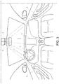
Figure 2 shows a first embodiment of a virtual human-machine interface system when installed on board a vehicle; -
Figure 3 shows a further embodiment of a virtual human-machine interface system; and -
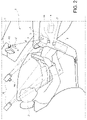
Figure 4 shows by way of example a command given by a user via the virtual human-machine interface system. - Referring initially to
figure 1 , a typical human-machine interface for a vehicle is illustrated which includes ananalog dashboard 100, ascreen 102 and a plurality of physical switches andbuttons 104. - Referring instead to
figure 2 , a first embodiment of a virtual human-machine interface system 1 for a vehicle according to the invention is illustrated. - Such a virtual human-
machine interface system 1 includes at least a first projection surface and a second projection surface disposed within the vehicle. - For example, the
projection surfaces 3 shown in the embodiment infigure 2 are four; in particular, one of them is placed in front of the steering wheel in place of the classic analog or digital dashboard, two of them on the central dashboard of the passenger compartment and one of them on an armrest of a door. Clearly, the number and arrangement ofsuch projection surfaces 3 in other embodiments not shown could also be different. For example, it may also be provided to project an image onto the inner roof of a vehicle. - The human-
machine interface system 1 comprises at least a micro-mirror projection means 5 ("Micromirror MEMS"), arranged to project an image onto said at least oneprojection surface 3. Such a micro-mirror projection means 5 can project an image both on aflat projection surface 3 and on anon-flat projection surface 3. - Clearly, the term "micro-mirror projection means 5" means both a projection means 5 comprising a single micro-mirror and a projection means 5 which comprises a plurality of micro-mirrors.
- Advantageously, in such micro-mirror projection means 5, each micro-mirror can be switched not only between two states but their rotation can be continuous, also allowing the control of the intensity and direction of the incident light. For example, such a projection means 5 can be arranged on the inside roof of the passenger compartment or near a rear-
view mirror 6. Furthermore, multiple projection means 5 can be collected in a single casing for projecting several images simultaneously from the same envelope and consequently minimizing the overall dimensions. It is also possible to use multiple projection means 5 in different positions and/or use mobile projection means 5, if more images are required to be shown to more passengers and/or to move the projection means 5 to change theprojection surface 3 on which to project, for example, to move the projection from an overly illuminated (difficult to read) surface to a less illuminated one. - The human-
machine interface system 1 further comprises at least one sensor means 7 arranged to detect the commands given by a user U by determining the position of a part of the user body inside the vehicle and acontrol unit 9 arranged for the control of the human-machine interface system 1. - The
control unit 9 can be a microprocessor of a control unit which is arranged to execute a program which implements an algorithm for controlling the interface system. Clearly, the connections between the processing unit and the other elements can be optimized in terms of number and length of the cables, or, the control unit can communicate with the other elements via wireless connections. - Furthermore, the
control unit 9 can acquire background illumination of the projection surfaces from brightness sensor means (not shown) and can send both the image data to be projected to a respective projector means 5 and the illumination information detected (depending on the surrounding light). In this way, the projector means 5 can generate a respective image having an illumination calibrated on the illumination information of the background on which the image will be projected. The image data can be for example navigation data (virtual panel) or virtual buttons (virtual switch) for the selection of destinations, etc. - Or, the projector means 5 can project into a part of the dashboard which is the part that is least exposed to ambient lighting.
- Moreover, the position of the projected image can be changed manually, at any time, by the user through a simple dragging action of the image, using the fingers. As the
projection surfaces 3 are at least two, i.e. at least the first projection surface and the second projection surface, the image projected by the at least one projection means 5 can be moved from the first projection surface to the second projection surface by means of a specific command, e.g. dragging the projected image by the user. - In an exemplary embodiment, the dragging action by the user can take place by moving a user's finger in contact with the image projected onto the projection surface towards any direction. The displacement occurring without the contact between the finger and the projected image being lost.
- Video signals require a non-negligible bandwidth, so it may be necessary to use parallel interfaces, for example RGB 24. If the
control unit 9 is placed near the projection means 5 (for example on the same circuit board), the connection can be short and the parallel interface can be used. In this case, thecontrol unit 9 and the projection means 5 can belong to the same electronic control unit. - On the other hand, if the
control unit 9 is not positioned close to the projection means 5, both the projection means 5 and thecontrol unit 9 can comprise a communication module (not shown) which implements a communication protocol (for example, Ethernet), to exchange data and information. In this case, different electronic control units will be present and the presence of a gateway for their interconnection may be necessary. - These last concepts are also applicable between said sensor means 7 and the
control unit 9. - At least one sensor means 7 may be a first vibration sensor means which can detect the vibrations generated by a part of the body of a user that contacts the
projection surface 3. The first vibration sensor means can detect the vibrations being transmitted to theprojection surface 3, due to the contact of saidprojection surface 3 with the user U, to detect the position of a part of the user body on said surface projection and determine a respective command given by a user. For example, said first vibration sensor means can detect a simple touch or drag of a user's U finger on theprojection surface 3. For example, the vibrations detected by said first vibration sensor means can be used in "touch recognition" algorithms to detect a touch or drag of a finger on theprojection surface 3. - In this way, the accuracy of the detection of the commands given by the user is high and is in no way influenced by the lighting conditions inside the vehicle and direct sunlight. Clearly, sensor means 7 may be provided for each projection surface.
- In a further embodiment, in addition or alternatively to the case in which at least one sensor means 7 is a first vibration sensor means, at least one sensor means 7 can also be a distance sensor means 7C which can detect the commands given by the user by determining a distance d of a part of the user's body from the distance sensor means 7C, when arranged between said distance sensor means 7C and the
projection surface 3. - The distance sensor means 7C may generate an
electromagnetic wave 8 and receive anelectromagnetic wave 10 reflected from a reflection area included on a part of the user's body that is placed between said distance sensor means and the projection surface 3 (i.e. on the back of the hand) or, anelectromagnetic wave 10 reflected directly from a reflection area from theprojection surface 3, when no part of the user's body is placed between said distance sensor means 7C and theprojection surface 3. - The distance sensor means 7C can measure a time ΔT between the generation of the
electromagnetic wave 8 and the reception of the reflectedelectromagnetic wave 10 from the distance sensor means 7C, and calculate a distance d between the reflection area and the distance sensor means based on said time ΔT and at the speed of light. - For example, distance d can be calculated using the following formula:

- The distance sensor means 7C is also called time-of-flight sensor. Moreover, the distance sensor means can convert the calculated distance d into an electrical signal to be sent to the
control unit 7. - For example, to interact with the virtual panel, for example to choose the destination or to change the information to be displayed, the user can place his/her hand/finger on the desired part of the projection surface 3 (see
figure 4 ). The distance sensor means 7C, and/or the first vibration means, can transform the reflectedsignal 10 or the vibration signal of the virtual panel, with respect to the user's hand, into electrical signals which will be sent to thecontrol unit 9. The algorithms inside the control unit will understand if and whichvirtual switch 11 of the projected image has been chosen by the user and, consequently, can perform the related operations. For example, editing the image to be projected to display another menu. - Some devices available on the market allow integrating the distance sensor means 7C inside the projector, giving a great advantage in terms of precision, cost and space occupation.
- The virtual human-machine interface system may further comprise a second vibration sensor means 7A and a third vibration sensor means 7B, arranged respectively to detect a vehicle vibrations that are transmitted to the
projection surface 3 and the other the vehicle vibrations that are transmitted to the projection means 5, to compensate the position of the image projected by said projection means 5 on theprojection surface 3 as a function of these vibrations detected. - Vibrations may be due, for example, to the vehicle engine or to a bumpy and uneven road surface.
- As an example, in the embodiment in
figure 2 , the second vibration sensor means 7A is associated with aprojection surface 3 and the third vibration sensor means 7B is associated with a projection means 5 projecting onto said projection surface 3 a which is associated with the second vibration sensor means 7A. - The
control unit 9 can receive the vibration information from such second and third vibration sensor means 7A, 7B in order to be able to perform algorithms for compensating the position of the image on theprojection surface 3. - In a further embodiment, in the aforementioned case in which at least one sensor means 7 is a first vibration sensor means, this first vibration sensor means can also perform the function of said second vibration sensor means 7A. In this case, the first vibration sensor means will be arranged both to detect the vibrations generated by a part of the body of a user and contact the
projection surface 3 and to detect the vibrations of the vehicle transmitted to theprojection surface 3, and the virtual human-machine interface system may comprise a single additional vibration sensor means 7B, i.e. the third vibration sensor means 7B in the preceding case, arranged to detect the vibrations of the vehicle which are transmitted to the projection means 5, to compensate the position of the image projected by said projection means 5 on theprojection surface 3 as a function of such detected vibrations. - In yet a further embodiment, the human-
machine interface system 1 may allow enlarging or reducing the dimension of the projected image, or of at least a portion of the projected image, by approaching or moving away two parts of the user's body that are in contact with the projection surface on which the image is projected and that are sliding on said projection surface. For example, to detect this command, the sensor means described above can be used. These sensor means can also be used to detect a dragging action of the projected image that has been described above in the preceding paragraphs. - The present invention further relates to a virtual human-machine interface method for a vehicle including at least one
projection surface 3 disposed within the vehicle. - The human-machine interface method is controlled by means of a
control unit 9 and comprises the following steps: - projecting an image on the
first projection surface 3 by means of a micro-mirror projection means 5; - detecting commands given by a user by determining the position of a part of the body of a user within the vehicle by means of at least one sensor means 7; and
- changing the position of the image projected by the at least one projection means 5 inside the vehicle, from the first projection surface to the second projection surface, by means of a specific command given by the user.
- The method may further comprise the step of enlarging or reducing the dimension of the projected image, or of at least a portion of the projected image, by approaching or moving away two parts of the user's body that are in contact with the projection surface on which the image is projected and that are sliding on said projection surface.
- In this way, for example, the user is also allowed to display the size of the image writing in a customized manner. This can be particularly useful for visually impaired users or for users with other vision problems.
- The advantages achieved are therefore that of being able to use algorithms and components that are not complex, of projecting images even on non-flat surfaces, of avoiding the installation of touch screens and switches, of not being influenced by direct exposure to the sun and by vibrations of the vehicle, and of allowing a high possibility of customization.
Claims (13)
- A virtual human-machine interface system (1) for a vehicle including at least a first projection surface and a second projection surface being spatially separated from one another and disposed within the vehicle;said virtual human-machine interface system (1) comprising:- at least one micro-mirror projection means (5) arranged for projecting an image on said first projection surface;- at least one sensor means (7) arranged for detecting commands given by a user by determining the position of a part of the user's body within the vehicle; and- a control unit (9) arranged for controlling said human-machine interface system (1);the position of the image projected by the at least one projection means (5) within the vehicle being modifiable by means of a specific command given by the user; andthe image projected by the at least one projection means (5) being moved from the first projection surface to the second projection surface by the user through said specific command.
- A virtual human-machine interface system (1) according to claim 1, wherein the specific command given by the user to modify the position of the projected image inside the passenger compartment is a dragging action of the projected image done by means of a part of the user's body.
- A virtual human-machine interface system (1) according to any of the preceding claims, wherein the projected image, or at least a portion of the projected image, is enlarged or reduced by means of a specific command which involves the approaching or the moving away of two parts of the user's body that are in contact with the projection surface on which the image is projected and which slide on said projection surface.
- A virtual human-machine interface system (1) according to any of the preceding claims, wherein the projection means (5) projects an image on at least one non-flat projection surface (3).
- A virtual human-machine interface system (1) according to any of the preceding claims, wherein at least one sensor means (7) is a first vibration sensor means arranged to detect vibrations generated by a part of the user's body contacting a projection surface (3), so as to detect the position of the part of the user's body and determine a respective command given by said user.
- A virtual human-machine interface system (1) according to any one of the preceding claims, wherein at least one sensor means (7) is a distance sensor means, ToF, (7C) arranged to detect the position of a part of the user's body to determine the commands given by the user by determining a distance (d) from the part of the user's body by the distance sensor means (7C), when placed between said distance sensor means and the projection surface (3).
- A virtual human-machine interface system (1) according to claim 6, wherein said distance sensor means (7C) is arranged for:- generating an electromagnetic wave (8);- receiving an electromagnetic wave (10) reflected from a reflection area (A) included on a part of the user's body that is placed between said distance sensor means and the projection surface (3), or, an electromagnetic wave (10) reflected directly from a reflection area included in the projection surface (3) when no part of the user's body is placed between said distance sensor means and the projection surface (3);- measuring a time ΔT between the generation of the electromagnetic wave (8) and the reception of the reflected electromagnetic wave (10) by the distance sensor means;- calculating a distance (d) between the reflection area and the sensor distance means according to said time ΔT and the speed of light;- converting the calculated distance (d) into an electrical signal to be sent to the control unit (7).
- A virtual human-machine interface system (1) according to claim 7, wherein the distance (d) is calculated by means of the following formula:

- A virtual human-machine interface system (1) according to any of the preceding claims, wherein the projection means (5) projects an image on a projection surface (3) disposed on a vehicle door or on a vehicle dashboard, or disposed in front of a vehicle steering wheel or on the instrument panel of the vehicle or on the internal car roof of a vehicle.
- A virtual human-machine interface system (1) according to any of the preceding claims, wherein the projection means (5) and the control unit (9) comprise a communication module arranged to communicate among them.
- A virtual human-machine interface system (1) according to any one of the preceding claims, further comprising a second vibration sensor means (7A) and a third vibration sensor means (7B) arranged respectively to detect a vehicle vibrations that are transmitted to the projection surface (3) and the other the vehicle vibrations that are transmitted to the projection means (5), to compensate the position of the image projected by said projection means (5) on the projection surface (3) as a function of these vibrations detected.
- A virtual human-machine interface method for a vehicle including at least a first projection surface and a second projection surface being spatially separated from one another and disposed within the vehicle;
said human-machine interface method being controlled by means of a control unit (9) and comprising the steps of:projecting an image on said first projection surface by means of a micro-mirror projection means (5);detecting commands given by a user by determining the position of a part of the body of a user within the vehicle by means of at least one sensor means (7); andchanging the position of the image projected by the at least one projection means (5) inside the vehicle, from the first projection surface to the second projection surface, by means of a specific command given by the user. - A virtual human-machine interface method according to claim 12, further comprising the step of:- enlarging or reducing the dimension of the projected image, or of at least a portion of the projected image, by approaching or moving away two parts of the user's body that are in contact with the projection surface on which the image is projected and that are sliding on said projection surface.
Applications Claiming Priority (2)
| Application Number | Priority Date | Filing Date | Title |
|---|---|---|---|
| IT102017000091628A IT201700091628A1 (en) | 2017-08-08 | 2017-08-08 | Virtual man-machine interface system and corresponding virtual man-machine interface procedure for a vehicle. |
| PCT/IB2018/055924 WO2019030660A1 (en) | 2017-08-08 | 2018-08-07 | Virtual human-machine interface system and corresponding virtual human-machine interface method for a vehicle |
Publications (2)
| Publication Number | Publication Date |
|---|---|
| EP3665029A1 EP3665029A1 (en) | 2020-06-17 |
| EP3665029B1 true EP3665029B1 (en) | 2022-04-20 |
Family
ID=61005997
Family Applications (1)
| Application Number | Title | Priority Date | Filing Date |
|---|---|---|---|
| EP18759754.7A Active EP3665029B1 (en) | 2017-08-08 | 2018-08-07 | Virtual human-machine interface system and corresponding virtual human-machine interface method for a vehicle |
Country Status (5)
| Country | Link |
|---|---|
| US (1) | US11173787B2 (en) |
| EP (1) | EP3665029B1 (en) |
| CN (1) | CN111148649B (en) |
| IT (1) | IT201700091628A1 (en) |
| WO (1) | WO2019030660A1 (en) |
Families Citing this family (8)
| Publication number | Priority date | Publication date | Assignee | Title |
|---|---|---|---|---|
| CN110825271B (en) * | 2019-11-13 | 2024-07-16 | 一汽奔腾轿车有限公司 | Vehicle-mounted AR holographic projection interaction device |
| DE102020124152A1 (en) * | 2020-09-16 | 2022-03-17 | Bayerische Motoren Werke Aktiengesellschaft | Combination of dynamic light projections and surface structures in the vehicle interior |
| KR20220049936A (en) * | 2020-10-15 | 2022-04-22 | 현대모비스 주식회사 | Vehicle sliding module assembly |
| IT202100021302A1 (en) * | 2021-08-05 | 2023-02-05 | Olsa Spa | AMBIENT LIGHTING SYSTEM FOR CARS WITH PROJECTOR OF LOGOS AND/OR SYMBOLS, RELATED CAR AND METHOD FOR PILOTING AND/OR CONTROLLING AN AMBIENT LIGHTING SYSTEM. |
| US20230359321A1 (en) * | 2022-05-03 | 2023-11-09 | Evrdrive, Inc. | System to facilitate purchasing |
| US11975609B1 (en) * | 2023-05-08 | 2024-05-07 | Toyota Motor Engineering & Manufacturing North America Inc. | Systems and methods for selective steering wheel transparency and control of the same |
| FR3159116B1 (en) * | 2024-02-14 | 2026-02-13 | Faurecia Interieur Ind | Upholstery element including a modular touch interface |
| FR3167472A1 (en) * | 2024-10-11 | 2026-04-17 | Stellantis Auto Sas | Interactive display device for displaying control information in a motor vehicle's passenger compartment |
Family Cites Families (14)
| Publication number | Priority date | Publication date | Assignee | Title |
|---|---|---|---|---|
| US7561966B2 (en) * | 2003-12-17 | 2009-07-14 | Denso Corporation | Vehicle information display system |
| DE102009036371A1 (en) * | 2009-08-06 | 2011-04-07 | Volkswagen Ag | Method for providing user interface in vehicle i.e. motor vehicle, involves displaying anchor object for graphical object in display region, where anchor object permits operation of graphical object by operating device |
| EP2372512A1 (en) * | 2010-03-30 | 2011-10-05 | Harman Becker Automotive Systems GmbH | Vehicle user interface unit for a vehicle electronic device |
| SE537730C2 (en) * | 2012-05-14 | 2015-10-06 | Scania Cv Ab | Projected virtual vehicle entry system |
| KR101416378B1 (en) * | 2012-11-27 | 2014-07-09 | 현대자동차 주식회사 | A display apparatus capable of moving image and the method thereof |
| WO2014107513A2 (en) * | 2013-01-04 | 2014-07-10 | Johnson Controls Technology Company | Context-based vehicle user interface reconfiguration |
| CN103324298B (en) * | 2013-06-05 | 2016-06-29 | 海信集团有限公司 | Ultrasonic laser projection keyboard and data inputting method |
| CN105612083B (en) * | 2013-10-09 | 2018-10-23 | 麦格纳覆盖件有限公司 | Systems and methods for controlling vehicle window displays |
| KR101459487B1 (en) * | 2013-12-17 | 2014-11-07 | 현대자동차 주식회사 | Display apparatus for vehicle |
| DE102014216661A1 (en) * | 2014-08-21 | 2016-02-25 | Volkswagen Ag | Device and method for operating multimedia content in a means of transportation |
| US9550406B2 (en) * | 2015-03-16 | 2017-01-24 | Thunder Power Hong Kong Ltd. | Thermal dissipation system of an electric vehicle |
| DE102016209526A1 (en) * | 2015-06-12 | 2016-12-15 | Ford Global Technologies, Llc | A projection device and method for projecting a virtual image into a field of view of a driver of a vehicle |
| JP6432002B2 (en) * | 2016-03-09 | 2018-11-28 | 富士フイルム株式会社 | Projection display device, projection control method, projection control program |
| CN110099817A (en) * | 2016-12-21 | 2019-08-06 | 富士胶片株式会社 | Projection display device, the control method of projection display device, the control program of projection display device |
-
2017
- 2017-08-08 IT IT102017000091628A patent/IT201700091628A1/en unknown
-
2018
- 2018-08-07 CN CN201880051660.9A patent/CN111148649B/en active Active
- 2018-08-07 EP EP18759754.7A patent/EP3665029B1/en active Active
- 2018-08-07 WO PCT/IB2018/055924 patent/WO2019030660A1/en not_active Ceased
- 2018-08-07 US US16/637,411 patent/US11173787B2/en active Active
Also Published As
| Publication number | Publication date |
|---|---|
| EP3665029A1 (en) | 2020-06-17 |
| IT201700091628A1 (en) | 2019-02-08 |
| CN111148649A (en) | 2020-05-12 |
| WO2019030660A1 (en) | 2019-02-14 |
| US11173787B2 (en) | 2021-11-16 |
| CN111148649B (en) | 2023-04-28 |
| US20200192466A1 (en) | 2020-06-18 |
Similar Documents
| Publication | Publication Date | Title |
|---|---|---|
| US11173787B2 (en) | Virtual human-machine interface system and corresponding virtual human-machine interface method for a vehicle | |
| US20140195096A1 (en) | Apparatus and method for contactlessly detecting objects and/or persons and gestures and/or operating procedures made and/or carried out thereby | |
| US9346358B2 (en) | Vehicle control apparatus | |
| CN112135089B (en) | Camera monitoring system for motor vehicle | |
| US9446712B2 (en) | Motor vehicle comprising an electronic rear-view mirror | |
| US10471894B2 (en) | Method and apparatus for controlling vehicular user interface under driving circumstance | |
| US9649938B2 (en) | Method for synchronizing display devices in a motor vehicle | |
| CN106575036B (en) | Method for reducing reflections during operation of a head-up display of a motor vehicle | |
| EP2213501A2 (en) | Reconfigurable vehicle instrument panels | |
| US20120320213A1 (en) | Image display device | |
| JP5136950B2 (en) | In-vehicle device operation device | |
| JP2016503741A (en) | Input device for automobile | |
| US9256325B2 (en) | Curved display apparatus for vehicle | |
| US20190339535A1 (en) | Automatic eye box adjustment | |
| KR20230000505A (en) | Vehicle and method for controlling thereof | |
| US20150274176A1 (en) | Moving amount derivation apparatus | |
| KR101946746B1 (en) | Positioning of non-vehicle objects in the vehicle | |
| CN114008684B (en) | Proper presentation of the position of additional information on a vehicle display unit | |
| JP6600342B2 (en) | Gesture operation method based on depth value and gesture operation system based on depth value | |
| EP4467375A1 (en) | Wireless projection mapping system and method of using the same | |
| US20260124991A1 (en) | Camera monitoring system for motor vehicles | |
| TW202342301A (en) | Windscreen electronics module and vehicle with respective windscreen electronics module | |
| JP2025065063A (en) | Digital rear-view mirror device for easy button or sensor-based operation and method of operation thereof | |
| KR20250050721A (en) | Digital rear mirror for easy operation based on button or sensor, and operating method of the same | |
| KR20140073153A (en) | Three dimension image menu system for vehicle and control method for the same |
Legal Events
| Date | Code | Title | Description |
|---|---|---|---|
| STAA | Information on the status of an ep patent application or granted ep patent |
Free format text: STATUS: UNKNOWN |
|
| STAA | Information on the status of an ep patent application or granted ep patent |
Free format text: STATUS: THE INTERNATIONAL PUBLICATION HAS BEEN MADE |
|
| PUAI | Public reference made under article 153(3) epc to a published international application that has entered the european phase |
Free format text: ORIGINAL CODE: 0009012 |
|
| STAA | Information on the status of an ep patent application or granted ep patent |
Free format text: STATUS: REQUEST FOR EXAMINATION WAS MADE |
|
| 17P | Request for examination filed |
Effective date: 20200226 |
|
| AK | Designated contracting states |
Kind code of ref document: A1 Designated state(s): AL AT BE BG CH CY CZ DE DK EE ES FI FR GB GR HR HU IE IS IT LI LT LU LV MC MK MT NL NO PL PT RO RS SE SI SK SM TR |
|
| AX | Request for extension of the european patent |
Extension state: BA ME |
|
| DAV | Request for validation of the european patent (deleted) | ||
| DAX | Request for extension of the european patent (deleted) | ||
| GRAP | Despatch of communication of intention to grant a patent |
Free format text: ORIGINAL CODE: EPIDOSNIGR1 |
|
| STAA | Information on the status of an ep patent application or granted ep patent |
Free format text: STATUS: GRANT OF PATENT IS INTENDED |
|
| INTG | Intention to grant announced |
Effective date: 20211116 |
|
| GRAS | Grant fee paid |
Free format text: ORIGINAL CODE: EPIDOSNIGR3 |
|
| GRAA | (expected) grant |
Free format text: ORIGINAL CODE: 0009210 |
|
| STAA | Information on the status of an ep patent application or granted ep patent |
Free format text: STATUS: THE PATENT HAS BEEN GRANTED |
|
| AK | Designated contracting states |
Kind code of ref document: B1 Designated state(s): AL AT BE BG CH CY CZ DE DK EE ES FI FR GB GR HR HU IE IS IT LI LT LU LV MC MK MT NL NO PL PT RO RS SE SI SK SM TR |
|
| REG | Reference to a national code |
Ref country code: GB Ref legal event code: FG4D |
|
| REG | Reference to a national code |
Ref country code: CH Ref legal event code: EP |
|
| REG | Reference to a national code |
Ref country code: DE Ref legal event code: R096 Ref document number: 602018034195 Country of ref document: DE |
|
| REG | Reference to a national code |
Ref country code: IE Ref legal event code: FG4D |
|
| REG | Reference to a national code |
Ref country code: AT Ref legal event code: REF Ref document number: 1484922 Country of ref document: AT Kind code of ref document: T Effective date: 20220515 |
|
| REG | Reference to a national code |
Ref country code: LT Ref legal event code: MG9D |
|
| REG | Reference to a national code |
Ref country code: NL Ref legal event code: MP Effective date: 20220420 |
|
| REG | Reference to a national code |
Ref country code: AT Ref legal event code: MK05 Ref document number: 1484922 Country of ref document: AT Kind code of ref document: T Effective date: 20220420 |
|
| PG25 | Lapsed in a contracting state [announced via postgrant information from national office to epo] |
Ref country code: NL Free format text: LAPSE BECAUSE OF FAILURE TO SUBMIT A TRANSLATION OF THE DESCRIPTION OR TO PAY THE FEE WITHIN THE PRESCRIBED TIME-LIMIT Effective date: 20220420 |
|
| PG25 | Lapsed in a contracting state [announced via postgrant information from national office to epo] |
Ref country code: SE Free format text: LAPSE BECAUSE OF FAILURE TO SUBMIT A TRANSLATION OF THE DESCRIPTION OR TO PAY THE FEE WITHIN THE PRESCRIBED TIME-LIMIT Effective date: 20220420 Ref country code: PT Free format text: LAPSE BECAUSE OF FAILURE TO SUBMIT A TRANSLATION OF THE DESCRIPTION OR TO PAY THE FEE WITHIN THE PRESCRIBED TIME-LIMIT Effective date: 20220822 Ref country code: NO Free format text: LAPSE BECAUSE OF FAILURE TO SUBMIT A TRANSLATION OF THE DESCRIPTION OR TO PAY THE FEE WITHIN THE PRESCRIBED TIME-LIMIT Effective date: 20220720 Ref country code: LT Free format text: LAPSE BECAUSE OF FAILURE TO SUBMIT A TRANSLATION OF THE DESCRIPTION OR TO PAY THE FEE WITHIN THE PRESCRIBED TIME-LIMIT Effective date: 20220420 Ref country code: HR Free format text: LAPSE BECAUSE OF FAILURE TO SUBMIT A TRANSLATION OF THE DESCRIPTION OR TO PAY THE FEE WITHIN THE PRESCRIBED TIME-LIMIT Effective date: 20220420 Ref country code: GR Free format text: LAPSE BECAUSE OF FAILURE TO SUBMIT A TRANSLATION OF THE DESCRIPTION OR TO PAY THE FEE WITHIN THE PRESCRIBED TIME-LIMIT Effective date: 20220721 Ref country code: FI Free format text: LAPSE BECAUSE OF FAILURE TO SUBMIT A TRANSLATION OF THE DESCRIPTION OR TO PAY THE FEE WITHIN THE PRESCRIBED TIME-LIMIT Effective date: 20220420 Ref country code: ES Free format text: LAPSE BECAUSE OF FAILURE TO SUBMIT A TRANSLATION OF THE DESCRIPTION OR TO PAY THE FEE WITHIN THE PRESCRIBED TIME-LIMIT Effective date: 20220420 Ref country code: BG Free format text: LAPSE BECAUSE OF FAILURE TO SUBMIT A TRANSLATION OF THE DESCRIPTION OR TO PAY THE FEE WITHIN THE PRESCRIBED TIME-LIMIT Effective date: 20220720 Ref country code: AT Free format text: LAPSE BECAUSE OF FAILURE TO SUBMIT A TRANSLATION OF THE DESCRIPTION OR TO PAY THE FEE WITHIN THE PRESCRIBED TIME-LIMIT Effective date: 20220420 |
|
| PG25 | Lapsed in a contracting state [announced via postgrant information from national office to epo] |
Ref country code: RS Free format text: LAPSE BECAUSE OF FAILURE TO SUBMIT A TRANSLATION OF THE DESCRIPTION OR TO PAY THE FEE WITHIN THE PRESCRIBED TIME-LIMIT Effective date: 20220420 Ref country code: PL Free format text: LAPSE BECAUSE OF FAILURE TO SUBMIT A TRANSLATION OF THE DESCRIPTION OR TO PAY THE FEE WITHIN THE PRESCRIBED TIME-LIMIT Effective date: 20220420 Ref country code: LV Free format text: LAPSE BECAUSE OF FAILURE TO SUBMIT A TRANSLATION OF THE DESCRIPTION OR TO PAY THE FEE WITHIN THE PRESCRIBED TIME-LIMIT Effective date: 20220420 Ref country code: IS Free format text: LAPSE BECAUSE OF FAILURE TO SUBMIT A TRANSLATION OF THE DESCRIPTION OR TO PAY THE FEE WITHIN THE PRESCRIBED TIME-LIMIT Effective date: 20220820 |
|
| REG | Reference to a national code |
Ref country code: DE Ref legal event code: R097 Ref document number: 602018034195 Country of ref document: DE |
|
| PG25 | Lapsed in a contracting state [announced via postgrant information from national office to epo] |
Ref country code: SM Free format text: LAPSE BECAUSE OF FAILURE TO SUBMIT A TRANSLATION OF THE DESCRIPTION OR TO PAY THE FEE WITHIN THE PRESCRIBED TIME-LIMIT Effective date: 20220420 Ref country code: SK Free format text: LAPSE BECAUSE OF FAILURE TO SUBMIT A TRANSLATION OF THE DESCRIPTION OR TO PAY THE FEE WITHIN THE PRESCRIBED TIME-LIMIT Effective date: 20220420 Ref country code: RO Free format text: LAPSE BECAUSE OF FAILURE TO SUBMIT A TRANSLATION OF THE DESCRIPTION OR TO PAY THE FEE WITHIN THE PRESCRIBED TIME-LIMIT Effective date: 20220420 Ref country code: EE Free format text: LAPSE BECAUSE OF FAILURE TO SUBMIT A TRANSLATION OF THE DESCRIPTION OR TO PAY THE FEE WITHIN THE PRESCRIBED TIME-LIMIT Effective date: 20220420 Ref country code: DK Free format text: LAPSE BECAUSE OF FAILURE TO SUBMIT A TRANSLATION OF THE DESCRIPTION OR TO PAY THE FEE WITHIN THE PRESCRIBED TIME-LIMIT Effective date: 20220420 Ref country code: CZ Free format text: LAPSE BECAUSE OF FAILURE TO SUBMIT A TRANSLATION OF THE DESCRIPTION OR TO PAY THE FEE WITHIN THE PRESCRIBED TIME-LIMIT Effective date: 20220420 |
|
| PLBE | No opposition filed within time limit |
Free format text: ORIGINAL CODE: 0009261 |
|
| STAA | Information on the status of an ep patent application or granted ep patent |
Free format text: STATUS: NO OPPOSITION FILED WITHIN TIME LIMIT |
|
| 26N | No opposition filed |
Effective date: 20230123 |
|
| PG25 | Lapsed in a contracting state [announced via postgrant information from national office to epo] |
Ref country code: MC Free format text: LAPSE BECAUSE OF FAILURE TO SUBMIT A TRANSLATION OF THE DESCRIPTION OR TO PAY THE FEE WITHIN THE PRESCRIBED TIME-LIMIT Effective date: 20220420 Ref country code: AL Free format text: LAPSE BECAUSE OF FAILURE TO SUBMIT A TRANSLATION OF THE DESCRIPTION OR TO PAY THE FEE WITHIN THE PRESCRIBED TIME-LIMIT Effective date: 20220420 |
|
| REG | Reference to a national code |
Ref country code: CH Ref legal event code: PL |
|
| GBPC | Gb: european patent ceased through non-payment of renewal fee |
Effective date: 20220807 |
|
| PG25 | Lapsed in a contracting state [announced via postgrant information from national office to epo] |
Ref country code: LU Free format text: LAPSE BECAUSE OF NON-PAYMENT OF DUE FEES Effective date: 20220807 Ref country code: LI Free format text: LAPSE BECAUSE OF NON-PAYMENT OF DUE FEES Effective date: 20220831 Ref country code: CH Free format text: LAPSE BECAUSE OF NON-PAYMENT OF DUE FEES Effective date: 20220831 |
|
| REG | Reference to a national code |
Ref country code: BE Ref legal event code: MM Effective date: 20220831 |
|
| PG25 | Lapsed in a contracting state [announced via postgrant information from national office to epo] |
Ref country code: SI Free format text: LAPSE BECAUSE OF FAILURE TO SUBMIT A TRANSLATION OF THE DESCRIPTION OR TO PAY THE FEE WITHIN THE PRESCRIBED TIME-LIMIT Effective date: 20220420 |
|
| P01 | Opt-out of the competence of the unified patent court (upc) registered |
Effective date: 20230526 |
|
| PG25 | Lapsed in a contracting state [announced via postgrant information from national office to epo] |
Ref country code: IE Free format text: LAPSE BECAUSE OF NON-PAYMENT OF DUE FEES Effective date: 20220807 |
|
| PG25 | Lapsed in a contracting state [announced via postgrant information from national office to epo] |
Ref country code: BE Free format text: LAPSE BECAUSE OF NON-PAYMENT OF DUE FEES Effective date: 20220831 |
|
| PG25 | Lapsed in a contracting state [announced via postgrant information from national office to epo] |
Ref country code: GB Free format text: LAPSE BECAUSE OF NON-PAYMENT OF DUE FEES Effective date: 20220807 |
|
| REG | Reference to a national code |
Ref country code: DE Ref legal event code: R079 Ref document number: 602018034195 Country of ref document: DE Free format text: PREVIOUS MAIN CLASS: B60K0037060000 Ipc: B60K0035100000 |
|
| PG25 | Lapsed in a contracting state [announced via postgrant information from national office to epo] |
Ref country code: IT Free format text: LAPSE BECAUSE OF FAILURE TO SUBMIT A TRANSLATION OF THE DESCRIPTION OR TO PAY THE FEE WITHIN THE PRESCRIBED TIME-LIMIT Effective date: 20220420 |
|
| PG25 | Lapsed in a contracting state [announced via postgrant information from national office to epo] |
Ref country code: CY Free format text: LAPSE BECAUSE OF FAILURE TO SUBMIT A TRANSLATION OF THE DESCRIPTION OR TO PAY THE FEE WITHIN THE PRESCRIBED TIME-LIMIT Effective date: 20220420 |
|
| PG25 | Lapsed in a contracting state [announced via postgrant information from national office to epo] |
Ref country code: MK Free format text: LAPSE BECAUSE OF FAILURE TO SUBMIT A TRANSLATION OF THE DESCRIPTION OR TO PAY THE FEE WITHIN THE PRESCRIBED TIME-LIMIT Effective date: 20220420 Ref country code: HU Free format text: LAPSE BECAUSE OF FAILURE TO SUBMIT A TRANSLATION OF THE DESCRIPTION OR TO PAY THE FEE WITHIN THE PRESCRIBED TIME-LIMIT; INVALID AB INITIO Effective date: 20180807 |
|
| PG25 | Lapsed in a contracting state [announced via postgrant information from national office to epo] |
Ref country code: MT Free format text: LAPSE BECAUSE OF FAILURE TO SUBMIT A TRANSLATION OF THE DESCRIPTION OR TO PAY THE FEE WITHIN THE PRESCRIBED TIME-LIMIT Effective date: 20220420 |
|
| PG25 | Lapsed in a contracting state [announced via postgrant information from national office to epo] |
Ref country code: BG Free format text: LAPSE BECAUSE OF FAILURE TO SUBMIT A TRANSLATION OF THE DESCRIPTION OR TO PAY THE FEE WITHIN THE PRESCRIBED TIME-LIMIT Effective date: 20220420 |
|
| PG25 | Lapsed in a contracting state [announced via postgrant information from national office to epo] |
Ref country code: BG Free format text: LAPSE BECAUSE OF FAILURE TO SUBMIT A TRANSLATION OF THE DESCRIPTION OR TO PAY THE FEE WITHIN THE PRESCRIBED TIME-LIMIT Effective date: 20220420 |
|
| PGFP | Annual fee paid to national office [announced via postgrant information from national office to epo] |
Ref country code: DE Payment date: 20250724 Year of fee payment: 8 |
|
| PGFP | Annual fee paid to national office [announced via postgrant information from national office to epo] |
Ref country code: FR Payment date: 20250723 Year of fee payment: 8 |
|
| PGFP | Annual fee paid to national office [announced via postgrant information from national office to epo] |
Ref country code: TR Payment date: 20260123 Year of fee payment: 8 |