EP3664225A1 - High-current connector - Google Patents
High-current connector Download PDFInfo
- Publication number
- EP3664225A1 EP3664225A1 EP19173472.2A EP19173472A EP3664225A1 EP 3664225 A1 EP3664225 A1 EP 3664225A1 EP 19173472 A EP19173472 A EP 19173472A EP 3664225 A1 EP3664225 A1 EP 3664225A1
- Authority
- EP
- European Patent Office
- Prior art keywords
- output
- contact
- input
- current connector
- shell
- Prior art date
- Legal status (The legal status is an assumption and is not a legal conclusion. Google has not performed a legal analysis and makes no representation as to the accuracy of the status listed.)
- Withdrawn
Links
- RYGMFSIKBFXOCR-UHFFFAOYSA-N Copper Chemical compound [Cu] RYGMFSIKBFXOCR-UHFFFAOYSA-N 0.000 claims description 11
- 229910052802 copper Inorganic materials 0.000 claims description 11
- 239000010949 copper Substances 0.000 claims description 11
- 239000000463 material Substances 0.000 abstract description 2
- 238000009964 serging Methods 0.000 abstract description 2
- 206010014357 Electric shock Diseases 0.000 description 9
- 238000010586 diagram Methods 0.000 description 3
- 230000004075 alteration Effects 0.000 description 1
- 230000007812 deficiency Effects 0.000 description 1
- 230000000694 effects Effects 0.000 description 1
- 230000035515 penetration Effects 0.000 description 1
Images


Classifications
-
- H—ELECTRICITY
- H01—ELECTRIC ELEMENTS
- H01R—ELECTRICALLY-CONDUCTIVE CONNECTIONS; STRUCTURAL ASSOCIATIONS OF A PLURALITY OF MUTUALLY-INSULATED ELECTRICAL CONNECTING ELEMENTS; COUPLING DEVICES; CURRENT COLLECTORS
- H01R13/00—Details of coupling devices of the kinds covered by groups H01R12/70 or H01R24/00 - H01R33/00
- H01R13/46—Bases; Cases
- H01R13/502—Bases; Cases composed of different pieces
- H01R13/506—Bases; Cases composed of different pieces assembled by snap action of the parts
-
- H—ELECTRICITY
- H01—ELECTRIC ELEMENTS
- H01R—ELECTRICALLY-CONDUCTIVE CONNECTIONS; STRUCTURAL ASSOCIATIONS OF A PLURALITY OF MUTUALLY-INSULATED ELECTRICAL CONNECTING ELEMENTS; COUPLING DEVICES; CURRENT COLLECTORS
- H01R11/00—Individual connecting elements providing two or more spaced connecting locations for conductive members which are, or may be, thereby interconnected, e.g. end pieces for wires or cables supported by the wire or cable and having means for facilitating electrical connection to some other wire, terminal, or conductive member, blocks of binding posts
- H01R11/11—End pieces or tapping pieces for wires, supported by the wire and for facilitating electrical connection to some other wire, terminal or conductive member
- H01R11/26—End pieces terminating in a screw clamp, screw or nut
-
- H—ELECTRICITY
- H01—ELECTRIC ELEMENTS
- H01M—PROCESSES OR MEANS, e.g. BATTERIES, FOR THE DIRECT CONVERSION OF CHEMICAL ENERGY INTO ELECTRICAL ENERGY
- H01M50/00—Constructional details or processes of manufacture of the non-active parts of electrochemical cells other than fuel cells, e.g. hybrid cells
- H01M50/50—Current conducting connections for cells or batteries
- H01M50/543—Terminals
- H01M50/552—Terminals characterised by their shape
-
- H—ELECTRICITY
- H01—ELECTRIC ELEMENTS
- H01M—PROCESSES OR MEANS, e.g. BATTERIES, FOR THE DIRECT CONVERSION OF CHEMICAL ENERGY INTO ELECTRICAL ENERGY
- H01M50/00—Constructional details or processes of manufacture of the non-active parts of electrochemical cells other than fuel cells, e.g. hybrid cells
- H01M50/50—Current conducting connections for cells or batteries
- H01M50/543—Terminals
- H01M50/564—Terminals characterised by their manufacturing process
-
- H—ELECTRICITY
- H01—ELECTRIC ELEMENTS
- H01R—ELECTRICALLY-CONDUCTIVE CONNECTIONS; STRUCTURAL ASSOCIATIONS OF A PLURALITY OF MUTUALLY-INSULATED ELECTRICAL CONNECTING ELEMENTS; COUPLING DEVICES; CURRENT COLLECTORS
- H01R13/00—Details of coupling devices of the kinds covered by groups H01R12/70 or H01R24/00 - H01R33/00
- H01R13/62—Means for facilitating engagement or disengagement of coupling parts or for holding them in engagement
- H01R13/621—Bolt, set screw or screw clamp
- H01R13/6215—Bolt, set screw or screw clamp using one or more bolts
-
- H—ELECTRICITY
- H01—ELECTRIC ELEMENTS
- H01R—ELECTRICALLY-CONDUCTIVE CONNECTIONS; STRUCTURAL ASSOCIATIONS OF A PLURALITY OF MUTUALLY-INSULATED ELECTRICAL CONNECTING ELEMENTS; COUPLING DEVICES; CURRENT COLLECTORS
- H01R13/00—Details of coupling devices of the kinds covered by groups H01R12/70 or H01R24/00 - H01R33/00
- H01R13/64—Means for preventing incorrect coupling
- H01R13/642—Means for preventing incorrect coupling by position or shape of contact members
-
- H—ELECTRICITY
- H01—ELECTRIC ELEMENTS
- H01R—ELECTRICALLY-CONDUCTIVE CONNECTIONS; STRUCTURAL ASSOCIATIONS OF A PLURALITY OF MUTUALLY-INSULATED ELECTRICAL CONNECTING ELEMENTS; COUPLING DEVICES; CURRENT COLLECTORS
- H01R35/00—Flexible or turnable line connectors, i.e. the rotation angle being limited
-
- H—ELECTRICITY
- H01—ELECTRIC ELEMENTS
- H01R—ELECTRICALLY-CONDUCTIVE CONNECTIONS; STRUCTURAL ASSOCIATIONS OF A PLURALITY OF MUTUALLY-INSULATED ELECTRICAL CONNECTING ELEMENTS; COUPLING DEVICES; CURRENT COLLECTORS
- H01R4/00—Electrically-conductive connections between two or more conductive members in direct contact, i.e. touching one another; Means for effecting or maintaining such contact; Electrically-conductive connections having two or more spaced connecting locations for conductors and using contact members penetrating insulation
- H01R4/28—Clamped connections, spring connections
- H01R4/30—Clamped connections, spring connections utilising a screw or nut clamping member
- H01R4/34—Conductive members located under head of screw
-
- H—ELECTRICITY
- H01—ELECTRIC ELEMENTS
- H01M—PROCESSES OR MEANS, e.g. BATTERIES, FOR THE DIRECT CONVERSION OF CHEMICAL ENERGY INTO ELECTRICAL ENERGY
- H01M2220/00—Batteries for particular applications
- H01M2220/20—Batteries in motive systems, e.g. vehicle, ship, plane
-
- H—ELECTRICITY
- H01—ELECTRIC ELEMENTS
- H01R—ELECTRICALLY-CONDUCTIVE CONNECTIONS; STRUCTURAL ASSOCIATIONS OF A PLURALITY OF MUTUALLY-INSULATED ELECTRICAL CONNECTING ELEMENTS; COUPLING DEVICES; CURRENT COLLECTORS
- H01R13/00—Details of coupling devices of the kinds covered by groups H01R12/70 or H01R24/00 - H01R33/00
- H01R13/44—Means for preventing access to live contacts
-
- H—ELECTRICITY
- H01—ELECTRIC ELEMENTS
- H01R—ELECTRICALLY-CONDUCTIVE CONNECTIONS; STRUCTURAL ASSOCIATIONS OF A PLURALITY OF MUTUALLY-INSULATED ELECTRICAL CONNECTING ELEMENTS; COUPLING DEVICES; CURRENT COLLECTORS
- H01R4/00—Electrically-conductive connections between two or more conductive members in direct contact, i.e. touching one another; Means for effecting or maintaining such contact; Electrically-conductive connections having two or more spaced connecting locations for conductors and using contact members penetrating insulation
- H01R4/70—Insulation of connections
Definitions
- the present application relates to a connector and in particular to a high-current connector.
- an output pole of a module is directly connected to an output copper bay by a screw, so that the mounting is troublesome and no anti-electric shock function is provided. Therefore, during the battery assembly, the worker is likely to touch the output positive pole of a module without the anti-electric shock function, resulting in an electric shock risk.
- High-current connectors with the anti-electric shock function are complex in structure and high in cost.
- the output direction of majority of the existing connectors is fixed, so the output direction of the connectors cannot be arbitrarily adjusted by 360° as required.
- a technical problem to be solved by the present application is to overcome the deficiencies of the prior art and provide a high-current connector.
- the high-current connector includes an input portion and an output portion, wherein the input portion includes a first shell, an input contact and a fastener, with a connecting hole being formed on the input contact; the output portion includes a second shell, an output contact and a connecting base, with the output contact being sheathed on the connecting base; when the input portion and the output portion are connected, one end of the fastener passes through the connecting hole to be fixed to the connecting base, while the other end thereof is limited onto the first shell or the input contact; and, the input contact is conductively connected to the output contact.
- a groove is formed in a middle portion of the connecting base, and internal threads are provided inside the groove;
- the fastener includes a rod body on which external threads are provided; and the rod body passes through the connecting hole to be in threaded connection to the connecting base.
- a first limiting cap is provided at one end of the rod body, while an insulating cap is provided at the other end thereof; and, the first limiting cap is limited onto the first shell or the input contact, and the end where the insulating cap is provided passes through the connecting hole.
- a convex column is provided in the center of an end face of an end of the rod body away from the first limiting cap, the diameter of the convex column is less than that of the rod body, the insulating cap is sheathed on the convex column, and the outer diameter of the insulating cap is not greater than the diameter of the rod body.
- the input portion further includes a main circuit copper bar that is conductively connected to the input contact; and, a first mounting port is formed at a position on the first shell corresponding to the first limiting cap, and a first cover plate is disposed over the first mounting port.
- the aperture of the connecting hole is the same as the diameter of the rod body, and internal threads fitted with the external threads on the rod body are provided on an inner wall of the connecting hole.
- the connecting base includes a barrel body; a second limiting cap is provided at one end of the barrel body, while an insulating ring is sheathed on the other end thereof; and, the second limiting cap is limited onto the second shell or the output contact, and the end where the insulating ring is provided passes through the output contact.
- An outer edge of the insulating ring is protruded from an end face of the barrel body.
- the connecting base is in threaded connection to the output contact.
- the output portion further includes an output copper bar that is conductively connected to the output contact.
- the high-current connector provided by the present application has the following technical effects.
- this embodiment provides a high-current connector, including an input portion 1 and an output portion 2.
- the input portion 1 includes a first shell 11, an input contact 12 and a fastener 13.
- a connecting hole is formed on the input contact 12.
- the output portion 2 includes a second shell 21, an output contact 22 and a connecting base 23.
- the output contact 22 is sheathed on the connecting base 23.
- the input portion and the output portion are connected and fixed internally, so the size is reduced and the mounting space is saved. Since the internal structures are arranged in a penetration manner or in a sheathed manner, the output direction of the connector can be arbitrarily adjusted by 360° as required.
- the fastener 13 and the connecting base 23 may be connected by clipping, threaded connection or in other ways.
- the threaded connection is used.
- a groove is formed in a middle portion of the connecting base 23, and internal threads are provided inside the groove.
- the fastener 13 includes a rod body 131 on which external threads are provided. The rod body passes through the connecting hole to be in threaded connection to the connecting base. In this way, the connection mode is simple, firm and difficult to damage, it is easy to assemble and disassemble, and the tightness degree during mounting can be controlled according to the distance, so that no loosening is ensured.
- a first limiting cap 132 is provided at one end of the rod body 131, while an insulating cap 14 is provided at the other end thereof.
- the first limiting cap 132 is limited onto the first shell 11 or the input contact 12, and the end where the insulating cap 14 is provided passes through the connecting hole.
- a convex column 133 is provided in the center of an end face of an end of the rod body 131 away from the first limiting cap 132.
- the diameter of the convex column is less than that of the rod body.
- the insulating cap is sheathed on the convex column, and the outer diameter of the insulating cap is not greater than the diameter of the rod body.
- the input portion 1 further includes a main circuit copper bar 15 that is conductively connected to the input contact 12.
- the input contact 12 is pressed into the main circuit copper bar by rivet-pressing.
- a first mounting port is formed at a position on the first shell 11 corresponding to the first limiting cap 132, and a first cover plate 111 is disposed over the first mounting port.
- the aperture of the connecting hole is the same as the diameter of the rod body, and internal threads fitted with the external threads on the rod body are provided on an inner wall of the connecting hole.
- the connecting base 23 includes a barrel body 231.
- a second limiting cap 232 is provided at one end of the barrel body, while an insulating ring 24 is sheathed on the other end thereof.
- the second limiting cap is limited onto the second shell or the output contact, and the end where the insulating ring is provided passes through the output contact.
- An outer edge of the insulating ring is protruded from an end face of the barrel body.
- the connecting base is in threaded connection to the output contact.
- the output portion further includes an output copper bar 25 that is conductively connected to the output contact.
- the output contact is pressed into the output copper bar by rivet-pressing.
- a second mounting port is formed at a position on the second shell corresponding to the second limiting cap, and a second cover plate is disposed over the second mounting port.
Landscapes
- Chemical & Material Sciences (AREA)
- Chemical Kinetics & Catalysis (AREA)
- Electrochemistry (AREA)
- General Chemical & Material Sciences (AREA)
- Engineering & Computer Science (AREA)
- Manufacturing & Machinery (AREA)
- Connector Housings Or Holding Contact Members (AREA)
Abstract
Description
- The present application claims the priority of Chinese Patent Application NO.
201811479476.2, filed on December 5, 2018 - The present application relates to a connector and in particular to a high-current connector.
- Existing battery packs for new energy automobiles are limited in overall size, and the layout space for internal modules is small. However, existing high-voltage and high-current connectors are used outside the battery packs, and require a large mounting space and a large operation space, so these connectors cannot meet the internal requirements of the battery packs.
- As for the existing connectors for battery modules in the battery packs, an output pole of a module is directly connected to an output copper bay by a screw, so that the mounting is troublesome and no anti-electric shock function is provided. Therefore, during the battery assembly, the worker is likely to touch the output positive pole of a module without the anti-electric shock function, resulting in an electric shock risk. High-current connectors with the anti-electric shock function are complex in structure and high in cost.
- The output direction of majority of the existing connectors is fixed, so the output direction of the connectors cannot be arbitrarily adjusted by 360° as required.
- A technical problem to be solved by the present application is to overcome the deficiencies of the prior art and provide a high-current connector.
- Main technical solutions of the high-current connector provided by the present application will be described below.
- The high-current connector includes an input portion and an output portion, wherein the input portion includes a first shell, an input contact and a fastener, with a connecting hole being formed on the input contact; the output portion includes a second shell, an output contact and a connecting base, with the output contact being sheathed on the connecting base; when the input portion and the output portion are connected, one end of the fastener passes through the connecting hole to be fixed to the connecting base, while the other end thereof is limited onto the first shell or the input contact; and, the input contact is conductively connected to the output contact.
- A groove is formed in a middle portion of the connecting base, and internal threads are provided inside the groove; the fastener includes a rod body on which external threads are provided; and the rod body passes through the connecting hole to be in threaded connection to the connecting base.
- A first limiting cap is provided at one end of the rod body, while an insulating cap is provided at the other end thereof; and, the first limiting cap is limited onto the first shell or the input contact, and the end where the insulating cap is provided passes through the connecting hole.
- A convex column is provided in the center of an end face of an end of the rod body away from the first limiting cap, the diameter of the convex column is less than that of the rod body, the insulating cap is sheathed on the convex column, and the outer diameter of the insulating cap is not greater than the diameter of the rod body.
- The input portion further includes a main circuit copper bar that is conductively connected to the input contact; and, a first mounting port is formed at a position on the first shell corresponding to the first limiting cap, and a first cover plate is disposed over the first mounting port.
- The aperture of the connecting hole is the same as the diameter of the rod body, and internal threads fitted with the external threads on the rod body are provided on an inner wall of the connecting hole.
- The connecting base includes a barrel body; a second limiting cap is provided at one end of the barrel body, while an insulating ring is sheathed on the other end thereof; and, the second limiting cap is limited onto the second shell or the output contact, and the end where the insulating ring is provided passes through the output contact.
- An outer edge of the insulating ring is protruded from an end face of the barrel body.
- The connecting base is in threaded connection to the output contact.
- The output portion further includes an output copper bar that is conductively connected to the output contact.
- The high-current connector provided by the present application has the following technical effects.
- 1. The input portion and the output portion are connected by screws and nuts in an over-locking manner, so it is easy to mount, both the material and space are saved, and it is ensured that the input portion and the output portion will not become loose during the vehicle vibration.
- 2. The high-current connector is small in size and has an IPXXB anti-electric shock function in the case of a large carrier current.
- 3. The output direction of the connection can be arbitrarily adjusted by 360° as required.
-
-
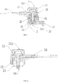
Fig. 1 is a structure diagram of a high-current connector according to an embodiment of the present application; -
Fig. 2 is a structure diagram of an input portion of the high-current connector according to an embodiment of the present application; -
Fig. 3 is a structure diagram of an output portion of the high-current connector according to an embodiment of the present application; -
Fig. 4 is an exploded view of the input portion of the high-current connector according to an embodiment of the present application; -
Fig. 5 is an exploded view of the output portion of the high-current connector according to an embodiment of the present application; -
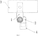
Fig. 6 shows a first connection mode of the high-current connector according to an embodiment of the present application; and -
Fig. 7 shows a second connection mode of the high-current connector according to an embodiment of the present application;
in which:
1: input portion; 11: first shell; 111: first cover plate; 12: input contact; 13: fastener; 131: rod body; 132: first limiting cap; 133: convex column; 14: insulating cap; 15: main circuit copper bar; 2: output portion; 21: second shell; 211: second cover plate; 22: output contact; 23: connecting base; 231: barrel body; 232: second limiting cap; 24: insulating ring; 25: output copper bar; 3: main circuit input end; and, 4: battery module. - The present application will be described below in detail by embodiments with references to the accompanying drawings. It is to be pointed out that the described embodiments are merely for understanding the present application, rather than limiting the present application.
- As shown in
Figs. 1-7 , this embodiment provides a high-current connector, including aninput portion 1 and anoutput portion 2. Theinput portion 1 includes afirst shell 11, aninput contact 12 and afastener 13. A connecting hole is formed on theinput contact 12. Theoutput portion 2 includes asecond shell 21, anoutput contact 22 and aconnecting base 23. Theoutput contact 22 is sheathed on the connectingbase 23. When the input portion and the output portion are connected, one end of thefastener 13 passes through the connecting hole to be fixed to the connectingbase 23, while the other end thereof is limited onto thefirst shell 11 or theinput contact 12. Theinput contact 12 is conductively connected to theoutput contact 22. - In this way, the input portion and the output portion are connected and fixed internally, so the size is reduced and the mounting space is saved. Since the internal structures are arranged in a penetration manner or in a sheathed manner, the output direction of the connector can be arbitrarily adjusted by 360° as required.
- The
fastener 13 and theconnecting base 23 may be connected by clipping, threaded connection or in other ways. Preferably, the threaded connection is used. A groove is formed in a middle portion of the connectingbase 23, and internal threads are provided inside the groove. Thefastener 13 includes arod body 131 on which external threads are provided. The rod body passes through the connecting hole to be in threaded connection to the connecting base. In this way, the connection mode is simple, firm and difficult to damage, it is easy to assemble and disassemble, and the tightness degree during mounting can be controlled according to the distance, so that no loosening is ensured. - A first limiting
cap 132 is provided at one end of therod body 131, while aninsulating cap 14 is provided at the other end thereof. The firstlimiting cap 132 is limited onto thefirst shell 11 or theinput contact 12, and the end where theinsulating cap 14 is provided passes through the connecting hole. - A
convex column 133 is provided in the center of an end face of an end of therod body 131 away from the first limitingcap 132. The diameter of the convex column is less than that of the rod body. The insulating cap is sheathed on the convex column, and the outer diameter of the insulating cap is not greater than the diameter of the rod body. In this way, an IPXXB anti-electric shock function is provided in the case of a large carrier current. The IPXXB anti-electric shock function is also provided on the basis of transporting a 400A large current, so the safety of the assembler is ensured. - The
input portion 1 further includes a maincircuit copper bar 15 that is conductively connected to theinput contact 12. Preferably, theinput contact 12 is pressed into the main circuit copper bar by rivet-pressing. - A first mounting port is formed at a position on the
first shell 11 corresponding to the first limitingcap 132, and afirst cover plate 111 is disposed over the first mounting port. - The aperture of the connecting hole is the same as the diameter of the rod body, and internal threads fitted with the external threads on the rod body are provided on an inner wall of the connecting hole.
- The connecting
base 23 includes abarrel body 231. A second limitingcap 232 is provided at one end of the barrel body, while an insulatingring 24 is sheathed on the other end thereof. The second limiting cap is limited onto the second shell or the output contact, and the end where the insulating ring is provided passes through the output contact. An outer edge of the insulating ring is protruded from an end face of the barrel body. In this way, an IPXXB anti-electric shock function is provided in the case of a large carrier current. The IPXXB anti-electric shock function is also provided on the basis of transporting a 400A large current, so the safety of the assembler is ensured. - The connecting base is in threaded connection to the output contact.
- The output portion further includes an
output copper bar 25 that is conductively connected to the output contact. Preferably, the output contact is pressed into the output copper bar by rivet-pressing. - A second mounting port is formed at a position on the second shell corresponding to the second limiting cap, and a second cover plate is disposed over the second mounting port.
- The forgoing embodiment is merely one of preferred implementations of the present application. Any general alteration and replacement made by those skilled in the art without departing from the scope of the technical solutions of the present application shall fall into the protection scope of the present application.
Claims (10)
- A high-current connector comprising an input portion and an output portion; the input portion comprises a first shell, an input contact and a fastener, with a connecting hole being formed on the input contact; the output portion comprises a second shell, an output contact and a connecting base, with the output contact being sheathed on the connecting base; when the input portion and the output portion are connected, one end of the fastener passes through the connecting hole to be fixed to the connecting base, while the other end thereof is limited onto the first shell or the input contact; and, the input contact is conductively connected to the output contact.
- The high-current connector according to claim 1, wherein a groove is formed in a middle portion of the connecting base, and internal threads are provided inside the groove; the fastener comprises a rod body on which external threads are provided; and the rod body passes through the connecting hole to be in threaded connection to the connecting base.
- The high-current connector according to claim 2, wherein a first limiting cap is provided at one end of the rod body, while an insulating cap is provided at the other end thereof; and, the first limiting cap is limited onto the first shell or the input contact, and the end where the insulating cap is provided passes through the connecting hole.
- The high-current connector according to claim 3, wherein a convex column is provided in the center of an end face of an end of the rod body away from the first limiting cap, the diameter of the convex column is less than that of the rod body, the insulating cap is sheathed on the convex column, and the outer diameter of the insulating cap is not greater than the diameter of the rod body.
- The high-current connector according to claim 4, wherein the input portion further comprises a main circuit copper bar that is conductively connected to the input contact; and
a first mounting port is formed at a position on the first shell corresponding to the first limiting cap, and a first cover plate is disposed over the first mounting port. - The high-current connector according to claim 5, wherein the aperture of the connecting hole is the same as the diameter of the rod body, and internal threads fitted with the external threads on the rod body are provided on an inner wall of the connecting hole.
- The high-current connector according to claim 2, wherein the connecting base comprises a barrel body; a second limiting cap is provided at one end of the barrel body, while an insulating ring is sheathed on the other end thereof; and, the second limiting cap is limited onto the second shell or the output contact, and the end where the insulating ring is provided passes through the output contact.
- The high-current connector according to claim 7, wherein an outer edge of the insulating ring is protruded from an end face of the barrel body.
- The high-current connector according to claim 8, wherein the connecting base is in threaded connection to the output contact.
- The high-current connector according to claim 9, wherein the output portion further comprises an output copper bar that is conductively connected to the output contact; and
a second mounting port is formed at a position on the second shell corresponding to the second limiting cap, and a second cover plate is disposed over the second mounting port.
Applications Claiming Priority (1)
| Application Number | Priority Date | Filing Date | Title |
|---|---|---|---|
| CN201811479476.2A CN109524835A (en) | 2018-12-05 | 2018-12-05 | A kind of high current connector |
Publications (1)
| Publication Number | Publication Date |
|---|---|
| EP3664225A1 true EP3664225A1 (en) | 2020-06-10 |
Family
ID=65794696
Family Applications (1)
| Application Number | Title | Priority Date | Filing Date |
|---|---|---|---|
| EP19173472.2A Withdrawn EP3664225A1 (en) | 2018-12-05 | 2019-05-09 | High-current connector |
Country Status (2)
| Country | Link |
|---|---|
| EP (1) | EP3664225A1 (en) |
| CN (1) | CN109524835A (en) |
Cited By (13)
| Publication number | Priority date | Publication date | Assignee | Title |
|---|---|---|---|---|
| WO2022144054A1 (en) * | 2020-12-31 | 2022-07-07 | Gentherm Gmbh | Electrical connecting element and method for the production thereof |
| JP2023016020A (en) * | 2021-07-20 | 2023-02-01 | タイコ エレクトロニクス (シャンハイ) カンパニー リミテッド | Connection assembly, connector and connector assembly |
| CN115799913A (en) * | 2022-12-02 | 2023-03-14 | 亿纬康(武汉)电子技术有限公司 | High current connector |
| US20230198188A1 (en) * | 2021-12-21 | 2023-06-22 | GM Global Technology Operations LLC | Electrical connection unit for high-voltage battery packs |
| DE102022201777A1 (en) | 2022-02-21 | 2023-08-24 | Zf Friedrichshafen Ag | Electrical and mechanical connection of a semiconductor module |
| CN116711163A (en) * | 2020-12-31 | 2023-09-05 | 捷温有限责任公司 | Electrical connection element and method for producing the same |
| US11749944B2 (en) | 2020-04-09 | 2023-09-05 | Rosenberger Hochfrequenztechnik Gmbh & Co. Kg | Fastening screw, electrical plug connector and electrical plug connection |
| EP4257834A1 (en) * | 2022-04-08 | 2023-10-11 | TE Connectivity Germany GmbH | Screw for a touch-proof plug connection |
| EP4407806A1 (en) * | 2023-01-27 | 2024-07-31 | Rosenberger Hochfrequenztechnik GmbH & Co. KG | Connection assembly, connection system and method for connecting two electrical conductors |
| DE102023114718A1 (en) | 2023-06-05 | 2024-12-05 | Te Connectivity Solutions Gmbh | High-current connector and module connector system with such a high-current connector |
| EP4586392A1 (en) * | 2024-01-09 | 2025-07-16 | Amphenol (Changzhou) Electronics Co., Ltd. | High voltage and high current connection device |
| JP2025122267A (en) * | 2024-02-08 | 2025-08-21 | 矢崎総業株式会社 | Connector unit and wire harness |
| DE102024118568A1 (en) * | 2024-07-01 | 2026-01-08 | Lisa Dräxlmaier GmbH | PLUG SYSTEM |
Families Citing this family (6)
| Publication number | Priority date | Publication date | Assignee | Title |
|---|---|---|---|---|
| AT523766B1 (en) * | 2020-05-14 | 2021-12-15 | Avl Ditest Gmbh | Touch protection for a test cable |
| CN116632595A (en) * | 2022-12-24 | 2023-08-22 | 长春捷翼汽车科技股份有限公司 | a connector assembly |
| CN116207553A (en) * | 2022-12-24 | 2023-06-02 | 长春捷翼汽车科技股份有限公司 | Connector assembly and connector mechanism |
| CN118508165A (en) * | 2023-02-14 | 2024-08-16 | 北京车和家信息技术有限公司 | Heavy current connection structure and vehicle |
| CN117996511B (en) * | 2024-01-30 | 2024-08-30 | 深圳市安路智控技术有限公司 | A plug-in waterproof power supply |
| DE102024113765A1 (en) * | 2024-05-16 | 2025-11-20 | Te Connectivity Solutions Gmbh | Attachable touch protection cover, interface and module connector |
Citations (2)
| Publication number | Priority date | Publication date | Assignee | Title |
|---|---|---|---|---|
| DE102014012320B3 (en) * | 2014-08-19 | 2015-11-12 | Audi Ag | Battery module with a plurality of battery cells and battery |
| DE202018100111U1 (en) * | 2017-06-21 | 2018-09-24 | Te Connectivity Germany Gmbh | module connector |
Family Cites Families (5)
| Publication number | Priority date | Publication date | Assignee | Title |
|---|---|---|---|---|
| CN104953438B (en) * | 2015-05-11 | 2017-03-22 | 株洲南车时代电气股份有限公司 | Positioning guiding riveter for busbars |
| DE102016206378A1 (en) * | 2016-04-15 | 2017-10-19 | Bayerische Motoren Werke Aktiengesellschaft | Connecting arrangement of a first component to a second component, in particular for a vehicle, and connecting device, in particular for a vehicle |
| DE102017205360B3 (en) * | 2017-03-29 | 2018-07-19 | Te Connectivity Germany Gmbh | Electrical contact element and method for producing a brazed, electrically conductive connection with a mating contact by means of a pressed solder body made of brazing material |
| CN207853395U (en) * | 2018-02-10 | 2018-09-11 | 吴江宝胜精密五金电子有限公司 | A kind of High voltage output busbar |
| CN209200253U (en) * | 2018-12-05 | 2019-08-02 | 乐清市八达光电科技股份有限公司 | A kind of high current connector |
-
2018
- 2018-12-05 CN CN201811479476.2A patent/CN109524835A/en active Pending
-
2019
- 2019-05-09 EP EP19173472.2A patent/EP3664225A1/en not_active Withdrawn
Patent Citations (2)
| Publication number | Priority date | Publication date | Assignee | Title |
|---|---|---|---|---|
| DE102014012320B3 (en) * | 2014-08-19 | 2015-11-12 | Audi Ag | Battery module with a plurality of battery cells and battery |
| DE202018100111U1 (en) * | 2017-06-21 | 2018-09-24 | Te Connectivity Germany Gmbh | module connector |
Cited By (19)
| Publication number | Priority date | Publication date | Assignee | Title |
|---|---|---|---|---|
| US11749944B2 (en) | 2020-04-09 | 2023-09-05 | Rosenberger Hochfrequenztechnik Gmbh & Co. Kg | Fastening screw, electrical plug connector and electrical plug connection |
| WO2022144054A1 (en) * | 2020-12-31 | 2022-07-07 | Gentherm Gmbh | Electrical connecting element and method for the production thereof |
| US12519254B2 (en) | 2020-12-31 | 2026-01-06 | Gentherm Gmbh | Electrical connecting element and method for the production thereof |
| CN116711163A (en) * | 2020-12-31 | 2023-09-05 | 捷温有限责任公司 | Electrical connection element and method for producing the same |
| JP2023016020A (en) * | 2021-07-20 | 2023-02-01 | タイコ エレクトロニクス (シャンハイ) カンパニー リミテッド | Connection assembly, connector and connector assembly |
| US20230198188A1 (en) * | 2021-12-21 | 2023-06-22 | GM Global Technology Operations LLC | Electrical connection unit for high-voltage battery packs |
| DE102022201777A1 (en) | 2022-02-21 | 2023-08-24 | Zf Friedrichshafen Ag | Electrical and mechanical connection of a semiconductor module |
| CN116892560A (en) * | 2022-04-08 | 2023-10-17 | 泰连德国有限公司 | Screw for touch-proof plug connection |
| EP4257834A1 (en) * | 2022-04-08 | 2023-10-11 | TE Connectivity Germany GmbH | Screw for a touch-proof plug connection |
| JP2023155204A (en) * | 2022-04-08 | 2023-10-20 | ティーイー コネクティビティ ジャーマニー ゲゼルシャフト ミット ベシュレンクテル ハフツンク | Screws for touch-proof plug connections |
| US12683318B2 (en) | 2022-04-08 | 2026-07-14 | Te Connectivity Germany Gmbh | Screw for a touch-proof plug connection |
| CN115799913A (en) * | 2022-12-02 | 2023-03-14 | 亿纬康(武汉)电子技术有限公司 | High current connector |
| EP4407806A1 (en) * | 2023-01-27 | 2024-07-31 | Rosenberger Hochfrequenztechnik GmbH & Co. KG | Connection assembly, connection system and method for connecting two electrical conductors |
| DE102023114718A1 (en) | 2023-06-05 | 2024-12-05 | Te Connectivity Solutions Gmbh | High-current connector and module connector system with such a high-current connector |
| EP4586392A1 (en) * | 2024-01-09 | 2025-07-16 | Amphenol (Changzhou) Electronics Co., Ltd. | High voltage and high current connection device |
| JP2025122267A (en) * | 2024-02-08 | 2025-08-21 | 矢崎総業株式会社 | Connector unit and wire harness |
| JP7839208B2 (en) | 2024-02-08 | 2026-04-01 | 矢崎総業株式会社 | Connector unit and wire harness |
| DE102024118568A1 (en) * | 2024-07-01 | 2026-01-08 | Lisa Dräxlmaier GmbH | PLUG SYSTEM |
| DE102024118568B4 (en) | 2024-07-01 | 2026-03-19 | Lisa Dräxlmaier GmbH | PLUG SYSTEM |
Also Published As
| Publication number | Publication date |
|---|---|
| CN109524835A (en) | 2019-03-26 |
Similar Documents
| Publication | Publication Date | Title |
|---|---|---|
| US9627151B2 (en) | Electrical storage module | |
| US10381616B2 (en) | Multiplexed battery set and battery assembly having the multiplexed battery set | |
| EP3584889A1 (en) | Connector device | |
| US9184427B2 (en) | Battery assembly with high thermal conductivity | |
| CN109524835A (en) | A kind of high current connector | |
| US20180069273A1 (en) | Electrochemical secondary battery having inbuilt charging circuit | |
| US9281580B2 (en) | Connector | |
| JP5741541B2 (en) | Secondary battery current collector terminal and secondary battery | |
| CN209200253U (en) | A kind of high current connector | |
| KR102803859B1 (en) | Module output pole structure | |
| US20220311077A1 (en) | Battery cell, feed-through assembly and electronic device | |
| KR102073193B1 (en) | Battery Pack | |
| JP4939643B1 (en) | Battery module | |
| JP2013143395A (en) | Power storage module | |
| US10734761B1 (en) | Anti-vibration connector and method for assembling the same | |
| JP2015088633A (en) | Case mold type capacitor | |
| CN204103679U (en) | Vibrating motor | |
| US20170338450A1 (en) | Secondary electrochemical battery sealing body with charging indicator | |
| CN204834499U (en) | Shell structure of intelligence relay | |
| CN221448137U (en) | Charging pile base | |
| CN209045817U (en) | Circuit board module, filter and the connector with filter function | |
| JP5772456B2 (en) | Storage element, mounting bolt | |
| KR20210109180A (en) | Battery pack case with improved electromagnetic wave shielding performance and battery pack including the same | |
| CN210489841U (en) | PCB wiring terminal | |
| CN211628958U (en) | High-power switch |
Legal Events
| Date | Code | Title | Description |
|---|---|---|---|
| PUAI | Public reference made under article 153(3) epc to a published international application that has entered the european phase |
Free format text: ORIGINAL CODE: 0009012 |
|
| STAA | Information on the status of an ep patent application or granted ep patent |
Free format text: STATUS: REQUEST FOR EXAMINATION WAS MADE |
|
| 17P | Request for examination filed |
Effective date: 20190509 |
|
| AK | Designated contracting states |
Kind code of ref document: A1 Designated state(s): AL AT BE BG CH CY CZ DE DK EE ES FI FR GB GR HR HU IE IS IT LI LT LU LV MC MK MT NL NO PL PT RO RS SE SI SK SM TR |
|
| AX | Request for extension of the european patent |
Extension state: BA ME |
|
| STAA | Information on the status of an ep patent application or granted ep patent |
Free format text: STATUS: EXAMINATION IS IN PROGRESS |
|
| 17Q | First examination report despatched |
Effective date: 20210316 |
|
| STAA | Information on the status of an ep patent application or granted ep patent |
Free format text: STATUS: THE APPLICATION IS DEEMED TO BE WITHDRAWN |
|
| 18D | Application deemed to be withdrawn |
Effective date: 20240528 |