EP3664193A1 - Terminal cover and battery pack comprising same - Google Patents
Terminal cover and battery pack comprising same Download PDFInfo
- Publication number
- EP3664193A1 EP3664193A1 EP19741471.7A EP19741471A EP3664193A1 EP 3664193 A1 EP3664193 A1 EP 3664193A1 EP 19741471 A EP19741471 A EP 19741471A EP 3664193 A1 EP3664193 A1 EP 3664193A1
- Authority
- EP
- European Patent Office
- Prior art keywords
- terminal
- cover
- terminal cover
- cover body
- battery pack
- Prior art date
- Legal status (The legal status is an assumption and is not a legal conclusion. Google has not performed a legal analysis and makes no representation as to the accuracy of the status listed.)
- Pending
Links
Images


Classifications
-
- H—ELECTRICITY
- H01—ELECTRIC ELEMENTS
- H01M—PROCESSES OR MEANS, e.g. BATTERIES, FOR THE DIRECT CONVERSION OF CHEMICAL ENERGY INTO ELECTRICAL ENERGY
- H01M50/00—Constructional details or processes of manufacture of the non-active parts of electrochemical cells other than fuel cells, e.g. hybrid cells
- H01M50/50—Current conducting connections for cells or batteries
- H01M50/572—Means for preventing undesired use or discharge
-
- H—ELECTRICITY
- H01—ELECTRIC ELEMENTS
- H01M—PROCESSES OR MEANS, e.g. BATTERIES, FOR THE DIRECT CONVERSION OF CHEMICAL ENERGY INTO ELECTRICAL ENERGY
- H01M50/00—Constructional details or processes of manufacture of the non-active parts of electrochemical cells other than fuel cells, e.g. hybrid cells
- H01M50/50—Current conducting connections for cells or batteries
- H01M50/572—Means for preventing undesired use or discharge
- H01M50/584—Means for preventing undesired use or discharge for preventing incorrect connections inside or outside the batteries
- H01M50/59—Means for preventing undesired use or discharge for preventing incorrect connections inside or outside the batteries characterised by the protection means
- H01M50/591—Covers
-
- H—ELECTRICITY
- H01—ELECTRIC ELEMENTS
- H01M—PROCESSES OR MEANS, e.g. BATTERIES, FOR THE DIRECT CONVERSION OF CHEMICAL ENERGY INTO ELECTRICAL ENERGY
- H01M50/00—Constructional details or processes of manufacture of the non-active parts of electrochemical cells other than fuel cells, e.g. hybrid cells
- H01M50/20—Mountings; Secondary casings or frames; Racks, modules or packs; Suspension devices; Shock absorbers; Transport or carrying devices; Holders
-
- H—ELECTRICITY
- H01—ELECTRIC ELEMENTS
- H01M—PROCESSES OR MEANS, e.g. BATTERIES, FOR THE DIRECT CONVERSION OF CHEMICAL ENERGY INTO ELECTRICAL ENERGY
- H01M50/00—Constructional details or processes of manufacture of the non-active parts of electrochemical cells other than fuel cells, e.g. hybrid cells
- H01M50/20—Mountings; Secondary casings or frames; Racks, modules or packs; Suspension devices; Shock absorbers; Transport or carrying devices; Holders
- H01M50/296—Mountings; Secondary casings or frames; Racks, modules or packs; Suspension devices; Shock absorbers; Transport or carrying devices; Holders characterised by terminals of battery packs
-
- H—ELECTRICITY
- H01—ELECTRIC ELEMENTS
- H01M—PROCESSES OR MEANS, e.g. BATTERIES, FOR THE DIRECT CONVERSION OF CHEMICAL ENERGY INTO ELECTRICAL ENERGY
- H01M50/00—Constructional details or processes of manufacture of the non-active parts of electrochemical cells other than fuel cells, e.g. hybrid cells
- H01M50/50—Current conducting connections for cells or batteries
- H01M50/543—Terminals
-
- H—ELECTRICITY
- H01—ELECTRIC ELEMENTS
- H01M—PROCESSES OR MEANS, e.g. BATTERIES, FOR THE DIRECT CONVERSION OF CHEMICAL ENERGY INTO ELECTRICAL ENERGY
- H01M50/00—Constructional details or processes of manufacture of the non-active parts of electrochemical cells other than fuel cells, e.g. hybrid cells
- H01M50/50—Current conducting connections for cells or batteries
- H01M50/572—Means for preventing undesired use or discharge
- H01M50/584—Means for preventing undesired use or discharge for preventing incorrect connections inside or outside the batteries
- H01M50/588—Means for preventing undesired use or discharge for preventing incorrect connections inside or outside the batteries outside the batteries, e.g. incorrect connections of terminals or busbars
-
- H—ELECTRICITY
- H01—ELECTRIC ELEMENTS
- H01R—ELECTRICALLY-CONDUCTIVE CONNECTIONS; STRUCTURAL ASSOCIATIONS OF A PLURALITY OF MUTUALLY-INSULATED ELECTRICAL CONNECTING ELEMENTS; COUPLING DEVICES; CURRENT COLLECTORS
- H01R13/00—Details of coupling devices of the kinds covered by groups H01R12/70 or H01R24/00 - H01R33/00
- H01R13/46—Bases; Cases
-
- H—ELECTRICITY
- H01—ELECTRIC ELEMENTS
- H01M—PROCESSES OR MEANS, e.g. BATTERIES, FOR THE DIRECT CONVERSION OF CHEMICAL ENERGY INTO ELECTRICAL ENERGY
- H01M2220/00—Batteries for particular applications
- H01M2220/20—Batteries in motive systems, e.g. vehicle, ship, plane
-
- Y—GENERAL TAGGING OF NEW TECHNOLOGICAL DEVELOPMENTS; GENERAL TAGGING OF CROSS-SECTIONAL TECHNOLOGIES SPANNING OVER SEVERAL SECTIONS OF THE IPC; TECHNICAL SUBJECTS COVERED BY FORMER USPC CROSS-REFERENCE ART COLLECTIONS [XRACs] AND DIGESTS
- Y02—TECHNOLOGIES OR APPLICATIONS FOR MITIGATION OR ADAPTATION AGAINST CLIMATE CHANGE
- Y02E—REDUCTION OF GREENHOUSE GAS [GHG] EMISSIONS, RELATED TO ENERGY GENERATION, TRANSMISSION OR DISTRIBUTION
- Y02E60/00—Enabling technologies; Technologies with a potential or indirect contribution to GHG emissions mitigation
- Y02E60/10—Energy storage using batteries
Definitions
- the present disclosure relates to a terminal cover and a battery pack including the terminal cover.
- Secondary batteries which are highly applicable to various products and exhibit superior electrical properties such as high energy density, etc. are commonly used not only in portable devices but also in electric vehicles (EVs) or hybrid electric vehicles (HEVs) driven by electrical power sources.
- EVs electric vehicles
- HEVs hybrid electric vehicles
- the secondary battery is drawing attentions as a new energy source for enhancing environment friendliness and energy efficiency in that the use of fossil fuels can be reduced greatly and no byproduct is generated during energy consumption.
- Secondary batteries widely used at present include lithium ion batteries, lithium polymer batteries, nickel cadmium batteries, nickel hydrogen batteries, nickel zinc batteries and the like.
- An operating voltage of the unit secondary battery cell namely a unit battery cell, is about 2.5V to 4.6V. Therefore, if a higher output voltage is required, a plurality of battery cells may be connected in series to configure a battery pack. In addition, depending on the charge/discharge capacity required for the battery pack, a plurality of battery cells may be connected in parallel to configure a battery pack. Thus, the number of battery cells included in the battery pack may be variously set according to the required output voltage or the demanded charge/discharge capacity.
- the battery cells configuring the battery module or the battery pack are generally pouch-type secondary batteries that may be easily stacked on one another.
- a conventional battery pack includes at least one battery module including at least one battery cell, at least one terminal connected to the at least one battery module and connected to an external power source or the like, and a pack case for exposing the at least one terminal to the outside and packaging the at least one battery module.
- the conventional battery pack generally further includes a terminal cover detachably coupled to the pack case to protect a terminal exposed to the outside when the battery pack is carried for transportation or the like.
- the conventional terminal cover is generally detached from the pack case according to a rotation operation performed by user manipulation.
- the conventional terminal cover is easily worn by the rotation according to the user manipulation, which weakens the fastening force with the pack case and damages the pack case.
- the conventional terminal cover it may be difficult for the user to rotate the terminal cover just by bare hands without coated gloves. That is, the conventional terminal cover may be not easily manipulated depending on the state of the hands of the user.
- terminal cover which may prevent a pack case from being damaged due to the detachment and also allow easier detachment, and a battery pack including the terminal cover.
- the present disclosure is directed to providing a terminal cover, which may prevent a pack case from being damaged due to the detachment, and a battery pack including the terminal cover.
- the present disclosure is also directed to providing a terminal cover, which may allow easier detachment, and a battery pack including the terminal cover.
- a terminal cover which covers a terminal of a battery pack and is detachably mounted to the battery pack, the terminal cover comprising: a cover body coupled to a pack case of the battery pack by hooking; and a detachment guide unit provided at both side surfaces of the cover body to release the hooking of the cover body according to pressing of a user.
- a hook may be provided at one side of a bottom portion of the cover body so as to be coupled to the pack case by hooking, and the detachment guide unit may be spaced apart from the hook by a predetermined distance and may be elastic deformed by the pressing of the user to separate the hook from the pack case.
- the detachment guide unit may be formed integrally with the cover body.
- the detachment guide unit may be disposed to be space apart from the pack case by a predetermined distance to form a predetermined space for the elastic deformation.
- the cover body may be made of a soft material that is elastically deformable.
- the terminal cover may further comprise an elastic spacer provided at an inner surface of the cover body and disposed between the inner surface of the cover body and an outer surface of the terminal when the terminal cover is mounted.
- the present disclosure also provides a battery pack, comprising: at least one terminal cover according to the above embodiments, at least one terminal covered by the terminal cover; a battery module electrically connected to the at least one terminal; and a pack case configured to package the battery module.
- the pack case may have a hooking portion coupled to the cover body by hooking.
- a terminal cover which may prevent a pack case from being damaged due to the detachment, and a battery pack including the terminal cover.
- a terminal cover which may allow easier detachment, and a battery pack including the terminal cover.
- FIG. 1 is a diagram for illustrating a battery pack according to an embodiment of the present disclosure
- FIG. 2 is a cross-sectional view showing main parts of the battery pack of FIG. 1 .
- a battery pack 10 may include a battery module 100, a pack case 200, a terminal 300, and a terminal cover 500.
- the battery module 100 may include at least one battery cell, or a plurality of battery cells.
- the at least one battery cell or the plurality of battery cells may be provided as a secondary battery, for example, a pouch-type secondary battery.
- At least one battery module 100 or a plurality of battery modules 100 may be provided.
- the number of battery modules 100 may be determined depending on the required battery capacity.
- the pack case 200 may package the battery module 100 and form the appearance of the battery pack 10.
- the pack case 200 may have an accommodation space for accommodating the battery module 100.
- the pack case 200 may have a hooking portion 205.
- the hooking portion 205 is used for coupling with a terminal cover 500, explained later, and the hooking portion 205 may fix a hook 515 of the terminal cover 500, explained later, to fix the terminal cover 500 to the pack case 200.
- the terminal 300 is used for connecting the battery module 100 to an external power source and is electrically connected to the battery module 100.
- the terminal 300 may be exposed out of the pack case 200.
- the terminal 300 may be provided in plural, and the plurality of terminals 300 may protrude out of the pack case 200 so as to be partially exposed out of an outer surface of the pack case 200.
- the terminal cover 500 is used for protecting the terminal 300 and may cover the terminal 300 exposed out of the pack case 200.
- the terminal cover 500 is mounted to the pack case 200.
- the terminal cover 500 may be detachably mounted to the pack case 200 for the connection between the terminal 300 and the external power source.
- the terminal cover 500 may include a cover body 510 and a detachment guide unit 530.
- the cover body 510 may cover the terminal 300 when the terminal cover 500 is mounted to the pack case 200.
- the cover body 510 may be made of a soft material that is elastic deformable.
- the cover body 510 may be detachably coupled to the pack case 200 by hooking.
- the cover body 510 may have a hook 515.
- the hook 515 is provided at one side of a bottom portion of the cover body 510 and may be detachably coupled to the pack case 200 by hooking. Specifically, the hook 515 may be detachably coupled to the hooking portion 205 of the pack case 200 by hooking.
- the detachment guide unit 530 is provided at both side surfaces of the cover body 510 and may be formed integrally with the cover body 510.
- the detachment guide unit 530 may be made of the same material as the cover body 510. Accordingly, the detachment guide unit 530 may be made of a soft material that is elastic deformable, identical to the cover body 510.
- the detachment guide unit 530 may release the hooking of the cover body 510 according to the pressing of a user. Specifically, the detachment guide unit 530 is spaced from the hook 515 by a predetermined distance, and the detachment guide unit 530 may be elastically deformed by the pressing of the user to separate the hook 515 from the pack case 200, thereby releasing the hooking.
- the detachment guide unit 530 may be spaced apart from the pack case 200 by a predetermined distance to facilitate the elastic deformation. Accordingly, a predetermined space S may be formed between the detachment guide unit 530 and the pack case 200.
- FIGS. 3 and 4 are diagrams for illustrating a detachment operation of the terminal cover of the battery pack of FIG. 1 .
- the terminal cover 500 may be mounted to the pack case 200 by hooking to protect the terminal 300.
- the battery pack 10 After that, if the battery pack 10 is completely carried for transportation or the like, it may be needed to detach the terminal cover 500 from the pack case 200 for the connection between the terminal 300 and an external power source.
- both sides of the detachment guide unit 530 disposed at both sides of the cover body 510 of the terminal cover 500 When the terminal cover 500 is detached, the user such as a worker may press both sides of the detachment guide unit 530 disposed at both sides of the cover body 510 of the terminal cover 500. If the detachment guide unit 530 disposed at both left and right sides of the cover body 510 is elastically deformed near the predetermined space S according to the pressing of the user, both upper and lower sides of the cover body 510 may also be elastically deformed in a vertical direction.
- the hook 515 of the cover body 510 is taken off from the hooking portion 205 of the pack case 200 according to the elastic deformation of the cover body 510 in the vertical direction so that the hooking between the terminal cover 500 and the pack case 200 is released.
- the terminal cover 500 may be detached as the user grips the detachment guide unit 530, rather than using the conventional rotating structure. Accordingly, in this embodiment, since an elastic force obtained by the pressing of the user is used instead of the frictional force in the conventional rotary structure, it is possible to prevent the pack case 200 from being worn or broken due to friction.
- the terminal cover 500 since the terminal cover 500 is detached from the pack case 200 due to the elastic deformation caused by the pressing of the user, the terminal cover 500 may be attached or detached more easily by bare hands of the user.
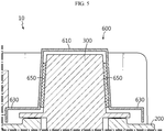
- FIG. 5 is a diagram for illustrating a terminal cover according to another embodiment, employed at the battery pack of FIG. 1 .
- the terminal cover 600 of this embodiment is similar to the terminal cover 500 of the former embodiment, and the following description will be focused on features different from the former embodiment.
- the terminal cover 600 may include a cover body 610, a detachment guide unit 630, and an elastic spacer 650.
- the cover body 610 and the detachment guide unit 630 are substantially identical or similar to the cover body 510 and the detachment guide unit 530 of the former embodiment and thus will not described in detail again.
- the elastic spacer 650 is disposed at an inner surface of the cover body 610 and may be disposed between the inner surface of the cover body 610 and the outer surface of the terminal 300 when the terminal cover 600 is mounted to the pack case 200.
- the elastic spacer 650 may be made of a rubber material with elasticity.
- the elastic spacer 650 may be made of a silicone rubber, a styrene butadiene rubber, or the like.
- the elastic spacer 650 of this embodiment is in close contact with the outer surface of the terminal 300 inside the cover body 610 and thus may more reliably prevent the terminal cover 600 from being unexpectedly released when the terminal cover 600 is mounted to the pack case 200, thereby enhancing the binding stability of the terminal cover 600.
- the terminal cover 500, 600 which may prevent the pack case 200 from being damaged due to detachment, and the battery pack 10 that including the terminal cover 500, 600.
- the terminal cover 500, 600 which allows easier detachment, and the battery pack 10 including the terminal cover 500, 600.
Landscapes
- Chemical & Material Sciences (AREA)
- Chemical Kinetics & Catalysis (AREA)
- Electrochemistry (AREA)
- General Chemical & Material Sciences (AREA)
- Battery Mounting, Suspending (AREA)
- Connection Of Batteries Or Terminals (AREA)
Abstract
Description
- The present disclosure relates to a terminal cover and a battery pack including the terminal cover.
- The present application claims priority to Korean Patent Application No.
10-2018-0007044 filed on January 19, 2018 - Secondary batteries which are highly applicable to various products and exhibit superior electrical properties such as high energy density, etc. are commonly used not only in portable devices but also in electric vehicles (EVs) or hybrid electric vehicles (HEVs) driven by electrical power sources. The secondary battery is drawing attentions as a new energy source for enhancing environment friendliness and energy efficiency in that the use of fossil fuels can be reduced greatly and no byproduct is generated during energy consumption.
- Secondary batteries widely used at present include lithium ion batteries, lithium polymer batteries, nickel cadmium batteries, nickel hydrogen batteries, nickel zinc batteries and the like. An operating voltage of the unit secondary battery cell, namely a unit battery cell, is about 2.5V to 4.6V. Therefore, if a higher output voltage is required, a plurality of battery cells may be connected in series to configure a battery pack. In addition, depending on the charge/discharge capacity required for the battery pack, a plurality of battery cells may be connected in parallel to configure a battery pack. Thus, the number of battery cells included in the battery pack may be variously set according to the required output voltage or the demanded charge/discharge capacity.
- Meanwhile, when a plurality of battery cells are connected in series or in parallel to configure a battery pack, it is common to configure a battery module composed of at least one battery cell first, and then configure a battery pack by using at least one battery module and adding other components. Here, the battery cells configuring the battery module or the battery pack are generally pouch-type secondary batteries that may be easily stacked on one another.
- A conventional battery pack includes at least one battery module including at least one battery cell, at least one terminal connected to the at least one battery module and connected to an external power source or the like, and a pack case for exposing the at least one terminal to the outside and packaging the at least one battery module. Here, the conventional battery pack generally further includes a terminal cover detachably coupled to the pack case to protect a terminal exposed to the outside when the battery pack is carried for transportation or the like. The conventional terminal cover is generally detached from the pack case according to a rotation operation performed by user manipulation.
- However, the conventional terminal cover is easily worn by the rotation according to the user manipulation, which weakens the fastening force with the pack case and damages the pack case.
- Moreover, in the case of the conventional terminal cover, it may be difficult for the user to rotate the terminal cover just by bare hands without coated gloves. That is, the conventional terminal cover may be not easily manipulated depending on the state of the hands of the user.
- Thus, it is required to provide a terminal cover, which may prevent a pack case from being damaged due to the detachment and also allow easier detachment, and a battery pack including the terminal cover.
- The present disclosure is directed to providing a terminal cover, which may prevent a pack case from being damaged due to the detachment, and a battery pack including the terminal cover.
- In addition, the present disclosure is also directed to providing a terminal cover, which may allow easier detachment, and a battery pack including the terminal cover.
- In one aspect of the present disclosure, there is provided a terminal cover, which covers a terminal of a battery pack and is detachably mounted to the battery pack, the terminal cover comprising: a cover body coupled to a pack case of the battery pack by hooking; and a detachment guide unit provided at both side surfaces of the cover body to release the hooking of the cover body according to pressing of a user.
- A hook may be provided at one side of a bottom portion of the cover body so as to be coupled to the pack case by hooking, and the detachment guide unit may be spaced apart from the hook by a predetermined distance and may be elastic deformed by the pressing of the user to separate the hook from the pack case.
- The detachment guide unit may be formed integrally with the cover body.
- The detachment guide unit may be disposed to be space apart from the pack case by a predetermined distance to form a predetermined space for the elastic deformation.
- The cover body may be made of a soft material that is elastically deformable.
- The terminal cover may further comprise an elastic spacer provided at an inner surface of the cover body and disposed between the inner surface of the cover body and an outer surface of the terminal when the terminal cover is mounted.
- In addition, the present disclosure also provides a battery pack, comprising: at least one terminal cover according to the above embodiments, at least one terminal covered by the terminal cover; a battery module electrically connected to the at least one terminal; and a pack case configured to package the battery module.
- The pack case may have a hooking portion coupled to the cover body by hooking.
- According to various embodiments as described above, it is possible to provide a terminal cover, which may prevent a pack case from being damaged due to the detachment, and a battery pack including the terminal cover.
- In addition, according to various embodiments of the present disclosure, it is possible to provide a terminal cover, which may allow easier detachment, and a battery pack including the terminal cover.
- The accompanying drawings illustrate a preferred embodiment of the present disclosure and together with the foregoing disclosure, serve to provide further understanding of the technical features of the present disclosure, and thus, the present disclosure is not construed as being limited to the drawing.
-
FIG. 1 is a diagram for illustrating a battery pack according to an embodiment of the present disclosure. -
FIG. 2 is a cross-sectional view showing main parts of the battery pack ofFIG. 1 . -
FIGS. 3 and4 are diagrams for illustrating a detachment operation of the terminal cover of the battery pack ofFIG. 1 . -
FIG. 5 is a diagram for illustrating a terminal cover according to another embodiment, employed at the battery pack ofFIG. 1 . - The present disclosure will become more apparent by describing in detail the embodiments of the present disclosure with reference to the accompanying drawings. It should be understood that the embodiments disclosed herein are illustrative only for better understanding of the present disclosure, and that the present disclosure may be modified in various ways. In addition, for ease understanding of the present disclosure, the accompanying drawings are not drawn to real scale, but the dimensions of some components may be exaggerated.
-
FIG. 1 is a diagram for illustrating a battery pack according to an embodiment of the present disclosure, andFIG. 2 is a cross-sectional view showing main parts of the battery pack ofFIG. 1 . - Referring to
FIGS. 1 and2 , abattery pack 10 may include abattery module 100, apack case 200, aterminal 300, and aterminal cover 500. - The
battery module 100 may include at least one battery cell, or a plurality of battery cells. The at least one battery cell or the plurality of battery cells may be provided as a secondary battery, for example, a pouch-type secondary battery. - At least one
battery module 100 or a plurality ofbattery modules 100 may be provided. The number ofbattery modules 100 may be determined depending on the required battery capacity. - The
pack case 200 may package thebattery module 100 and form the appearance of thebattery pack 10. Thepack case 200 may have an accommodation space for accommodating thebattery module 100. - The
pack case 200 may have ahooking portion 205. - The hooking
portion 205 is used for coupling with aterminal cover 500, explained later, and thehooking portion 205 may fix ahook 515 of theterminal cover 500, explained later, to fix theterminal cover 500 to thepack case 200. - The
terminal 300 is used for connecting thebattery module 100 to an external power source and is electrically connected to thebattery module 100. Theterminal 300 may be exposed out of thepack case 200. - The
terminal 300 may be provided in plural, and the plurality ofterminals 300 may protrude out of thepack case 200 so as to be partially exposed out of an outer surface of thepack case 200. - The
terminal cover 500 is used for protecting theterminal 300 and may cover theterminal 300 exposed out of thepack case 200. Theterminal cover 500 is mounted to thepack case 200. Here, theterminal cover 500 may be detachably mounted to thepack case 200 for the connection between theterminal 300 and the external power source. - The
terminal cover 500 may include acover body 510 and adetachment guide unit 530. - The
cover body 510 may cover theterminal 300 when theterminal cover 500 is mounted to thepack case 200. Thecover body 510 may be made of a soft material that is elastic deformable. - The
cover body 510 may be detachably coupled to thepack case 200 by hooking. - For this, the
cover body 510 may have ahook 515. - The
hook 515 is provided at one side of a bottom portion of thecover body 510 and may be detachably coupled to thepack case 200 by hooking. Specifically, thehook 515 may be detachably coupled to the hookingportion 205 of thepack case 200 by hooking. - The
detachment guide unit 530 is provided at both side surfaces of thecover body 510 and may be formed integrally with thecover body 510. In addition, thedetachment guide unit 530 may be made of the same material as thecover body 510. Accordingly, thedetachment guide unit 530 may be made of a soft material that is elastic deformable, identical to thecover body 510. - The
detachment guide unit 530 may release the hooking of thecover body 510 according to the pressing of a user. Specifically, thedetachment guide unit 530 is spaced from thehook 515 by a predetermined distance, and thedetachment guide unit 530 may be elastically deformed by the pressing of the user to separate thehook 515 from thepack case 200, thereby releasing the hooking. - The
detachment guide unit 530 may be spaced apart from thepack case 200 by a predetermined distance to facilitate the elastic deformation. Accordingly, a predetermined space S may be formed between thedetachment guide unit 530 and thepack case 200. - Hereinafter, the releasing operation of the
terminal cover 500 according to this embodiment will be described in more detail. -
FIGS. 3 and4 are diagrams for illustrating a detachment operation of the terminal cover of the battery pack ofFIG. 1 . - Referring to
FIGS. 3 and4 , when thebattery pack 10 is carried for transportation or the like, in thebattery pack 10, theterminal cover 500 may be mounted to thepack case 200 by hooking to protect theterminal 300. - After that, if the
battery pack 10 is completely carried for transportation or the like, it may be needed to detach theterminal cover 500 from thepack case 200 for the connection between the terminal 300 and an external power source. - When the
terminal cover 500 is detached, the user such as a worker may press both sides of thedetachment guide unit 530 disposed at both sides of thecover body 510 of theterminal cover 500. If thedetachment guide unit 530 disposed at both left and right sides of thecover body 510 is elastically deformed near the predetermined space S according to the pressing of the user, both upper and lower sides of thecover body 510 may also be elastically deformed in a vertical direction. - The
hook 515 of thecover body 510 is taken off from the hookingportion 205 of thepack case 200 according to the elastic deformation of thecover body 510 in the vertical direction so that the hooking between theterminal cover 500 and thepack case 200 is released. - As described above, in this embodiment, the
terminal cover 500 may be detached as the user grips thedetachment guide unit 530, rather than using the conventional rotating structure. Accordingly, in this embodiment, since an elastic force obtained by the pressing of the user is used instead of the frictional force in the conventional rotary structure, it is possible to prevent thepack case 200 from being worn or broken due to friction. - Moreover, in this embodiment, since the
terminal cover 500 is detached from thepack case 200 due to the elastic deformation caused by the pressing of the user, theterminal cover 500 may be attached or detached more easily by bare hands of the user. -
FIG. 5 is a diagram for illustrating a terminal cover according to another embodiment, employed at the battery pack ofFIG. 1 . - The
terminal cover 600 of this embodiment is similar to theterminal cover 500 of the former embodiment, and the following description will be focused on features different from the former embodiment. - Referring to
FIG. 5 , theterminal cover 600 may include acover body 610, adetachment guide unit 630, and anelastic spacer 650. - The
cover body 610 and thedetachment guide unit 630 are substantially identical or similar to thecover body 510 and thedetachment guide unit 530 of the former embodiment and thus will not described in detail again. - The
elastic spacer 650 is disposed at an inner surface of thecover body 610 and may be disposed between the inner surface of thecover body 610 and the outer surface of the terminal 300 when theterminal cover 600 is mounted to thepack case 200. - The
elastic spacer 650 may be made of a rubber material with elasticity. For example, theelastic spacer 650 may be made of a silicone rubber, a styrene butadiene rubber, or the like. - The
elastic spacer 650 of this embodiment is in close contact with the outer surface of the terminal 300 inside thecover body 610 and thus may more reliably prevent theterminal cover 600 from being unexpectedly released when theterminal cover 600 is mounted to thepack case 200, thereby enhancing the binding stability of theterminal cover 600. - According to various embodiments as described above, it is possible to provide the
terminal cover pack case 200 from being damaged due to detachment, and thebattery pack 10 that including theterminal cover - In addition, according to various embodiments of the present disclosure, it is possible to provide the
terminal cover battery pack 10 including theterminal cover - While the embodiments of the present disclosure have been shown and described, it should be understood that the present disclosure is not limited to the specific embodiments described, and that various changes and modifications can be made within the scope of the present disclosure by those skilled in the art, and these modifications should not be understood individually from the technical ideas and views of the present disclosure.
Claims (8)
- A terminal cover, which covers a terminal of a battery pack and is detachably mounted to the battery pack, the terminal cover comprising:a cover body coupled to a pack case of the battery pack by hooking; anda detachment guide unit provided at both side surfaces of the cover body to release the hooking of the cover body according to pressing of a user.
- The terminal cover according to claim 1,
wherein a hook is provided at one side of a bottom portion of the cover body so as to be coupled to the pack case by hooking, and
wherein the detachment guide unit is spaced apart from the hook by a predetermined distance and is elastic deformed by the pressing of the user to separate the hook from the pack case. - The terminal cover according to claim 2,
wherein the detachment guide unit is formed integrally with the cover body. - The terminal cover according to claim 2,
wherein the detachment guide unit is disposed to be space apart from the pack case by a predetermined distance to form a predetermined space for the elastic deformation. - The terminal cover according to claim 1,
wherein the cover body is made of a soft material that is elastically deformable. - The terminal cover according to claim 1, further comprising:
an elastic spacer provided at an inner surface of the cover body and disposed between the inner surface of the cover body and an outer surface of the terminal when the terminal cover is mounted. - A battery pack, comprising:at least one terminal cover defined in claim 1;at least one terminal covered by the terminal cover;a battery module electrically connected to the at least one terminal; anda pack case configured to package the battery module.
- The battery pack according to claim 7,
wherein the pack case has a hooking portion coupled to the cover body by hooking.
Applications Claiming Priority (2)
| Application Number | Priority Date | Filing Date | Title |
|---|---|---|---|
| KR1020180007044A KR102412941B1 (en) | 2018-01-19 | 2018-01-19 | Terminal cover and battery pack comprising the same |
| PCT/KR2019/000054 WO2019143048A1 (en) | 2018-01-19 | 2019-01-02 | Terminal cover and battery pack comprising same |
Publications (2)
| Publication Number | Publication Date |
|---|---|
| EP3664193A1 true EP3664193A1 (en) | 2020-06-10 |
| EP3664193A4 EP3664193A4 (en) | 2020-11-18 |
Family
ID=67301489
Family Applications (1)
| Application Number | Title | Priority Date | Filing Date |
|---|---|---|---|
| EP19741471.7A Pending EP3664193A4 (en) | 2018-01-19 | 2019-01-02 | TERMINAL COVER AND BATTERY PACK WITH IT |
Country Status (6)
| Country | Link |
|---|---|
| US (1) | US11757163B2 (en) |
| EP (1) | EP3664193A4 (en) |
| JP (1) | JP7045594B2 (en) |
| KR (1) | KR102412941B1 (en) |
| CN (1) | CN110710028B (en) |
| WO (1) | WO2019143048A1 (en) |
Families Citing this family (3)
| Publication number | Priority date | Publication date | Assignee | Title |
|---|---|---|---|---|
| KR102784314B1 (en) | 2020-01-06 | 2025-03-21 | 주식회사 엘지에너지솔루션 | Battery pack with improved safety and secondary battery including the same |
| KR102546117B1 (en) * | 2021-04-07 | 2023-06-22 | (주)경신전선 | Wiring jig for battery pack module |
| USD994625S1 (en) * | 2021-06-10 | 2023-08-08 | Rad Power Bikes Inc. | Terminal protector |
Family Cites Families (29)
| Publication number | Priority date | Publication date | Assignee | Title |
|---|---|---|---|---|
| KR930007539Y1 (en) | 1989-10-31 | 1993-11-03 | 금성산전 주식회사 | Circuit for lvdt output |
| DE19819365A1 (en) * | 1998-04-30 | 1999-11-04 | Techmo S A | Pole connecting clamp with protective sheath and covering for fastening device |
| JP4473361B2 (en) | 1999-03-11 | 2010-06-02 | 武内プレス工業株式会社 | Fitting structure between overcap, shoulder cover and aerosol container |
| EP1056157B1 (en) * | 1999-05-27 | 2008-01-02 | Sumitomo Wiring Systems, Ltd. | Protective cover for battery connection terminal and assembly of the protective cover and battery connection terminal |
| KR20010017452A (en) | 1999-08-11 | 2001-03-05 | 이계안 | Rocking structure between battery and cap |
| JP2001237935A (en) * | 2000-02-23 | 2001-08-31 | Mitsubishi Electric Corp | Terminal structure of portable equipment |
| JP2004119340A (en) * | 2002-09-30 | 2004-04-15 | Suzuki Motor Corp | Battery terminal cover |
| KR20040038094A (en) * | 2002-10-31 | 2004-05-08 | 현대자동차주식회사 | A cover device for terminal of battery |
| JP2006147415A (en) * | 2004-11-22 | 2006-06-08 | Daihatsu Motor Co Ltd | Battery cover |
| JP2007109577A (en) | 2005-10-14 | 2007-04-26 | Gs Yuasa Corporation:Kk | Terminal cap and battery equipped with the same |
| KR200407849Y1 (en) | 2005-11-14 | 2006-02-03 | 세방전지주식회사 | Cap for terminal protection of automotive battery |
| KR100792416B1 (en) * | 2006-09-20 | 2008-01-09 | 기아자동차주식회사 | Battery terminal connector of spring lever type |
| JP5119973B2 (en) * | 2008-02-26 | 2013-01-16 | 横河電機株式会社 | Attachment cover |
| KR101003962B1 (en) | 2010-03-15 | 2010-12-30 | 주식회사 대륙 | Circuit breaker |
| JP5244931B2 (en) * | 2011-02-22 | 2013-07-24 | 日立ビークルエナジー株式会社 | Power storage module |
| EP2501112B1 (en) * | 2011-03-14 | 2017-08-02 | LG Electronics Inc. | Locking mechanism for battery cover |
| US9147871B2 (en) * | 2011-08-01 | 2015-09-29 | Gerald A. Kowalski | Automotive battery connection system |
| JP5762228B2 (en) * | 2011-09-13 | 2015-08-12 | 矢崎総業株式会社 | In-vehicle battery assembly terminal block |
| CN102386343B (en) * | 2011-11-30 | 2013-04-24 | 江苏贝思特动力电源有限公司 | Protective cover for terminal of storage battery |
| US8703312B2 (en) * | 2011-12-23 | 2014-04-22 | Samsung Sdi Co., Ltd. | Battery module |
| KR20140063033A (en) * | 2012-11-16 | 2014-05-27 | 동아대학교 산학협력단 | Detachable plug cover |
| KR101689750B1 (en) | 2014-01-21 | 2016-12-26 | 주식회사 엘지화학 | Battery pack |
| KR101808307B1 (en) | 2014-05-28 | 2017-12-12 | 주식회사 엘지화학 | Terminal cover and battery module including the same |
| KR20160072312A (en) | 2014-12-12 | 2016-06-23 | 쌍용자동차 주식회사 | Battery cover for vehicles |
| JP6455214B2 (en) * | 2015-02-20 | 2019-01-23 | 株式会社豊田自動織機 | Power storage device protection method and power storage device |
| KR102395752B1 (en) * | 2015-08-04 | 2022-05-09 | 삼성에스디아이 주식회사 | Battery pack |
| KR102065106B1 (en) * | 2015-12-18 | 2020-01-10 | 주식회사 엘지화학 | Secondary Battery Pack |
| KR102061293B1 (en) | 2015-12-23 | 2019-12-31 | 주식회사 엘지화학 | Secondary Battery Pack |
| KR102571242B1 (en) | 2016-07-11 | 2023-08-25 | 삼성디스플레이 주식회사 | Plastic substrate with improved hardness and display device comprising the same |
-
2018
- 2018-01-19 KR KR1020180007044A patent/KR102412941B1/en active Active
-
2019
- 2019-01-02 WO PCT/KR2019/000054 patent/WO2019143048A1/en not_active Ceased
- 2019-01-02 US US16/612,151 patent/US11757163B2/en active Active
- 2019-01-02 CN CN201980002645.XA patent/CN110710028B/en active Active
- 2019-01-02 JP JP2019564801A patent/JP7045594B2/en active Active
- 2019-01-02 EP EP19741471.7A patent/EP3664193A4/en active Pending
Also Published As
| Publication number | Publication date |
|---|---|
| KR102412941B1 (en) | 2022-06-23 |
| JP2020521296A (en) | 2020-07-16 |
| JP7045594B2 (en) | 2022-04-01 |
| US11757163B2 (en) | 2023-09-12 |
| CN110710028B (en) | 2022-11-04 |
| CN110710028A (en) | 2020-01-17 |
| WO2019143048A1 (en) | 2019-07-25 |
| US20200176734A1 (en) | 2020-06-04 |
| KR20190088675A (en) | 2019-07-29 |
| EP3664193A4 (en) | 2020-11-18 |
Similar Documents
| Publication | Publication Date | Title |
|---|---|---|
| EP3836244B1 (en) | Battery module and battery pack comprising battery module | |
| US20260058262A1 (en) | Battery Cell, Battery Module Comprising Same Battery Cell, And Battery Pack Comprising Same Battery Module | |
| EP2207222B1 (en) | Battery pack | |
| US11108091B2 (en) | Battery module, and battery pack and energy storage system including the same | |
| KR102030111B1 (en) | Battery pack | |
| EP3522254B1 (en) | Battery module, battery pack including battery module, and vehicle including battery pack | |
| KR20150142338A (en) | Battery pack having bushing for coupling end plate | |
| KR20150142790A (en) | End plate for battery module assembly thereby preventing a change in the external shape of the battery module due to swelling, and battery pack having the same | |
| KR102455471B1 (en) | Battery cell, battery module comprising the battery cell, battery rack comprising the battery module and energy storage system comprising the battery rack | |
| EP4020683A1 (en) | Battery module, and battery pack and vehicle comprising battery module | |
| KR20170083311A (en) | Battery pack | |
| US11757163B2 (en) | Terminal cover and battery pack comprising same | |
| EP3392927B1 (en) | Electricity storage device | |
| CN114902470B (en) | Battery Packs, Electronics, and Vehicles | |
| CN107615518A (en) | Battery module and battery pack including the battery module | |
| EP4492551B1 (en) | Gasket for retarding flame development during thermal runaway and battery pack provided with same | |
| KR102386691B1 (en) | Battery module, battery pack and vehicle comprising the same | |
| JP5059923B2 (en) | Charger for preventing spontaneous discharge | |
| EP3624246A1 (en) | Electrode transfer device for battery cell |
Legal Events
| Date | Code | Title | Description |
|---|---|---|---|
| STAA | Information on the status of an ep patent application or granted ep patent |
Free format text: STATUS: THE INTERNATIONAL PUBLICATION HAS BEEN MADE |
|
| PUAI | Public reference made under article 153(3) epc to a published international application that has entered the european phase |
Free format text: ORIGINAL CODE: 0009012 |
|
| STAA | Information on the status of an ep patent application or granted ep patent |
Free format text: STATUS: REQUEST FOR EXAMINATION WAS MADE |
|
| 17P | Request for examination filed |
Effective date: 20200305 |
|
| AK | Designated contracting states |
Kind code of ref document: A1 Designated state(s): AL AT BE BG CH CY CZ DE DK EE ES FI FR GB GR HR HU IE IS IT LI LT LU LV MC MK MT NL NO PL PT RO RS SE SI SK SM TR |
|
| AX | Request for extension of the european patent |
Extension state: BA ME |
|
| A4 | Supplementary search report drawn up and despatched |
Effective date: 20201015 |
|
| RIC1 | Information provided on ipc code assigned before grant |
Ipc: H01M 2/30 20060101ALI20201009BHEP Ipc: H01M 2/34 20060101AFI20201009BHEP Ipc: H01R 13/46 20060101ALI20201009BHEP Ipc: H01M 2/10 20060101ALI20201009BHEP |
|
| DAV | Request for validation of the european patent (deleted) | ||
| DAX | Request for extension of the european patent (deleted) | ||
| RAP1 | Party data changed (applicant data changed or rights of an application transferred) |
Owner name: LG ENERGY SOLUTION LTD. |
|
| RAP3 | Party data changed (applicant data changed or rights of an application transferred) |
Owner name: LG ENERGY SOLUTION, LTD. |
|
| STAA | Information on the status of an ep patent application or granted ep patent |
Free format text: STATUS: EXAMINATION IS IN PROGRESS |
|
| 17Q | First examination report despatched |
Effective date: 20230510 |