EP3664003A1 - System und verfahren zum führen eines autonomen fahrzeugs - Google Patents
System und verfahren zum führen eines autonomen fahrzeugs Download PDFInfo
- Publication number
- EP3664003A1 EP3664003A1 EP19214047.3A EP19214047A EP3664003A1 EP 3664003 A1 EP3664003 A1 EP 3664003A1 EP 19214047 A EP19214047 A EP 19214047A EP 3664003 A1 EP3664003 A1 EP 3664003A1
- Authority
- EP
- European Patent Office
- Prior art keywords
- lighting device
- vehicle
- transmitter
- lighting devices
- lighting
- Prior art date
- Legal status (The legal status is an assumption and is not a legal conclusion. Google has not performed a legal analysis and makes no representation as to the accuracy of the status listed.)
- Granted
Links
Images
Classifications
-
- G—PHYSICS
- G05—CONTROLLING; REGULATING
- G05D—SYSTEMS FOR CONTROLLING OR REGULATING NON-ELECTRIC VARIABLES
- G05D1/00—Control of position, course, altitude or attitude of land, water, air or space vehicles, e.g. using automatic pilots
- G05D1/02—Control of position or course in two dimensions
- G05D1/021—Control of position or course in two dimensions specially adapted to land vehicles
- G05D1/0231—Control of position or course in two dimensions specially adapted to land vehicles using optical position detecting means
- G05D1/0242—Control of position or course in two dimensions specially adapted to land vehicles using optical position detecting means using non-visible light signals, e.g. IR or UV signals
-
- G—PHYSICS
- G05—CONTROLLING; REGULATING
- G05D—SYSTEMS FOR CONTROLLING OR REGULATING NON-ELECTRIC VARIABLES
- G05D1/00—Control of position, course, altitude or attitude of land, water, air or space vehicles, e.g. using automatic pilots
- G05D1/10—Simultaneous control of position or course in three dimensions
- G05D1/101—Simultaneous control of position or course in three dimensions specially adapted for aircraft
- G05D1/102—Simultaneous control of position or course in three dimensions specially adapted for aircraft specially adapted for vertical take-off of aircraft
-
- G—PHYSICS
- G06—COMPUTING OR CALCULATING; COUNTING
- G06Q—INFORMATION AND COMMUNICATION TECHNOLOGY [ICT] SPECIALLY ADAPTED FOR ADMINISTRATIVE, COMMERCIAL, FINANCIAL, MANAGERIAL OR SUPERVISORY PURPOSES; SYSTEMS OR METHODS SPECIALLY ADAPTED FOR ADMINISTRATIVE, COMMERCIAL, FINANCIAL, MANAGERIAL OR SUPERVISORY PURPOSES, NOT OTHERWISE PROVIDED FOR
- G06Q10/00—Administration; Management
- G06Q10/08—Logistics, e.g. warehousing, loading or distribution; Inventory or stock management
-
- G—PHYSICS
- G06—COMPUTING OR CALCULATING; COUNTING
- G06Q—INFORMATION AND COMMUNICATION TECHNOLOGY [ICT] SPECIALLY ADAPTED FOR ADMINISTRATIVE, COMMERCIAL, FINANCIAL, MANAGERIAL OR SUPERVISORY PURPOSES; SYSTEMS OR METHODS SPECIALLY ADAPTED FOR ADMINISTRATIVE, COMMERCIAL, FINANCIAL, MANAGERIAL OR SUPERVISORY PURPOSES, NOT OTHERWISE PROVIDED FOR
- G06Q50/00—Information and communication technology [ICT] specially adapted for implementation of business processes of specific business sectors, e.g. utilities or tourism
- G06Q50/40—Business processes related to the transportation industry
-
- H—ELECTRICITY
- H05—ELECTRIC TECHNIQUES NOT OTHERWISE PROVIDED FOR
- H05B—ELECTRIC HEATING; ELECTRIC LIGHT SOURCES NOT OTHERWISE PROVIDED FOR; CIRCUIT ARRANGEMENTS FOR ELECTRIC LIGHT SOURCES, IN GENERAL
- H05B47/00—Circuit arrangements for operating light sources in general, i.e. where the type of light source is not relevant
- H05B47/10—Controlling the light source
- H05B47/165—Controlling the light source following a pre-assigned programmed sequence; Logic control [LC]
-
- B—PERFORMING OPERATIONS; TRANSPORTING
- B64—AIRCRAFT; AVIATION; COSMONAUTICS
- B64U—UNMANNED AERIAL VEHICLES [UAV]; EQUIPMENT THEREFOR
- B64U2201/00—UAVs characterised by their flight controls
Definitions
- the present invention relates to a system and a method for driving an autonomous vehicle.
- autonomous vehicles such as Drones or cleaning robots can be used. It is known that e.g. autonomous cleaning robots can move along random routes through buildings and often also achieve satisfactory cleaning results. However, it is often desirable for the autonomous vehicle to move along a predetermined route in order to avoid unnecessary detours or to ensure that all locations along the route are actually visited.
- Radio LiDAR or camera-based systems
- a complex infrastructure must be created.
- the accuracy is often not sufficient.
- Camera-based systems are complex and have no 3D information about the location.
- active optical systems such as IR LED scanners or LiDAR systems must be used.
- LiDAR systems and camera systems are complex, expensive and consume a lot of electrical energy and cannot provide targeted route planning
- the object of the present invention is to provide a system and a method for driving an autonomous vehicle which solves one or more of the above-mentioned problems from the prior art.
- a special feature of the system according to the present invention is that the lighting devices are not only used for lighting, but also for sending out guide signals which can guide the autonomous vehicle from one lighting device to the next. The vehicle can thus be guided via the lighting devices.
- the transmitters of the lighting devices can preferably be arranged directly next to the illuminants of the lighting devices.
- the receivers of the lighting devices can be arranged next to the lighting means, in particular directly next to the lighting devices.
- the transmitters are still arranged within the lighting devices.
- the transmitter is preferably integrated within the lighting device in such a way that optics can be used both for the lighting and for the transmitter for transmitting the guidance signal.
- the lighting devices can be networked with one another via a cable-based network, e.g. a bus system, or by radio, e.g. via IEEE 802.11 or Bluetooth.
- the bus system can be part of a building management system for the entire building.
- the networking takes place via a light management system, which is responsible for the control and management of the lighting devices in a building.
- the vehicle is a drone. Since the lighting devices are usually arranged elevated, they are particularly suitable for guiding drones. The drones preferably use a flight height that corresponds approximately to a height of the arrangement of the lighting devices.
- the first and the second lighting device are permanently installed, in particular are part of a building installation.
- the lighting devices can be arranged on the ceiling of a room or on storage shelves.
- the plurality of lighting devices include the first and second lighting devices.
- the plurality of lighting devices preferably comprises a total of at least 10, in particular at least 50, lighting devices.
- the plurality of lighting devices can be arranged as a light band system.
- the lighting devices can be installed inside or outside of a building.
- the system can also be used outdoors.
- All of the lighting devices of the plurality of lighting devices are preferably permanently installed.
- the lighting devices have sensors in order to determine their own position.
- these can be GPS and / or Galileo sensors.
- the first lighting device furthermore has a first receiver for receiving a location signal of the vehicle and the second lighting device furthermore has a second receiver for receiving a location signal of the vehicle.
- the lighting devices can thus detect where the autonomous vehicle is currently located. For example, it can be provided that the second guidance signal is switched off when the vehicle has reached the second lighting device.
- the fact that the vehicle has reached the second lighting device can be recognized, for example, when a signal measured by the second receiver has exceeded a predetermined threshold value.
- the lighting devices can be designed to pass the information about the measured location signals over the network to other lighting devices.
- the first transmitter and a light source of the first lighting device are arranged such that the guide signal sent by the first transmitter and light emitted by the light source are spatially distributed by common optics, in particular a reflector and / or a lens will.
- This embodiment has the advantage that the optics of the lighting device (which are present anyway) (for distributing the light from an illuminant of the lighting device) can also be used for distributing the control signal.
- Modern lighting devices typically have complex optics in order to be able to distribute the light evenly over a target region. According to the embodiment, this optic can then also be used for the uniform distribution of the guidance signal.
- the controller is designed to control the plurality of lighting devices in such a way that only one transmitter from one lighting device is active at any one time. This ensures that the autonomous vehicle is only ever led to the lighting device that is to be controlled next.
- the lighting devices are preferably controlled by a central control device, wherein the central control device may have stored a route.
- the first and the second transmitter are configured to emit frequency-modulated light.
- different commands can be sent to the vehicle via different frequencies of the guidance signal.
- a certain frequency can encode a stop signal so that, for example, a drone can be stopped immediately in an emergency.
- the first and the second transmitter comprise infrared light-emitting diodes.
- Infrared light-emitting diodes are small, inexpensive, long-lasting and have sufficient transmission power to reliably control the vehicle.
- the infrared light-emitting diode is preferably arranged next to the illuminant of the lighting device.
- the infrared light emitting diode can be arranged directly next to the illuminant. Possibly. Suitable measures for heat dissipation must be taken so that the heat of the illuminant does not lead to overheating of the infrared light emitting diode.
- the first and the second transmitter are designed to emit signals with different wavelengths and / or different frequency modulation. Different vehicles can thus be controlled differently. For example, a first vehicle can be driven to follow a first route and a second vehicle can be driven to follow a second route.
- the multiplicity of lighting devices comprise a multiplicity of receivers which are designed to receive location signals transmitted by the vehicle, and a recording device which is designed to determine a route from the received locating signals.
- the route can be determined by a user running the route once on foot and carrying a transmitter for the location signal.
- the location signals are received and recorded by the receivers of the lighting devices. From the sequence of when which receiver receives the location signal, the sequence of the guidance signals to be transmitted can then be determined in accordance with this route.
- the system is designed to receive a flight plan via a network, in particular a radio network.
- the networked lighting devices can be networked with a control unit, the control unit including an input device for entering and displaying a route.
- the first and the second transmitter are designed to transmit a guidance signal with a first coding and a guidance signal with a second coding, which is different from the first coding.
- Such codes can be used to control different vehicles on different routes or to send certain commands to the vehicles.
- Instructions that, when executed by a processor, perform the steps of the above method can be stored on a data carrier.
- the method further comprises detecting a route along the plurality of lighting devices in that, while the autonomous vehicle is moving along the route, a location signal emitted by the autonomous vehicle and received by receivers of the plurality of lighting devices is recorded.
- the autonomous vehicle can be a drone, i.e. an unmanned aerial vehicle or a cleaning robot.
- the autonomous vehicle can have one or more transmitters that are designed to transmit the location signal.
- the autonomous vehicle can have one or more receivers which are designed to receive the guidance signals.
- the autonomous vehicle can be part of one of the above systems. It goes without saying that the transmitter of the vehicle is preferably designed such that its location signal can be received by the receivers of the lighting devices.
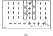
- FIG. 1 shows an arrangement for guiding a drone 10 through a room in a room 20 of a building.
- the arrangement comprises a plurality of lighting devices 1-8 which have transmitters for emitting a guidance signal.
- the guidance begins in that a guidance signal, for example in the infrared range, is output on the lighting device 1.
- This guidance signal is received by the drone 10.
- the drone 10 then flies towards the command signal. If the drone 10 is located at the lighting device 1, this transmission signal is switched off and the lighting device 2 begins to transmit.
- the guide runs accordingly to the lighting device 8, with which the drone has reached the end point of route 12.
- In the room 20 there are further lighting devices 9, which are not involved in guiding the drone 10 on this route 12.
- the drone can be guided along the predefined route 12, for example between the storage racks 22.
- a room in a building instead of a room in a building, it can also be an outdoor room.
- the transmission level and reception level can be located within the luminaire.
- the transmission stage of the luminaire sends a signal, for example through IR LED transmit diodes.
- the reception level reacts to the location signals from the drone.
- the lighting cover the luminaire ensures the desired expansion of the guidance signal.
- the drone If the drone is in the area of the lamp, this is detected by the increase in the reception amplitude within the lamp.
- This information is processed via an intelligent networked system, so that this lamp switches off the transmission of the command signal and the next lamp activates the transmission of the command signal.
- There is a transmission and reception stage in the drone which is designed in accordance with that of the lamp. This means that the transmission stage of the drone is designed to transmit on a frequency that is received by the receiver of the lamp and the transmitter of the lamp is designed to transmit on a frequency that is received by the reception stage of the drone.
- the drone preferably knows a specific frequency modulation of the lights and can process this signal. With this frequency-modulated, unique signal in each lamp, a drone can be guided quickly and easily through a building by following the light signals of the respective lamp. The lights indicate the direction of movement for the drone. The drone follows these light signals to the target. Several drones can also be guided to the destination via signal variants of the transmitter LEDs.
Landscapes
- Engineering & Computer Science (AREA)
- Physics & Mathematics (AREA)
- Business, Economics & Management (AREA)
- General Physics & Mathematics (AREA)
- Economics (AREA)
- General Business, Economics & Management (AREA)
- Theoretical Computer Science (AREA)
- Automation & Control Theory (AREA)
- Remote Sensing (AREA)
- Strategic Management (AREA)
- Tourism & Hospitality (AREA)
- Human Resources & Organizations (AREA)
- Radar, Positioning & Navigation (AREA)
- Aviation & Aerospace Engineering (AREA)
- Marketing (AREA)
- Electromagnetism (AREA)
- Development Economics (AREA)
- Entrepreneurship & Innovation (AREA)
- Quality & Reliability (AREA)
- Operations Research (AREA)
- Health & Medical Sciences (AREA)
- General Health & Medical Sciences (AREA)
- Primary Health Care (AREA)
- Circuit Arrangement For Electric Light Sources In General (AREA)
- Traffic Control Systems (AREA)
Abstract
Description
- Die vorliegende Erfindung betrifft ein System und ein Verfahren zum Führen eines autonomen Fahrzeugs.
- Für die Wartung oder Überwachung von Gebäuden, zum Beispiel zum Reinigen der Böden oder für die Überwachung von Gegenständen in Regalen, können autonome Fahrzeuge wie z.B. Drohnen oder Putzroboter eingesetzt werden. Es ist bekannt, dass z.B. autonome Putzroboter sich entlang zufälliger Routen durch Gebäude bewegen können und hierbei oft auch zufriedenstellende Putzergebnisse erzielt werden können. Häufig ist es aber wünschenswert, dass das autonomen Fahrzeug sich entlang einer vorbestimmten Routen bewegen, um unnötige Umwege zu vermeiden, oder um sicherzustellen, dass alle Orte entlang der Route auch tatsächlich besucht werden.
- Bekannt ist aus dem Stand der Technik, Funk, LiDAR oder Kamerabasierte Systeme zu verwenden um ein autonomes Fahrzeug entlang einer Route zu steuern. Im Falle der Funkführung muss eine aufwendige Infrastruktur erstellt werden. Die Genauigkeit ist dabei dennoch oft nicht ausreichend. Kamerabasierte Systeme sind aufwendig und haben keine 3D-Information der Örtlichkeiten. Um 3D-Informationen zu erlangen müssen aktive Optische Systeme wie IR LED Scanner oder LiDAR Systeme verwendet werden. LiDAR-systeme, sowie Kamerasysteme sind aufwendig, teuer und verbrauchen viel elektrische Energie und können keine gezielte Routenplanung bereitstellen
- Aufgabe der vorliegenden Erfindung ist es, ein System und ein Verfahren zum Führen eines autonomen Fahrzeugs bereitzustellen, dass eine oder mehrere der oben genannten Probleme aus dem Stand der Technik löst.
- Gelöst wird die Aufgabe durch ein System nach Anspruch 1.
- Insbesondere wird ein System zum Führen eines autonomen Fahrzeugs mit einer Vielzahl von vernetzten Beleuchtungsvorrichtungen bereitgestellt. Das System umfasst:
- eine erste Beleuchtungsvorrichtung mit einem ersten Sender zum Senden eines ersten Führsignals zum Führen des Fahrzeugs,
- eine zweite Beleuchtungsvorrichtung mit einem zweiten Sender zum Senden eines zweiten Führsignals zum Führen des Fahrzeugs, und
- eine Steuerung, die dazu ausgebildet ist, den ersten und den zweiten Sender so anzusteuern, dass das Fahrzeug von der ersten zu der zweiten Beleuchtungsvorrichtung geführt wird.
- Eine Besonderheit des Systems gemäß der vorliegenden Erfindung besteht darin, dass die Beleuchtungsvorrichtungen nicht nur zur Beleuchtung verwendet werden, sondern darüber hinaus auch zum Aussenden von Führsignalen, die das autonome Fahrzeug von einer Beleuchtungsvorrichtung zur nächsten führen können. Somit kann also die Führung des Fahrzeugs über die Beleuchtungsvorrichtungen erfolgen.
- Die Sender der Beleuchtungsvorrichtungen können vorzugsweise unmittelbar neben den Leuchtmitteln der Beleuchtungsvorrichtungen angeordnet sein. Ebenso können die Empfänger der Beleuchtungsvorrichtungen neben den Leuchtmitteln, insbesondere unmittelbar neben den Beleuchtungsvorrichtungen, angeordnet sein. Dabei sind die Sender aber immer noch innerhalb der Beleuchtungsvorrichtungen angeordnet. Vorzugsweise ist dabei der Sender so innerhalb der Beleuchtungsvorrichtung integriert, dass eine Optik sowohl für die Beleuchtung als auch für den Sender zum Senden des Führsignals verwendet werden kann.
- Die Vernetzung der Beleuchtungsvorrichtungen untereinander kann über ein kabelbasiertes Netzwerk, z.B. ein Bus-System, oder per Funk, z.B. per IEEE 802.11 oder Bluetooth, erfolgen. Das Bus-System kann Teil eines Building Management Systems für das ganze Gebäude sein. In anderen Ausführungsformen erfolgt die Vernetzung über eine Light Management System, das für die Ansteuerung und Verwaltung der Beleuchtungsvorrichtungen in einem Gebäude zuständig ist.
- Gemäß einer bevorzugten Ausführungsform ist das Fahrzeug eine Drohne. Da die Beleuchtungsvorrichtungen üblicherweise erhöht angeordnet sind, sind sie besonders geeignet, um Drohnen zu führen. Vorzugsweise verwenden die Drohnen dabei eine Flughöhe, die ungefähr einer Höhe der Anordnung der Beleuchtungsvorrichtungen entspricht.
- Gemäß einer bevorzugten Ausführungsform ist vorgesehen, dass die erste und die zweite Beleuchtungsvorrichtung fest installiert sind, insbesondere Teil einer Gebäudeinstallation sind. Zum Beispiel können die Beleuchtungsvorrichtungen an der Decke eines Raumes oder an Lagerregalen angeordnet sein.
- Die Vielzahl von Beleuchtungsvorrichtungen umfasst die erste und die zweite Beleuchtungsvorrichtung. Vorzugsweise umfasst die Vielzahl von Beleuchtungsvorrichtungen insgesamt mindestens 10, insbesondere mindestens 50 Beleuchtungsvorrichtungen.
- Die Vielzahl von Beleuchtungsvorrichtungen kann als Lichtbandsystem angeordnet sein.
- Dies hat den Vorteil, dass die Position der Beleuchtungsvorrichtungen unveränderlich ist, und somit nur einmal eine Route entlang der Beleuchtungsvorrichtungen bestimmt werden muss.
- Die Beleuchtungsvorrichtungen können im Innenraum oder in einem Außenraumen eines Gebäudes installiert werden. Insbesondere kann das System also auch im Außenbereich zum Einsatz kommen.
- Vorzugsweise sind alle Beleuchtungsvorrichtungen der Vielzahl von Beleuchtungsvorrichtungen fest installiert.
- In Ausführungsformen kann vorgesehen sein, dass die Beleuchtungsvorrichtungen Sensoren aufweisen, um ihre eigene Position zu bestimmen. Zum Beispiel können dies GPS- und/oder Galileo-Sensoren sein.
- Gemäß einer bevorzugten Ausführungsform ist vorgesehen, dass die erste Beleuchtungsvorrichtung weiterhin einen ersten Empfänger zum Empfangen eines Ortungssignals des Fahrzeugs und die zweite Beleuchtungsvorrichtung weiterhin einen zweiten Empfänger zum Empfangen eines Ortungssignals des Fahrzeugs aufweist.
- Somit können die Beleuchtungsvorrichtungen erfassen, wo sich das autonome Fahrzeug gerade befindet. Zum Beispiel kann vorgesehen sein, dass das zweite Führsignal dann abgeschaltet wird, wenn das Fahrzeug die zweite Beleuchtungsvorrichtung erreicht hat. Dass das Fahrzeug die zweite Beleuchtungsvorrichtung erreicht hat, kann z.B. erkannt werden, wenn ein von dem zweiten Empfänger gemessenes Signal einen vorbestimmten Schwellenwert überschritten hat.
- Die Beleuchtungsvorrichtungen können dazu ausgebildet sein, die Information über die gemessenen Ortungssignale über das Netzwerk zu anderen Beleuchtungsvorrichtungen weiterzuleiten.
- Gemäß einer bevorzugten Ausführungsform ist vorgesehen, dass der erste Sender und ein Leuchtmittel der ersten Beleuchtungsvorrichtung so angeordnet sind, dass das vom ersten Sender gesendete Führsignal und von dem Leuchtmittel emittiertes Licht durch eine gemeinsame Optik, insbesondere einen Reflektor und/oder eine Linse, räumlich verteilt werden.
- Diese Ausführungsform hat den Vorteil, dass die sowieso vorhandene Optik der Beleuchtungsvorrichtung (zum Verteilen des Lichts von einem Leuchtmittel der Beleuchtungsvorrichtung) auch zur Verteilung des Führsignals verwendet werden kann. Moderne Beleuchtungsvorrichtungen haben typischerweise eine aufwendige Optik, um das Licht gleichmäßig auf eine Zielregion verteilen zu können. Diese Optik kann gemäß der Ausführungsform dann auch zur gleichmäßigen Verteilung des Führsignals verwendet werden.
- Gemäß einer bevorzugten Ausführungsform ist vorgesehen, dass die Steuerung dazu ausgebildet ist, die Vielzahl von Beleuchtungsvorrichtungen so anzusteuern, dass zu jedem Zeitpunkt nur ein Sender von einer Beleuchtungsvorrichtung aktiv ist. Somit ist sichergestellt, dass das autonome Fahrzeug immer nur zu der Beleuchtungsvorrichtung hingeführt wird, die als nächstes angesteuert werden soll. Vorzugsweise werden die Beleuchtungsvorrichtungen von einer zentralen Steuervorrichtung angesteuert, wobei die zentrale Steuervorrichtung eine Route gespeichert haben kann.
- Gemäß einer bevorzugten Ausführungsform ist vorgesehen, dass der erste und der zweite Sender konfiguriert sind, um frequenzmoduliertes Licht auszusenden. Zumindest Beispiel können über unterschiedliche Frequenzen des Führsignals unterschiedliche Befehle an das Fahrzeug gesendet werden. Zum Beispiel kann eine bestimme Frequenz ein Stoppsignal kodieren, so dass zum Beispiel in einem Notfall eine Drohne sofort gestoppt werden kann.
- Gemäß einer bevorzugten Ausführungsform ist vorgesehen, dass der erste und der zweite Sender Infrarot-Leuchtdioden umfassen. Infrarot-Leuchtdioden sind klein, kostengünstig, langlebig und von ausreichender Sendleistung, um das Fahrzeug zuverlässig anzusteuern. Vorzugsweise wird die Infrarot-Leuchtdiode neben dem Leuchtmittel der Beleuchtungsvorrichtung angeordnet. Zum Beispiel kann die Infrarot-Leuchtiode unmittelbar neben dem Leuchtmittel angeordnet sein. Ggf. müssen geeignete Maßnahmen zur Wärmeableitung getroffen werden, damit die Wärme des Leuchtmittels nicht zu einer Überhitzung der Infrarot-Leuchtdiode führt.
- Gemäß einer bevorzugten Ausführungsform ist vorgesehen, dass der erste und der zweite Sender dazu ausgebildet sind, Signale mit unterschiedlicher Wellenlänge und/oder unterschiedlicher Frequenzmodulation auszusenden. Somit können unterschiedliche Fahrzeuge unterschiedlich angesteuert werden. Zum Beispiel kann ein erstes Fahrzeug angesteuert werden, um einer ersten Route zu folgen und ein zweites Fahrzeug kann angesteuert werden, um einer zweiten Route zu folgen.
- Gemäß einer bevorzugten Ausführungsform ist vorgesehen, dass die Vielzahl von Beleuchtungsvorrichtungen eine Vielzahl von Empfängern umfasst, die dazu ausgebildet sind, von dem Fahrzeug ausgesendete Ortungssignale zu empfangen, sowie eine Aufzeichnungsvorrichtung, die dazu ausgebildet ist, aus den empfangenen Ortungssignalen eine Route zu bestimmen.
- Somit kann zum Beispiel die Route dadurch festgelegt werden, dass ein Benutzer die Route einmal zu Fuß abläuft und dabei einen Sender für das Ortungssignal mit sich führt. Die Ortungssignale werden von den Empfängern der Beleuchtungsvorrichtungen empfangen und aufgezeichnet. Aus der Abfolge, wann welcher Empfänger das Ortungssignal empfängt, kann dann die Abfolge der auszusendenden Führsignale gemäß dieser Route bestimmt werden.
- Gemäß einer bevorzugten Ausführungsform ist vorgesehen, dass das System dazu ausgebildet ist, einen Flugplan über ein Netzwerk, insbesondere ein Funk-Netzwerk, zu empfangen. Zum Beispiel können die vernetzten Beleuchtungsvorrichtungen mit einer Steuereinheit vernetzt sein, wobei die Steuereinheit eine Eingabevorrichtung zum Eingeben und Darstellen einer Route beinhaltet.
- Gemäß einer bevorzugten Ausführungsform ist vorgesehen, dass der erste und der zweite Sender ausgebildet sind, ein Führsignal mit einer ersten Codierung und ein Führsignal mit einer zweiten Codierung, das von der ersten Codierung verschieden ist, zu senden. Derartige Codierungen können verwendet werden, um unterschiedliche Fahrzeuge auf unterschiedliche Routen zu steuern, oder um bestimmte Kommandos an die Fahrzeuge zu senden.
- Gemäß einem weiteren Aspekt der vorliegenden Erfindung wird ein Verfahren zum Führen eines autonomen Fahrzeugs mit einer Vielzahl von Beleuchtungsvorrichtungen bereitgestellt. Das Verfahren umfasst die Schritte:
- Senden, von einer ersten Beleuchtungsvorrichtung, eines ersten Führsignals zum Führen des Fahrzeugs zu der ersten Beleuchtungsvorrichtung, und
- Senden, von einer zweiten Beleuchtungsvorrichtung, eines zweiten Führsignals zum Führen des Fahrzeugs zu der zweiten Beleuchtungsvorrichtung.
- Anweisungen, die, wenn sie von einem Prozessor ausgeführt werden, die Schritte des oben genannten Verfahrens ausführen, können auf einem Datenträger gespeichert werden.
- Gemäß einer bevorzugten Ausführungsform ist vorgesehen, dass das Verfahren weiterhin umfasst, eine Route entlang der Vielzahl von Beleuchtungsvorrichtungen zu erfassen, indem, während sich das autonome Fahrzeug entlang der Route bewegt, ein von dem autonomen Fahrzeug emittiertes und von Empfängern der Vielzahl von Beleuchtungsvorrichtungen empfangenes Ortungssignal aufgezeichnet wird.
- Ein weiterer Aspekt der Erfindung bezieht sich auf ein autonomes Fahrzeug, das dazu ausgebildet ist durch ein Verfahren gemäß einem der Ansprüche 13 und 14 entlang einer Route geführt zu werden. Zum Beispiel kann es sich bei dem autonomen Fahrzeug um eine Drohne, d.h. ein unbemannte Luftfahrzeug oder um einen Putzroboter handeln. Das autonome Fahrzeug kann ein oder mehrere Sender aufweisen, die dazu ausgebildet sind, das Ortungssignal auszusenden. Weiterhin kann das autonome Fahrzeug ein oder mehrere Empfänger aufweisen, die dazu ausgebildet sind, die Führsignale zu empfangen.
- Das autonome Fahrzeug kann Bestandteil eines der obengenannten Systeme sein. Es versteht sich, dass dabei der Sender des Fahrzeugs vorzugsweise so ausgebildet ist, dass sein Ortungssignal von den Empfängern der Beleuchtungsvorrichtungen empfangen werden kann.
- Weitere Merkmale und Vorteile der vorliegenden Erfindung werden aus der nachfolgenden detaillierten Beschreibung einer Ausführungsform deutlich, welche in Bezug auf die beigefügte Figur gegeben wird.
-
FIG. 1 zeigt eine Anordnung zum Führen einer Drohne 10 durch einen Raum in einem Raum 20 eines Gebäudes. Die Anordnung umfasst eine Vielzahl von Beleuchtungsvorrichtungen 1-8, die Sender zum Aussenden eines Führsignals aufweisen. Die Führung beginnt, indem an der Beleuchtungsvorrichtung 1 ein Führsignal, z.B. im Infrarotbereich, ausgegeben wird. Dieses Führsignal wird von der Drohne 10 empfangen. Die Drohne 10 fliegt daraufhin auf das Führsignal zu. Befindet sich die Drohne 10 bei der Beleuchtungsvorrichtung 1, wird dieses Sendesignal abgeschaltet und die Beleuchtungsvorrichtung 2 beginnt zu senden. Die Führung verläuft entsprechend bis zur Beleuchtungsvorrichtung 8, womit die Drohne den Endpunkt der Route 12 erreicht hat. In dem Raum 20 befinden sich weitere Beleuchtungsvorrichtungen 9, die bei der Führung der Drohne 10 auf dieser Route 12 nicht involviert sind. Weiterhin befinden sich in dem Raum 10 Lagerregale 22. Die Drohne kann auf der vorgegebenen Route 12 z.B. zwischen den Lagerregalen 22 geführt werden. - In anderen Ausführungsformen kann es sich statt um einen Raum in einem Gebäude auch um einen Raum im Freien handeln.
- Bei der Anordnung gemäß
FIG. 1 erfolgt also eine Integration der Drohnenführung innerhalb einer Leuchte. Hierbei können sich Sendestufe und Empfangsstufe innerhalb der Leuchte befinden. Die Sendestufe der Leuchte sendet ein Signal, z.B. durch IR LED Sendedioden aus. Die Empfangsstufe reagiert auf die Ortungssignale der Drohne. Die lichttechnische Abdeckung der Leuchte sorgt für eine gewünschte Aufweitung des Führsignals. - Befindet sich die Drohne im Bereich der Leuchte wird dies durch den Anstieg der Empfangsamplitude innerhalb der Leuchte detektiert. Über ein intelligentes vernetztes System wird diese Information verarbeitet, so dass diese Leuchte das Senden des Führsignals abschaltet und die nächste Leuchte das Aussenden des Führsignals aktiviert. In der Drohne befindet sich eine Sende und Empfangsstufe, welche entsprechend zu der der Leuchte ausgebildet ist. Das bedeutet, die Sendestufe der Drohne ist ausgebildet, um auf einer Frequenz zu senden, die von dem Empfänger der Leuchte empfangen wird und der Sender der Leuchte ist ausgebildet, auf einer Frequenz zu senden, die von der Empfangsstufe der Drohne empfangen wird.
- Vorzugsweise kennt die Drohne kennt eine spezifische Frequenzmodulation der Leuchten und kann dieses Signal verarbeiten. Durch dieses frequenzmodulierte eindeutige Signal in jeder Leuchte kann eine Drohne schnell und einfach durch ein Gebäude geleitet werden, indem sie den Lichtsignalen der jeweiligen Leuchte folgt. Die Leuchten geben die Bewegungsrichtung für die Drohne vor. Die Drohne folgt diesen Lichtsignalen bis zum Ziel. Über Signalvarianten der Sende-LEDs lassen sich auch mehrere Drohnen ins Ziel führen.
-
- 1-9
- Beleuchtungsvorrichtung
- 10
- Drohne
- 12
- Route
- 20
- Raum
- 22
- Lagerregal
Claims (15)
- System zum Führen eines autonomen Fahrzeugs (10) mit einer Vielzahl von vernetzten Beleuchtungsvorrichtungen (1-9), umfassend:eine erste Beleuchtungsvorrichtung (1-9) mit einem ersten Sender zum Senden eines ersten Führsignals zum Führen des Fahrzeugs,eine zweite Beleuchtungsvorrichtung (1-9) mit einem zweiten Sender zum Senden eines zweiten Führsignals zum Führen des Fahrzeugs, undeine Steuerung, die dazu ausgebildet ist, den ersten und den zweiten Sender so anzusteuern, dass das Fahrzeug von der ersten zu der zweiten Beleuchtungsvorrichtung geführt wird.
- System nach Anspruch 1, wobei das Fahrzeug (10) eine Drohne ist.
- System nach einem der vorherigen Ansprüche, wobei die erste und die zweite Beleuchtungsvorrichtung (1-9) fest installiert sind, insbesondere Teil einer Gebäudeinstallation sind.
- System nach einem der vorherigen Ansprüche, wobei die erste Beleuchtungsvorrichtung (1-9) weiterhin einen ersten Empfänger zum Empfangen eines Ortungssignal des Fahrzeugs und die zweite Beleuchtungsvorrichtung (1-9) weiterhin einen zweiten Empfänger zum Empfangen eines Ortungssignals des Fahrzeugs (10) aufweist.
- System nach einem der vorherigen Ansprüche, wobei der erste Sender und ein Leuchtmittel der ersten Beleuchtungsvorrichtung (1-9) so angeordnet sind, dass das vom ersten Sender gesendete Führsignal und von dem Leuchtmittel emittiertes Licht durch eine gemeinsame Optik, insbesondere einen Reflektor oder eine Linse, räumlich verteilt werden.
- System nach einem der vorherigen Ansprüche, wobei die Steuerung dazu ausgebildet ist, die Vielzahl von Beleuchtungsvorrichtungen (1-9) so anzusteuern, dass zu jedem Zeitpunkt nur ein Sender von einer Beleuchtungsvorrichtung aktiv ist.
- System nach einem der vorherigen Ansprüche, wobei der erste und der zweite Sender konfiguriert sind, um frequenzmoduliertes Licht auszusenden.
- System nach einem der vorherigen Ansprüche, wobei der erste Sender eine Infrarot-Leuchtdiode umfasst, wobei die erste Infrarot-Leuchtdiode vorzugsweise neben einem Leuchtmittel der ersten Beleuchtungsvorrichtung (1-9) angeordnet ist.
- System nach einem der vorherigen Ansprüche, wobei der erste und der zweite Sender dazu ausgebildet sind, Signale mit unterschiedlicher Wellenlänge und/oder unterschiedlicher Frequenzmodulation auszusenden.
- System nach einem der vorherigen Ansprüche, wobei die Vielzahl von Beleuchtungsvorrichtungen (1-9) eine Vielzahl von Empfängern umfasst, die dazu ausgebildet sind, von dem Fahrzeug (10) ausgesendete Ortungssignale zu empfangen, sowie eine Aufzeichnungsvorrichtung, die dazu ausgebildet ist, aus den empfangenen Ortungssignalen eine Route (12) zu bestimmen.
- System nach einem der vorherigen Ansprüche, wobei das System dazu ausgebildet ist, eine Route über ein Netzwerk, insbesondere ein Funk-Netzwerk, zu empfangen.
- System nach einem der vorherigen Ansprüche, wobei der erste und der zweite Sender ausgebildet sind, ein Führsignal mit einer ersten Codierung und ein Führsignal mit einer zweiten Codierung, das von der ersten Codierung verschieden ist, zu senden.
- Verfahren zum Führen eines autonomen Fahrzeugs (10) mit einer Vielzahl von vernetzten Beleuchtungsvorrichtungen (1-9), umfassend:- Senden, von einer ersten Beleuchtungsvorrichtung, eines ersten Führsignals zum Führen des Fahrzeugs (10) zu der ersten Beleuchtungsvorrichtung,- Senden, von einer zweiten Beleuchtungsvorrichtung, eines zweiten Führsignals zum Führen des Fahrzeugs zu der zweiten Beleuchtungsvorrichtung.
- Verfahren nach Anspruch 13, wobei das Verfahren weiterhin umfasst, eine Route (12) entlang der Vielzahl von Beleuchtungsvorrichtungen (1-9) zu erfassen, indem, während sich das autonome Fahrzeug entlang der Route bewegt, ein von dem autonomen Fahrzeug emittiertes und von Empfängern der Vielzahl von Beleuchtungsvorrichtungen empfangenes Ortungssignal aufgezeichnet wird.
- Autonomes Fahrzeug (10), dazu ausgebildet durch ein Verfahren gemäß einem der Ansprüche 13 und 14 entlang einer Route (12) geführt zu werden.
Applications Claiming Priority (2)
| Application Number | Priority Date | Filing Date | Title |
|---|---|---|---|
| DE102018009603 | 2018-12-06 | ||
| DE102019105159.2A DE102019105159A1 (de) | 2018-12-06 | 2019-02-28 | System und verfahren zum führen eines autonomen fahrzeugs |
Publications (2)
| Publication Number | Publication Date |
|---|---|
| EP3664003A1 true EP3664003A1 (de) | 2020-06-10 |
| EP3664003B1 EP3664003B1 (de) | 2022-09-21 |
Family
ID=68808123
Family Applications (1)
| Application Number | Title | Priority Date | Filing Date |
|---|---|---|---|
| EP19214047.3A Active EP3664003B1 (de) | 2018-12-06 | 2019-12-06 | System und verfahren zum führen eines autonomen fahrzeugs |
Country Status (1)
| Country | Link |
|---|---|
| EP (1) | EP3664003B1 (de) |
Citations (2)
| Publication number | Priority date | Publication date | Assignee | Title |
|---|---|---|---|---|
| WO2015036912A1 (en) * | 2013-09-10 | 2015-03-19 | Koninklijke Philips N.V. | Methods and apparatus for automated commissioning of coded light sources |
| US20160054130A1 (en) * | 2014-08-22 | 2016-02-25 | Verizon Patent And Licensing Inc. | Apparatus, method, and system for providing beacon-based navigation |
Family Cites Families (2)
| Publication number | Priority date | Publication date | Assignee | Title |
|---|---|---|---|---|
| US6400482B1 (en) * | 1998-04-15 | 2002-06-04 | Talking Lights, Llc | Communication system |
| KR20180064183A (ko) * | 2016-12-05 | 2018-06-14 | (주)유양디앤유 | 가시광통신을 이용한 무인 운송장치 및 시스템 |
-
2019
- 2019-12-06 EP EP19214047.3A patent/EP3664003B1/de active Active
Patent Citations (2)
| Publication number | Priority date | Publication date | Assignee | Title |
|---|---|---|---|---|
| WO2015036912A1 (en) * | 2013-09-10 | 2015-03-19 | Koninklijke Philips N.V. | Methods and apparatus for automated commissioning of coded light sources |
| US20160054130A1 (en) * | 2014-08-22 | 2016-02-25 | Verizon Patent And Licensing Inc. | Apparatus, method, and system for providing beacon-based navigation |
Also Published As
| Publication number | Publication date |
|---|---|
| EP3664003B1 (de) | 2022-09-21 |
Similar Documents
| Publication | Publication Date | Title |
|---|---|---|
| US10165232B2 (en) | Method for monitoring a parking facility for motor vehicles, and drone | |
| EP3274735B1 (de) | Tracking-system und verfahren zum tracken eines trägers einer mobilen kommunikationseinheit | |
| US20190325749A1 (en) | Illuminating device, illuminating guidance system and illuminating guidance method | |
| DE102013001358A1 (de) | System für eine Anlage und Verfahren zum Betreiben eines Systems | |
| WO2017097431A1 (de) | Verfahren zum betreiben eines systems und system | |
| DE102006007780B4 (de) | Flächenverkleidungs-Anordnung und Verfahren zum Lokalisieren bzw. Leiten von beweglichen Objekten und/oder Personen auf einer Fläche mit Hilfe einer Flächenverkleidungs-Anordnung | |
| US20200064860A1 (en) | Unmanned guided vehicle and system using visible light communication | |
| DE112019004336T5 (de) | Innenraum mensch-erfassung und -bewegungsverfolgung mittelslichtreflexionen | |
| DE102019105159A1 (de) | System und verfahren zum führen eines autonomen fahrzeugs | |
| EP3664003B1 (de) | System und verfahren zum führen eines autonomen fahrzeugs | |
| DE102014202445A1 (de) | Beleuchtungssystem und Verfahren zum Betrieb eines Beleuchtungssystems mit integriertem Sicherheitskonzept | |
| DE102014202720A1 (de) | Beleuchtungssystem | |
| DE102007053400A1 (de) | Verfahren und Vorrichtung zur Erkennung der Annäherung eines Fahrzeugs an ein Objekt | |
| AT15321U1 (de) | Anwesenheitsdetektion mittels Schall | |
| DE102015211149B4 (de) | Intelligente Zusatzmodule für Leuchten | |
| CH709418A1 (de) | Leuchte. | |
| EP3208953B1 (de) | Anordnung zur drahtlosen datenübertragung in einem haus- oder gebäudeinstallationssystem | |
| EP2991452B1 (de) | System zur ortsaufgelösten beleuchtungssteuerung | |
| DE202014106073U1 (de) | Konfigurierbarer Bewegungsmelder | |
| CN107123293A (zh) | 用于信号化机动车在停车场内的无驾驶员行驶的方法和装置 | |
| EP3253181B1 (de) | Verfahren zur datenkommunikation zwischen einem sende-/empfangsmodul und einem led-modul aufweisend zumindest eine led oder zwischen einem sende-/empfangsmodul und led-modulen in einer reihenschaltung mehrerer led-module, aufweisend jeweils zumindest eine led | |
| DE102018217148A1 (de) | Beleuchtungssystem mit vlc-datenübertragung und verfahren | |
| EP3448128A2 (de) | Konfigurieren eines betriebsgeräts für ein beleuchtungssystem | |
| JP5992761B2 (ja) | 電気掃除機、電気掃除機システムおよび電気掃除機の制御方法 | |
| DE102017110359A1 (de) | Automatisierte kommissionierung von leuchten |
Legal Events
| Date | Code | Title | Description |
|---|---|---|---|
| PUAI | Public reference made under article 153(3) epc to a published international application that has entered the european phase |
Free format text: ORIGINAL CODE: 0009012 |
|
| STAA | Information on the status of an ep patent application or granted ep patent |
Free format text: STATUS: THE APPLICATION HAS BEEN PUBLISHED |
|
| AK | Designated contracting states |
Kind code of ref document: A1 Designated state(s): AL AT BE BG CH CY CZ DE DK EE ES FI FR GB GR HR HU IE IS IT LI LT LU LV MC MK MT NL NO PL PT RO RS SE SI SK SM TR |
|
| AX | Request for extension of the european patent |
Extension state: BA ME |
|
| STAA | Information on the status of an ep patent application or granted ep patent |
Free format text: STATUS: REQUEST FOR EXAMINATION WAS MADE |
|
| 17P | Request for examination filed |
Effective date: 20201207 |
|
| RBV | Designated contracting states (corrected) |
Designated state(s): AL AT BE BG CH CY CZ DE DK EE ES FI FR GB GR HR HU IE IS IT LI LT LU LV MC MK MT NL NO PL PT RO RS SE SI SK SM TR |
|
| STAA | Information on the status of an ep patent application or granted ep patent |
Free format text: STATUS: EXAMINATION IS IN PROGRESS |
|
| 17Q | First examination report despatched |
Effective date: 20210303 |
|
| REG | Reference to a national code |
Ref country code: DE Ref legal event code: R079 Ref document number: 502019005705 Country of ref document: DE Free format text: PREVIOUS MAIN CLASS: G06Q0010080000 Ipc: G05D0001020000 |
|
| RIC1 | Information provided on ipc code assigned before grant |
Ipc: H05B 47/165 20200101ALI20220223BHEP Ipc: G06Q 50/30 20120101ALI20220223BHEP Ipc: G06Q 10/08 20120101ALI20220223BHEP Ipc: G05D 1/10 20060101ALI20220223BHEP Ipc: G05D 1/02 20200101AFI20220223BHEP |
|
| GRAP | Despatch of communication of intention to grant a patent |
Free format text: ORIGINAL CODE: EPIDOSNIGR1 |
|
| STAA | Information on the status of an ep patent application or granted ep patent |
Free format text: STATUS: GRANT OF PATENT IS INTENDED |
|
| INTG | Intention to grant announced |
Effective date: 20220413 |
|
| GRAS | Grant fee paid |
Free format text: ORIGINAL CODE: EPIDOSNIGR3 |
|
| GRAA | (expected) grant |
Free format text: ORIGINAL CODE: 0009210 |
|
| STAA | Information on the status of an ep patent application or granted ep patent |
Free format text: STATUS: THE PATENT HAS BEEN GRANTED |
|
| AK | Designated contracting states |
Kind code of ref document: B1 Designated state(s): AL AT BE BG CH CY CZ DE DK EE ES FI FR GB GR HR HU IE IS IT LI LT LU LV MC MK MT NL NO PL PT RO RS SE SI SK SM TR |
|
| REG | Reference to a national code |
Ref country code: GB Ref legal event code: FG4D Free format text: NOT ENGLISH |
|
| REG | Reference to a national code |
Ref country code: CH Ref legal event code: EP |
|
| REG | Reference to a national code |
Ref country code: IE Ref legal event code: FG4D Free format text: LANGUAGE OF EP DOCUMENT: GERMAN |
|
| REG | Reference to a national code |
Ref country code: DE Ref legal event code: R096 Ref document number: 502019005705 Country of ref document: DE |
|
| REG | Reference to a national code |
Ref country code: AT Ref legal event code: REF Ref document number: 1520253 Country of ref document: AT Kind code of ref document: T Effective date: 20221015 |
|
| REG | Reference to a national code |
Ref country code: LT Ref legal event code: MG9D |
|
| REG | Reference to a national code |
Ref country code: NL Ref legal event code: MP Effective date: 20220921 |
|
| PG25 | Lapsed in a contracting state [announced via postgrant information from national office to epo] |
Ref country code: SE Free format text: LAPSE BECAUSE OF FAILURE TO SUBMIT A TRANSLATION OF THE DESCRIPTION OR TO PAY THE FEE WITHIN THE PRESCRIBED TIME-LIMIT Effective date: 20220921 Ref country code: RS Free format text: LAPSE BECAUSE OF FAILURE TO SUBMIT A TRANSLATION OF THE DESCRIPTION OR TO PAY THE FEE WITHIN THE PRESCRIBED TIME-LIMIT Effective date: 20220921 Ref country code: NO Free format text: LAPSE BECAUSE OF FAILURE TO SUBMIT A TRANSLATION OF THE DESCRIPTION OR TO PAY THE FEE WITHIN THE PRESCRIBED TIME-LIMIT Effective date: 20221221 Ref country code: LV Free format text: LAPSE BECAUSE OF FAILURE TO SUBMIT A TRANSLATION OF THE DESCRIPTION OR TO PAY THE FEE WITHIN THE PRESCRIBED TIME-LIMIT Effective date: 20220921 Ref country code: LT Free format text: LAPSE BECAUSE OF FAILURE TO SUBMIT A TRANSLATION OF THE DESCRIPTION OR TO PAY THE FEE WITHIN THE PRESCRIBED TIME-LIMIT Effective date: 20220921 Ref country code: FI Free format text: LAPSE BECAUSE OF FAILURE TO SUBMIT A TRANSLATION OF THE DESCRIPTION OR TO PAY THE FEE WITHIN THE PRESCRIBED TIME-LIMIT Effective date: 20220921 |
|
| PG25 | Lapsed in a contracting state [announced via postgrant information from national office to epo] |
Ref country code: HR Free format text: LAPSE BECAUSE OF FAILURE TO SUBMIT A TRANSLATION OF THE DESCRIPTION OR TO PAY THE FEE WITHIN THE PRESCRIBED TIME-LIMIT Effective date: 20220921 Ref country code: GR Free format text: LAPSE BECAUSE OF FAILURE TO SUBMIT A TRANSLATION OF THE DESCRIPTION OR TO PAY THE FEE WITHIN THE PRESCRIBED TIME-LIMIT Effective date: 20221222 |
|
| PG25 | Lapsed in a contracting state [announced via postgrant information from national office to epo] |
Ref country code: SM Free format text: LAPSE BECAUSE OF FAILURE TO SUBMIT A TRANSLATION OF THE DESCRIPTION OR TO PAY THE FEE WITHIN THE PRESCRIBED TIME-LIMIT Effective date: 20220921 Ref country code: RO Free format text: LAPSE BECAUSE OF FAILURE TO SUBMIT A TRANSLATION OF THE DESCRIPTION OR TO PAY THE FEE WITHIN THE PRESCRIBED TIME-LIMIT Effective date: 20220921 Ref country code: PT Free format text: LAPSE BECAUSE OF FAILURE TO SUBMIT A TRANSLATION OF THE DESCRIPTION OR TO PAY THE FEE WITHIN THE PRESCRIBED TIME-LIMIT Effective date: 20230123 Ref country code: ES Free format text: LAPSE BECAUSE OF FAILURE TO SUBMIT A TRANSLATION OF THE DESCRIPTION OR TO PAY THE FEE WITHIN THE PRESCRIBED TIME-LIMIT Effective date: 20220921 Ref country code: CZ Free format text: LAPSE BECAUSE OF FAILURE TO SUBMIT A TRANSLATION OF THE DESCRIPTION OR TO PAY THE FEE WITHIN THE PRESCRIBED TIME-LIMIT Effective date: 20220921 |
|
| PG25 | Lapsed in a contracting state [announced via postgrant information from national office to epo] |
Ref country code: SK Free format text: LAPSE BECAUSE OF FAILURE TO SUBMIT A TRANSLATION OF THE DESCRIPTION OR TO PAY THE FEE WITHIN THE PRESCRIBED TIME-LIMIT Effective date: 20220921 Ref country code: PL Free format text: LAPSE BECAUSE OF FAILURE TO SUBMIT A TRANSLATION OF THE DESCRIPTION OR TO PAY THE FEE WITHIN THE PRESCRIBED TIME-LIMIT Effective date: 20220921 Ref country code: IS Free format text: LAPSE BECAUSE OF FAILURE TO SUBMIT A TRANSLATION OF THE DESCRIPTION OR TO PAY THE FEE WITHIN THE PRESCRIBED TIME-LIMIT Effective date: 20230121 Ref country code: EE Free format text: LAPSE BECAUSE OF FAILURE TO SUBMIT A TRANSLATION OF THE DESCRIPTION OR TO PAY THE FEE WITHIN THE PRESCRIBED TIME-LIMIT Effective date: 20220921 |
|
| REG | Reference to a national code |
Ref country code: DE Ref legal event code: R097 Ref document number: 502019005705 Country of ref document: DE |
|
| PG25 | Lapsed in a contracting state [announced via postgrant information from national office to epo] |
Ref country code: NL Free format text: LAPSE BECAUSE OF FAILURE TO SUBMIT A TRANSLATION OF THE DESCRIPTION OR TO PAY THE FEE WITHIN THE PRESCRIBED TIME-LIMIT Effective date: 20220921 Ref country code: AL Free format text: LAPSE BECAUSE OF FAILURE TO SUBMIT A TRANSLATION OF THE DESCRIPTION OR TO PAY THE FEE WITHIN THE PRESCRIBED TIME-LIMIT Effective date: 20220921 |
|
| PLBE | No opposition filed within time limit |
Free format text: ORIGINAL CODE: 0009261 |
|
| STAA | Information on the status of an ep patent application or granted ep patent |
Free format text: STATUS: NO OPPOSITION FILED WITHIN TIME LIMIT |
|
| PG25 | Lapsed in a contracting state [announced via postgrant information from national office to epo] |
Ref country code: DK Free format text: LAPSE BECAUSE OF FAILURE TO SUBMIT A TRANSLATION OF THE DESCRIPTION OR TO PAY THE FEE WITHIN THE PRESCRIBED TIME-LIMIT Effective date: 20220921 |
|
| REG | Reference to a national code |
Ref country code: BE Ref legal event code: MM Effective date: 20221231 |
|
| 26N | No opposition filed |
Effective date: 20230622 |
|
| PG25 | Lapsed in a contracting state [announced via postgrant information from national office to epo] |
Ref country code: SI Free format text: LAPSE BECAUSE OF FAILURE TO SUBMIT A TRANSLATION OF THE DESCRIPTION OR TO PAY THE FEE WITHIN THE PRESCRIBED TIME-LIMIT Effective date: 20220921 Ref country code: LU Free format text: LAPSE BECAUSE OF NON-PAYMENT OF DUE FEES Effective date: 20221206 |
|
| PG25 | Lapsed in a contracting state [announced via postgrant information from national office to epo] |
Ref country code: IE Free format text: LAPSE BECAUSE OF NON-PAYMENT OF DUE FEES Effective date: 20221206 |
|
| REG | Reference to a national code |
Ref country code: DE Ref legal event code: R079 Ref document number: 502019005705 Country of ref document: DE Free format text: PREVIOUS MAIN CLASS: G05D0001020000 Ipc: G05D0001430000 |
|
| PG25 | Lapsed in a contracting state [announced via postgrant information from national office to epo] |
Ref country code: BE Free format text: LAPSE BECAUSE OF NON-PAYMENT OF DUE FEES Effective date: 20221231 |
|
| PG25 | Lapsed in a contracting state [announced via postgrant information from national office to epo] |
Ref country code: HU Free format text: LAPSE BECAUSE OF FAILURE TO SUBMIT A TRANSLATION OF THE DESCRIPTION OR TO PAY THE FEE WITHIN THE PRESCRIBED TIME-LIMIT; INVALID AB INITIO Effective date: 20191206 |
|
| PG25 | Lapsed in a contracting state [announced via postgrant information from national office to epo] |
Ref country code: CY Free format text: LAPSE BECAUSE OF FAILURE TO SUBMIT A TRANSLATION OF THE DESCRIPTION OR TO PAY THE FEE WITHIN THE PRESCRIBED TIME-LIMIT Effective date: 20220921 |
|
| PG25 | Lapsed in a contracting state [announced via postgrant information from national office to epo] |
Ref country code: MK Free format text: LAPSE BECAUSE OF FAILURE TO SUBMIT A TRANSLATION OF THE DESCRIPTION OR TO PAY THE FEE WITHIN THE PRESCRIBED TIME-LIMIT Effective date: 20220921 Ref country code: IT Free format text: LAPSE BECAUSE OF FAILURE TO SUBMIT A TRANSLATION OF THE DESCRIPTION OR TO PAY THE FEE WITHIN THE PRESCRIBED TIME-LIMIT Effective date: 20220921 |
|
| PG25 | Lapsed in a contracting state [announced via postgrant information from national office to epo] |
Ref country code: MC Free format text: LAPSE BECAUSE OF FAILURE TO SUBMIT A TRANSLATION OF THE DESCRIPTION OR TO PAY THE FEE WITHIN THE PRESCRIBED TIME-LIMIT Effective date: 20220921 |
|
| PG25 | Lapsed in a contracting state [announced via postgrant information from national office to epo] |
Ref country code: MC Free format text: LAPSE BECAUSE OF FAILURE TO SUBMIT A TRANSLATION OF THE DESCRIPTION OR TO PAY THE FEE WITHIN THE PRESCRIBED TIME-LIMIT Effective date: 20220921 |
|
| PG25 | Lapsed in a contracting state [announced via postgrant information from national office to epo] |
Ref country code: BG Free format text: LAPSE BECAUSE OF FAILURE TO SUBMIT A TRANSLATION OF THE DESCRIPTION OR TO PAY THE FEE WITHIN THE PRESCRIBED TIME-LIMIT Effective date: 20220921 |
|
| PG25 | Lapsed in a contracting state [announced via postgrant information from national office to epo] |
Ref country code: MT Free format text: LAPSE BECAUSE OF FAILURE TO SUBMIT A TRANSLATION OF THE DESCRIPTION OR TO PAY THE FEE WITHIN THE PRESCRIBED TIME-LIMIT Effective date: 20220921 |
|
| PG25 | Lapsed in a contracting state [announced via postgrant information from national office to epo] |
Ref country code: TR Free format text: LAPSE BECAUSE OF FAILURE TO SUBMIT A TRANSLATION OF THE DESCRIPTION OR TO PAY THE FEE WITHIN THE PRESCRIBED TIME-LIMIT Effective date: 20220921 |
|
| REG | Reference to a national code |
Ref country code: CH Ref legal event code: U11 Free format text: ST27 STATUS EVENT CODE: U-0-0-U10-U11 (AS PROVIDED BY THE NATIONAL OFFICE) Effective date: 20260101 |
|
| PGFP | Annual fee paid to national office [announced via postgrant information from national office to epo] |
Ref country code: GB Payment date: 20251218 Year of fee payment: 7 |
|
| PGFP | Annual fee paid to national office [announced via postgrant information from national office to epo] |
Ref country code: AT Payment date: 20251215 Year of fee payment: 7 |
|
| PGFP | Annual fee paid to national office [announced via postgrant information from national office to epo] |
Ref country code: FR Payment date: 20251217 Year of fee payment: 7 |
|
| PGFP | Annual fee paid to national office [announced via postgrant information from national office to epo] |
Ref country code: DE Payment date: 20251222 Year of fee payment: 7 |
|
| PGFP | Annual fee paid to national office [announced via postgrant information from national office to epo] |
Ref country code: CH Payment date: 20260101 Year of fee payment: 7 |