EP3663895A1 - Tracking system for use with a head mounted display on a watercraft - Google Patents
Tracking system for use with a head mounted display on a watercraft Download PDFInfo
- Publication number
- EP3663895A1 EP3663895A1 EP19150823.3A EP19150823A EP3663895A1 EP 3663895 A1 EP3663895 A1 EP 3663895A1 EP 19150823 A EP19150823 A EP 19150823A EP 3663895 A1 EP3663895 A1 EP 3663895A1
- Authority
- EP
- European Patent Office
- Prior art keywords
- tracking
- head mounted
- mounted display
- optical
- location
- Prior art date
- Legal status (The legal status is an assumption and is not a legal conclusion. Google has not performed a legal analysis and makes no representation as to the accuracy of the status listed.)
- Ceased
Links
Images


Classifications
-
- G—PHYSICS
- G02—OPTICS
- G02B—OPTICAL ELEMENTS, SYSTEMS OR APPARATUS
- G02B27/00—Optical systems or apparatus not provided for by any of the groups G02B1/00 - G02B26/00, G02B30/00
- G02B27/0093—Optical systems or apparatus not provided for by any of the groups G02B1/00 - G02B26/00, G02B30/00 with means for monitoring data relating to the user, e.g. head-tracking, eye-tracking
-
- B—PERFORMING OPERATIONS; TRANSPORTING
- B63—SHIPS OR OTHER WATERBORNE VESSELS; RELATED EQUIPMENT
- B63B—SHIPS OR OTHER WATERBORNE VESSELS; EQUIPMENT FOR SHIPPING
- B63B49/00—Arrangements of nautical instruments or navigational aids
-
- G—PHYSICS
- G02—OPTICS
- G02B—OPTICAL ELEMENTS, SYSTEMS OR APPARATUS
- G02B27/00—Optical systems or apparatus not provided for by any of the groups G02B1/00 - G02B26/00, G02B30/00
- G02B27/01—Head-up displays
- G02B27/017—Head mounted
-
- G—PHYSICS
- G02—OPTICS
- G02B—OPTICAL ELEMENTS, SYSTEMS OR APPARATUS
- G02B27/00—Optical systems or apparatus not provided for by any of the groups G02B1/00 - G02B26/00, G02B30/00
- G02B27/01—Head-up displays
- G02B27/017—Head mounted
- G02B27/0172—Head mounted characterised by optical features
-
- G—PHYSICS
- G06—COMPUTING OR CALCULATING; COUNTING
- G06F—ELECTRIC DIGITAL DATA PROCESSING
- G06F3/00—Input arrangements for transferring data to be processed into a form capable of being handled by the computer; Output arrangements for transferring data from processing unit to output unit, e.g. interface arrangements
- G06F3/01—Input arrangements or combined input and output arrangements for interaction between user and computer
- G06F3/011—Arrangements for interaction with the human body, e.g. for user immersion in virtual reality
-
- G—PHYSICS
- G02—OPTICS
- G02B—OPTICAL ELEMENTS, SYSTEMS OR APPARATUS
- G02B27/00—Optical systems or apparatus not provided for by any of the groups G02B1/00 - G02B26/00, G02B30/00
- G02B27/01—Head-up displays
- G02B27/0101—Head-up displays characterised by optical features
- G02B2027/014—Head-up displays characterised by optical features comprising information/image processing systems
-
- G—PHYSICS
- G02—OPTICS
- G02B—OPTICAL ELEMENTS, SYSTEMS OR APPARATUS
- G02B27/00—Optical systems or apparatus not provided for by any of the groups G02B1/00 - G02B26/00, G02B30/00
- G02B27/01—Head-up displays
- G02B27/0179—Display position adjusting means not related to the information to be displayed
- G02B2027/0187—Display position adjusting means not related to the information to be displayed slaved to motion of at least a part of the body of the user, e.g. head, eye
-
- G—PHYSICS
- G06—COMPUTING OR CALCULATING; COUNTING
- G06F—ELECTRIC DIGITAL DATA PROCESSING
- G06F3/00—Input arrangements for transferring data to be processed into a form capable of being handled by the computer; Output arrangements for transferring data from processing unit to output unit, e.g. interface arrangements
- G06F3/01—Input arrangements or combined input and output arrangements for interaction between user and computer
- G06F3/011—Arrangements for interaction with the human body, e.g. for user immersion in virtual reality
- G06F3/012—Head tracking input arrangements
-
- G—PHYSICS
- G06—COMPUTING OR CALCULATING; COUNTING
- G06F—ELECTRIC DIGITAL DATA PROCESSING
- G06F3/00—Input arrangements for transferring data to be processed into a form capable of being handled by the computer; Output arrangements for transferring data from processing unit to output unit, e.g. interface arrangements
- G06F3/01—Input arrangements or combined input and output arrangements for interaction between user and computer
- G06F3/011—Arrangements for interaction with the human body, e.g. for user immersion in virtual reality
- G06F3/013—Eye tracking input arrangements
Definitions
- Head mounted displays are a type of display that allow a user to view a scene whilst viewing information over the scene, and at the same time having freedom of movement to move their head position.
- Head mounted displays may comprise a tracking system.
- tracking systems are typically designed to function in a closed environment, such as an aircraft cockpit, where the freedom of movement of the user is constrained to a relatively small volume. Therefore the tracking systems are not typically capable to track movement accurately over large volumes or large movements.
- a watercraft may be provided with information regarding their surroundings and watercraft visually.
- This may be provided with a head mounted display.
- the information should be overlaid with objects in the field of view of the user, and therefore a tracker system is desirable for the head mounted display.
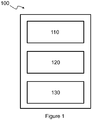
- FIG. 1 illustrates a tracking system 100 according to some examples.
- Head tracking system 100 is for use with a head mounted display to track the head and/or the eyes of a user of the head mounted display on a watercraft.
- the tracking system 100 comprises optical tracking circuitry 110, non-optical tracking circuitry 120 and correction circuitry 130.
- the optical tracking circuitry 110 determines first tracking information of the head mounted display using optical tracking means.
- the optical tracking means may comprise at least one optical source, such as a laser or light emitting diode, and at least one optical detector.
- the at least one optical source may be located on the head mounted display, or alternatively the optical detectors may be located on the head mounted display.
- Non-optical tracking circuity comprises non-optical means to provide second tracking information.
- the non-optical tracking means may comprise at least one inertial sensor.
- the head mounted display may comprise at least one inertial sensor attached to or associated with the head mounted display, and also the watercraft may also comprise at least one inertial sensor attached to or associated with the watercraft.
- Correction circuitry 130 uses the first and second tracking information to provide updated tracking information.
- the tracking system 1000 may further comprise a prediction circuitry.
- the prediction circuitry may incorporate additional data from sources such as sensors, accelerometers and gyroscopes to improve the perceived latency and conformal accuracy of the head mounted display and use such data to predict the position of gaze, a number of frames ahead of real-time.
- the sensors, accelerometers and gyroscopes may be associated and/or mounted to the head mounted display.
- the sensors, accelerometers and gyroscopes may be associated and/or mounted to the watercraft.
- the prediction circuitry may preferably predict the position and gaze no more than 100 ms in advance.
- the prediction circuitry may use a combination of information received from data sources associated with the watercraft and data sources associated with head mounted display.
- the data sources associated with the watercraft may comprise sensors, accelerometers and gyroscopes mounted to the watercraft.
- the data sources associated with the head mounted display may comprise sensors, accelerometers and gyroscopes mounted to the head mounted display. This combination may improve the perceived latency and accuracy of symbol conformity to objects.
- the watercraft may have a predictable motion due to roll caused by the motion of the sea and this information combined with information regarding the movement of the head of the user of the head mounted display further reducing the perceived latency.
- the optical and/or non-optical tracking means are selected by the tracking system 100 based on the location of the head mounted display. This may allow the tracking system 100 to track the head mounted display over a large area.
- the tracking system 100 selects a non-optical tracking means based on the location of the head mounted display. This is further illustrated by Figure 2 .
- FIG. 2 illustrates a tracked watercraft 200 according to some examples.
- the tracked watercraft 200 comprises a first axis 210 and a second axis 250 about which the tracked watercraft 200 may be deformed, for example a flex, rotation, or a compression.
- the tracked watercraft 200 may comprise other axes not shown in Figure 2 that it is also deformed about.
- Tracked watercraft 200 also comprises a first tracking location 220, second tracking location 230, and third tracking location 240.
- the tracked watercraft may also comprise a reference area 260.
- the first tracking location 220, second tracking location 230, and third tracking location 240 are each areas of the tracked watercraft that the user may be tracked.
- Non-optical tracking means may be provided at least at the reference area 260.
- Reference area 260 may be chosen as a positon or area on the tracked watercraft 200 that is known to have the least deformation. In some examples, knowing conditions regarding the tracked watercraft may allow for calculation to be made regarding the relative movement of the first tracking location 220, second tracking location 230, and third tracking location 240, and therefore a correction may be made to the second tracking information based on the location of the user.
- At least one of the first tracking location 220, second tracking location 230, and third tracking location 240 may comprise non-optical tracking means, this may be in addition to the non-optical tracking means in the reference area 260.
- the selection of the non-optical tracking means may be based on the location of the head mounted display, such that the tracker system 100 uses non-optical tracking means associated with the first tracking location 220 when nearest the first tracking location, uses non-optical tracking means associated with the second tracking location 230 when nearest the second tracking location, and uses non-optical tracking means associated with the third tracking location 230 when nearest the third tracking location.
- the selection of the appropriate non-optical tracking means may not be based purely on distance.
- the tracked watercraft 200 may be known to have more flex at a certain location, and therefore the distance may be a weighted distance based on the predicted deformation of the tracked watercraft.
- the tracker system may also take into account the motion of at least two of the first tracking location 220, second tracking location 230, third tracking location 240, and reference area 260 to such that for a known positon on the watercraft 200 a movement relative to the reference movement can be determined based on known properties of the tracked watercraft 200.
- the number of tracking areas is illustrative, and the tracked watercraft 200 may comprise any number of tracked areas.
- the tracked areas may be discrete, such that they have defined boundaries.
- the tracked areas may be continuous, such that there is not a well-defined boundary.
- none or at least one of the tracked areas may overlap.
- at least one of the tracking locations may comprise a bridge of the watercraft.
- the non-optical tracking means may comprise at least one inertial sensor.
- the non-optical tracking means may comprise a set of inertial sensors to measure movement of the helmet relative to the watercraft, and a plurality of sets of inertial sensors to measure the movement of the watercraft relative to the surroundings.
- the tracking system may select one of the plurality of sets of inertial sensors based on the location of the head mounted display.
- the plurality of sets of inertial sensors may be disjoint sets, such that each set does not share any sensor with any other set of inertial sensors.
- the optical tracking means may comprise a size-variable optical tracking mark.
- the size of the size-variable optical tracking mark may be configured to change based on the location of the head mounted display.
- the size may be based on the distance from the size-variable optical tracking mark, or from a defined position in the watercraft or tracking area.
- the distance may also be a weighted distance.
- Figure 3 illustrates the size-variable optical tracking mark in use.
- a head mounted display 300 is located at a first distance 310a from the size-variable optical tracking mark 320. This results in the size-variable optical tracking mark 320 having a first size 330a.
- the size-variable optical tracking mark 320 has a second size 330b.
- the size-variable optical tracking mark may vary size mechanically, such as by expanding, contracting or a rotation.
- the optical tracking marks may comprise an active device, such as a light source, or a passive device such as a reflector or a detector.
- Figure 4 illustrates a cross-shaped size-variable optical tracking mark 400 according to some examples.
- the shape is illustrative, and it is understood that the size-variable optical tracking mark may have any shape.
- the size-variable optical tracking mark may be configured to increase size in all angles, rather than vertically and horizontally.
- a single optical tracking mark 410a may be used by the tracker system and six optical tracking marks not used 420a. If the head mounted display is located at a second distance from the cross-shaped size-variable optical tracking mark 400 then a further four optical tracking marks may be used 410b, and four optical tracking marks not used 420b, wherein the first distance is less than the second distance. If the head mounted display is located at a third distance from the cross-shaped size-variable optical tracking mark 400 then a further four optical tracking marks may be used 410c, and no optical tracking marks not used, wherein the third distance is more than the second and first distances.
- the tracking system may also comprise a plurality of size-variable optical tracking marks and a plurality of constant-size optical tracking marks which do not change size.
- the walls of the tracked area may comprise size-variable optical tracking marks as the user may move towards and away from the walls, but the ceiling may comprise constant-size optical tracking marks as the user may not significantly change the distance from the ceiling to the head mounted display, at least in the vertical direction.
- the size-variable optical tracking marks are illustrated as increasing size from the centre, however they are not limited to increasing in this manner.
- the number of size-variable marks is not required to increase with distance of the user form the marks. In some examples the number of size-variable tracking marks may stay constant, such that the spacing of the marks increase with increasing distance of the user from the marks.
- the intensity of the marks may depend on the distance of the user from the mark. In some examples the intensity of the mark may be relatively constant with distance.
- Figure 5 illustrates a method 500 according to some examples.
- the method comprises determining first tracking information 510, determining second tracking information 520, and determining updated tracking information 530.
- Determining first tracking information 510 comprises using optical tracking means to determine the first tracking information using optical tracking means.
- the optical tracking means may comprise at least one optical sensor and at least one optical source.
- the optical detectors may be located on the head mounted display, or the optical sources may be located on the head mounted display.
- Determining second tracking information 520 comprises using non-optical tracking means to determine the second tracking information using non-optical tracking means.
- the selection of at least one of the optical tracking means and non-optical tracking means may be based on the location of the head mounted display.
- the method may comprise selecting a non-optical tracking means based on the location of the head mounted display.
- a watercraft may comprise a plurality of tracked areas, and the selecting the non-optical tracking means may comprise selecting a subset of the non-optical tracking means, the subset of the non-optical tracking means being closest to the head mounted display.
- the method may comprise providing the location of the head mounted display to the optical means, and basing the size of the variable-sized marks on the distance from the variable-sized mark to the head mounted display.
- the location of the head mounted display may be a rough estimation.
- the tracking system may determine the location by performing a measurement.
- the location may be a relative location, such that the location provides information regarding the distance from the size-variable optical tracking mark but does not provide the absolute location of the head mounted display on the watercraft.
- tracking system 100 may be used with any type of application where a user's head is required to be tracked over a large volume.
Landscapes
- Engineering & Computer Science (AREA)
- Physics & Mathematics (AREA)
- General Physics & Mathematics (AREA)
- General Engineering & Computer Science (AREA)
- Theoretical Computer Science (AREA)
- Optics & Photonics (AREA)
- Human Computer Interaction (AREA)
- Chemical & Material Sciences (AREA)
- Mechanical Engineering (AREA)
- Ocean & Marine Engineering (AREA)
- Combustion & Propulsion (AREA)
- Remote Sensing (AREA)
- Radar, Positioning & Navigation (AREA)
- Length Measuring Devices By Optical Means (AREA)
- Controls And Circuits For Display Device (AREA)
Abstract
A tracking system for use with a head mounted display on a watercraft is disclosed. The tracking system comprises: optical tracking circuitry to determine first tracking information of the head mounted display using optical tracking means; non-optical circuitry to determine second tracking information of the head mounted display using non-optical tracking means; and correction circuitry to determine an updated tracking information of the head mounted display based on the first tracking information and the second tracking information. The selection of at least the optical tracking means or non-optical tracking means to use to determine the first tracking information and the second tracking information is based on a location of the head mounted display.
Description
- Head mounted displays are a type of display that allow a user to view a scene whilst viewing information over the scene, and at the same time having freedom of movement to move their head position. Head mounted displays may comprise a tracking system. However, tracking systems are typically designed to function in a closed environment, such as an aircraft cockpit, where the freedom of movement of the user is constrained to a relatively small volume. Therefore the tracking systems are not typically capable to track movement accurately over large volumes or large movements.
-
-
Figure 1 illustrates a tracking system in accordance with some examples. -
Figure 2 illustrates a watercraft in accordance with some examples. -
Figure 3 illustrates a size-variable optical mark in use. -
Figure 4 further illustrates a size-variable optical mark in use. -
Figure 5 illustrates a method for use with a tracking system in accordance with some examples. - It may be desirable for user on a watercraft to be provided with information regarding their surroundings and watercraft visually. This may be provided with a head mounted display. The information should be overlaid with objects in the field of view of the user, and therefore a tracker system is desirable for the head mounted display. However, it is also may be desirable for the user to be able to move freely about the watercraft, and to be able to view the information at a wide range of viewing angles and positons. Therefore, the tracking system should allow the user to be able to move substantially freely over a large volume whilst still being provided with information aligned with objects in their field of view.
-
Figure 1 illustrates atracking system 100 according to some examples.Head tracking system 100 is for use with a head mounted display to track the head and/or the eyes of a user of the head mounted display on a watercraft. Thetracking system 100 comprisesoptical tracking circuitry 110,non-optical tracking circuitry 120 andcorrection circuitry 130. - The
optical tracking circuitry 110 determines first tracking information of the head mounted display using optical tracking means. The optical tracking means may comprise at least one optical source, such as a laser or light emitting diode, and at least one optical detector. The at least one optical source may be located on the head mounted display, or alternatively the optical detectors may be located on the head mounted display. - Non-optical tracking circuity comprises non-optical means to provide second tracking information. The non-optical tracking means may comprise at least one inertial sensor. The head mounted display may comprise at least one inertial sensor attached to or associated with the head mounted display, and also the watercraft may also comprise at least one inertial sensor attached to or associated with the watercraft.
-
Correction circuitry 130 uses the first and second tracking information to provide updated tracking information. - In some examples the tracking system 1000 may further comprise a prediction circuitry. The prediction circuitry may incorporate additional data from sources such as sensors, accelerometers and gyroscopes to improve the perceived latency and conformal accuracy of the head mounted display and use such data to predict the position of gaze, a number of frames ahead of real-time. In some examples the sensors, accelerometers and gyroscopes may be associated and/or mounted to the head mounted display. In some examples the sensors, accelerometers and gyroscopes may be associated and/or mounted to the watercraft. The prediction circuitry may preferably predict the position and gaze no more than 100 ms in advance.
- In some examples the prediction circuitry may use a combination of information received from data sources associated with the watercraft and data sources associated with head mounted display. The data sources associated with the watercraft may comprise sensors, accelerometers and gyroscopes mounted to the watercraft. The data sources associated with the head mounted display may comprise sensors, accelerometers and gyroscopes mounted to the head mounted display. This combination may improve the perceived latency and accuracy of symbol conformity to objects.
- For example, the watercraft may have a predictable motion due to roll caused by the motion of the sea and this information combined with information regarding the movement of the head of the user of the head mounted display further reducing the perceived latency.
- The optical and/or non-optical tracking means are selected by the
tracking system 100 based on the location of the head mounted display. This may allow thetracking system 100 to track the head mounted display over a large area. - In some examples the
tracking system 100 selects a non-optical tracking means based on the location of the head mounted display. This is further illustrated byFigure 2 . -
Figure 2 illustrates a trackedwatercraft 200 according to some examples. The trackedwatercraft 200 comprises afirst axis 210 and asecond axis 250 about which the trackedwatercraft 200 may be deformed, for example a flex, rotation, or a compression. The trackedwatercraft 200 may comprise other axes not shown inFigure 2 that it is also deformed about. Trackedwatercraft 200 also comprises afirst tracking location 220,second tracking location 230, andthird tracking location 240. The tracked watercraft may also comprise areference area 260. Thefirst tracking location 220,second tracking location 230, andthird tracking location 240 are each areas of the tracked watercraft that the user may be tracked. - Non-optical tracking means may be provided at least at the
reference area 260.Reference area 260 may be chosen as a positon or area on the trackedwatercraft 200 that is known to have the least deformation. In some examples, knowing conditions regarding the tracked watercraft may allow for calculation to be made regarding the relative movement of thefirst tracking location 220,second tracking location 230, andthird tracking location 240, and therefore a correction may be made to the second tracking information based on the location of the user. - In some examples, at least one of the
first tracking location 220,second tracking location 230, andthird tracking location 240 may comprise non-optical tracking means, this may be in addition to the non-optical tracking means in thereference area 260. The selection of the non-optical tracking means may be based on the location of the head mounted display, such that thetracker system 100 uses non-optical tracking means associated with thefirst tracking location 220 when nearest the first tracking location, uses non-optical tracking means associated with thesecond tracking location 230 when nearest the second tracking location, and uses non-optical tracking means associated with thethird tracking location 230 when nearest the third tracking location. - The selection of the appropriate non-optical tracking means may not be based purely on distance. For example, the tracked
watercraft 200 may be known to have more flex at a certain location, and therefore the distance may be a weighted distance based on the predicted deformation of the tracked watercraft. - The tracker system may also take into account the motion of at least two of the
first tracking location 220,second tracking location 230,third tracking location 240, andreference area 260 to such that for a known positon on the watercraft 200 a movement relative to the reference movement can be determined based on known properties of the trackedwatercraft 200. - The number of tracking areas is illustrative, and the tracked
watercraft 200 may comprise any number of tracked areas. In some examples the tracked areas may be discrete, such that they have defined boundaries. In some examples the tracked areas may be continuous, such that there is not a well-defined boundary. In some examples none or at least one of the tracked areas may overlap. In some examples at least one of the tracking locations may comprise a bridge of the watercraft. - In some examples the non-optical tracking means may comprise at least one inertial sensor. The non-optical tracking means may comprise a set of inertial sensors to measure movement of the helmet relative to the watercraft, and a plurality of sets of inertial sensors to measure the movement of the watercraft relative to the surroundings. The tracking system may select one of the plurality of sets of inertial sensors based on the location of the head mounted display. The plurality of sets of inertial sensors may be disjoint sets, such that each set does not share any sensor with any other set of inertial sensors.
- In some examples, the optical tracking means may comprise a size-variable optical tracking mark. The size of the size-variable optical tracking mark may be configured to change based on the location of the head mounted display. The size may be based on the distance from the size-variable optical tracking mark, or from a defined position in the watercraft or tracking area. The distance may also be a weighted distance.
-
Figure 3 illustrates the size-variable optical tracking mark in use. A head mounteddisplay 300 is located at afirst distance 310a from the size-variableoptical tracking mark 320. This results in the size-variableoptical tracking mark 320 having afirst size 330a. When the head mounteddisplay 300 is located at asecond distance 310b from the size-variableoptical tracking mark 320 the size-variableoptical tracking mark 320 has asecond size 330b. - The size-variable optical tracking mark may vary size mechanically, such as by expanding, contracting or a rotation.
- The optical tracking marks may comprise an active device, such as a light source, or a passive device such as a reflector or a detector.
-
Figure 4 illustrates a cross-shaped size-variableoptical tracking mark 400 according to some examples. The shape is illustrative, and it is understood that the size-variable optical tracking mark may have any shape. Furthermore, the size-variable optical tracking mark may be configured to increase size in all angles, rather than vertically and horizontally. - If the head mounted display is located at a first distance from the cross-shaped size-variable
optical tracking mark 400, then a singleoptical tracking mark 410a may be used by the tracker system and six optical tracking marks not used 420a. If the head mounted display is located at a second distance from the cross-shaped size-variableoptical tracking mark 400 then a further four optical tracking marks may be used 410b, and four optical tracking marks not used 420b, wherein the first distance is less than the second distance. If the head mounted display is located at a third distance from the cross-shaped size-variableoptical tracking mark 400 then a further four optical tracking marks may be used 410c, and no optical tracking marks not used, wherein the third distance is more than the second and first distances. - The tracking system may also comprise a plurality of size-variable optical tracking marks and a plurality of constant-size optical tracking marks which do not change size. For example, the walls of the tracked area may comprise size-variable optical tracking marks as the user may move towards and away from the walls, but the ceiling may comprise constant-size optical tracking marks as the user may not significantly change the distance from the ceiling to the head mounted display, at least in the vertical direction.
- The size-variable optical tracking marks are illustrated as increasing size from the centre, however they are not limited to increasing in this manner. The number of size-variable marks is not required to increase with distance of the user form the marks. In some examples the number of size-variable tracking marks may stay constant, such that the spacing of the marks increase with increasing distance of the user from the marks.
- In some examples the intensity of the marks may depend on the distance of the user from the mark. In some examples the intensity of the mark may be relatively constant with distance.
-
Figure 5 illustrates amethod 500 according to some examples. The method comprises determiningfirst tracking information 510, determiningsecond tracking information 520, and determining updatedtracking information 530. - Determining first tracking
information 510 comprises using optical tracking means to determine the first tracking information using optical tracking means. The optical tracking means may comprise at least one optical sensor and at least one optical source. The optical detectors may be located on the head mounted display, or the optical sources may be located on the head mounted display. - Determining
second tracking information 520 comprises using non-optical tracking means to determine the second tracking information using non-optical tracking means. - The selection of at least one of the optical tracking means and non-optical tracking means may be based on the location of the head mounted display.
- In some examples the method may comprise selecting a non-optical tracking means based on the location of the head mounted display. A watercraft may comprise a plurality of tracked areas, and the selecting the non-optical tracking means may comprise selecting a subset of the non-optical tracking means, the subset of the non-optical tracking means being closest to the head mounted display.
- In some examples the method may comprise providing the location of the head mounted display to the optical means, and basing the size of the variable-sized marks on the distance from the variable-sized mark to the head mounted display. The location of the head mounted display may be a rough estimation. In some examples the tracking system may determine the location by performing a measurement. In some examples the location may be a relative location, such that the location provides information regarding the distance from the size-variable optical tracking mark but does not provide the absolute location of the head mounted display on the watercraft.
- Although the above examples are described in relation to watercraft, it should be understood that tracking
system 100 may be used with any type of application where a user's head is required to be tracked over a large volume.
Claims (15)
1. A tracking system for use with a head mounted display on a watercraft, the tracking system comprising:
optical tracking circuitry to determine first tracking information of the head mounted display using optical tracking means;
non-optical circuitry to determine second tracking information of the head mounted display using non-optical tracking means;
correction circuitry to determine an updated tracking information of the head mounted display based on the first tracking information and the second tracking information; and wherein
selection of at least the optical tracking means or non-optical tracking means to use to determine the first tracking information and the second tracking information is based on a location of the head mounted display. 2. The tracking system according to claim 1, wherein the non-optical tracking means comprises a plurality of disjoint sets of inertial sensors located on the watercraft, each individual set comprising at least one inertial sensor, each set located in separate locations of the watercraft, wherein the selection of which of the plurality of sets of inertial sensors to use to determine the second tracking information is based on the location of the head mounted display.
3. The tracking system according to any preceding claim, wherein the optical tracking means comprises at least one size-variable optical tracking mark, a size and configuration of the variable-sized alignment mark is based on the location of the head mounted display.
4. The tracking system according to claim 3, wherein the size-variable optical tracking mark comprises at least one light source.
5. The tracking system according to claim 4, wherein the at least one light source comprises a light emitting diode.
6. The tracking system according to any preceding claim, wherein the non-optical circuity is configured to calculate the second tracking information based on an estimate of the physical deformation at the location of the head mounted display.
7. The tracking system according to claim 6, wherein the estimate of the physical deformation is based upon non-optical tracking means at at least two separate locations.
8. The tracking system according to any preceding claim, wherein the tracking system further comprises prediction circuitry.
9. A watercraft comprising the tracking system of any of claims 1-8.
10. A method for use with a tracking system according to any of claims 1-8, the method comprising:
determining first tracking information of a head mounted display based on optical tracking means;
determining second tracking information of a head mounted display based on non-optical tracking means;
determining an updated tracking information of the head mounted display based on the first tracking information and the second tracking information; and wherein
selecting at least the optical tracking means or non-optical tracking means to use to determine the first tracking information and the second tracking information is based on a location of the head mounted display.
11. The method according to claim 10, wherein the non-optical tracking means comprises a plurality of sets of inertial sensors located on the watercraft, each individual set comprising at least one inertial sensor, each set located in separate locations of the watercraft, and selecting the optical tracking means comprises selecting one of the sets of inertial sensors based on the location of the head mounted display.
12. The method according to claim 10 or 11, wherein the optical tracking means comprises at least one variable-sized mark, a size and configuration of the variable-sized alignment mark is based on the location of the head mounted display.
13. The method according to any of claims 10-12, wherein determining the second tracking information is based on an estimate of the physical deformation at the location of the head mounted display.
13. The method according to claim 13, wherein the estimate of the physical deformation is based upon non-optical tracking means at at least two separate locations
15. A machine readable medium comprising instructions, that when executed, cause a processing means to perform the method of any of claims 10-14.
Priority Applications (6)
| Application Number | Priority Date | Filing Date | Title |
|---|---|---|---|
| GB1917648.6A GB2581238B (en) | 2018-12-06 | 2019-12-03 | Tracking system |
| EP19816859.3A EP3891582B1 (en) | 2018-12-06 | 2019-12-03 | Tracking system for use with a head-mounted display on a watercraft |
| CA3119908A CA3119908A1 (en) | 2018-12-06 | 2019-12-03 | Tracking system |
| AU2019393148A AU2019393148B2 (en) | 2018-12-06 | 2019-12-03 | Tracking system |
| US17/296,633 US11796800B2 (en) | 2018-12-06 | 2019-12-03 | Tracking system |
| PCT/GB2019/053411 WO2020115466A1 (en) | 2018-12-06 | 2019-12-03 | Tracking system |
Applications Claiming Priority (1)
| Application Number | Priority Date | Filing Date | Title |
|---|---|---|---|
| GBGB1819896.0A GB201819896D0 (en) | 2018-12-06 | 2018-12-06 | Tracking system |
Publications (1)
| Publication Number | Publication Date |
|---|---|
| EP3663895A1 true EP3663895A1 (en) | 2020-06-10 |
Family
ID=65029963
Family Applications (2)
| Application Number | Title | Priority Date | Filing Date |
|---|---|---|---|
| EP19150823.3A Ceased EP3663895A1 (en) | 2018-12-06 | 2019-01-08 | Tracking system for use with a head mounted display on a watercraft |
| EP19816859.3A Active EP3891582B1 (en) | 2018-12-06 | 2019-12-03 | Tracking system for use with a head-mounted display on a watercraft |
Family Applications After (1)
| Application Number | Title | Priority Date | Filing Date |
|---|---|---|---|
| EP19816859.3A Active EP3891582B1 (en) | 2018-12-06 | 2019-12-03 | Tracking system for use with a head-mounted display on a watercraft |
Country Status (6)
| Country | Link |
|---|---|
| US (1) | US11796800B2 (en) |
| EP (2) | EP3663895A1 (en) |
| AU (1) | AU2019393148B2 (en) |
| CA (1) | CA3119908A1 (en) |
| GB (2) | GB201819896D0 (en) |
| WO (1) | WO2020115466A1 (en) |
Families Citing this family (2)
| Publication number | Priority date | Publication date | Assignee | Title |
|---|---|---|---|---|
| GB201819895D0 (en) | 2018-12-06 | 2019-01-23 | Bae Systems Plc | Head mounted display system |
| GB201819896D0 (en) | 2018-12-06 | 2019-01-23 | Bae Systems Plc | Tracking system |
Citations (2)
| Publication number | Priority date | Publication date | Assignee | Title |
|---|---|---|---|---|
| US20130278635A1 (en) * | 2011-08-25 | 2013-10-24 | Sartorius Stedim Biotech Gmbh | Assembling method, monitoring method, communication method, augmented reality system and computer program product |
| WO2017042588A1 (en) * | 2015-09-11 | 2017-03-16 | Bae Systems Plc | Helmet tracker buffeting compensation |
Family Cites Families (20)
| Publication number | Priority date | Publication date | Assignee | Title |
|---|---|---|---|---|
| US20030210228A1 (en) | 2000-02-25 | 2003-11-13 | Ebersole John Franklin | Augmented reality situational awareness system and method |
| US7128705B2 (en) | 2002-11-26 | 2006-10-31 | Artis Llc | Motion-coupled visual environment for prevention or reduction of motion sickness and simulator/virtual environment sickness |
| US10585472B2 (en) * | 2011-08-12 | 2020-03-10 | Sony Interactive Entertainment Inc. | Wireless head mounted display with differential rendering and sound localization |
| KR20160005695A (en) * | 2013-04-30 | 2016-01-15 | 인텔렉추얼디스커버리 주식회사 | A Head Mounted Display and A Method for Providing Audio Contents Using the Same |
| US10269132B2 (en) * | 2014-07-31 | 2019-04-23 | Sony Corporation | Displaying images according to head posture and camera posture |
| US10444018B2 (en) * | 2015-02-27 | 2019-10-15 | Microsoft Technology Licensing, Llc | Computer-implemented method to test the sensitivity of a sensor for detecting movement of a tracking device within an established frame of reference of a moving platform |
| GB2561746B (en) | 2015-11-13 | 2022-02-09 | Flir Systems | Video sensor fusion and model based virtual and augmented reality systems and methods |
| US9891705B1 (en) * | 2016-08-25 | 2018-02-13 | Rockwell Collins, Inc. | Automatic boresighting of head-worn display |
| GB2556910A (en) | 2016-11-25 | 2018-06-13 | Nokia Technologies Oy | Virtual reality display |
| GB2559809B (en) | 2017-02-21 | 2020-07-08 | Sony Interactive Entertainment Europe Ltd | Motion tracking apparatus and system |
| GB2561852A (en) | 2017-04-25 | 2018-10-31 | Bae Systems Plc | Watercraft |
| EP3395668A1 (en) | 2017-04-25 | 2018-10-31 | BAE SYSTEMS plc | Watercraft |
| WO2018227098A1 (en) | 2017-06-09 | 2018-12-13 | Vid Scale, Inc. | External camera assisted virtual reality |
| WO2018232093A1 (en) * | 2017-06-14 | 2018-12-20 | Sony Interactive Entertainment Inc. | Tracking using retroreflectors mounted on a head-mounted display |
| US10733799B2 (en) | 2017-07-26 | 2020-08-04 | Daqri, Llc | Augmented reality sensor |
| US10223805B1 (en) * | 2017-08-07 | 2019-03-05 | Facebook Technologies, Llc | Coded tracking for head-mounted displays |
| EP3714318B1 (en) * | 2018-01-18 | 2023-08-30 | Valve Corporation | Position tracking system for head-mounted displays that includes sensor integrated circuits |
| WO2020024909A1 (en) * | 2018-08-02 | 2020-02-06 | 广东虚拟现实科技有限公司 | Positioning and tracking method, terminal device, and computer readable storage medium |
| GB201819896D0 (en) | 2018-12-06 | 2019-01-23 | Bae Systems Plc | Tracking system |
| GB201819895D0 (en) | 2018-12-06 | 2019-01-23 | Bae Systems Plc | Head mounted display system |
-
2018
- 2018-12-06 GB GBGB1819896.0A patent/GB201819896D0/en not_active Ceased
-
2019
- 2019-01-08 EP EP19150823.3A patent/EP3663895A1/en not_active Ceased
- 2019-12-03 CA CA3119908A patent/CA3119908A1/en active Pending
- 2019-12-03 EP EP19816859.3A patent/EP3891582B1/en active Active
- 2019-12-03 US US17/296,633 patent/US11796800B2/en active Active
- 2019-12-03 AU AU2019393148A patent/AU2019393148B2/en active Active
- 2019-12-03 GB GB1917648.6A patent/GB2581238B/en active Active
- 2019-12-03 WO PCT/GB2019/053411 patent/WO2020115466A1/en not_active Ceased
Patent Citations (2)
| Publication number | Priority date | Publication date | Assignee | Title |
|---|---|---|---|---|
| US20130278635A1 (en) * | 2011-08-25 | 2013-10-24 | Sartorius Stedim Biotech Gmbh | Assembling method, monitoring method, communication method, augmented reality system and computer program product |
| WO2017042588A1 (en) * | 2015-09-11 | 2017-03-16 | Bae Systems Plc | Helmet tracker buffeting compensation |
Also Published As
| Publication number | Publication date |
|---|---|
| GB201917648D0 (en) | 2020-01-15 |
| AU2019393148A1 (en) | 2021-06-10 |
| WO2020115466A1 (en) | 2020-06-11 |
| EP3891582B1 (en) | 2025-09-17 |
| US20220026710A1 (en) | 2022-01-27 |
| GB2581238A (en) | 2020-08-12 |
| AU2019393148B2 (en) | 2025-05-29 |
| GB201819896D0 (en) | 2019-01-23 |
| EP3891582A1 (en) | 2021-10-13 |
| CA3119908A1 (en) | 2020-06-11 |
| US11796800B2 (en) | 2023-10-24 |
| GB2581238B (en) | 2021-05-19 |
Similar Documents
| Publication | Publication Date | Title |
|---|---|---|
| KR101762297B1 (en) | Calibration of virtual reality systems | |
| JP7319303B2 (en) | Radar head pose localization | |
| US11024040B2 (en) | Dynamic object tracking | |
| US11694345B2 (en) | Moving object tracking using object and scene trackers | |
| EP3891582B1 (en) | Tracking system for use with a head-mounted display on a watercraft | |
| JP7191104B2 (en) | Method, positioning system, tracker and computer program for determining the current position of an object | |
| JP5292725B2 (en) | Motion tracker device | |
| US12264919B2 (en) | Head mounted display system | |
| KR20160038476A (en) | Apparatus and Method for calibrating Gaze | |
| EP3975040A1 (en) | Large space tracking using a wearable optics device | |
| GB2599145A (en) | Large space tracking using a wearable optics device | |
| KR101672710B1 (en) | Indoor monitoring system using augmented reality | |
| JP4656016B2 (en) | Motion tracker device | |
| EP4661388A1 (en) | Marker projection device | |
| US20230367390A1 (en) | Large space tracking using a wearable optics device |
Legal Events
| Date | Code | Title | Description |
|---|---|---|---|
| PUAI | Public reference made under article 153(3) epc to a published international application that has entered the european phase |
Free format text: ORIGINAL CODE: 0009012 |
|
| AK | Designated contracting states |
Kind code of ref document: A1 Designated state(s): AL AT BE BG CH CY CZ DE DK EE ES FI FR GB GR HR HU IE IS IT LI LT LU LV MC MK MT NL NO PL PT RO RS SE SI SK SM TR |
|
| AX | Request for extension of the european patent |
Extension state: BA ME |
|
| STAA | Information on the status of an ep patent application or granted ep patent |
Free format text: STATUS: THE APPLICATION HAS BEEN REFUSED |
|
| 18R | Application refused |
Effective date: 20200626 |