EP3663814A1 - Cover device for near-infrared sensors - Google Patents
Cover device for near-infrared sensors Download PDFInfo
- Publication number
- EP3663814A1 EP3663814A1 EP18858249.8A EP18858249A EP3663814A1 EP 3663814 A1 EP3663814 A1 EP 3663814A1 EP 18858249 A EP18858249 A EP 18858249A EP 3663814 A1 EP3663814 A1 EP 3663814A1
- Authority
- EP
- European Patent Office
- Prior art keywords
- cover
- infrared sensor
- decorative layer
- infrared
- visible light
- Prior art date
- Legal status (The legal status is an assumption and is not a legal conclusion. Google has not performed a legal analysis and makes no representation as to the accuracy of the status listed.)
- Granted
Links
Images




Classifications
-
- G—PHYSICS
- G01—MEASURING; TESTING
- G01N—INVESTIGATING OR ANALYSING MATERIALS BY DETERMINING THEIR CHEMICAL OR PHYSICAL PROPERTIES
- G01N21/00—Investigating or analysing materials by the use of optical means, i.e. using sub-millimetre waves, infrared, visible or ultraviolet light
- G01N21/17—Systems in which incident light is modified in accordance with the properties of the material investigated
- G01N21/25—Colour; Spectral properties, i.e. comparison of effect of material on the light at two or more different wavelengths or wavelength bands
- G01N21/31—Investigating relative effect of material at wavelengths characteristic of specific elements or molecules, e.g. atomic absorption spectrometry
- G01N21/35—Investigating relative effect of material at wavelengths characteristic of specific elements or molecules, e.g. atomic absorption spectrometry using infrared light
- G01N21/359—Investigating relative effect of material at wavelengths characteristic of specific elements or molecules, e.g. atomic absorption spectrometry using infrared light using near infrared light
-
- G—PHYSICS
- G02—OPTICS
- G02B—OPTICAL ELEMENTS, SYSTEMS OR APPARATUS
- G02B5/00—Optical elements other than lenses
- G02B5/20—Filters
- G02B5/208—Filters for use with infrared or ultraviolet radiation, e.g. for separating visible light from infrared and/or ultraviolet radiation
-
- B—PERFORMING OPERATIONS; TRANSPORTING
- B60—VEHICLES IN GENERAL
- B60Q—ARRANGEMENT OF SIGNALLING OR LIGHTING DEVICES, THE MOUNTING OR SUPPORTING THEREOF OR CIRCUITS THEREFOR, FOR VEHICLES IN GENERAL
- B60Q1/00—Arrangement of optical signalling or lighting devices, the mounting or supporting thereof or circuits therefor
- B60Q1/0017—Devices integrating an element dedicated to another function
- B60Q1/0023—Devices integrating an element dedicated to another function the element being a sensor, e.g. distance sensor, camera
-
- B—PERFORMING OPERATIONS; TRANSPORTING
- B60—VEHICLES IN GENERAL
- B60R—VEHICLES, VEHICLE FITTINGS, OR VEHICLE PARTS, NOT OTHERWISE PROVIDED FOR
- B60R13/00—Elements for body-finishing, identifying, or decorating; Arrangements or adaptations for advertising purposes
- B60R13/04—External Ornamental or guard strips; Ornamental inscriptive devices thereon
-
- F—MECHANICAL ENGINEERING; LIGHTING; HEATING; WEAPONS; BLASTING
- F21—LIGHTING
- F21S—NON-PORTABLE LIGHTING DEVICES; SYSTEMS THEREOF; VEHICLE LIGHTING DEVICES SPECIALLY ADAPTED FOR VEHICLE EXTERIORS
- F21S43/00—Signalling devices specially adapted for vehicle exteriors, e.g. brake lamps, direction indicator lights or reversing lights
- F21S43/20—Signalling devices specially adapted for vehicle exteriors, e.g. brake lamps, direction indicator lights or reversing lights characterised by refractors, transparent cover plates, light guides or filters
-
- F—MECHANICAL ENGINEERING; LIGHTING; HEATING; WEAPONS; BLASTING
- F21—LIGHTING
- F21S—NON-PORTABLE LIGHTING DEVICES; SYSTEMS THEREOF; VEHICLE LIGHTING DEVICES SPECIALLY ADAPTED FOR VEHICLE EXTERIORS
- F21S43/00—Signalling devices specially adapted for vehicle exteriors, e.g. brake lamps, direction indicator lights or reversing lights
- F21S43/20—Signalling devices specially adapted for vehicle exteriors, e.g. brake lamps, direction indicator lights or reversing lights characterised by refractors, transparent cover plates, light guides or filters
- F21S43/281—Materials thereof; Structures thereof; Properties thereof; Coatings thereof
-
- G—PHYSICS
- G01—MEASURING; TESTING
- G01S—RADIO DIRECTION-FINDING; RADIO NAVIGATION; DETERMINING DISTANCE OR VELOCITY BY USE OF RADIO WAVES; LOCATING OR PRESENCE-DETECTING BY USE OF THE REFLECTION OR RERADIATION OF RADIO WAVES; ANALOGOUS ARRANGEMENTS USING OTHER WAVES
- G01S7/00—Details of systems according to groups G01S13/00, G01S15/00, G01S17/00
- G01S7/48—Details of systems according to groups G01S13/00, G01S15/00, G01S17/00 of systems according to group G01S17/00
- G01S7/481—Constructional features, e.g. arrangements of optical elements
-
- G—PHYSICS
- G02—OPTICS
- G02B—OPTICAL ELEMENTS, SYSTEMS OR APPARATUS
- G02B5/00—Optical elements other than lenses
- G02B5/20—Filters
- G02B5/26—Reflecting filters
-
- G—PHYSICS
- G02—OPTICS
- G02B—OPTICAL ELEMENTS, SYSTEMS OR APPARATUS
- G02B5/00—Optical elements other than lenses
- G02B5/20—Filters
- G02B5/28—Interference filters
- G02B5/281—Interference filters designed for the infrared light
-
- B—PERFORMING OPERATIONS; TRANSPORTING
- B60—VEHICLES IN GENERAL
- B60Q—ARRANGEMENT OF SIGNALLING OR LIGHTING DEVICES, THE MOUNTING OR SUPPORTING THEREOF OR CIRCUITS THEREFOR, FOR VEHICLES IN GENERAL
- B60Q1/00—Arrangement of optical signalling or lighting devices, the mounting or supporting thereof or circuits therefor
- B60Q1/26—Arrangement of optical signalling or lighting devices, the mounting or supporting thereof or circuits therefor the devices being primarily intended to indicate the vehicle, or parts thereof, or to give signals, to other traffic
- B60Q1/50—Arrangement of optical signalling or lighting devices, the mounting or supporting thereof or circuits therefor the devices being primarily intended to indicate the vehicle, or parts thereof, or to give signals, to other traffic for indicating other intentions or conditions, e.g. request for waiting or overtaking
- B60Q1/507—Arrangement of optical signalling or lighting devices, the mounting or supporting thereof or circuits therefor the devices being primarily intended to indicate the vehicle, or parts thereof, or to give signals, to other traffic for indicating other intentions or conditions, e.g. request for waiting or overtaking specific to autonomous vehicles
-
- B—PERFORMING OPERATIONS; TRANSPORTING
- B60—VEHICLES IN GENERAL
- B60Q—ARRANGEMENT OF SIGNALLING OR LIGHTING DEVICES, THE MOUNTING OR SUPPORTING THEREOF OR CIRCUITS THEREFOR, FOR VEHICLES IN GENERAL
- B60Q2800/00—Features related to particular types of vehicles not otherwise provided for
- B60Q2800/10—Autonomous vehicles
-
- F—MECHANICAL ENGINEERING; LIGHTING; HEATING; WEAPONS; BLASTING
- F21—LIGHTING
- F21W—INDEXING SCHEME ASSOCIATED WITH SUBCLASSES F21K, F21L, F21S and F21V, RELATING TO USES OR APPLICATIONS OF LIGHTING DEVICES OR SYSTEMS
- F21W2104/00—Exterior vehicle lighting devices for decorative purposes
Definitions
- the present invention relates to a cover device for a near-infrared sensor that is arranged to cover a near-infrared sensor from the front side in the transmission direction of near-infrared light transmitted from the near-infrared sensor.
- the technology has been developed that detects the distance to an obstacle and the relative speed of the obstacle by transmitting near-infrared light to the surroundings of a vehicle and detecting the near-infrared light that has hit and been reflected by an obstacle such as a leading vehicle and a pedestrian.
- a cover may be provided to cover the sensor from the front side in the transmission direction of signals transmitted from the sensor (for example, Patent Document 1).
- the cover disclosed in Patent Document 1 is formed by a plate made of plastic that is transparent to the signals. Since the cover is transparent to the signals, the function of detecting obstacles is ensured.
- a cover conceals a sensor for detecting obstacles (a laser radar or an ultrasonic sensor) from the outside of the vehicle. This improves the appearance of the vehicle.
- Patent Document 1 Japanese Laid-Open Patent Publication No. 2016-179752
- a cover device for a near-infrared sensor is provided.
- the cover device is arranged to cover a near-infrared sensor from a front side in a transmission direction of near-infrared light transmitted from the near-infrared sensor.
- the cover device includes a plate shaped cover and a light emitting portion.
- the cover is arranged in a vehicle such that near-infrared light transmitted from the near-infrared sensor passes through the cover in a thickness direction of the cover.
- a part of the cover in the thickness direction is constituted by a bright decorative layer, which reflects part of incident visible light and allows near-infrared light to pass through.
- the cover is configured such that a near-infrared light transmittance is higher than a visible light transmittance.
- the light emitting portion emits visible light to the cover.
- the cover is provided to cover the near-infrared sensor from the front side in the transmission direction of the near-infrared light transmitted from the near-infrared sensor.
- the cover since the near-infrared light transmittance of the cover is relatively high, the cover does not hamper transmission and reception of near-infrared light. This ensures the obstacle detecting function of the near-infrared sensor.
- sunlight visible light
- part of the visible light is reflected, so that the cover shines. This improves the design of the part in which the cover is provided.
- the light emitting portion when the light emitting portion emits visible light to the cover, part of the emitted light passes through (or is reflected by) the cover, so that the side of the cover corresponding to the outside of the vehicle shines.
- This further improves the design of the part in which the cover is provided. Accordingly, the above-described configuration further improves the design while ensuring the detection function of the near-infrared sensor.
- the visible light transmittance of the cover may be higher than or equal to 5% and lower than or equal to 50%.
- a main part of the cover in the thickness direction may be constituted by a transparent or translucent base, and the bright decorative layer may be located closer to the near-infrared sensor than the base.
- This configuration prevents the bright decorative layer of the cover from being scratched by obstacles from the outside of the vehicle as compared to a case in which a bright decorative layer is located farther from the near-infrared sensor than the base (that is, a case in which the bright decorative layer is located on the side of the base corresponding to the outside of the vehicle). Accordingly, the design of the bright decorative layer and the detection accuracy for obstacles are prevented from being deteriorated by scratches on the bright decorative layer.
- a main part of the cover in the thickness direction may be constituted by a transparent or translucent base, and the bright decorative layer may be located farther from the near-infrared sensor than the base.
- the bright decorative layer is located on the side of the base corresponding to the outside of the vehicle. This allows the bright decorative layer to be easily seen from the outside of the vehicle as compared to a case in which the bright decorative layer is located closer to the near-infrared sensor than the base (that is, a case in which the bright decorative layer is located on the side of the base corresponding to the inner side of the vehicle). This allows the bright decorative layer to shine and thus improves the design of the cover in a favorable manner.
- the light emitting portion may be arranged to emit the visible light to a surface of the bright decorative layer on a side closer to the near-infrared sensor.
- This configuration allows part of the visible light emitted by the light emitting portion to pass through the bright decorative layer.
- the visible light that passes through the bright decorative layer causes the bright decorative layer to shine.
- the light emitting portion may be arranged to emit the visible light to a surface of the bright decorative layer on a side farther from the near-infrared sensor.
- This configuration allows part of the visible light emitted by the light emitting portion to be reflected by the bright decorative layer.
- the reflected visible light causes the bright decorative layer to shine.
- the present invention further improves the design while ensuring the detection function of the near-infrared sensor.
- a cover device for a near-infrared sensor according to a first embodiment will now be described.
- a vehicle 10 has sets of a near-infrared sensor 11 and a cover 20 provided at the four corners in a plan view (the right front corner, the left front corner, the right rear corner, and the left rear corner).
- Fig. 1 shows only the cover 20 provided in the left front corner of the vehicle 10.
- the near-infrared sensors 11 ( Fig. 2 ) and the covers 20 in the four positions are identical. Thus, only the near-infrared sensor 11 and the cover 20 in the left front corner of the vehicle 10 will be described, and description of the other three near-infrared sensors 11 and the corresponding covers 20 is omitted.
- the near-infrared sensor 11 has a substantially rectangular parallelepiped shape and is fixed to the body of the vehicle 10.
- the cover 20 is an exterior component for the vehicle 10 and is a plate having a five-layer structure.
- the cover 20 is fixed to the body of the vehicle 10.
- the cover 20 is arranged to cover the near-infrared sensor 11 from the front side in the transmission direction of near-infrared light transmitted from the near-infrared sensor 11 (indicated by the blank arrow in Fig. 2 ).
- the near-infrared light transmitted from the near-infrared sensor 11 passes through the cover 20 in the thickness direction (the left-right direction as viewed in Fig. 2 ).
- the cover 20 includes a reflection suppression layer 21, a hard coating layer 22, a base 23, a bright decorative layer 24, and a reflection suppression layer 25 in order from the side corresponding to the outside of the vehicle 10 (the left side in Fig. 2 ).
- the thickness of the reflection suppression layers 21, 25, the thickness of the hard coating layer 22, and the thickness of the bright decorative layer 24 are exaggerated in comparison with the actual thicknesses in order to facilitate understanding.
- the reflection suppression layer 21 is made of silicon dioxide having uniform and regular fine pores (mesoporous silica).
- the reflection suppression layer 21 suppresses reflection of visible light (sunlight and the like) incident on the cover 20 from outside the vehicle (from the left side in Fig. 2 ).
- the hard coating layer 22 is made of a hard plastic.
- the hard coating layer 22 limits scratches on the cover 20 caused by contact with obstacles such as flying pebbles.
- the hard coating layer 22 is formed by applying a surface treatment agent (for example, an acrylate-based hard coating agent) to the surface of the base 23.
- the base 23 is made of a transparent plastic (polycarbonate).
- the base 23 constitutes the main part of the cover 20 in the thickness direction of the cover 20.
- the bright decorative layer 24 is made of a dielectric multilayer film that is formed by alternately laminating dielectric films made of a high refractive index material and dielectric films made of a low refractive index material, which has a relatively low refractive index.
- titanium dioxide [TiO 2 ] is used as the high refractive index material.
- silicon dioxide [SiO 2 ] is used as the low refractive index material.
- a total of twenty-five dielectric films are laminated together.
- a reflective film having a high reflectance is obtained by alternately stacking dielectric films having a high refractive index and dielectric films having a low refractive index.
- the thickness of each dielectric film in the dielectric multilayer film is adjusted to an optical path length of ⁇ /4 (refractive index n x film thickness d). Accordingly, the phases of the rays reflected by the respective layers of the dielectric multilayer film are equalized, so that the rays reflected by the respective layers of the dielectric multilayer film intensify each other. In contrast, the rays of light that are multiply reflected in the dielectric multilayer film and advance in the transmission direction cancel out each other.
- the transmittance and the refractive index can be set in wide ranges.
- the bright decorative layer 24 reflects part of the incident visible light and allows most of the remaining light to pass through, while allowing most of the incident near-infrared light to pass through.
- the wavelength of the incident visible light is in the range from 0.36 ⁇ m to 0.83 ⁇ m, and the wavelength of the incident near-infrared light is in the range from 0.83 ⁇ m to 3.00 ⁇ m.
- the cover 20 is configured such that the near-infrared light transmittance is higher than the visible light transmittance due to the above-described characteristics of the bright decorative layer 24.
- the characteristics of the respective layers of the cover 20 are determined such that the visible light transmittance (specifically, the transmittance of sunlight, which has wavelengths in the range from 0.40 ⁇ m to 0.70 ⁇ m) is 50%, and the near-infrared light transmittance is 90%.
- the cover 20 is configured such that the average of the light transmittance in the wavelength region of sunlight (0.40 ⁇ m to 0.70 ⁇ m) is 50%.
- the reflection suppression layer 25 is made of mesoporous silica as in the case of the reflection suppression layer 21.
- the reflection suppression layer 25 suppresses reflection of the near-infrared light transmitted from the near-infrared sensor 11 on the cover 20.
- the vehicle 10 includes light emitting portions 30.
- Each light emitting portion 30 is located closer to the corresponding near-infrared sensor 11 than the corresponding cover 20 (on the right side of the cover 20 as viewed in Fig. 2 ).
- Each light emitting portion 30 includes a case 31 having a shape of a closed loop and light emitting diodes 32 (only two of which are shown in Fig. 2 ).
- the case 31 extends along the outer periphery of the cover 20.
- the light emitting diodes 32 are fixed to the bottom of the case 31.
- the case 31 extends to have an opening facing the outer periphery of the cover 20 and is fixed to the body of the vehicle 10.
- the light emitting diodes 32 are accommodated in the case 31 to be arranged at intervals along the outer periphery of the cover 20.
- the light emitting portion 30 emits visible light to the surface of the cover 20 on the side closer to the near-infrared sensor 11 (a back surface 20A).
- the vehicle 10 is provided with an electronic control unit 12, which is mainly constituted by, for example, a microcomputer.
- the electronic control unit 12 is connected to various types of sensors that detect the driving state of the vehicle 10, operating switches for operating in-vehicle devices, and the light emitting diodes 32 of the light emitting portions 30.
- the electronic control unit 12 receives output signals of the sensors and the operating switches, executes calculations based on the signals, and controls operation (turning on/off) of the light emitting portions 30 (specifically, the light emitting diodes 32) based on the calculation result.
- the light emitting diodes 32 may be turned on in conjunction with turning on of the headlights of the vehicle 10. For example, the light emitting diodes 32 are turned on when the headlights are turned on, and the light emitting diodes 32 are turned off when the headlights are turned off.
- the light emitting diodes 32 may be turned on in conjunction with execution of self-driving operation. For example, the light emitting diodes 32 are turned off when the self-driving operation is not executed, and are turned on when the self-driving operation is executed.
- the vehicle 10 includes the covers 20, each of which is arranged to cover the corresponding near-infrared sensor 11 from the front side in the transmission direction of near-infrared light transmitted from the near-infrared sensor 11 (indicated by the blank arrows in Figs. 4 and 5 ).
- the near-infrared light transmittance of the cover 20 is set relatively high (90% in the present embodiment).
- the near-infrared light transmitted from the near-infrared sensor 11 and the near-infrared light that is reflected by an obstacle and returns pass through the cover 20. Since the cover 20 is prevented from hampering the transmission and reception of near-infrared light by the near-infrared sensor 11, the obstacle detecting function of the near-infrared sensor 11 is ensured.
- the transmittance of visible light (indicated by the solid arrows in Figs. 4 and 5 ) of the cover 20 of the present embodiment is set relatively low (in the present embodiment, the sunlight transmittance is 50%).
- the light emitting diodes 32 when the light emitting diodes 32 are turned on to emit visible light to the back surface 20A of the cover 20, part of the emitted visible light passes through the bright decorative layer 24 to cause the surface of the cover 20 that includes the bright decorative layer 24 and corresponds to the outside of the vehicle 10 to shine.
- the light emitting diodes 32 can be turned on at any time such as during night driving or automatic driving to cause the cover 20 to shine. This further improves the design of the part in which the cover 20 is provided.
- the bright decorative layer 24 is located closer to the near-infrared sensor 11 than the base 23, that is, on the side of the cover 20 of the multilayer structure that corresponds to the inner side of the vehicle 10. Therefore, the cover 20 is configured such that the bright decorative layer 24 is unlikely to be scratched by obstacles from the outside of the vehicle 10 as compared to a case in which the bright decorative layer 24 is located farther from the near-infrared sensor 11 than the base 23 (that is, a case in which the bright decorative layer 24 is located on the side of the base 23 corresponding to the outside of the vehicle 10). Accordingly, the design of the bright decorative layer 24 and the detection accuracy for obstacles are prevented from being deteriorated by scratches on the bright decorative layer 24 in a favorable manner.
- the present embodiment provides the following advantages.
- a cover device for a near-infrared sensor according to a second embodiment will now be described. Differences from the first embodiment will be mainly discussed. The same reference numerals are given to those components of the same functions as those in the first embodiment, and detailed explanations are omitted.
- the present embodiment is different from the first embodiment mainly in the position in which the light emitting portion is arranged in relation to the cover.
- the light emitting portion 30 (refer to Fig. 2 ) is arranged to emit visible light to the surface of the bright decorative layer 24 on the side closer to the near-infrared sensor 11.
- the light emitting portion is arranged to emit visible light to the surface of the bright decorative layer on the side farther from the near-infrared sensor 11.
- a cover device for a near-infrared sensor according to the present embodiment will now be described.
- a cover 40 is a plate having a five-layer structure.
- the cover 40 is an exterior component for a vehicle 10 and is fixed to the body of the vehicle 10.
- the cover 40 includes a reflection suppression layer 21, a hard coating layer 22, a base 23, a bright decorative layer 44, and a reflection suppression layer 25 in order from the side corresponding to the outside of the vehicle 10 (the left side in Fig. 6 ).
- the thickness of the reflection suppression layers 21, 25, the thickness of the hard coating layer 22, and the thickness of the bright decorative layer 44 are exaggerated in comparison with the actual thicknesses in order to facilitate understanding.
- the bright decorative layer 44 of the present embodiment is made of a dielectric multilayer film that is formed by alternately laminating dielectric films made of a high refractive index material and dielectric films made of a low refractive index material, which has a relatively low refractive index.
- titanium dioxide [TiO 2 ] is used as the high refractive index material.
- silicon dioxide [SiO 2 ] is used as the low refractive index material.
- the bright decorative layer 44 reflects part of the incident visible light and allows most of the remaining light to pass through, while allowing most of the incident near-infrared light to pass through.
- the cover 40 is configured such that the near-infrared light transmittance is higher than the visible light transmittance due to the above-described characteristics of the bright decorative layer 44.
- the characteristics of the respective layers of the cover 40 are determined such that the visible light transmittance (specifically, the transmittance of sunlight, which has wavelengths in the range from 0.40 ⁇ m to 0.70 ⁇ m) is 5%, and the near-infrared light transmittance is 90% as shown in Fig. 7 .
- the cover 40 of the present embodiment is configured such that the average of the light transmittance in the wavelength region of sunlight (0.40 ⁇ m to 0.70 ⁇ m) is 5%.
- the cover 40 includes an inclined portion 47 on the outer peripheral edge.
- the inclined portion 47 is inclined toward the near-infrared sensor 11 (toward the interior of the vehicle 10).
- the inclined portion 47 has protrusion 48, which is provided by protruding parts of the base 23 outward.
- the protrusion 48 has a shape of a closed loop extending continuously over the entire circumference of the inclined portion 47.
- the vehicle 10 includes a light emitting portion 50, which has a shape of a closed loop continuously extending along the outer circumferential surface of the cover 40 (specifically, the protruding end of the protrusion 48, which has a shape of a closed loop).
- the light emitting portion 50 includes a case 51 having a shape of a closed loop and light emitting diodes 32 (only two of which are shown in Fig. 6 ).
- the case 51 extends along the protruding end of the protrusion 48.
- the light emitting diodes 32 are fixed to the bottom of the case 51.
- the case 51 extends to open toward the protruding end of the protrusion 48 and is fixed to the body of the vehicle 10.
- the light emitting diodes 32 are accommodated in the case 51 to be arranged at intervals along the outer circumferential surface of the cover 40.
- the light emitting portion 50 emits visible light into the base 23 in the cover 40 via the protrusion 48, specifically toward a surface 44A of the bright decorative layer 44 on the side farther from the near-infrared sensor 11.
- the present embodiment includes the cover 40, which is arranged to cover a near-infrared sensor 11 from the front side in the transmission direction of near-infrared light transmitted from the near-infrared sensor 11 (indicated by the blank arrows in Figs. 8 and 9 ).
- the near-infrared light transmittance of the cover 40 is set relatively high (90% in the present embodiment).
- the near-infrared light transmitted from the near-infrared sensor 11 and the near-infrared light that is reflected by an obstacle and returns pass through the cover 40. Since the cover 40 is prevented from hampering the transmission and reception of near-infrared light by the near-infrared sensor 11, the obstacle detecting function of the near-infrared sensor 11 is ensured.
- the transmittance of visible light (indicated by the solid arrows in Figs. 8 and 9 ) of the cover 40 of the present embodiment is set relatively low (in the present embodiment, the sunlight transmittance is 5%).
- the light emitting diodes 32 when the light emitting diodes 32 are turned on so that visible light is emitted from the light emitting portion 50 toward the cover 40, the visible light reaches the surface 44A of the bright decorative layer 44 on the side farther from the near-infrared sensor 11 (the side corresponding to the outside of the vehicle 10) via the protrusion 48 and the base 23. Part of the visible light reaching the surface 44A on the side corresponding to the outside of the vehicle 10 is reflected by the surface 44A, so that the surface 44A shines. In addition, since the emitted visible light passes through the inside of the base 23, which functions as a light guide, the base 23 shines as the light passes through the base 23. Thus, in the present embodiment, the light emitting diodes 32 can be turned on at any time such as during night driving or automatic driving to cause the cover 40 to shine. This further improves the design of the part in which the cover 40 is provided.
- the present embodiment has the following advantage (4).
- the light emitting portion 50 is arranged to emit visible light to the surface 44A of the bright decorative layer 44 on the side farther from the near-infrared sensor 11 (the side corresponding to the outside of the vehicle 10). Thus, since part of the visible light emitted by the light emitting portion 50 is reflected by the surface 44A of the bright decorative layer 44 corresponding to the outside of the vehicle 10, the reflected visible light causes the bright decorative layer 44 to shine.
- a cover may be employed in which the bright decorative layer 24, 44 is located farther from the near-infrared sensor 11 than the base 23 (that is, the bright decorative layer 24, 44 may be located on the side of the base 23 that corresponds to the outer side of the vehicle 10).
- the bright decorative layer 24, 44 is located on the side of the base 23 corresponding to the outside of the vehicle 10. This allows the bright decorative layer 24, 44 to be easily seen from the outside of the vehicle 10 as compared to a case in which the bright decorative layer 24, 44 is located closer to the near-infrared sensor 11 than the base 23 (that is, a case in which the bright decorative layer 24, 44 is located on the side of the base 23 corresponding to the inner side of the vehicle 10). This allows the bright decorative layer 24, 44 to shine and thus improves the design of the cover in a favorable manner.
- Figs. 10 and 11 illustrate concreate examples of such a cover device for a near-infrared sensor.
- the example shown in Fig. 10 includes a cover 60 that is a plate having a five-layer structure.
- the same reference numerals are given to those components of the same functions as those in the first embodiment (see Fig. 2 ), and detailed explanations are omitted.
- the thickness of the reflection suppression layers 21, 25, the thickness of the hard coating layer 22, and the thickness of the bright decorative layer 24 are exaggerated in comparison with the actual thicknesses in order to facilitate understanding.
- the cover 60 includes a reflection suppression layer 21, a hard coating layer 22, a bright decorative layer 24, a base 23, and a reflection suppression layer 25 in order from the side corresponding to the outside of the vehicle 10 (the left side in Fig. 10 ).
- the light emitting portion 30 is provided to emit visible light on the back surface of the cover 60.
- the near-infrared light transmittance of the cover 60 is preferably set to 90%, and the light transmittance of sunlight of the cover 60 is preferably set to 50%.
- This configuration has advantages similar to the advantages (1) and (3) described above.
- the example shown in Fig. 11 includes a cover 70 that is a plate having a five-layer structure.
- the same reference numerals are given to those components of the same functions as those in the second embodiment (see Fig. 6 ), and detailed explanations are omitted.
- the thickness of the reflection suppression layers 21, 25, the thickness of the hard coating layer 22, and the thickness of the bright decorative layer 44 are exaggerated in comparison with the actual thicknesses in order to facilitate understanding.
- the cover 70 includes a reflection suppression layer 21, a hard coating layer 22, a bright decorative layer 44, a base 23, and a reflection suppression layer 25 in order from the side corresponding to the outside of the vehicle 10 (the left side in Fig. 11 ).
- the light emitting portion 50 is provided to emit visible light on the protruding end of a protrusion 48 arranged on the outer circumference of the cover 70.
- the near-infrared light transmittance of the cover 70 is preferably set to 90%, and the light transmittance of sunlight of the cover 70 is preferably set to 50%.
- this configuration has the following advantages.
- the light emitting diodes 32 When the light emitting diodes 32 are turned on so that visible light is emitted from the light emitting portion 50 toward the cover 70, the visible light passes through the inside of the base 23. Since part of the visible light passing through the inside of the base 23 passes through the bright decorative layer 44, the surface of the bright decorative layer 44 on the side corresponding to the outside of the vehicle 10 (the left side in Fig. 11 ) shines.
- the light emitting diodes 32 can be turned on at any time such as during night driving or automatic driving to cause the cover 70 to shine. This further improves the design of the part in which the cover 70 is provided.
- the high refractive index material and the low refractive index material that are used to form the dielectric films constituting the bright decorative layers 24, 44 may be changed.
- the high refractive index material may be, for example, aluminum oxide (Al 2 O 3 ) or zirconium oxide (ZrO 2 ).
- the low refractive index material may be, for example, zinc peroxide (ZnO 2 ) or magnesium fluoride (MgF 2 ).
- the near-infrared light transmittance and the visible light transmittance of the covers 20, 40, 60, 70 may be changed as long as the near-infrared light transmittance is sufficiently high for ensuring the detection function of the near-infrared sensor 11 and higher than the visible light transmittance (specifically, the transmittance of visible light in most of the wavelength regions except for visible light of wavelengths in the vicinity of the boundary with the near-infrared light range).
- the transmittance of visible light in most of the wavelength regions is preferably set to the range from 5% to 50%.
- the light emitting diodes 32 of the light emitting portions 30, 50 may be on at all times.
- the light emitting diodes 32 may be replaced by another type of light emitters such as incandescent lamps.
- the reflection suppression layers 21, 25 may be made of a material other than mesoporous silica.
- a material may be an antireflection film having a moth-eye structure ("moth-eye film”) or a dielectric film having a single layer structure or a multilayer structure.
- the hard coating layer 22 may be omitted.
- the reflection suppression layers 21, 25 may be omitted.
- the material for the base 23 may be polymethyl methacrylate (PMMA) or cycloolefin polymer (COP) .
- the base 23 may be made of a translucent plastic.
Landscapes
- Physics & Mathematics (AREA)
- General Physics & Mathematics (AREA)
- Engineering & Computer Science (AREA)
- Optics & Photonics (AREA)
- Spectroscopy & Molecular Physics (AREA)
- Health & Medical Sciences (AREA)
- General Engineering & Computer Science (AREA)
- Mechanical Engineering (AREA)
- Immunology (AREA)
- Pathology (AREA)
- General Health & Medical Sciences (AREA)
- Life Sciences & Earth Sciences (AREA)
- Chemical & Material Sciences (AREA)
- Analytical Chemistry (AREA)
- Biochemistry (AREA)
- Remote Sensing (AREA)
- Radar, Positioning & Navigation (AREA)
- Computer Networks & Wireless Communication (AREA)
- Toxicology (AREA)
- Traffic Control Systems (AREA)
- Optical Radar Systems And Details Thereof (AREA)
- Vehicle Interior And Exterior Ornaments, Soundproofing, And Insulation (AREA)
- Non-Portable Lighting Devices Or Systems Thereof (AREA)
- Lighting Device Outwards From Vehicle And Optical Signal (AREA)
Abstract
Description
- The present invention relates to a cover device for a near-infrared sensor that is arranged to cover a near-infrared sensor from the front side in the transmission direction of near-infrared light transmitted from the near-infrared sensor.
- In the field of vehicles, the technology has been developed that detects the distance to an obstacle and the relative speed of the obstacle by transmitting near-infrared light to the surroundings of a vehicle and detecting the near-infrared light that has hit and been reflected by an obstacle such as a leading vehicle and a pedestrian.
- In a vehicle equipped with a sensor for detecting obstacles, a cover may be provided to cover the sensor from the front side in the transmission direction of signals transmitted from the sensor (for example, Patent Document 1). The cover disclosed in Patent Document 1 is formed by a plate made of plastic that is transparent to the signals. Since the cover is transparent to the signals, the function of detecting obstacles is ensured. When provided, a cover conceals a sensor for detecting obstacles (a laser radar or an ultrasonic sensor) from the outside of the vehicle. This improves the appearance of the vehicle.
- Patent Document 1: Japanese Laid-Open Patent Publication No.
2016-179752 - In addition to mere concealment of the sensor from the outside of the vehicle, there is a demand for added values of the cover. Specifically, improvement of the design of the part in which a near-infrared sensor is provided is desired in order to further improve the design of the vehicle.
- Accordingly, it is an objective of the present invention to provide a cover device for a near-infrared sensor that further improves the design while ensuring the detection function of the near-infrared sensor.
- To achieve the foregoing objective, a cover device for a near-infrared sensor is provided. The cover device is arranged to cover a near-infrared sensor from a front side in a transmission direction of near-infrared light transmitted from the near-infrared sensor. The cover device includes a plate shaped cover and a light emitting portion. The cover is arranged in a vehicle such that near-infrared light transmitted from the near-infrared sensor passes through the cover in a thickness direction of the cover. A part of the cover in the thickness direction is constituted by a bright decorative layer, which reflects part of incident visible light and allows near-infrared light to pass through. The cover is configured such that a near-infrared light transmittance is higher than a visible light transmittance. The light emitting portion emits visible light to the cover.
- In the above-described configuration, the cover is provided to cover the near-infrared sensor from the front side in the transmission direction of the near-infrared light transmitted from the near-infrared sensor. However, since the near-infrared light transmittance of the cover is relatively high, the cover does not hamper transmission and reception of near-infrared light. This ensures the obstacle detecting function of the near-infrared sensor. When sunlight (visible light) is incident on the cover from the outside of the vehicle, part of the visible light is reflected, so that the cover shines. This improves the design of the part in which the cover is provided. In addition, when the light emitting portion emits visible light to the cover, part of the emitted light passes through (or is reflected by) the cover, so that the side of the cover corresponding to the outside of the vehicle shines. This further improves the design of the part in which the cover is provided. Accordingly, the above-described configuration further improves the design while ensuring the detection function of the near-infrared sensor.
- In the above-described device, the visible light transmittance of the cover may be higher than or equal to 5% and lower than or equal to 50%.
- In the above-described device, a main part of the cover in the thickness direction may be constituted by a transparent or translucent base, and the bright decorative layer may be located closer to the near-infrared sensor than the base.
- This configuration prevents the bright decorative layer of the cover from being scratched by obstacles from the outside of the vehicle as compared to a case in which a bright decorative layer is located farther from the near-infrared sensor than the base (that is, a case in which the bright decorative layer is located on the side of the base corresponding to the outside of the vehicle). Accordingly, the design of the bright decorative layer and the detection accuracy for obstacles are prevented from being deteriorated by scratches on the bright decorative layer.
- In the above-described device, a main part of the cover in the thickness direction may be constituted by a transparent or translucent base, and the bright decorative layer may be located farther from the near-infrared sensor than the base.
- In the above-described configuration, the bright decorative layer is located on the side of the base corresponding to the outside of the vehicle. This allows the bright decorative layer to be easily seen from the outside of the vehicle as compared to a case in which the bright decorative layer is located closer to the near-infrared sensor than the base (that is, a case in which the bright decorative layer is located on the side of the base corresponding to the inner side of the vehicle). This allows the bright decorative layer to shine and thus improves the design of the cover in a favorable manner.
- In the above-described device, the light emitting portion may be arranged to emit the visible light to a surface of the bright decorative layer on a side closer to the near-infrared sensor.
- This configuration allows part of the visible light emitted by the light emitting portion to pass through the bright decorative layer. The visible light that passes through the bright decorative layer causes the bright decorative layer to shine.
- In the above-described device, the light emitting portion may be arranged to emit the visible light to a surface of the bright decorative layer on a side farther from the near-infrared sensor.
- This configuration allows part of the visible light emitted by the light emitting portion to be reflected by the bright decorative layer. The reflected visible light causes the bright decorative layer to shine.
- The present invention further improves the design while ensuring the detection function of the near-infrared sensor.
-
-
Fig. 1 is a perspective view of a vehicle equipped with a cover device for a near-infrared sensor according to a first embodiment. -
Fig. 2 is a cross-sectional side view of the cover device for a near-infrared sensor according to the first embodiment. -
Fig. 3 is a graph showing the relationship between the wavelengths of electromagnetic waves and the light transmittance of the cover according to the first embodiment. -
Fig. 4 is an operation diagram of the cover device for a near-infrared sensor according to the first embodiment. -
Fig. 5 is an operation diagram of the cover device for a near-infrared sensor according to the first embodiment. -
Fig. 6 is a cross-sectional side view of a cover device for a near-infrared sensor according to a second embodiment. -
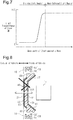
Fig. 7 is a graph showing the relationship between the wavelengths of electromagnetic waves and the light transmittance of the cover according to the second embodiment. -
Fig. 8 is an operation diagram of the cover device for a near-infrared sensor according to the second embodiment. -
Fig. 9 is an operation diagram of the cover device for a near-infrared sensor according to the second embodiment. -
Fig. 10 is a cross-sectional side view of a cover device for a near-infrared sensor according to another embodiment. -
Fig. 11 is a cross-sectional side view of a cover device for a near-infrared sensor according to another embodiment. - A cover device for a near-infrared sensor according to a first embodiment will now be described.
- As shown in
Figs. 1 and 2 , avehicle 10 has sets of a near-infrared sensor 11 and acover 20 provided at the four corners in a plan view (the right front corner, the left front corner, the right rear corner, and the left rear corner).Fig. 1 shows only thecover 20 provided in the left front corner of thevehicle 10. The near-infrared sensors 11 (Fig. 2 ) and the covers 20 in the four positions are identical. Thus, only the near-infrared sensor 11 and thecover 20 in the left front corner of thevehicle 10 will be described, and description of the other three near-infrared sensors 11 and thecorresponding covers 20 is omitted. - As shown in
Fig. 2 , the near-infrared sensor 11 has a substantially rectangular parallelepiped shape and is fixed to the body of thevehicle 10. Thecover 20 is an exterior component for thevehicle 10 and is a plate having a five-layer structure. Thecover 20 is fixed to the body of thevehicle 10. Thecover 20 is arranged to cover the near-infrared sensor 11 from the front side in the transmission direction of near-infrared light transmitted from the near-infrared sensor 11 (indicated by the blank arrow inFig. 2 ). The near-infrared light transmitted from the near-infrared sensor 11 passes through thecover 20 in the thickness direction (the left-right direction as viewed inFig. 2 ). - The
cover 20 includes areflection suppression layer 21, ahard coating layer 22, abase 23, a brightdecorative layer 24, and areflection suppression layer 25 in order from the side corresponding to the outside of the vehicle 10 (the left side inFig. 2 ). InFig. 2 , the thickness of the reflection suppression layers 21, 25, the thickness of thehard coating layer 22, and the thickness of the brightdecorative layer 24 are exaggerated in comparison with the actual thicknesses in order to facilitate understanding. - The
reflection suppression layer 21 is made of silicon dioxide having uniform and regular fine pores (mesoporous silica). Thereflection suppression layer 21 suppresses reflection of visible light (sunlight and the like) incident on thecover 20 from outside the vehicle (from the left side inFig. 2 ). - The
hard coating layer 22 is made of a hard plastic. Thehard coating layer 22 limits scratches on thecover 20 caused by contact with obstacles such as flying pebbles. Thehard coating layer 22 is formed by applying a surface treatment agent (for example, an acrylate-based hard coating agent) to the surface of thebase 23. - The
base 23 is made of a transparent plastic (polycarbonate). Thebase 23 constitutes the main part of thecover 20 in the thickness direction of thecover 20. - The bright
decorative layer 24 is made of a dielectric multilayer film that is formed by alternately laminating dielectric films made of a high refractive index material and dielectric films made of a low refractive index material, which has a relatively low refractive index. In the present embodiment, titanium dioxide [TiO2] is used as the high refractive index material. In the present embodiment, silicon dioxide [SiO2] is used as the low refractive index material. In the present embodiment, a total of twenty-five dielectric films are laminated together. - In general, a reflective film having a high reflectance is obtained by alternately stacking dielectric films having a high refractive index and dielectric films having a low refractive index. In the dielectric multilayer film, slight reflection occurs at the boundary between adjacent dielectric films. The thickness of each dielectric film in the dielectric multilayer film is adjusted to an optical path length of λ/4 (refractive index n x film thickness d). Accordingly, the phases of the rays reflected by the respective layers of the dielectric multilayer film are equalized, so that the rays reflected by the respective layers of the dielectric multilayer film intensify each other. In contrast, the rays of light that are multiply reflected in the dielectric multilayer film and advance in the transmission direction cancel out each other. Since light is scarcely absorbed by the dielectric multilayer film, the transmittance and the refractive index can be set in wide ranges. In the present embodiment, since the above-described dielectric multilayer film is employed, the bright
decorative layer 24 reflects part of the incident visible light and allows most of the remaining light to pass through, while allowing most of the incident near-infrared light to pass through. The wavelength of the incident visible light is in the range from 0.36 µm to 0.83 µm, and the wavelength of the incident near-infrared light is in the range from 0.83 µm to 3.00 µm. - In the present embodiment, the
cover 20 is configured such that the near-infrared light transmittance is higher than the visible light transmittance due to the above-described characteristics of the brightdecorative layer 24. Specifically, as shown inFig. 3 , the characteristics of the respective layers of the cover 20 (the material, structure, and shape) are determined such that the visible light transmittance (specifically, the transmittance of sunlight, which has wavelengths in the range from 0.40 µm to 0.70 µm) is 50%, and the near-infrared light transmittance is 90%. More specifically, thecover 20 is configured such that the average of the light transmittance in the wavelength region of sunlight (0.40 µm to 0.70 µm) is 50%. - As shown in
Fig. 2 , thereflection suppression layer 25 is made of mesoporous silica as in the case of thereflection suppression layer 21. Thereflection suppression layer 25 suppresses reflection of the near-infrared light transmitted from the near-infrared sensor 11 on thecover 20. - The
vehicle 10 includeslight emitting portions 30. Eachlight emitting portion 30 is located closer to the corresponding near-infrared sensor 11 than the corresponding cover 20 (on the right side of thecover 20 as viewed inFig. 2 ). Eachlight emitting portion 30 includes acase 31 having a shape of a closed loop and light emitting diodes 32 (only two of which are shown inFig. 2 ). Thecase 31 extends along the outer periphery of thecover 20. Thelight emitting diodes 32 are fixed to the bottom of thecase 31. Thecase 31 extends to have an opening facing the outer periphery of thecover 20 and is fixed to the body of thevehicle 10. Thelight emitting diodes 32 are accommodated in thecase 31 to be arranged at intervals along the outer periphery of thecover 20. When thelight emitting diodes 32 in thecase 31 are turned on, thelight emitting portion 30 emits visible light to the surface of thecover 20 on the side closer to the near-infrared sensor 11 (aback surface 20A). - The
vehicle 10 is provided with anelectronic control unit 12, which is mainly constituted by, for example, a microcomputer. Theelectronic control unit 12 is connected to various types of sensors that detect the driving state of thevehicle 10, operating switches for operating in-vehicle devices, and thelight emitting diodes 32 of thelight emitting portions 30. Theelectronic control unit 12 receives output signals of the sensors and the operating switches, executes calculations based on the signals, and controls operation (turning on/off) of the light emitting portions 30 (specifically, the light emitting diodes 32) based on the calculation result. - In the operation control of the
light emitting portions 30, thelight emitting diodes 32 may be turned on in conjunction with turning on of the headlights of thevehicle 10. For example, thelight emitting diodes 32 are turned on when the headlights are turned on, and thelight emitting diodes 32 are turned off when the headlights are turned off. In the operation control of thelight emitting portions 30 in a vehicle having a self-driving feature, thelight emitting diodes 32 may be turned on in conjunction with execution of self-driving operation. For example, thelight emitting diodes 32 are turned off when the self-driving operation is not executed, and are turned on when the self-driving operation is executed. - The operation and advantages of the cover device for a near-infrared sensor of the present embodiment will now be described.
- As shown in
Figs. 4 and5 , thevehicle 10 includes thecovers 20, each of which is arranged to cover the corresponding near-infrared sensor 11 from the front side in the transmission direction of near-infrared light transmitted from the near-infrared sensor 11 (indicated by the blank arrows inFigs. 4 and5 ). The near-infrared light transmittance of thecover 20 is set relatively high (90% in the present embodiment). Thus, the near-infrared light transmitted from the near-infrared sensor 11 and the near-infrared light that is reflected by an obstacle and returns pass through thecover 20. Since thecover 20 is prevented from hampering the transmission and reception of near-infrared light by the near-infrared sensor 11, the obstacle detecting function of the near-infrared sensor 11 is ensured. - In contrast, the transmittance of visible light (indicated by the solid arrows in
Figs. 4 and5 ) of thecover 20 of the present embodiment is set relatively low (in the present embodiment, the sunlight transmittance is 50%). - Thus, as indicated by the solid arrows in
Fig. 4 , when visible light (sunlight) is incident on thecover 20 from the outside of thevehicle 10, part of the sunlight is reflected by the surface of the brightdecorative layer 24 corresponding to the outside of thevehicle 10. This prevents the near-infrared sensor 11 from being easily seen from the outside of thevehicle 10. Therefore, the design of the part in which the near-infrared sensor 11 is provided is improved as compared to a case in which the near-infrared sensor 11 is attached to thevehicle 10 in an exposed state. In addition, thecover 20 is caused to shine using the reflection of the sunlight, which further improves the design of the part in which thecover 20 is provided. The color of thecover 20 when reflecting visible light (sunlight) and the color of the exterior component provided about the cover 20 (specifically, the bumper) may be the same color so that thecover 20 is inconspicuous. - As indicated by the solid arrows in
Fig. 5 , when thelight emitting diodes 32 are turned on to emit visible light to theback surface 20A of thecover 20, part of the emitted visible light passes through the brightdecorative layer 24 to cause the surface of thecover 20 that includes the brightdecorative layer 24 and corresponds to the outside of thevehicle 10 to shine. Thus, in the present embodiment, thelight emitting diodes 32 can be turned on at any time such as during night driving or automatic driving to cause thecover 20 to shine. This further improves the design of the part in which thecover 20 is provided. - In the
cover 20 of the present embodiment, the brightdecorative layer 24 is located closer to the near-infrared sensor 11 than the base 23, that is, on the side of thecover 20 of the multilayer structure that corresponds to the inner side of thevehicle 10. Therefore, thecover 20 is configured such that the brightdecorative layer 24 is unlikely to be scratched by obstacles from the outside of thevehicle 10 as compared to a case in which the brightdecorative layer 24 is located farther from the near-infrared sensor 11 than the base 23 (that is, a case in which the brightdecorative layer 24 is located on the side of the base 23 corresponding to the outside of the vehicle 10). Accordingly, the design of the brightdecorative layer 24 and the detection accuracy for obstacles are prevented from being deteriorated by scratches on the brightdecorative layer 24 in a favorable manner. - As described above, the present embodiment provides the following advantages.
- (1) The plate-shaped
cover 20 is arranged in thevehicle 10 such that near-infrared light transmitted from the near-infrared sensor 11 passes through thecover 20 in the thickness direction. A part of thecover 20 in the thickness direction is constituted by the brightdecorative layer 24, which reflects part of visible light and allows near-infrared light to pass through. Thecover 20 is configured such that the near-infrared light transmittance is higher than the sunlight transmittance. In addition, thelight emitting portion 30, which emits visible light to thecover 20, is provided. Accordingly, the design is further improved while ensuring the detection function of the near-infrared sensor 11. - (2) The bright
decorative layer 24 of thecover 20 is located closer to the near-infrared sensor 11 than the base 23 (that is, the brightdecorative layer 24 is located on the side of the base 23 that corresponds to the inner side of the vehicle 10). Accordingly, the design of the brightdecorative layer 24 and the detection accuracy for obstacles are prevented from being deteriorated by scratches on the brightdecorative layer 24. - (3) The
light emitting portion 30 is arranged to emit visible light to the surface of the brightdecorative layer 24 on the side closer to the near-infrared sensor 11. Since part of the visible light emitted by thelight emitting portion 30 passes through the brightdecorative layer 24, the passed-through visible light causes the brightdecorative layer 24 to shine. - A cover device for a near-infrared sensor according to a second embodiment will now be described. Differences from the first embodiment will be mainly discussed. The same reference numerals are given to those components of the same functions as those in the first embodiment, and detailed explanations are omitted.
- The present embodiment is different from the first embodiment mainly in the position in which the light emitting portion is arranged in relation to the cover. In the first embodiment, the light emitting portion 30 (refer to
Fig. 2 ) is arranged to emit visible light to the surface of the brightdecorative layer 24 on the side closer to the near-infrared sensor 11. In contrast, in the present embodiment, the light emitting portion is arranged to emit visible light to the surface of the bright decorative layer on the side farther from the near-infrared sensor 11. - A cover device for a near-infrared sensor according to the present embodiment will now be described.
- As shown in
Fig. 6 , acover 40 is a plate having a five-layer structure. Thecover 40 is an exterior component for avehicle 10 and is fixed to the body of thevehicle 10. Thecover 40 includes areflection suppression layer 21, ahard coating layer 22, abase 23, a brightdecorative layer 44, and areflection suppression layer 25 in order from the side corresponding to the outside of the vehicle 10 (the left side inFig. 6 ). InFig. 6 , the thickness of the reflection suppression layers 21, 25, the thickness of thehard coating layer 22, and the thickness of the brightdecorative layer 44 are exaggerated in comparison with the actual thicknesses in order to facilitate understanding. - The bright
decorative layer 44 of the present embodiment is made of a dielectric multilayer film that is formed by alternately laminating dielectric films made of a high refractive index material and dielectric films made of a low refractive index material, which has a relatively low refractive index. In the present embodiment, titanium dioxide [TiO2] is used as the high refractive index material. In the present embodiment, silicon dioxide [SiO2] is used as the low refractive index material. The brightdecorative layer 44 reflects part of the incident visible light and allows most of the remaining light to pass through, while allowing most of the incident near-infrared light to pass through. - In the present embodiment, the
cover 40 is configured such that the near-infrared light transmittance is higher than the visible light transmittance due to the above-described characteristics of the brightdecorative layer 44. Specifically, in the cover 40 (specifically, in the part where the brightdecorative layer 44 is provided), the characteristics of the respective layers of the cover 40 (the material, structure, and shape) are determined such that the visible light transmittance (specifically, the transmittance of sunlight, which has wavelengths in the range from 0.40 µm to 0.70 µm) is 5%, and the near-infrared light transmittance is 90% as shown inFig. 7 . More specifically, thecover 40 of the present embodiment is configured such that the average of the light transmittance in the wavelength region of sunlight (0.40 µm to 0.70 µm) is 5%. - The
cover 40 includes aninclined portion 47 on the outer peripheral edge. Theinclined portion 47 is inclined toward the near-infrared sensor 11 (toward the interior of the vehicle 10). Theinclined portion 47 hasprotrusion 48, which is provided by protruding parts of the base 23 outward. Theprotrusion 48 has a shape of a closed loop extending continuously over the entire circumference of theinclined portion 47. - The
vehicle 10 includes alight emitting portion 50, which has a shape of a closed loop continuously extending along the outer circumferential surface of the cover 40 (specifically, the protruding end of theprotrusion 48, which has a shape of a closed loop). Thelight emitting portion 50 includes acase 51 having a shape of a closed loop and light emitting diodes 32 (only two of which are shown inFig. 6 ). Thecase 51 extends along the protruding end of theprotrusion 48. Thelight emitting diodes 32 are fixed to the bottom of thecase 51. Thecase 51 extends to open toward the protruding end of theprotrusion 48 and is fixed to the body of thevehicle 10. Thelight emitting diodes 32 are accommodated in thecase 51 to be arranged at intervals along the outer circumferential surface of thecover 40. - When the
light emitting diodes 32 in thecase 51 are turned on, thelight emitting portion 50 emits visible light into the base 23 in thecover 40 via theprotrusion 48, specifically toward asurface 44A of the brightdecorative layer 44 on the side farther from the near-infrared sensor 11. - The operation and advantages of the cover device for a near-infrared sensor of the present embodiment will now be described.
- As shown in
Figs. 8 and9 , the present embodiment includes thecover 40, which is arranged to cover a near-infrared sensor 11 from the front side in the transmission direction of near-infrared light transmitted from the near-infrared sensor 11 (indicated by the blank arrows inFigs. 8 and9 ). The near-infrared light transmittance of thecover 40 is set relatively high (90% in the present embodiment). Thus, the near-infrared light transmitted from the near-infrared sensor 11 and the near-infrared light that is reflected by an obstacle and returns pass through thecover 40. Since thecover 40 is prevented from hampering the transmission and reception of near-infrared light by the near-infrared sensor 11, the obstacle detecting function of the near-infrared sensor 11 is ensured. - In contrast, the transmittance of visible light (indicated by the solid arrows in
Figs. 8 and9 ) of thecover 40 of the present embodiment is set relatively low (in the present embodiment, the sunlight transmittance is 5%). - Thus, as indicated by the solid arrows in
Fig. 8 , when visible light (sunlight) is incident on thecover 40 from the outside of thevehicle 10, part of the sunlight is reflected by thesurface 44A of the brightdecorative layer 44 corresponding to the outside of thevehicle 10. This prevents the near-infrared sensor 11 from being easily seen from the outside of thevehicle 10. Therefore, the design of the part in which the near-infrared sensor 11 is provided is improved as compared to a case in which the near-infrared sensor 11 is attached to thevehicle 10 in an exposed state. In addition, thecover 40 is caused to shine using the reflection of the sunlight, which further improves the design of the part in which thecover 40 is provided. - As indicated by the solid arrows in
Fig. 9 , when thelight emitting diodes 32 are turned on so that visible light is emitted from thelight emitting portion 50 toward thecover 40, the visible light reaches thesurface 44A of the brightdecorative layer 44 on the side farther from the near-infrared sensor 11 (the side corresponding to the outside of the vehicle 10) via theprotrusion 48 and thebase 23. Part of the visible light reaching thesurface 44A on the side corresponding to the outside of thevehicle 10 is reflected by thesurface 44A, so that thesurface 44A shines. In addition, since the emitted visible light passes through the inside of thebase 23, which functions as a light guide, thebase 23 shines as the light passes through thebase 23. Thus, in the present embodiment, thelight emitting diodes 32 can be turned on at any time such as during night driving or automatic driving to cause thecover 40 to shine. This further improves the design of the part in which thecover 40 is provided. - In addition to the advantages (1) and (2) of the first embodiment, the present embodiment has the following advantage (4).
- (4) The
light emitting portion 50 is arranged to emit visible light to thesurface 44A of the brightdecorative layer 44 on the side farther from the near-infrared sensor 11 (the side corresponding to the outside of the vehicle 10). Thus, since part of the visible light emitted by thelight emitting portion 50 is reflected by thesurface 44A of the brightdecorative layer 44 corresponding to the outside of thevehicle 10, the reflected visible light causes the brightdecorative layer 44 to shine. - The above embodiments may be modified as follows.
- A cover may be employed in which the bright
decorative layer infrared sensor 11 than the base 23 (that is, the brightdecorative layer decorative layer vehicle 10. This allows the brightdecorative layer vehicle 10 as compared to a case in which the brightdecorative layer infrared sensor 11 than the base 23 (that is, a case in which the brightdecorative layer decorative layer Figs. 10 and11 illustrate concreate examples of such a cover device for a near-infrared sensor. - The example shown in
Fig. 10 includes acover 60 that is a plate having a five-layer structure. The same reference numerals are given to those components of the same functions as those in the first embodiment (seeFig. 2 ), and detailed explanations are omitted. InFig. 10 , the thickness of the reflection suppression layers 21, 25, the thickness of thehard coating layer 22, and the thickness of the brightdecorative layer 24 are exaggerated in comparison with the actual thicknesses in order to facilitate understanding. Thecover 60 includes areflection suppression layer 21, ahard coating layer 22, a brightdecorative layer 24, abase 23, and areflection suppression layer 25 in order from the side corresponding to the outside of the vehicle 10 (the left side inFig. 10 ). Thelight emitting portion 30 is provided to emit visible light on the back surface of thecover 60. In this case, the near-infrared light transmittance of thecover 60 is preferably set to 90%, and the light transmittance of sunlight of thecover 60 is preferably set to 50%. This configuration has advantages similar to the advantages (1) and (3) described above. - The example shown in
Fig. 11 includes acover 70 that is a plate having a five-layer structure. The same reference numerals are given to those components of the same functions as those in the second embodiment (seeFig. 6 ), and detailed explanations are omitted. InFig. 11 , the thickness of the reflection suppression layers 21, 25, the thickness of thehard coating layer 22, and the thickness of the brightdecorative layer 44 are exaggerated in comparison with the actual thicknesses in order to facilitate understanding. Thecover 70 includes areflection suppression layer 21, ahard coating layer 22, a brightdecorative layer 44, abase 23, and areflection suppression layer 25 in order from the side corresponding to the outside of the vehicle 10 (the left side inFig. 11 ). Thelight emitting portion 50 is provided to emit visible light on the protruding end of aprotrusion 48 arranged on the outer circumference of thecover 70. In this case, the near-infrared light transmittance of thecover 70 is preferably set to 90%, and the light transmittance of sunlight of thecover 70 is preferably set to 50%. - In addition to advantages similar to the advantage (1) described above, this configuration has the following advantages. When the
light emitting diodes 32 are turned on so that visible light is emitted from thelight emitting portion 50 toward thecover 70, the visible light passes through the inside of thebase 23. Since part of the visible light passing through the inside of the base 23 passes through the brightdecorative layer 44, the surface of the brightdecorative layer 44 on the side corresponding to the outside of the vehicle 10 (the left side inFig. 11 ) shines. Thus, thelight emitting diodes 32 can be turned on at any time such as during night driving or automatic driving to cause thecover 70 to shine. This further improves the design of the part in which thecover 70 is provided. - The high refractive index material and the low refractive index material that are used to form the dielectric films constituting the bright
decorative layers - The near-infrared light transmittance and the visible light transmittance of the
covers infrared sensor 11 and higher than the visible light transmittance (specifically, the transmittance of visible light in most of the wavelength regions except for visible light of wavelengths in the vicinity of the boundary with the near-infrared light range). Various experiments and simulations conducted by the inventors have revealed the following. In order to improve the design of thecovers infrared sensor 11, the transmittance of visible light in most of the wavelength regions is preferably set to the range from 5% to 50%. - The
light emitting diodes 32 of thelight emitting portions - The
light emitting diodes 32 may be replaced by another type of light emitters such as incandescent lamps. - The reflection suppression layers 21, 25 may be made of a material other than mesoporous silica. Such a material may be an antireflection film having a moth-eye structure ("moth-eye film") or a dielectric film having a single layer structure or a multilayer structure.
- The
hard coating layer 22 may be omitted. - The reflection suppression layers 21, 25 may be omitted.
- The material for the base 23 may be polymethyl methacrylate (PMMA) or cycloolefin polymer (COP) . The base 23 may be made of a translucent plastic.
- 10...Vehicle; 11...Near-Infrared Sensor; 12...Electronic Control Unit; 20, 40, 60, 70...Cover; 20A...Back Surface; 21...Reflection Suppression Layer; 22...Hard Coating Layer; 23...Base; 24, 44...Bright Decorative Layer; 44A...Surface; 25...Reflection Suppression Layer; 30, 50...Light Emitting Portion; 31, 51...Case; 32...Light Emitting Diode; 44...Bright Decorative Layer; 47...Inclined Portion; 48...Protrusion
Claims (6)
- A cover device for a near-infrared sensor, the cover device being arranged to cover a near-infrared sensor from a front side in a transmission direction of near-infrared light transmitted from the near-infrared sensor, the cover device comprising:a plate shaped cover, whereinthe cover is arranged in a vehicle such that near-infrared light transmitted from the near-infrared sensor passes through the cover in a thickness direction of the cover,a part of the cover in the thickness direction is constituted by a bright decorative layer, which reflects part of incident visible light and allows near-infrared light to pass through, andthe cover is configured such that a near-infrared light transmittance is higher than a visible light transmittance; anda light emitting portion that emits visible light to the cover.
- The cover device for a near-infrared sensor according to claim 1, wherein the visible light transmittance of the cover is higher than or equal to 5% and lower than or equal to 50%.
- The cover device for a near-infrared sensor according to claim 1 or 2, wherein
a main part of the cover in the thickness direction is constituted by a transparent or translucent base, and
the bright decorative layer is located closer to the near-infrared sensor than the base. - The cover device for a near-infrared sensor according to claim 1 or 2, wherein
a main part of the cover in the thickness direction is constituted by a transparent or translucent base, and
the bright decorative layer is located farther from the near-infrared sensor than the base. - The cover device for a near-infrared sensor according to any one of claims 1 to 4, wherein the light emitting portion is arranged to emit the visible light to a surface of the bright decorative layer on a side closer to the near-infrared sensor.
- The cover device for a near-infrared sensor according to any one of claims 1 to 4, wherein the light emitting portion is arranged to emit the visible light to a surface of the bright decorative layer on a side farther from the near-infrared sensor.
Applications Claiming Priority (2)
| Application Number | Priority Date | Filing Date | Title |
|---|---|---|---|
| JP2017182772A JP6812936B2 (en) | 2017-09-22 | 2017-09-22 | Cover device for near infrared sensor |
| PCT/JP2018/030710 WO2019058834A1 (en) | 2017-09-22 | 2018-08-20 | Cover device for near-infrared sensors |
Publications (3)
| Publication Number | Publication Date |
|---|---|
| EP3663814A1 true EP3663814A1 (en) | 2020-06-10 |
| EP3663814A4 EP3663814A4 (en) | 2021-05-05 |
| EP3663814B1 EP3663814B1 (en) | 2023-08-09 |
Family
ID=65811089
Family Applications (1)
| Application Number | Title | Priority Date | Filing Date |
|---|---|---|---|
| EP18858249.8A Active EP3663814B1 (en) | 2017-09-22 | 2018-08-20 | Cover device for near-infrared sensors |
Country Status (5)
| Country | Link |
|---|---|
| US (1) | US11385176B2 (en) |
| EP (1) | EP3663814B1 (en) |
| JP (1) | JP6812936B2 (en) |
| CN (1) | CN111095049B (en) |
| WO (1) | WO2019058834A1 (en) |
Cited By (1)
| Publication number | Priority date | Publication date | Assignee | Title |
|---|---|---|---|---|
| WO2020247292A1 (en) * | 2019-06-05 | 2020-12-10 | Corning Incorporated | Hardened optical windows with anti-reflective, reflective, and absorbing layers for infrared sensing systems |
Families Citing this family (21)
| Publication number | Priority date | Publication date | Assignee | Title |
|---|---|---|---|---|
| CN110049826B (en) * | 2016-12-15 | 2023-11-24 | 科思创德国股份有限公司 | Clear coated polycarbonate parts, their manufacture and uses |
| GB201812121D0 (en) * | 2018-07-25 | 2018-09-05 | Aqualand Industries Ltd | Improvements to a vehicle |
| JP7242261B2 (en) * | 2018-11-14 | 2023-03-20 | 豊田合成株式会社 | Infrared transmission cover |
| JP7132887B2 (en) * | 2019-05-29 | 2022-09-07 | 本田技研工業株式会社 | vehicle light body |
| WO2020247245A1 (en) | 2019-06-05 | 2020-12-10 | Corning Incorporated | Hardened optical windows for lidar applications at 850-950nm |
| FR3100870B1 (en) | 2019-09-16 | 2022-01-14 | Valeo Vision | Light device of a vehicle |
| EP4042185A1 (en) * | 2019-10-11 | 2022-08-17 | AGC Glass Europe | Lidar detection device provided with a laminated protective layer |
| JP7524530B2 (en) * | 2019-11-19 | 2024-07-30 | 大日本印刷株式会社 | Infrared Sensor |
| JP6892002B2 (en) * | 2019-11-19 | 2021-06-18 | 大日本印刷株式会社 | Resin panel and infrared sensor |
| CN112526478A (en) * | 2019-11-22 | 2021-03-19 | 宁波舜宇车载光学技术有限公司 | Composite protection device and manufacturing method thereof, outer cover and laser radar device |
| JP7230830B2 (en) * | 2020-01-16 | 2023-03-01 | 豊田合成株式会社 | Near-infrared sensor cover |
| JP7538607B2 (en) * | 2020-03-06 | 2024-08-22 | 株式会社小糸製作所 | Sensor unit and lighting device |
| JP7461598B2 (en) * | 2020-03-24 | 2024-04-04 | 豊田合成株式会社 | Lighting cover |
| JP7528729B2 (en) * | 2020-11-10 | 2024-08-06 | 東レ株式会社 | film |
| JP7392676B2 (en) * | 2021-02-24 | 2023-12-06 | 豊田合成株式会社 | Electromagnetic wave sensor cover |
| JP7590223B2 (en) * | 2021-03-08 | 2024-11-26 | 本田技研工業株式会社 | Body structure with external sensors |
| EP4105678A1 (en) * | 2021-06-18 | 2022-12-21 | HELLA Saturnus Slovenija d.o.o. | Illuminated cover for electromagnetic transmitter and receiver |
| TW202436910A (en) * | 2022-10-07 | 2024-09-16 | 美商康寧公司 | Hardened optical windows with anti-reflective films having low visible reflectance and transmission for infrared sensing systems |
| JP2024074129A (en) * | 2022-11-18 | 2024-05-30 | 豊田合成株式会社 | Electromagnetic wave transparent cover and sensor module |
| JP2025016118A (en) * | 2023-07-21 | 2025-01-31 | 豊田合成株式会社 | Exterior structure and vehicular exterior structure |
| US11965631B1 (en) * | 2023-08-15 | 2024-04-23 | Sl Corporation | Lamp for vehicle |
Family Cites Families (18)
| Publication number | Priority date | Publication date | Assignee | Title |
|---|---|---|---|---|
| US5339198A (en) * | 1992-10-16 | 1994-08-16 | The Dow Chemical Company | All-polymeric cold mirror |
| JP4627610B2 (en) * | 2001-06-19 | 2011-02-09 | 株式会社ファルテック | Infrared sensor cover and infrared sensor unit using the same |
| JP3646930B2 (en) * | 2001-07-30 | 2005-05-11 | 日産自動車株式会社 | Infrared sensor cover and infrared sensor unit using the same |
| US7206125B2 (en) * | 2003-11-10 | 2007-04-17 | Therma-Wave, Inc. | Infrared blocking filter for broadband Optical metrology |
| JP2006117048A (en) * | 2004-10-20 | 2006-05-11 | Toyota Motor Corp | Bright decorative molded product and molded product for radar device beam path |
| JP4122010B2 (en) * | 2004-11-12 | 2008-07-23 | 東海光学株式会社 | Infrared light emitter / receiver |
| CN101057341B (en) * | 2004-11-12 | 2010-12-29 | 东海光学株式会社 | Infrared ray transmission cover |
| US7786898B2 (en) * | 2006-05-31 | 2010-08-31 | Mobileye Technologies Ltd. | Fusion of far infrared and visible images in enhanced obstacle detection in automotive applications |
| GB2453484B (en) * | 2006-07-27 | 2009-12-02 | Visonic Ltd | Passive infrared detectors |
| JP5132656B2 (en) * | 2009-10-28 | 2013-01-30 | サカエ理研工業株式会社 | Lighting device for decorative member |
| CN201910121U (en) * | 2010-04-02 | 2011-07-27 | 杭州浙力叉车集团有限公司 | Device for reminding user of approaching object around |
| JP2014070899A (en) * | 2012-09-27 | 2014-04-21 | Toyoda Gosei Co Ltd | Millimeter wave radar apparatus for vehicle use |
| JP6091009B2 (en) * | 2012-11-29 | 2017-03-08 | 富士フイルム株式会社 | Composition, colored layer, infrared transmission filter and method for producing the same, infrared sensor, and color filter |
| JP5994686B2 (en) * | 2013-03-07 | 2016-09-21 | 旭硝子株式会社 | Optical glass |
| JP6202028B2 (en) | 2015-03-24 | 2017-09-27 | トヨタ自動車株式会社 | Arrangement structure of surrounding information detection sensor and autonomous driving vehicle |
| JP6646451B2 (en) * | 2016-01-14 | 2020-02-14 | 株式会社ジャパンディスプレイ | Cover member and display device having the same |
| KR102626262B1 (en) * | 2016-01-21 | 2024-01-16 | 쓰리엠 이노베이티브 프로퍼티즈 컴파니 | optical camouflage filters |
| WO2018052057A1 (en) * | 2016-09-15 | 2018-03-22 | 豊田合成 株式会社 | Near infrared sensor cover |
-
2017
- 2017-09-22 JP JP2017182772A patent/JP6812936B2/en active Active
-
2018
- 2018-08-20 CN CN201880059952.7A patent/CN111095049B/en active Active
- 2018-08-20 US US16/640,167 patent/US11385176B2/en active Active
- 2018-08-20 EP EP18858249.8A patent/EP3663814B1/en active Active
- 2018-08-20 WO PCT/JP2018/030710 patent/WO2019058834A1/en not_active Ceased
Cited By (2)
| Publication number | Priority date | Publication date | Assignee | Title |
|---|---|---|---|---|
| WO2020247292A1 (en) * | 2019-06-05 | 2020-12-10 | Corning Incorporated | Hardened optical windows with anti-reflective, reflective, and absorbing layers for infrared sensing systems |
| US12481028B2 (en) | 2019-06-05 | 2025-11-25 | Corning Incorporated | Hardened optical windows with anti-reflective, reflective, and absorbing layers for infrared sensing systems |
Also Published As
| Publication number | Publication date |
|---|---|
| US11385176B2 (en) | 2022-07-12 |
| CN111095049A (en) | 2020-05-01 |
| EP3663814A4 (en) | 2021-05-05 |
| WO2019058834A1 (en) | 2019-03-28 |
| JP2019057481A (en) | 2019-04-11 |
| US20200363329A1 (en) | 2020-11-19 |
| EP3663814B1 (en) | 2023-08-09 |
| JP6812936B2 (en) | 2021-01-13 |
| CN111095049B (en) | 2022-05-24 |
Similar Documents
| Publication | Publication Date | Title |
|---|---|---|
| EP3663814B1 (en) | Cover device for near-infrared sensors | |
| US7538734B2 (en) | Vehicle decorative component | |
| KR102649667B1 (en) | Vehicle window with integrated sensor module | |
| US11199610B2 (en) | Onboard sensor cover | |
| WO2018052057A1 (en) | Near infrared sensor cover | |
| KR102565730B1 (en) | Motor vehicle lighting device | |
| JP4974115B2 (en) | Radio transmission / reception device for vehicles | |
| JP2009126223A (en) | Rear view mirror with light emitting display device | |
| CN109856613B (en) | Laser radar cover | |
| JP6294326B2 (en) | Lighting glass panel | |
| JP2024070252A (en) | Radome for vehicle | |
| US12539808B2 (en) | Vehicle exterior component and exterior structure of vehicle | |
| US12565142B2 (en) | Exterior structure, vehicle exterior structure, and method for controlling exterior structure | |
| US20240217314A1 (en) | Front windshield and automobile | |
| JP6485801B2 (en) | Vehicle lighting | |
| US20230141051A1 (en) | Sensor Device | |
| JP7731234B2 (en) | Vehicle exterior parts | |
| US11976796B2 (en) | Motor vehicle lighting device | |
| US20260063766A1 (en) | Infrared sensor cover | |
| JP2976679B2 (en) | Inter-vehicle distance detection device | |
| WO2006103575A1 (en) | Translucent wall element and motor vehicle comprising such an element | |
| US12264799B2 (en) | Display device | |
| JP2019219690A (en) | Near infrared sensor cover | |
| JP2026003711A (en) | Motorcycle Windshield Display System | |
| JP2026046997A (en) | Infrared sensor cover |
Legal Events
| Date | Code | Title | Description |
|---|---|---|---|
| STAA | Information on the status of an ep patent application or granted ep patent |
Free format text: STATUS: THE INTERNATIONAL PUBLICATION HAS BEEN MADE |
|
| PUAI | Public reference made under article 153(3) epc to a published international application that has entered the european phase |
Free format text: ORIGINAL CODE: 0009012 |
|
| STAA | Information on the status of an ep patent application or granted ep patent |
Free format text: STATUS: REQUEST FOR EXAMINATION WAS MADE |
|
| 17P | Request for examination filed |
Effective date: 20200305 |
|
| AK | Designated contracting states |
Kind code of ref document: A1 Designated state(s): AL AT BE BG CH CY CZ DE DK EE ES FI FR GB GR HR HU IE IS IT LI LT LU LV MC MK MT NL NO PL PT RO RS SE SI SK SM TR |
|
| AX | Request for extension of the european patent |
Extension state: BA ME |
|
| DAV | Request for validation of the european patent (deleted) | ||
| DAX | Request for extension of the european patent (deleted) | ||
| A4 | Supplementary search report drawn up and despatched |
Effective date: 20210406 |
|
| RIC1 | Information provided on ipc code assigned before grant |
Ipc: G02B 5/26 20060101AFI20210329BHEP Ipc: B60R 13/04 20060101ALI20210329BHEP Ipc: F21S 43/20 20180101ALI20210329BHEP Ipc: G01S 7/481 20060101ALI20210329BHEP Ipc: G02B 5/28 20060101ALI20210329BHEP Ipc: F21Y 115/10 20160101ALI20210329BHEP Ipc: G02B 5/20 20060101ALI20210329BHEP Ipc: G01J 5/04 20060101ALI20210329BHEP |
|
| GRAP | Despatch of communication of intention to grant a patent |
Free format text: ORIGINAL CODE: EPIDOSNIGR1 |
|
| STAA | Information on the status of an ep patent application or granted ep patent |
Free format text: STATUS: GRANT OF PATENT IS INTENDED |
|
| INTG | Intention to grant announced |
Effective date: 20230504 |
|
| RIN1 | Information on inventor provided before grant (corrected) |
Inventor name: TANAKA, YOSHIHARU Inventor name: FUKUI, HIROTAKA Inventor name: ANDO, HIROAKI Inventor name: OKAWA, SHINTAROU Inventor name: OKUMURA, KOJI |
|
| GRAS | Grant fee paid |
Free format text: ORIGINAL CODE: EPIDOSNIGR3 |
|
| GRAA | (expected) grant |
Free format text: ORIGINAL CODE: 0009210 |
|
| STAA | Information on the status of an ep patent application or granted ep patent |
Free format text: STATUS: THE PATENT HAS BEEN GRANTED |
|
| AK | Designated contracting states |
Kind code of ref document: B1 Designated state(s): AL AT BE BG CH CY CZ DE DK EE ES FI FR GB GR HR HU IE IS IT LI LT LU LV MC MK MT NL NO PL PT RO RS SE SI SK SM TR |
|
| REG | Reference to a national code |
Ref country code: GB Ref legal event code: FG4D |
|
| REG | Reference to a national code |
Ref country code: CH Ref legal event code: EP |
|
| REG | Reference to a national code |
Ref country code: IE Ref legal event code: FG4D |
|
| REG | Reference to a national code |
Ref country code: DE Ref legal event code: R096 Ref document number: 602018055187 Country of ref document: DE |
|
| REG | Reference to a national code |
Ref country code: LT Ref legal event code: MG9D |
|
| REG | Reference to a national code |
Ref country code: NL Ref legal event code: MP Effective date: 20230809 |
|
| REG | Reference to a national code |
Ref country code: AT Ref legal event code: MK05 Ref document number: 1598174 Country of ref document: AT Kind code of ref document: T Effective date: 20230809 |
|
| PG25 | Lapsed in a contracting state [announced via postgrant information from national office to epo] |
Ref country code: GR Free format text: LAPSE BECAUSE OF FAILURE TO SUBMIT A TRANSLATION OF THE DESCRIPTION OR TO PAY THE FEE WITHIN THE PRESCRIBED TIME-LIMIT Effective date: 20231110 |
|
| PG25 | Lapsed in a contracting state [announced via postgrant information from national office to epo] |
Ref country code: IS Free format text: LAPSE BECAUSE OF FAILURE TO SUBMIT A TRANSLATION OF THE DESCRIPTION OR TO PAY THE FEE WITHIN THE PRESCRIBED TIME-LIMIT Effective date: 20231209 |
|
| PG25 | Lapsed in a contracting state [announced via postgrant information from national office to epo] |
Ref country code: SE Free format text: LAPSE BECAUSE OF FAILURE TO SUBMIT A TRANSLATION OF THE DESCRIPTION OR TO PAY THE FEE WITHIN THE PRESCRIBED TIME-LIMIT Effective date: 20230809 Ref country code: RS Free format text: LAPSE BECAUSE OF FAILURE TO SUBMIT A TRANSLATION OF THE DESCRIPTION OR TO PAY THE FEE WITHIN THE PRESCRIBED TIME-LIMIT Effective date: 20230809 Ref country code: PT Free format text: LAPSE BECAUSE OF FAILURE TO SUBMIT A TRANSLATION OF THE DESCRIPTION OR TO PAY THE FEE WITHIN THE PRESCRIBED TIME-LIMIT Effective date: 20231211 Ref country code: NO Free format text: LAPSE BECAUSE OF FAILURE TO SUBMIT A TRANSLATION OF THE DESCRIPTION OR TO PAY THE FEE WITHIN THE PRESCRIBED TIME-LIMIT Effective date: 20231109 Ref country code: NL Free format text: LAPSE BECAUSE OF FAILURE TO SUBMIT A TRANSLATION OF THE DESCRIPTION OR TO PAY THE FEE WITHIN THE PRESCRIBED TIME-LIMIT Effective date: 20230809 Ref country code: LV Free format text: LAPSE BECAUSE OF FAILURE TO SUBMIT A TRANSLATION OF THE DESCRIPTION OR TO PAY THE FEE WITHIN THE PRESCRIBED TIME-LIMIT Effective date: 20230809 Ref country code: LT Free format text: LAPSE BECAUSE OF FAILURE TO SUBMIT A TRANSLATION OF THE DESCRIPTION OR TO PAY THE FEE WITHIN THE PRESCRIBED TIME-LIMIT Effective date: 20230809 Ref country code: IS Free format text: LAPSE BECAUSE OF FAILURE TO SUBMIT A TRANSLATION OF THE DESCRIPTION OR TO PAY THE FEE WITHIN THE PRESCRIBED TIME-LIMIT Effective date: 20231209 Ref country code: HR Free format text: LAPSE BECAUSE OF FAILURE TO SUBMIT A TRANSLATION OF THE DESCRIPTION OR TO PAY THE FEE WITHIN THE PRESCRIBED TIME-LIMIT Effective date: 20230809 Ref country code: GR Free format text: LAPSE BECAUSE OF FAILURE TO SUBMIT A TRANSLATION OF THE DESCRIPTION OR TO PAY THE FEE WITHIN THE PRESCRIBED TIME-LIMIT Effective date: 20231110 Ref country code: FI Free format text: LAPSE BECAUSE OF FAILURE TO SUBMIT A TRANSLATION OF THE DESCRIPTION OR TO PAY THE FEE WITHIN THE PRESCRIBED TIME-LIMIT Effective date: 20230809 Ref country code: AT Free format text: LAPSE BECAUSE OF FAILURE TO SUBMIT A TRANSLATION OF THE DESCRIPTION OR TO PAY THE FEE WITHIN THE PRESCRIBED TIME-LIMIT Effective date: 20230809 |
|
| PG25 | Lapsed in a contracting state [announced via postgrant information from national office to epo] |
Ref country code: PL Free format text: LAPSE BECAUSE OF FAILURE TO SUBMIT A TRANSLATION OF THE DESCRIPTION OR TO PAY THE FEE WITHIN THE PRESCRIBED TIME-LIMIT Effective date: 20230809 |
|
| REG | Reference to a national code |
Ref country code: CH Ref legal event code: PL |
|
| PG25 | Lapsed in a contracting state [announced via postgrant information from national office to epo] |
Ref country code: LU Free format text: LAPSE BECAUSE OF NON-PAYMENT OF DUE FEES Effective date: 20230820 |
|
| PG25 | Lapsed in a contracting state [announced via postgrant information from national office to epo] |
Ref country code: ES Free format text: LAPSE BECAUSE OF FAILURE TO SUBMIT A TRANSLATION OF THE DESCRIPTION OR TO PAY THE FEE WITHIN THE PRESCRIBED TIME-LIMIT Effective date: 20230809 |
|
| PG25 | Lapsed in a contracting state [announced via postgrant information from national office to epo] |
Ref country code: SM Free format text: LAPSE BECAUSE OF FAILURE TO SUBMIT A TRANSLATION OF THE DESCRIPTION OR TO PAY THE FEE WITHIN THE PRESCRIBED TIME-LIMIT Effective date: 20230809 Ref country code: RO Free format text: LAPSE BECAUSE OF FAILURE TO SUBMIT A TRANSLATION OF THE DESCRIPTION OR TO PAY THE FEE WITHIN THE PRESCRIBED TIME-LIMIT Effective date: 20230809 Ref country code: LU Free format text: LAPSE BECAUSE OF NON-PAYMENT OF DUE FEES Effective date: 20230820 Ref country code: ES Free format text: LAPSE BECAUSE OF FAILURE TO SUBMIT A TRANSLATION OF THE DESCRIPTION OR TO PAY THE FEE WITHIN THE PRESCRIBED TIME-LIMIT Effective date: 20230809 Ref country code: EE Free format text: LAPSE BECAUSE OF FAILURE TO SUBMIT A TRANSLATION OF THE DESCRIPTION OR TO PAY THE FEE WITHIN THE PRESCRIBED TIME-LIMIT Effective date: 20230809 Ref country code: DK Free format text: LAPSE BECAUSE OF FAILURE TO SUBMIT A TRANSLATION OF THE DESCRIPTION OR TO PAY THE FEE WITHIN THE PRESCRIBED TIME-LIMIT Effective date: 20230809 Ref country code: CZ Free format text: LAPSE BECAUSE OF FAILURE TO SUBMIT A TRANSLATION OF THE DESCRIPTION OR TO PAY THE FEE WITHIN THE PRESCRIBED TIME-LIMIT Effective date: 20230809 Ref country code: CH Free format text: LAPSE BECAUSE OF NON-PAYMENT OF DUE FEES Effective date: 20230831 Ref country code: SK Free format text: LAPSE BECAUSE OF FAILURE TO SUBMIT A TRANSLATION OF THE DESCRIPTION OR TO PAY THE FEE WITHIN THE PRESCRIBED TIME-LIMIT Effective date: 20230809 |
|
| REG | Reference to a national code |
Ref country code: BE Ref legal event code: MM Effective date: 20230831 |
|
| REG | Reference to a national code |
Ref country code: DE Ref legal event code: R097 Ref document number: 602018055187 Country of ref document: DE |
|
| REG | Reference to a national code |
Ref country code: IE Ref legal event code: MM4A |
|
| PG25 | Lapsed in a contracting state [announced via postgrant information from national office to epo] |
Ref country code: IT Free format text: LAPSE BECAUSE OF FAILURE TO SUBMIT A TRANSLATION OF THE DESCRIPTION OR TO PAY THE FEE WITHIN THE PRESCRIBED TIME-LIMIT Effective date: 20230809 Ref country code: MC Free format text: LAPSE BECAUSE OF FAILURE TO SUBMIT A TRANSLATION OF THE DESCRIPTION OR TO PAY THE FEE WITHIN THE PRESCRIBED TIME-LIMIT Effective date: 20230809 |
|
| PLBE | No opposition filed within time limit |
Free format text: ORIGINAL CODE: 0009261 |
|
| STAA | Information on the status of an ep patent application or granted ep patent |
Free format text: STATUS: NO OPPOSITION FILED WITHIN TIME LIMIT |
|
| PG25 | Lapsed in a contracting state [announced via postgrant information from national office to epo] |
Ref country code: IE Free format text: LAPSE BECAUSE OF NON-PAYMENT OF DUE FEES Effective date: 20230820 |
|
| 26N | No opposition filed |
Effective date: 20240513 |
|
| GBPC | Gb: european patent ceased through non-payment of renewal fee |
Effective date: 20231109 |
|
| PG25 | Lapsed in a contracting state [announced via postgrant information from national office to epo] |
Ref country code: IE Free format text: LAPSE BECAUSE OF NON-PAYMENT OF DUE FEES Effective date: 20230820 Ref country code: FR Free format text: LAPSE BECAUSE OF NON-PAYMENT OF DUE FEES Effective date: 20231009 Ref country code: SI Free format text: LAPSE BECAUSE OF FAILURE TO SUBMIT A TRANSLATION OF THE DESCRIPTION OR TO PAY THE FEE WITHIN THE PRESCRIBED TIME-LIMIT Effective date: 20230809 |
|
| PG25 | Lapsed in a contracting state [announced via postgrant information from national office to epo] |
Ref country code: BE Free format text: LAPSE BECAUSE OF NON-PAYMENT OF DUE FEES Effective date: 20230831 |
|
| PG25 | Lapsed in a contracting state [announced via postgrant information from national office to epo] |
Ref country code: GB Free format text: LAPSE BECAUSE OF NON-PAYMENT OF DUE FEES Effective date: 20231109 |
|
| PG25 | Lapsed in a contracting state [announced via postgrant information from national office to epo] |
Ref country code: GB Free format text: LAPSE BECAUSE OF NON-PAYMENT OF DUE FEES Effective date: 20231109 |
|
| PG25 | Lapsed in a contracting state [announced via postgrant information from national office to epo] |
Ref country code: BG Free format text: LAPSE BECAUSE OF FAILURE TO SUBMIT A TRANSLATION OF THE DESCRIPTION OR TO PAY THE FEE WITHIN THE PRESCRIBED TIME-LIMIT Effective date: 20230809 |
|
| PG25 | Lapsed in a contracting state [announced via postgrant information from national office to epo] |
Ref country code: BG Free format text: LAPSE BECAUSE OF FAILURE TO SUBMIT A TRANSLATION OF THE DESCRIPTION OR TO PAY THE FEE WITHIN THE PRESCRIBED TIME-LIMIT Effective date: 20230809 |
|
| PG25 | Lapsed in a contracting state [announced via postgrant information from national office to epo] |
Ref country code: CY Free format text: LAPSE BECAUSE OF FAILURE TO SUBMIT A TRANSLATION OF THE DESCRIPTION OR TO PAY THE FEE WITHIN THE PRESCRIBED TIME-LIMIT; INVALID AB INITIO Effective date: 20180820 |
|
| PG25 | Lapsed in a contracting state [announced via postgrant information from national office to epo] |
Ref country code: HU Free format text: LAPSE BECAUSE OF FAILURE TO SUBMIT A TRANSLATION OF THE DESCRIPTION OR TO PAY THE FEE WITHIN THE PRESCRIBED TIME-LIMIT; INVALID AB INITIO Effective date: 20180820 |
|
| PGFP | Annual fee paid to national office [announced via postgrant information from national office to epo] |
Ref country code: DE Payment date: 20250702 Year of fee payment: 8 |
|
| PG25 | Lapsed in a contracting state [announced via postgrant information from national office to epo] |
Ref country code: TR Free format text: LAPSE BECAUSE OF FAILURE TO SUBMIT A TRANSLATION OF THE DESCRIPTION OR TO PAY THE FEE WITHIN THE PRESCRIBED TIME-LIMIT Effective date: 20230809 |