EP3663795A1 - Distance detection method and device for cleaning robot, and cleaning robot - Google Patents
Distance detection method and device for cleaning robot, and cleaning robot Download PDFInfo
- Publication number
- EP3663795A1 EP3663795A1 EP19214006.9A EP19214006A EP3663795A1 EP 3663795 A1 EP3663795 A1 EP 3663795A1 EP 19214006 A EP19214006 A EP 19214006A EP 3663795 A1 EP3663795 A1 EP 3663795A1
- Authority
- EP
- European Patent Office
- Prior art keywords
- obstacle
- cleaning robot
- distance
- signal
- detection data
- Prior art date
- Legal status (The legal status is an assumption and is not a legal conclusion. Google has not performed a legal analysis and makes no representation as to the accuracy of the status listed.)
- Granted
Links
Images


Classifications
-
- G—PHYSICS
- G01—MEASURING; TESTING
- G01S—RADIO DIRECTION-FINDING; RADIO NAVIGATION; DETERMINING DISTANCE OR VELOCITY BY USE OF RADIO WAVES; LOCATING OR PRESENCE-DETECTING BY USE OF THE REFLECTION OR RERADIATION OF RADIO WAVES; ANALOGOUS ARRANGEMENTS USING OTHER WAVES
- G01S13/00—Systems using the reflection or reradiation of radio waves, e.g. radar systems; Analogous systems using reflection or reradiation of waves whose nature or wavelength is irrelevant or unspecified
- G01S13/88—Radar or analogous systems specially adapted for specific applications
- G01S13/881—Radar or analogous systems specially adapted for specific applications for robotics
-
- G—PHYSICS
- G05—CONTROLLING; REGULATING
- G05D—SYSTEMS FOR CONTROLLING OR REGULATING NON-ELECTRIC VARIABLES
- G05D1/00—Control of position, course, altitude or attitude of land, water, air or space vehicles, e.g. using automatic pilots
- G05D1/02—Control of position or course in two dimensions
- G05D1/021—Control of position or course in two dimensions specially adapted to land vehicles
- G05D1/0212—Control of position or course in two dimensions specially adapted to land vehicles with means for defining a desired trajectory
- G05D1/0223—Control of position or course in two dimensions specially adapted to land vehicles with means for defining a desired trajectory involving speed control of the vehicle
-
- G—PHYSICS
- G05—CONTROLLING; REGULATING
- G05D—SYSTEMS FOR CONTROLLING OR REGULATING NON-ELECTRIC VARIABLES
- G05D1/00—Control of position, course, altitude or attitude of land, water, air or space vehicles, e.g. using automatic pilots
- G05D1/02—Control of position or course in two dimensions
- G05D1/021—Control of position or course in two dimensions specially adapted to land vehicles
- G05D1/0212—Control of position or course in two dimensions specially adapted to land vehicles with means for defining a desired trajectory
- G05D1/0214—Control of position or course in two dimensions specially adapted to land vehicles with means for defining a desired trajectory in accordance with safety or protection criteria, e.g. avoiding hazardous areas
-
- A—HUMAN NECESSITIES
- A47—FURNITURE; DOMESTIC ARTICLES OR APPLIANCES; COFFEE MILLS; SPICE MILLS; SUCTION CLEANERS IN GENERAL
- A47L—DOMESTIC WASHING OR CLEANING; SUCTION CLEANERS IN GENERAL
- A47L11/00—Machines for cleaning floors, carpets, furniture, walls, or wall coverings
- A47L11/40—Parts or details of machines not provided for in groups A47L11/02 - A47L11/38, or not restricted to one of these groups, e.g. handles, arrangements of switches, skirts, buffers, levers
- A47L11/4011—Regulation of the cleaning machine by electric means; Control systems and remote control systems therefor
-
- A—HUMAN NECESSITIES
- A47—FURNITURE; DOMESTIC ARTICLES OR APPLIANCES; COFFEE MILLS; SPICE MILLS; SUCTION CLEANERS IN GENERAL
- A47L—DOMESTIC WASHING OR CLEANING; SUCTION CLEANERS IN GENERAL
- A47L11/00—Machines for cleaning floors, carpets, furniture, walls, or wall coverings
- A47L11/40—Parts or details of machines not provided for in groups A47L11/02 - A47L11/38, or not restricted to one of these groups, e.g. handles, arrangements of switches, skirts, buffers, levers
- A47L11/4061—Steering means; Means for avoiding obstacles; Details related to the place where the driver is accommodated
-
- G—PHYSICS
- G01—MEASURING; TESTING
- G01S—RADIO DIRECTION-FINDING; RADIO NAVIGATION; DETERMINING DISTANCE OR VELOCITY BY USE OF RADIO WAVES; LOCATING OR PRESENCE-DETECTING BY USE OF THE REFLECTION OR RERADIATION OF RADIO WAVES; ANALOGOUS ARRANGEMENTS USING OTHER WAVES
- G01S13/00—Systems using the reflection or reradiation of radio waves, e.g. radar systems; Analogous systems using reflection or reradiation of waves whose nature or wavelength is irrelevant or unspecified
- G01S13/02—Systems using reflection of radio waves, e.g. primary radar systems; Analogous systems
- G01S13/06—Systems determining position data of a target
- G01S13/08—Systems for measuring distance only
-
- G—PHYSICS
- G01—MEASURING; TESTING
- G01S—RADIO DIRECTION-FINDING; RADIO NAVIGATION; DETERMINING DISTANCE OR VELOCITY BY USE OF RADIO WAVES; LOCATING OR PRESENCE-DETECTING BY USE OF THE REFLECTION OR RERADIATION OF RADIO WAVES; ANALOGOUS ARRANGEMENTS USING OTHER WAVES
- G01S15/00—Systems using the reflection or reradiation of acoustic waves, e.g. sonar systems
- G01S15/02—Systems using the reflection or reradiation of acoustic waves, e.g. sonar systems using reflection of acoustic waves
- G01S15/06—Systems determining the position data of a target
- G01S15/08—Systems for measuring distance only
-
- G—PHYSICS
- G01—MEASURING; TESTING
- G01S—RADIO DIRECTION-FINDING; RADIO NAVIGATION; DETERMINING DISTANCE OR VELOCITY BY USE OF RADIO WAVES; LOCATING OR PRESENCE-DETECTING BY USE OF THE REFLECTION OR RERADIATION OF RADIO WAVES; ANALOGOUS ARRANGEMENTS USING OTHER WAVES
- G01S15/00—Systems using the reflection or reradiation of acoustic waves, e.g. sonar systems
- G01S15/88—Sonar systems specially adapted for specific applications
-
- G—PHYSICS
- G01—MEASURING; TESTING
- G01S—RADIO DIRECTION-FINDING; RADIO NAVIGATION; DETERMINING DISTANCE OR VELOCITY BY USE OF RADIO WAVES; LOCATING OR PRESENCE-DETECTING BY USE OF THE REFLECTION OR RERADIATION OF RADIO WAVES; ANALOGOUS ARRANGEMENTS USING OTHER WAVES
- G01S17/00—Systems using the reflection or reradiation of electromagnetic waves other than radio waves, e.g. lidar systems
- G01S17/02—Systems using the reflection of electromagnetic waves other than radio waves
- G01S17/06—Systems determining position data of a target
- G01S17/08—Systems determining position data of a target for measuring distance only
-
- G—PHYSICS
- G01—MEASURING; TESTING
- G01S—RADIO DIRECTION-FINDING; RADIO NAVIGATION; DETERMINING DISTANCE OR VELOCITY BY USE OF RADIO WAVES; LOCATING OR PRESENCE-DETECTING BY USE OF THE REFLECTION OR RERADIATION OF RADIO WAVES; ANALOGOUS ARRANGEMENTS USING OTHER WAVES
- G01S17/00—Systems using the reflection or reradiation of electromagnetic waves other than radio waves, e.g. lidar systems
- G01S17/88—Lidar systems specially adapted for specific applications
-
- G—PHYSICS
- G05—CONTROLLING; REGULATING
- G05D—SYSTEMS FOR CONTROLLING OR REGULATING NON-ELECTRIC VARIABLES
- G05D1/00—Control of position, course, altitude or attitude of land, water, air or space vehicles, e.g. using automatic pilots
- G05D1/0088—Control of position, course, altitude or attitude of land, water, air or space vehicles, e.g. using automatic pilots characterized by the autonomous decision making process, e.g. artificial intelligence, predefined behaviours
-
- G—PHYSICS
- G05—CONTROLLING; REGULATING
- G05D—SYSTEMS FOR CONTROLLING OR REGULATING NON-ELECTRIC VARIABLES
- G05D1/00—Control of position, course, altitude or attitude of land, water, air or space vehicles, e.g. using automatic pilots
- G05D1/02—Control of position or course in two dimensions
- G05D1/021—Control of position or course in two dimensions specially adapted to land vehicles
- G05D1/0257—Control of position or course in two dimensions specially adapted to land vehicles using a radar
-
- G—PHYSICS
- G05—CONTROLLING; REGULATING
- G05D—SYSTEMS FOR CONTROLLING OR REGULATING NON-ELECTRIC VARIABLES
- G05D1/00—Control of position, course, altitude or attitude of land, water, air or space vehicles, e.g. using automatic pilots
- G05D1/02—Control of position or course in two dimensions
- G05D1/021—Control of position or course in two dimensions specially adapted to land vehicles
- G05D1/0276—Control of position or course in two dimensions specially adapted to land vehicles using signals provided by a source external to the vehicle
-
- A—HUMAN NECESSITIES
- A47—FURNITURE; DOMESTIC ARTICLES OR APPLIANCES; COFFEE MILLS; SPICE MILLS; SUCTION CLEANERS IN GENERAL
- A47L—DOMESTIC WASHING OR CLEANING; SUCTION CLEANERS IN GENERAL
- A47L2201/00—Robotic cleaning machines, i.e. with automatic control of the travelling movement or the cleaning operation
- A47L2201/04—Automatic control of the travelling movement; Automatic obstacle detection
Definitions
- the present disclosure relates to a field of intelligent household electrical appliances, and particular to a distance detection method for a cleaning robot, a distance detection device for a cleaning robot, a cleaning robot, an electronic device and a non-transitory computer readable storage medium.
- the cleaning robot can detect if there are obstacles in front of the cleaning robot in the moving direction, and if there are obstacles, the cleaning robot stops to avoid the obstacles.
- a collision plate is arranged in front of the cleaning robot.
- the cleaning robot can only slows down when it detects an existence of the obstacle and stops until the collision plate is hit by the obstacle, which negatively affected the cleaning efficiency of the cleaning robot.
- the present disclosure seeks to solve at least one of the problems that exist in the related art to at least some extent.
- an object of the present disclosure is to provide a distance detection method for a cleaning robot, which can precisely detect whether the cleaning robot is moving to a specific positon a certain distance away from the obstacle. As the specific position is determined precisely, collision with obstacles can be avoided efficiently for the cleaning robot during working, and thus the distance detection method for the cleaning robot is improved.
- Another object of the present disclosure is to provide a distance detection method for a cleaning robot.
- Still another object of the present disclosure is to provide a cleaning robot.
- a further object of the present disclosure is to provide an electronic device.
- a further object of the present disclosure is to provide a non-transitory computer readable storage medium.
- the present disclosure provides in embodiments a distance detection method for a cleaning robot, including: acquiring detection data of an obstacle detector of the cleaning robot, determining, according to the detection data, whether a distance between the cleaning robot and an obstacle reaches a first distance, where the first distance is a distance between the cleaning robot and the obstacle at a moment when a changing trend of the detection data fits a preset changing trend.
- the present disclosure provides in embodiments a distance detection device for a cleaning robot.
- an obstacle detector is disposed at the cleaning robot and is configured to detect an obstacle; the obstacle detector is connected to the distance detection device.
- the distance detection device includes: a detection data acquiring module, configured to acquire detection data of the obstacle detector of the cleaning robot, a determining module, configured to determine, according to the detection data, whether a distance between the cleaning robot and an obstacle reaches a first distance, where the first distance is a distance between the cleaning robot and the obstacle at a moment when a changing trend of the detection data fits in a preset changing trend.
- the distance detection device for a cleaning robot provided in the embodiments of the second aspect of the present disclosure, it can be precisely detected whether the cleaning robot is moving to a specific positon a certain distance away from the obstacle. As the specific position is determined precisely, collision with obstacles can be avoided efficiently for the cleaning robot during working, and thus the distance detection device for the cleaning robot is improved.
- the present disclosure provides in embodiments a cleaning robot.
- an obstacle detector, a cleaning device and a distance detection device as described in the embodiments of the second aspect of the present disclosure are disposed at the cleaning robot, where the obstacle detector is connected to the cleaning device and the distance detection device, and the distance detection device is connected to the cleaning device; where the obstacle detector is configured to detect an obstacle, and the cleaning device is configured to perform a cleaning operation.
- the cleaning robot provided in the embodiments of the third aspect of the present disclosure, it can be precisely detected whether the cleaning robot is moving to a specific positon a certain distance away from the obstacle. As the specific position is determined precisely, collision with obstacles can be avoided efficiently for the cleaning robot during working, and thus the distance detection method for the cleaning robot is improved.
- the present disclosure provides in embodiments an electronic device, including: a memory, a processor; where the processor reads an executable program code stored in the memory to execute a program corresponding to the executable program code, so as to perform a distance detection method for a cleaning robot as described in the embodiments of the first aspect of the present disclosure.
- the present disclosure provides in embodiments a non-transitory computer readable storage medium having stored therein a computer program that, when executed by a processor, causes the processor to perform a distance detection method for a cleaning robot as described in the embodiments of the first aspect of the present disclosure.
- a distance detection method for a cleaning robot, a distance detection device for a cleaning robot, a cleaning robot, an electronic device and a non-transitory computer readable storage medium are described below with reference to the drawings.
- Fig. 1 is a flow chart of a distance detection method for a cleaning robot according to an embodiment of the present disclosure. As shown in Fig. 1 , the method includes following steps.
- the obstacle detector is disposed at the cleaning robot.
- the cleaning robot may have a variety of obstacle detector arrangements as follows.
- the obstacle detector disposed at the cleaning robot may include a first obstacle detector.
- an obstacle detection function of the cleaning robot can be realized by the first obstacle detector disposed at the cleaning robot only.
- the first obstacle detector is disposed at a forward end of the cleaning robot, and a scanning direction thereof is consistent with the moving direction of the cleaning robot.
- a detection range of the first obstacle detector is a certain area where the moving direction is regarded as a central axis of the area, and obstacles in this area can be detected.
- the first obstacle detector can only detect a limited area in the moving direction of the cleaning robot.
- the first obstacle detector disposed at the forward end of the cleaning robot cannot detect the obstacle before collision, or the first obstacle detector may detect the presence of the obstacle too late to stop the cleaning robot before the collision.
- the obstacle detector disposed at the cleaning robot should include a second obstacle detector and a third obstacle detector which are symmetrically disposed at two sides of a body of the cleaning robot, as shown in Fig. 3 . Obstacles in a detection blind zone of the first obstacle detector may be detected by the second obstacle detector and the third obstacle detector, which ensures that all the obstacles that may collide with the cleaning robot in the moving direction or at both sides of the moving direction can be detected during moving.
- the obstacle detector disposed at the cleaning robot may include a second obstacle detector and a third obstacle detector only.
- the second obstacle detector and the third obstacle detector are symmetrically disposed at two sides of a body of the cleaning robot, and an angle between each detector and the moving direction is in a range of 0 to ⁇ , where a is from 45° to 90°, as shown in Fig. 4 .
- all the obstacles that may collide with the cleaning robot in the moving direction or at both sides of the moving direction can be detected during moving.
- the obstacle detector of the cleaning robot When the cleaning robot is in a working state, the obstacle detector of the cleaning robot also remains working to detect whether there is an obstacle that may collide with the cleaning robot. When the obstacle is detected, detection data for the obstacle is acquired.
- the obstacle detector includes a signal transmitting module and a signal receiving module which are arranged according to a preset angle and a preset distance.
- the signal transmitting module radiates a first signal outward, and the signal receiving module receives a second signal sent back from the obstacle after the first signal is transmitted to the obstacle.
- Fig. 5 is a schematic diagram illustrating a working principle of an obstacle detector according to an embodiment of the present disclosure. As shown in Fig. 5 , the signal transmitting module radiates a first signal outward, so as to form a first path between the signal transmitting module and the obstacle. The second signal forms a second path between the signal receiving module and the obstacle, and further convers into the detection data of the obstacle detector.
- a solid line refers to the first path formed by the first signal and a dotted line refers to the second path formed by the second signal.
- block 102 it is determined according to the detection data whether a distance between the cleaning robot and an obstacle reaches a first distance, where the first distance is a distance between the cleaning robot and the obstacle at a moment when a changing trend of the detection data fits a preset changing trend.
- the detection data includes the second signal reflected off the obstacle. After the detection data is acquired, the detection data is further analyzed, so as to identify a changing trend during the cleaning robot approaching the obstacle. In this embodiment, if the changing trend of the detection data fits a preset changing trend, the distance between the cleaning robot and the obstacle is determined as the first distance.
- the distance detection method for a cleaning robot provided in the embodiments of the present disclosure, it is precisely detected whether the cleaning robot is moving to a specific positon a certain distance away from the obstacle. As the specific position is determined precisely, collision with obstacles can be avoided efficiently for the cleaning robot during working, and thus the distance detection method for the cleaning robot is improved.
- a step of determining, according to the detection data, whether the distance between the cleaning robot and the obstacle reaches the first distance includes following steps.
- the second signal is extracted from the detection data, the second signal detected in a period that the cleaning robot is moving is analyzed, and a changing trend of a signal intensity of the second signal is acquired.
- a distance between the cleaning robot and the obstacle at a current moment is acquired if the changing trend is determined to fit the preset changing trend, where the distance at the current moment is the first distance.
- the detection data includes a second signal. After the second signal is extracted from the detection data, the signal intensity of the second signal is acquired according to reception time of the second signal. Then, the changing trend is identified to determine whether it fits the preset changing trend that the signal intensity is increased first and then decreased. If the identified changing trend fits the preset changing trend, according to the signal intensity at the current moment, a corresponding distance between the cleaning robot and the obstacle at the current moment is acquired.
- the current moment is a moment when the signal intensity of the second signal is determined to be decreased. It is known from the above that when the signal intensity of the second signal is a maximum, the distance between the cleaning robot and the obstacle is the first distance, that is, the distance between the cleaning robot and the obstacle at the current moment is the first distance.
- such a step specifically includes: acquiring the distance between the cleaning robot and the obstacle at the current moment according to the signal intensity of the second signal at the current moment.
- the signal intensity of the second signal has a one to one corresponding relationship with the distance between the cleaning robot and the obstacle (i.e., the first distance), that is, a different signal intensity of the second signal corresponds to a different distance value, and the distance value is the distance between the cleaning robot and the obstacle.
- the corresponding relationship is acquired by means of experimental acquisition during the development process of the cleaning robot. After an intensity of the second signal at the current moment is acquired, the distance between the cleaning robot and the obstacle can be acquired by querying the corresponding relationship.
- Angle and distance between the signal transmitting module and the signal receiving module in the figure can be preset such that the overlapping area between the two paths is increase first and then decreased. Specifically, during the process of the cleaning robot gradually approaching the obstacle from a distance, since the overlapping area between the first path and the second path is increased first and then decreased, that is, an area of the obstacle surface reflecting the first signal is first increased and then decreased as the cleaning robot approaches the obstacle, the signal intensity of the second signal is increased first and then decreased as the cleaning robot approaches the obstacle. Specifically, the larger the area of the obstacle surface reflecting the first signal is, the higher the intensity of the second signal generated by the reflection of the first signal is, otherwise, the lower the intensity of the second signal is.
- the overlapping area reaches a maximum and will start to be decrease as the cleaning robot further approaches.
- a maximum signal intensity of the second signal is acquired, and the certain distance is the first distance between the cleaning robot and the obstacle.
- the distance detection method for a cleaning robot provided in the embodiments of the present disclosure, it is precisely detected whether the cleaning robot is moving to a specific positon a certain distance away from the obstacle. As the specific position is determined precisely, collision with obstacles can be avoided efficiently for the cleaning robot during working, and thus the distance detection method for the cleaning robot is improved.
- the first obstacle detector When the cleaning robot is moving in a direction perpendicular to the obstacle, the first obstacle detector is able to complete the corresponding detecting work.
- the cleaning robot When the moving direction of the cleaning robot is not perpendicular to the obstacle, two situations may happen.
- the acute angle between the moving direction of the cleaning robot and the obstacle is relatively large, as shown in Fig. 6 , the obstacle is an obstacle 1 represented by the dotted line.
- the overlapping area formed by the first signal and the second signal is increased first and then decreased. After the point A, the overlapping area becomes smaller, and the signal intensity of the second signal also becomes smaller, that is, the first distance is reached when the obstacle reaches the point A.
- the cleaning robot is close to the obstacle, but does not collide with the obstacle, and thus the cleaning robot can stop normally.
- the first obstacle detector is enough to complete the corresponding detecting work.
- the acute angle between the moving direction of the cleaning robot and the obstacle is relatively small, as shown in Fig. 6 , the obstacle is an obstacle 2 represented by the solid line.
- the overlapping area is increased.
- the cleaning robot may have collided with the obstacle.
- the first obstacle detector cannot realize the distance control of the obstacle at that angle. Therefore, the second obstacle detector and the third obstacle detector are required to be disposed at the two sides of the cleaning robot.
- a minimum of the signal intensity of the second signal may be set to realize a switch from the first obstacle detector being working to the second and third obstacle detectors being working.
- a signal intensity of the second signal corresponding to a case where the obstacle passes the point A and is tangential to the cleaning robot is a minimum signal intensity threshold that the cleaning robot is able to stop by itself.
- the signal intensity of the second signal is detected to be decreased to such a threshold, the first obstacle detector stops working immediately, and the second obstacle detector and the third obstacle detector are turned on. Specifically, a detector that has not received any obstacle information within a certain period is turned off, and another detector may continuously detect the obstacle.
- the obstacle detector may be switched to continue the detection without determining whether the first obstacle detector is feasible or not. All obstacle detectors may be turned on. If an acute angle between the detection axis of an obstacle detector and the obstacle is closer to 0°, the first distance will be reached sooner for such an obstacle detector, and the signal intensity of the second signal will be higher when the first distance is reached.
- the cleaning robot stops moving, so that the current first distance of the cleaning robot is as close as possible to an optimal distance of the cleaning robot from the obstacle.
- the optimal distance is the first distance when the moving direction of the cleaning robot is perpendicular to the obstacle. At such a first distance, the cleaning robot stops at the farthest distance from the obstacle, thus efficiently prevent the cleaning robot from colliding with the obstacle.
- the two obstacle detectors may be activated once at a preset time interval, where a product of the time length of the interval and a speed of the cleaning robot is less than a distance from detection of the obstacle to the collision with the obstacle in any case, so as to detect whether there is an obstacle in front.
- the overlapping of the paths may be decreased or even disappear as the distance between the cleaning robot and the obstacle is increased, such that the obstacle detector has a limited detection direction. If no obstacle is detected within the detection distance, the obstacle detector will be turned off again and wait for the preset time interval to restart the detection. When an obstacle is detected in the detection range, the obstacle detector remains working for continuous detection until the cleaning robot reaches the first distance from the obstacle and then be turned off.
- the changing trends of the signal intensities of the second signals of both detectors are acquired. If any of the signal intensities starts to decrease, it is determined that the cleaning robot arrives at the first distance from the obstacle and stops moving. Specifically, when the signal intensities of the second signals of the two detectors are the same, it is determined that the obstacle is perpendicular to the moving direction of the cleaning robot.
- Fig. 7 is a flow chart of a distance detection method for a cleaning robot according to another embodiment of the present disclosure. As shown in Fig. 7 , in order to solve the above problem, the following steps are specifically included.
- the cleaning robot is controlled to continue to advance and it is returned to perform the step of acquiring the detection data and subsequent steps.
- the cleaning robot is controlled to continue to advance. Moreover, steps of acquiring detection data of an obstacle detector of the cleaning robot, and determining, according to the detection data, whether the distance between the cleaning robot and the obstacle reaches the first distance as described above are repeated until it is determined that the distance between the cleaning robot and the obstacle reaches the first distance.
- the cleaning robot is controlled to rotate in situ, such that a moving direction of the cleaning robot is parallel to a contour line of the obstacle or a tangent line of a contour line of the obstacle.
- the cleaning robot is controlled to move in the moving direction, and the distance between the cleaning robot and the obstacle during the moving is controlled to be maintained within a preset distance range.
- the steps of acquiring detection data of an obstacle detector of the cleaning robot, and determining, according to the detection data, whether the distance between the cleaning robot and the obstacle reaches the first distance as described above are repeated.
- the cleaning robot is controlled to stop, and it is determined according to identifier information of an obstacle detector of the detection data whether the cleaning robot should rotate clockwise or counterclockwise in situ.
- identifier information of an obstacle detector of the detection data whether the cleaning robot should rotate clockwise or counterclockwise in situ.
- the cleaning robot is controlled to rotate, in a corresponding clockwise or counterclockwise direction, an angular displacement of an acute angle between the moving direction of the cleaning robot and the obstacle.
- the moving direction after the rotation of the cleaning robot is parallel to the contour line of the obstacle or the tangent line thereof, so that the cleaning robot may continue to move along the direction parallel to the contour line of the obstacle or the tangent line thereof.
- a distance sensor may be disposed at the two sides of the cleaning robot to monitor the distance between the cleaning robot and the obstacle during moving in real time, so that the distance between the cleaning robot and the obstacle during the moving is maintained within the preset distance range.
- the rotation direction may be randomly selected, or the obstacle detectors on both sides of the body of the cleaning robot may be used to detect the surroundings so as to enable the cleaning robot to rotate to a side with fewer obstacles preferentially, thus preventing the cleaning robot from collision with the obstacles and reducing times of adjustments of the moving direction of the cleaning robot during cleaning process.
- the detection data further includes identifier information of an obstacle detector.
- identifier information of an obstacle detector By extracting the identifier information of the detector from the detection data, a general direction of an obstacle related to the obstacle detector may be determined as follows.
- the identifier information of the detector is extracted from the detection data, and a target obstacle detector to which the detection data belongs is identified according to the identifier information.
- a relative positional relationship between the cleaning robot and the obstacle is determined according to a position where the target obstacle detector is disposed at the cleaning robot.
- the identifier information of the obstacle detector is extracted from the detection data, and the position where the obstacle detector is located is also considered.
- the detection data includes the identifier information of the second obstacle detector but does not include the identifier information of the third obstacle detector, it indicates that the current detection data is acquired by the second obstacle detector.
- the second obstacle detector is disposed at a front-left side of the cleaning robot, the cleaning robot thus can determine that the obstacle is in front-left of the cleaning robot.
- the claning root reaches the first distance from the obstacle, it stops and rotates clockwise in situ, such that the cleaning robot may rotate a minimum angle to make the moving direction of the cleaning robot in consistency with the contour of the obstacle or the tangent line thereof.
- Fig. 9 is a block diagram of a distance detection device for a cleaning robot according to an embodiment of the present disclosure. Specifically, an obstacle detector 91 and the distance detection device 92 are disposed at the cleaning robot. The obstacle detector 91 is configured to detect an obstacle, and the obstacle detector 91 is connected to the distance detection device 92.
- the distance detection device 92 includes: a detection data acquiring module 921 configured to acquire detection data of the obstacle detector of the cleaning robot, and a determining module 922 configured to determine, according to the detection data, whether a distance between the cleaning robot and an obstacle reaches a first distance, where the first distance is a distance between the cleaning robot and the obstacle at a moment when a changing trend of the detection data fits in a preset changing trend.
- each obstacle detector 91 includes a signal transmitting module and a signal receiving module, where the signal transmitting module and the signal receiving module are arranged according to preset angle and a preset distance, such that an overlapping area exists between a first path and a second path, the first path being formed between the signal transmitting module and the obstacle and the second path being formed between the signal receiving module and the obstacle, and the overlapping area reaches a maximum when the distance between the cleaning robot and the obstacle reaches the first distance.
- the obstacle detector 91 includes a first obstacle detector disposed at a forward end of the cleaning robot.
- the obstacle detector 91 further includes a second obstacle detector and a third obstacle detector, and the second obstacle detector and the third obstacle detector are symmetrically disposed at two sides of a body of the cleaning robot.
- the obstacle detector includes a second obstacle detector and a third obstacle detector, and the second obstacle detector and the third obstacle detector are symmetrically disposed at two sides of a body of the cleaning robot.
- the signal transmitting module included in the obstacle detector 91 is configured to radiate first signal outward, and the corresponding signal receiving module is configured to receive second signal sent back from the obstacle which the first signal is transmitted to the obstacle.
- the detection data includes the second signal.
- the determining module 922 is specifically configured to:
- the determining module 922 is further configured to: acquire the distance between the cleaning robot and the obstacle according to the signal intensity of the second signal at the current moment, where the current moment is a moment when the signal intensity of the second signal is determined to be decreased.
- the distance detection device 92 includes: a controlling module 923 connected to the determining module 922 and the detection data acquiring module 921.
- the controlling module 923 is configured to control the cleaning robot to continue to advance and return to perform the process of acquiring the detection data and subsequent processes.
- the controlling module is configured to control the cleaning robot to rotate in situ, such that a moving direction of the cleaning robot is parallel to a boundary line of the obstacle or a tangent line of a boundary line of the obstacle, and control the cleaning robot to move in the moving direction.
- controlling module 923 is further configured to:
- Fig. 10 is a block diagram of a cleaning robot according to an embodiment of the present disclosure. As shown in Fig. 10 , an obstacle detector 91, a distance detection device 92 as described above and a cleaning control device 93 are disposed at the cleaning robot. The distance detection device 92 is connected to the cleaning control device 93.
- the obstacle detector 91 is configured to detect an obstacle
- the cleaning control device 93 is configured to perform a cleaning operation.
- Fig. 11 is a block diagram of an electronic device according to an embodiment of the present disclosure. As shown in Fig. 11 , the electronic device includes a processor 111 and a memory 112.
- the processor 112 reads an executable program code stored in the memory 111 to execute a program corresponding to the executable program code, so as to perform a distance detection method for a cleaning robot as described in the above embodiments of the present disclosure.
- the present disclosure provides a non-transitory computer readable storage medium having stored therein a computer program that, when executed by a processor, causes the processor to perform a distance detection method for a cleaning robot as described in the above embodiments of the present disclosure.
- first and second are used herein for purposes of description and are not intended to indicate or imply relative importance or significance or to imply the number of indicated technical features.
- the feature defined with “first” and “second” may include one or more of this feature.
- a plurality of' means two or more than two.
- the terms “mounted”, “connected”, “coupled”, “fixed” and the like are used broadly, and may be, for example, fixed connections, detachable connections, or integral connections; may also be mechanical or electrical connections; may also be direct connections or indirect connections via intervening structures; may also be inner communications of two elements, which can be understood by those skilled in the art according to specific situations.
- a structure in which a first feature is "on" or “below” a second feature may include an embodiment in which the first feature is in direct contact with the second feature, and may also include an embodiment in which the first feature and the second feature are not in direct contact with each other, but are contacted via an additional feature formed therebetween.
- a first feature "on”, “above” or “on top of' a second feature may include an embodiment in which the first feature is right or obliquely “on”, “above” or “on top of' the second feature, or just means that the first feature is at a height higher than that of the second feature; while a first feature "below”, “under” or “on bottom of' a second feature may include an embodiment in which the first feature is right or obliquely “below”, “under” or “on bottom of' the second feature, or just means that the first feature is at a height lower than that of the second feature.
Landscapes
- Engineering & Computer Science (AREA)
- Radar, Positioning & Navigation (AREA)
- Remote Sensing (AREA)
- Physics & Mathematics (AREA)
- General Physics & Mathematics (AREA)
- Automation & Control Theory (AREA)
- Computer Networks & Wireless Communication (AREA)
- Aviation & Aerospace Engineering (AREA)
- Electromagnetism (AREA)
- Acoustics & Sound (AREA)
- Business, Economics & Management (AREA)
- Health & Medical Sciences (AREA)
- Artificial Intelligence (AREA)
- Evolutionary Computation (AREA)
- Game Theory and Decision Science (AREA)
- Medical Informatics (AREA)
- Robotics (AREA)
- Control Of Position, Course, Altitude, Or Attitude Of Moving Bodies (AREA)
- Manipulator (AREA)
Abstract
Description
- The present disclosure relates to a field of intelligent household electrical appliances, and particular to a distance detection method for a cleaning robot, a distance detection device for a cleaning robot, a cleaning robot, an electronic device and a non-transitory computer readable storage medium.
- Currently, the cleaning robot can detect if there are obstacles in front of the cleaning robot in the moving direction, and if there are obstacles, the cleaning robot stops to avoid the obstacles. For most of the existing cleaning robots, a collision plate is arranged in front of the cleaning robot. As the existing cleaning robot cannot precisely detect a distance between the cleaning robot and the obstacle, the cleaning robot can only slows down when it detects an existence of the obstacle and stops until the collision plate is hit by the obstacle, which negatively affected the cleaning efficiency of the cleaning robot.
- The present disclosure seeks to solve at least one of the problems that exist in the related art to at least some extent.
- Accordingly, an object of the present disclosure is to provide a distance detection method for a cleaning robot, which can precisely detect whether the cleaning robot is moving to a specific positon a certain distance away from the obstacle. As the specific position is determined precisely, collision with obstacles can be avoided efficiently for the cleaning robot during working, and thus the distance detection method for the cleaning robot is improved.
- Another object of the present disclosure is to provide a distance detection method for a cleaning robot.
- Still another object of the present disclosure is to provide a cleaning robot.
- A further object of the present disclosure is to provide an electronic device.
- A further object of the present disclosure is to provide a non-transitory computer readable storage medium.
- In order to achieve the above objects, in a first aspect, the present disclosure provides in embodiments a distance detection method for a cleaning robot, including: acquiring detection data of an obstacle detector of the cleaning robot, determining, according to the detection data, whether a distance between the cleaning robot and an obstacle reaches a first distance, where the first distance is a distance between the cleaning robot and the obstacle at a moment when a changing trend of the detection data fits a preset changing trend.
- In order to achieve the above objects, in a second aspect, the present disclosure provides in embodiments a distance detection device for a cleaning robot. Specifically, an obstacle detector is disposed at the cleaning robot and is configured to detect an obstacle; the obstacle detector is connected to the distance detection device.
- The distance detection device includes: a detection data acquiring module, configured to acquire detection data of the obstacle detector of the cleaning robot, a determining module, configured to determine, according to the detection data, whether a distance between the cleaning robot and an obstacle reaches a first distance, where the first distance is a distance between the cleaning robot and the obstacle at a moment when a changing trend of the detection data fits in a preset changing trend.
- With the distance detection device for a cleaning robot provided in the embodiments of the second aspect of the present disclosure, it can be precisely detected whether the cleaning robot is moving to a specific positon a certain distance away from the obstacle. As the specific position is determined precisely, collision with obstacles can be avoided efficiently for the cleaning robot during working, and thus the distance detection device for the cleaning robot is improved.
- In order to achieve the above objects, in a third aspect, the present disclosure provides in embodiments a cleaning robot. Specifically, an obstacle detector, a cleaning device and a distance detection device as described in the embodiments of the second aspect of the present disclosure are disposed at the cleaning robot, where the obstacle detector is connected to the cleaning device and the distance detection device, and the distance detection device is connected to the cleaning device; where the obstacle detector is configured to detect an obstacle, and the cleaning device is configured to perform a cleaning operation.
- With the cleaning robot provided in the embodiments of the third aspect of the present disclosure, it can be precisely detected whether the cleaning robot is moving to a specific positon a certain distance away from the obstacle. As the specific position is determined precisely, collision with obstacles can be avoided efficiently for the cleaning robot during working, and thus the distance detection method for the cleaning robot is improved.
- In order to achieve the above objects, in a fourth aspect, the present disclosure provides in embodiments an electronic device, including: a memory, a processor; where the processor reads an executable program code stored in the memory to execute a program corresponding to the executable program code, so as to perform a distance detection method for a cleaning robot as described in the embodiments of the first aspect of the present disclosure.
- In order to achieve the above objects, in a fifth aspect, the present disclosure provides in embodiments a non-transitory computer readable storage medium having stored therein a computer program that, when executed by a processor, causes the processor to perform a distance detection method for a cleaning robot as described in the embodiments of the first aspect of the present disclosure.
- Additional aspects and advantages of embodiments of present disclosure will be given in part in the following descriptions, become apparent in part from the following descriptions, or be learned from the practice of the embodiments of the present disclosure.
- These and/or other aspects and advantages of embodiments of the present disclosure will become apparent and more readily appreciated from the following descriptions made with reference to the drawings, in which:
-
Fig. 1 is a flow chart of a distance detection method for a cleaning robot according to an embodiment of the present disclosure; -
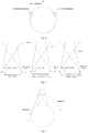
Fig. 2 is a schematic diagram of a cleaning robot provided with only a first obstacle detector according to an embodiment of the present disclosure; -
Fig. 3 is a schematic diagram of a cleaning robot provided with a first obstacle detector, a second obstacle detector and a third obstacle detector according to an embodiment of the present disclosure; -
Fig. 4 is a schematic diagram of a cleaning robot provided with only a second obstacle detector and a third obstacle detector according to an embodiment of the present disclosure; -
Fig. 5 is a schematic diagram illustrating a working principle of an obstacle detector according to an embodiment of the present disclosure; -
Fig. 6 is a schematic diagram illustrating a detection range of an obstacle detector according to an embodiment of the present disclosure; -
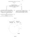
Fig. 7 is a flow chart of a distance detection method for a cleaning robot according to another embodiment of the present disclosure; -
Fig. 8 is a schematic diagram illustrating in-situ rotation of a cleaning robot when a first distance is reached according to an embodiment of the present disclosure; -
Fig. 9 is a block diagram of a distance detection device for a cleaning robot according to an embodiment of the present disclosure; -
Fig. 10 is a block diagram of a cleaning robot according to an embodiment of the present disclosure; and -
Fig. 11 is a block diagram of an electronic device according to an embodiment of the present disclosure. - Exemplary embodiments will be described in detail herein, and examples thereof are illustrated in accompanying drawings. Throughout figures referred by the following description, the same reference number in different figures indicates the same or similar elements. The embodiments described herein with reference to drawings are explanatory, and used to generally describe the present disclosure, which shall not be construed to limit the present disclosure.
- A distance detection method for a cleaning robot, a distance detection device for a cleaning robot, a cleaning robot, an electronic device and a non-transitory computer readable storage medium according to embodiments of the present disclosure are described below with reference to the drawings.
-
Fig. 1 is a flow chart of a distance detection method for a cleaning robot according to an embodiment of the present disclosure. As shown inFig. 1 , the method includes following steps. - In
block 101, detection data of an obstacle detector of the cleaning robot is acquired. - In the embodiments of the present disclosure, in order to prevent the cleaning robot from colliding with an obstacle and being damaged, the obstacle detector is disposed at the cleaning robot.
- According to a driving direction of the cleaning robot with respect to the obstacle, the cleaning robot may have a variety of obstacle detector arrangements as follows.
- Alternatively, when the moving direction of the cleaning robot is perpendicular to the contour line of the obstacle or a tangent line thereof, or an angle between the moving direction and the obstacle is an acute angle which is relatively large, in this case the obstacle detector disposed at the cleaning robot may include a first obstacle detector. As shown in
Fig. 2 , an obstacle detection function of the cleaning robot can be realized by the first obstacle detector disposed at the cleaning robot only. Specifically, the first obstacle detector is disposed at a forward end of the cleaning robot, and a scanning direction thereof is consistent with the moving direction of the cleaning robot. A detection range of the first obstacle detector is a certain area where the moving direction is regarded as a central axis of the area, and obstacles in this area can be detected. - It can be known from the above that the first obstacle detector can only detect a limited area in the moving direction of the cleaning robot. When the moving direction of the cleaning robot is not perpendicular to the obstacle surface or the acute angle between the moving direction of the cleaning robot and the obstacle is relatively small, the first obstacle detector disposed at the forward end of the cleaning robot cannot detect the obstacle before collision, or the first obstacle detector may detect the presence of the obstacle too late to stop the cleaning robot before the collision. Further, the obstacle detector disposed at the cleaning robot should include a second obstacle detector and a third obstacle detector which are symmetrically disposed at two sides of a body of the cleaning robot, as shown in
Fig. 3 . Obstacles in a detection blind zone of the first obstacle detector may be detected by the second obstacle detector and the third obstacle detector, which ensures that all the obstacles that may collide with the cleaning robot in the moving direction or at both sides of the moving direction can be detected during moving. - Alternatively, the obstacle detector disposed at the cleaning robot may include a second obstacle detector and a third obstacle detector only. Specifically, the second obstacle detector and the third obstacle detector are symmetrically disposed at two sides of a body of the cleaning robot, and an angle between each detector and the moving direction is in a range of 0 to α, where a is from 45° to 90°, as shown in
Fig. 4 . In the case where only the second obstacle detector and the third obstacle detector are provided, all the obstacles that may collide with the cleaning robot in the moving direction or at both sides of the moving direction can be detected during moving. - When the cleaning robot is in a working state, the obstacle detector of the cleaning robot also remains working to detect whether there is an obstacle that may collide with the cleaning robot. When the obstacle is detected, detection data for the obstacle is acquired.
- In an embodiment of the present disclosure, the obstacle detector includes a signal transmitting module and a signal receiving module which are arranged according to a preset angle and a preset distance. The signal transmitting module radiates a first signal outward, and the signal receiving module receives a second signal sent back from the obstacle after the first signal is transmitted to the obstacle.
Fig. 5 is a schematic diagram illustrating a working principle of an obstacle detector according to an embodiment of the present disclosure. As shown inFig. 5 , the signal transmitting module radiates a first signal outward, so as to form a first path between the signal transmitting module and the obstacle. The second signal forms a second path between the signal receiving module and the obstacle, and further convers into the detection data of the obstacle detector. InFig. 5 , a solid line refers to the first path formed by the first signal and a dotted line refers to the second path formed by the second signal. - In
block 102, it is determined according to the detection data whether a distance between the cleaning robot and an obstacle reaches a first distance, where the first distance is a distance between the cleaning robot and the obstacle at a moment when a changing trend of the detection data fits a preset changing trend. - In an embodiment of the present disclosure, the detection data includes the second signal reflected off the obstacle. After the detection data is acquired, the detection data is further analyzed, so as to identify a changing trend during the cleaning robot approaching the obstacle. In this embodiment, if the changing trend of the detection data fits a preset changing trend, the distance between the cleaning robot and the obstacle is determined as the first distance.
- With the distance detection method for a cleaning robot provided in the embodiments of the present disclosure, it is precisely detected whether the cleaning robot is moving to a specific positon a certain distance away from the obstacle. As the specific position is determined precisely, collision with obstacles can be avoided efficiently for the cleaning robot during working, and thus the distance detection method for the cleaning robot is improved.
- In the embodiments of the present disclosure, after the full detection in the moving direction of the cleaning robot is realized by different obstacle detector arrangements, the distance between the cleaning robot and the obstacle should be controlled to a certain degree according to the detection data. Specifically, a step of determining, according to the detection data, whether the distance between the cleaning robot and the obstacle reaches the first distance includes following steps.
- In block 201, the second signal is extracted from the detection data, the second signal detected in a period that the cleaning robot is moving is analyzed, and a changing trend of a signal intensity of the second signal is acquired.
- In block 202, it is determined whether the changing trend fits the preset changing trend.
- In block 203, a distance between the cleaning robot and the obstacle at a current moment is acquired if the changing trend is determined to fit the preset changing trend, where the distance at the current moment is the first distance.
- The detection data includes a second signal. After the second signal is extracted from the detection data, the signal intensity of the second signal is acquired according to reception time of the second signal. Then, the changing trend is identified to determine whether it fits the preset changing trend that the signal intensity is increased first and then decreased. If the identified changing trend fits the preset changing trend, according to the signal intensity at the current moment, a corresponding distance between the cleaning robot and the obstacle at the current moment is acquired.
- Specifically, the current moment is a moment when the signal intensity of the second signal is determined to be decreased. It is known from the above that when the signal intensity of the second signal is a maximum, the distance between the cleaning robot and the obstacle is the first distance, that is, the distance between the cleaning robot and the obstacle at the current moment is the first distance.
- Further, when it is determined that the changing trend of the second signal fits the preset changing trend, the distance between the cleaning robot and the obstacle at the current moment is acquired, such a step specifically includes: acquiring the distance between the cleaning robot and the obstacle at the current moment according to the signal intensity of the second signal at the current moment.
- Specifically, the signal intensity of the second signal has a one to one corresponding relationship with the distance between the cleaning robot and the obstacle (i.e., the first distance), that is, a different signal intensity of the second signal corresponds to a different distance value, and the distance value is the distance between the cleaning robot and the obstacle. The corresponding relationship is acquired by means of experimental acquisition during the development process of the cleaning robot. After an intensity of the second signal at the current moment is acquired, the distance between the cleaning robot and the obstacle can be acquired by querying the corresponding relationship.
- The above content is further explained with reference to
Fig. 5 . Angle and distance between the signal transmitting module and the signal receiving module in the figure can be preset such that the overlapping area between the two paths is increase first and then decreased. Specifically, during the process of the cleaning robot gradually approaching the obstacle from a distance, since the overlapping area between the first path and the second path is increased first and then decreased, that is, an area of the obstacle surface reflecting the first signal is first increased and then decreased as the cleaning robot approaches the obstacle, the signal intensity of the second signal is increased first and then decreased as the cleaning robot approaches the obstacle. Specifically, the larger the area of the obstacle surface reflecting the first signal is, the higher the intensity of the second signal generated by the reflection of the first signal is, otherwise, the lower the intensity of the second signal is. When the cleaning robot is at a certain distance from the obstacle, the overlapping area reaches a maximum and will start to be decrease as the cleaning robot further approaches. At this time, a maximum signal intensity of the second signal is acquired, and the certain distance is the first distance between the cleaning robot and the obstacle. - With the distance detection method for a cleaning robot provided in the embodiments of the present disclosure, it is precisely detected whether the cleaning robot is moving to a specific positon a certain distance away from the obstacle. As the specific position is determined precisely, collision with obstacles can be avoided efficiently for the cleaning robot during working, and thus the distance detection method for the cleaning robot is improved.
- In the embodiments of the present disclosure, different obstacle detector arrangements as described above may be selected in different conditions, and a specific selection principle is as follows.
- When the cleaning robot is moving in a direction perpendicular to the obstacle, the first obstacle detector is able to complete the corresponding detecting work.
- When the moving direction of the cleaning robot is not perpendicular to the obstacle, two situations may happen. In one situation, the acute angle between the moving direction of the cleaning robot and the obstacle is relatively large, as shown in
Fig. 6 , the obstacle is anobstacle 1 represented by the dotted line. During the cleaning robot approaching theobstacle 1, the overlapping area formed by the first signal and the second signal is increased first and then decreased. After the point A, the overlapping area becomes smaller, and the signal intensity of the second signal also becomes smaller, that is, the first distance is reached when the obstacle reaches the point A. At this time, the cleaning robot is close to the obstacle, but does not collide with the obstacle, and thus the cleaning robot can stop normally. In this case, the first obstacle detector is enough to complete the corresponding detecting work. In another situation, the acute angle between the moving direction of the cleaning robot and the obstacle is relatively small, as shown inFig. 6 , the obstacle is anobstacle 2 represented by the solid line. As the cleaning robot approaches the obstacle, the overlapping area is increased. However, before the obstacle passes the point A, the cleaning robot may have collided with the obstacle. In this case the first obstacle detector cannot realize the distance control of the obstacle at that angle. Therefore, the second obstacle detector and the third obstacle detector are required to be disposed at the two sides of the cleaning robot. - Alternatively, in the case that the first obstacle detector is unable to perform the detection, a minimum of the signal intensity of the second signal may be set to realize a switch from the first obstacle detector being working to the second and third obstacle detectors being working. As shown in
Fig. 6 , a signal intensity of the second signal corresponding to a case where the obstacle passes the point A and is tangential to the cleaning robot is a minimum signal intensity threshold that the cleaning robot is able to stop by itself. When the signal intensity of the second signal is detected to be decreased to such a threshold, the first obstacle detector stops working immediately, and the second obstacle detector and the third obstacle detector are turned on. Specifically, a detector that has not received any obstacle information within a certain period is turned off, and another detector may continuously detect the obstacle. - Alternatively, the obstacle detector may be switched to continue the detection without determining whether the first obstacle detector is feasible or not. All obstacle detectors may be turned on. If an acute angle between the detection axis of an obstacle detector and the obstacle is closer to 0°, the first distance will be reached sooner for such an obstacle detector, and the signal intensity of the second signal will be higher when the first distance is reached. According to this principle, considering the changing trends of the signal intensities of the second signals collected by all obstacle detectors, when any of the signal intensities starts to decrease, the cleaning robot stops moving, so that the current first distance of the cleaning robot is as close as possible to an optimal distance of the cleaning robot from the obstacle. Specifically, the optimal distance is the first distance when the moving direction of the cleaning robot is perpendicular to the obstacle. At such a first distance, the cleaning robot stops at the farthest distance from the obstacle, thus efficiently prevent the cleaning robot from colliding with the obstacle.
- Further, when only the second obstacle detector and the third obstacle detector are located at the two sides of the body of the cleaning robot, the two obstacle detectors may be activated once at a preset time interval, where a product of the time length of the interval and a speed of the cleaning robot is less than a distance from detection of the obstacle to the collision with the obstacle in any case, so as to detect whether there is an obstacle in front. As shown in
Fig. 5 , the overlapping of the paths may be decreased or even disappear as the distance between the cleaning robot and the obstacle is increased, such that the obstacle detector has a limited detection direction. If no obstacle is detected within the detection distance, the obstacle detector will be turned off again and wait for the preset time interval to restart the detection. When an obstacle is detected in the detection range, the obstacle detector remains working for continuous detection until the cleaning robot reaches the first distance from the obstacle and then be turned off. - Specifically, when both the second obstacle detector and the third obstacle detector detect an obstacle, the changing trends of the signal intensities of the second signals of both detectors are acquired. If any of the signal intensities starts to decrease, it is determined that the cleaning robot arrives at the first distance from the obstacle and stops moving. Specifically, when the signal intensities of the second signals of the two detectors are the same, it is determined that the obstacle is perpendicular to the moving direction of the cleaning robot.
- During the cleaning robot approaching the obstacle, the obstacle detector can detect the distance between the cleaning robot and the obstacle in real time, to enable the cleaning root to stop once reaching the first distance. After this, the cleaning robot needs to change its moving direction to continue to work to avoid collision with the obstacle.
Fig. 7 is a flow chart of a distance detection method for a cleaning robot according to another embodiment of the present disclosure. As shown inFig. 7 , in order to solve the above problem, the following steps are specifically included. - In
block 301, when the distance between the cleaning robot and the obstacle does not reach the first distance, the cleaning robot is controlled to continue to advance and it is returned to perform the step of acquiring the detection data and subsequent steps. - Specifically, when the distance between the cleaning robot and the obstacle does not reach the first distance, that is, the signal intensity of the second signal has not yet reached a decreased point, the cleaning robot is controlled to continue to advance. Moreover, steps of acquiring detection data of an obstacle detector of the cleaning robot, and determining, according to the detection data, whether the distance between the cleaning robot and the obstacle reaches the first distance as described above are repeated until it is determined that the distance between the cleaning robot and the obstacle reaches the first distance.
- In
block 302, when the distance between the cleaning robot and the obstacle reaches the first distance, the cleaning robot is controlled to rotate in situ, such that a moving direction of the cleaning robot is parallel to a contour line of the obstacle or a tangent line of a contour line of the obstacle. - In
block 303, the cleaning robot is controlled to move in the moving direction, and the distance between the cleaning robot and the obstacle during the moving is controlled to be maintained within a preset distance range. - Specifically, the steps of acquiring detection data of an obstacle detector of the cleaning robot, and determining, according to the detection data, whether the distance between the cleaning robot and the obstacle reaches the first distance as described above are repeated. When it is determined that the distance between the cleaning robot and the obstacle reaches the first distance, the cleaning robot is controlled to stop, and it is determined according to identifier information of an obstacle detector of the detection data whether the cleaning robot should rotate clockwise or counterclockwise in situ. Specifically, a way to decide a rotation direction of the cleaning robot in situ according to the identifier information of the obstacle detector will be described in detail below and thus is not described here. Meanwhile, as shown in
Fig. 8 , the cleaning robot is controlled to rotate, in a corresponding clockwise or counterclockwise direction, an angular displacement of an acute angle between the moving direction of the cleaning robot and the obstacle. As shown inFig. 8 , the moving direction after the rotation of the cleaning robot is parallel to the contour line of the obstacle or the tangent line thereof, so that the cleaning robot may continue to move along the direction parallel to the contour line of the obstacle or the tangent line thereof. Moreover, a distance sensor may be disposed at the two sides of the cleaning robot to monitor the distance between the cleaning robot and the obstacle during moving in real time, so that the distance between the cleaning robot and the obstacle during the moving is maintained within the preset distance range. - Further, when the moving direction the cleaning robot is perpendicular to the obstacle, it is difficult to determine whether the cleaning robot rotates in situ clockwise or counterclockwise. In this case, the rotation direction may be randomly selected, or the obstacle detectors on both sides of the body of the cleaning robot may be used to detect the surroundings so as to enable the cleaning robot to rotate to a side with fewer obstacles preferentially, thus preventing the cleaning robot from collision with the obstacles and reducing times of adjustments of the moving direction of the cleaning robot during cleaning process.
- In an embodiment of the present disclosure, the detection data further includes identifier information of an obstacle detector. By extracting the identifier information of the detector from the detection data, a general direction of an obstacle related to the obstacle detector may be determined as follows.
- The identifier information of the detector is extracted from the detection data, and a target obstacle detector to which the detection data belongs is identified according to the identifier information.
- Further, a relative positional relationship between the cleaning robot and the obstacle is determined according to a position where the target obstacle detector is disposed at the cleaning robot.
- Specifically, the identifier information of the obstacle detector is extracted from the detection data, and the position where the obstacle detector is located is also considered. For example, when the detection data includes the identifier information of the second obstacle detector but does not include the identifier information of the third obstacle detector, it indicates that the current detection data is acquired by the second obstacle detector. For example, as shown in
Fig. 4 , the second obstacle detector is disposed at a front-left side of the cleaning robot, the cleaning robot thus can determine that the obstacle is in front-left of the cleaning robot. Moreover, when the claning root reaches the first distance from the obstacle, it stops and rotates clockwise in situ, such that the cleaning robot may rotate a minimum angle to make the moving direction of the cleaning robot in consistency with the contour of the obstacle or the tangent line thereof. - In order to realize the above embodiments, the present disclosure provides a distance detection device for a cleaning robot.
Fig. 9 is a block diagram of a distance detection device for a cleaning robot according to an embodiment of the present disclosure. Specifically, anobstacle detector 91 and thedistance detection device 92 are disposed at the cleaning robot. Theobstacle detector 91 is configured to detect an obstacle, and theobstacle detector 91 is connected to thedistance detection device 92. - Specifically, the
distance detection device 92 includes: a detectiondata acquiring module 921 configured to acquire detection data of the obstacle detector of the cleaning robot, and a determiningmodule 922 configured to determine, according to the detection data, whether a distance between the cleaning robot and an obstacle reaches a first distance, where the first distance is a distance between the cleaning robot and the obstacle at a moment when a changing trend of the detection data fits in a preset changing trend. - Specifically, each
obstacle detector 91 includes a signal transmitting module and a signal receiving module, where the signal transmitting module and the signal receiving module are arranged according to preset angle and a preset distance, such that an overlapping area exists between a first path and a second path, the first path being formed between the signal transmitting module and the obstacle and the second path being formed between the signal receiving module and the obstacle, and the overlapping area reaches a maximum when the distance between the cleaning robot and the obstacle reaches the first distance. - In some embodiments, the
obstacle detector 91 includes a first obstacle detector disposed at a forward end of the cleaning robot. - In other embodiments, the
obstacle detector 91 further includes a second obstacle detector and a third obstacle detector, and the second obstacle detector and the third obstacle detector are symmetrically disposed at two sides of a body of the cleaning robot. - Alternatively, the obstacle detector includes a second obstacle detector and a third obstacle detector, and the second obstacle detector and the third obstacle detector are symmetrically disposed at two sides of a body of the cleaning robot.
- Specifically, the signal transmitting module included in the
obstacle detector 91 is configured to radiate first signal outward, and the corresponding signal receiving module is configured to receive second signal sent back from the obstacle which the first signal is transmitted to the obstacle. The detection data includes the second signal. - The determining
module 922 is specifically configured to: - extract the second signal from the detection data, analyze the second signal detected in a period that the cleaning robot is moving, and acquire a changing trend of a signal intensity of the second signal,
- determine whether the changing trend is the preset changing trend, and
- acquire a distance between the cleaning robot and the obstacle at a current moment if the changing trend is determined as the preset changing trend, where the distance at the current moment is the first distance.
- As the preset changing trend is that a signal intensity is increased first and then decreased, the determining
module 922 is further configured to:
acquire the distance between the cleaning robot and the obstacle according to the signal intensity of the second signal at the current moment, where the current moment is a moment when the signal intensity of the second signal is determined to be decreased. - Further, the
distance detection device 92 includes: a controllingmodule 923 connected to the determiningmodule 922 and the detectiondata acquiring module 921. - Specifically, when the distance between the cleaning robot and the obstacle does not reach the first distance, the controlling
module 923 is configured to control the cleaning robot to continue to advance and return to perform the process of acquiring the detection data and subsequent processes. - When the distance between the cleaning robot and the obstacle reaches the first distance, the controlling module is configured to control the cleaning robot to rotate in situ, such that a moving direction of the cleaning robot is parallel to a boundary line of the obstacle or a tangent line of a boundary line of the obstacle, and control the cleaning robot to move in the moving direction.
- Further, the controlling
module 923 is further configured to: - extract identifier information of an obstacle detector from the detection data, and identify, according to the identifier information, a target obstacle detector to which the detection data belongs, and
- determine a relative positional relationship between the cleaning robot and the obstacle according to a position where the target obstacle detector is disposed at the cleaning robot.
- In order to realize the above embodiments, the present disclosure provides a cleaning robot.
Fig. 10 is a block diagram of a cleaning robot according to an embodiment of the present disclosure. As shown inFig. 10 , anobstacle detector 91, adistance detection device 92 as described above and acleaning control device 93 are disposed at the cleaning robot. Thedistance detection device 92 is connected to thecleaning control device 93. - Specifically, the
obstacle detector 91 is configured to detect an obstacle, and thecleaning control device 93 is configured to perform a cleaning operation. - In order to realize the above embodiments, the present disclosure provides an electronic device.
Fig. 11 is a block diagram of an electronic device according to an embodiment of the present disclosure. As shown inFig. 11 , the electronic device includes aprocessor 111 and amemory 112. - Specifically, the
processor 112 reads an executable program code stored in thememory 111 to execute a program corresponding to the executable program code, so as to perform a distance detection method for a cleaning robot as described in the above embodiments of the present disclosure. - In order to realize the above embodiments, the present disclosure provides a non-transitory computer readable storage medium having stored therein a computer program that, when executed by a processor, causes the processor to perform a distance detection method for a cleaning robot as described in the above embodiments of the present disclosure.
- In the specification, it is to be understood that terms such as "central", "longitudinal", "lateral", "length", "width", "thickness", "upper", "lower", "front", "rear", "left", "right", "vertical", "horizontal", "top", "bottom", "inner", "outer", "clockwise", "counterclockwise", "axial", "radial" and "circumferential" should be construed to refer to the orientation as then described or as shown in the drawings under discussion. These relative terms are for convenience of description and do not require that the present disclosure be constructed or operated in a particular orientation, and thus shall not be construed to limit the present disclosure.
- In addition, terms such as "first" and "second" are used herein for purposes of description and are not intended to indicate or imply relative importance or significance or to imply the number of indicated technical features. Thus, the feature defined with "first" and "second" may include one or more of this feature. In the description of the present disclosure, unless specified otherwise, "a plurality of' means two or more than two.
- In the present disclosure, unless specified or limited otherwise, the terms "mounted", "connected", "coupled", "fixed" and the like are used broadly, and may be, for example, fixed connections, detachable connections, or integral connections; may also be mechanical or electrical connections; may also be direct connections or indirect connections via intervening structures; may also be inner communications of two elements, which can be understood by those skilled in the art according to specific situations.
- In the description, unless specified or limited otherwise, a structure in which a first feature is "on" or "below" a second feature may include an embodiment in which the first feature is in direct contact with the second feature, and may also include an embodiment in which the first feature and the second feature are not in direct contact with each other, but are contacted via an additional feature formed therebetween. Furthermore, a first feature "on", "above" or "on top of' a second feature may include an embodiment in which the first feature is right or obliquely "on", "above" or "on top of' the second feature, or just means that the first feature is at a height higher than that of the second feature; while a first feature "below", "under" or "on bottom of' a second feature may include an embodiment in which the first feature is right or obliquely "below", "under" or "on bottom of' the second feature, or just means that the first feature is at a height lower than that of the second feature.
- Reference throughout this specification to "an embodiment", "some embodiments", "an example", "a specific example", or "some examples" means that a particular feature, structure, material, or characteristic described in connection with the embodiment or example is included in at least one embodiment or example of the present disclosure. Thus, the appearances of above phrases in various places throughout this specification are not necessarily referring to the same embodiment or example of the present disclosure. Furthermore, the particular features, structures, materials, or characteristics may be combined in any suitable manner in one or more embodiments or examples. In addition, different embodiments or examples described in the specification, as well as features of embodiments or examples, without conflicting, may be combined by one skilled in the art.
- Although explanatory embodiments have been shown and described, it would be appreciated by those skilled in the art that the above embodiments cannot be construed to limit the present disclosure, and changes, alternatives, and modifications can be made in the embodiments without departing from spirit, principles and scope of the present disclosure.
Claims (14)
determining (102), according to the detection data, whether the distance between the cleaning robot and the obstacle reaches the first distance comprises:
the distance detection device comprises:
the determining module (922) is specifically configured to:
wherein the obstacle detector (91) is configured to detect an obstacle, and the cleaning device is configured to perform a cleaning operation.
Applications Claiming Priority (1)
| Application Number | Priority Date | Filing Date | Title |
|---|---|---|---|
| CN201811495536.XA CN109407670B (en) | 2018-12-07 | 2018-12-07 | Distance detection method and device of sweeping robot and sweeping robot |
Publications (2)
| Publication Number | Publication Date |
|---|---|
| EP3663795A1 true EP3663795A1 (en) | 2020-06-10 |
| EP3663795B1 EP3663795B1 (en) | 2024-02-21 |
Family
ID=65457822
Family Applications (1)
| Application Number | Title | Priority Date | Filing Date |
|---|---|---|---|
| EP19214006.9A Active EP3663795B1 (en) | 2018-12-07 | 2019-12-06 | Distance detection method and device for cleaning robot, and cleaning robot |
Country Status (3)
| Country | Link |
|---|---|
| US (1) | US11474526B2 (en) |
| EP (1) | EP3663795B1 (en) |
| CN (1) | CN109407670B (en) |
Cited By (1)
| Publication number | Priority date | Publication date | Assignee | Title |
|---|---|---|---|---|
| CN116138653A (en) * | 2021-11-22 | 2023-05-23 | 追觅创新科技(苏州)有限公司 | Cleaning equipment operation control method and device, storage medium and electronic device |
Families Citing this family (13)
| Publication number | Priority date | Publication date | Assignee | Title |
|---|---|---|---|---|
| CN111766607A (en) * | 2019-03-13 | 2020-10-13 | 科沃斯机器人股份有限公司 | Self-moving equipment and non-contact obstacle detection device |
| CN110244743B (en) * | 2019-07-03 | 2022-02-01 | 浙江大学 | Mobile robot autonomous escaping method fusing multi-sensor information |
| CN110597260A (en) * | 2019-09-20 | 2019-12-20 | 深圳乐动机器人有限公司 | Robot obstacle avoidance method and robot |
| CN110989621B (en) * | 2019-12-20 | 2025-05-20 | 深圳市杉川机器人有限公司 | Control method of autonomous robot and autonomous robot |
| CN116069033B (en) * | 2020-05-15 | 2026-01-02 | 科沃斯机器人股份有限公司 | Information collection methods, equipment and storage media |
| CN114451814B (en) * | 2020-11-10 | 2023-12-08 | 苏州宝时得电动工具有限公司 | Automatic walking equipment and control method of automatic walking equipment |
| CN112486184B (en) * | 2020-12-10 | 2023-08-11 | 北京小狗吸尘器集团股份有限公司 | Sweeping robot and obstacle avoidance path determining method thereof |
| CN112528959B (en) * | 2020-12-29 | 2024-06-07 | 上海同温层信息科技有限公司 | Obstacle recognition method for cleaning robot |
| EP4059403B8 (en) * | 2021-01-19 | 2023-12-27 | Yituo Electric Co., Ltd. | Control method and control device of cleaning equipment |
| CN115191868B (en) * | 2021-04-09 | 2024-06-14 | 美智纵横科技有限责任公司 | Edge cleaning method and cleaning robot |
| WO2023042500A1 (en) * | 2021-09-15 | 2023-03-23 | 日本電産株式会社 | Autonomous traveling device and autonomous traveling device control method |
| CN115562309A (en) * | 2022-11-03 | 2023-01-03 | 上海高仙自动化科技发展有限公司 | Robot meeting method, controller, storage medium and robot |
| CN119138802B (en) * | 2023-06-12 | 2025-10-03 | 珠海一微半导体股份有限公司 | Collision prediction method for non-circular cleaning robots |
Citations (4)
| Publication number | Priority date | Publication date | Assignee | Title |
|---|---|---|---|---|
| US20050251292A1 (en) * | 2000-01-24 | 2005-11-10 | Irobot Corporation | Obstacle following sensor scheme for a mobile robot |
| US20120065829A1 (en) * | 2010-09-15 | 2012-03-15 | Jyh-Cheng Yu | Wall-following Moving Device |
| CN109464075A (en) * | 2018-12-07 | 2019-03-15 | 江苏美的清洁电器股份有限公司 | Cleaning control method and device for sweeping robot and sweeping robot |
| CN109567678A (en) * | 2018-12-07 | 2019-04-05 | 江苏美的清洁电器股份有限公司 | The cleaning control method and its device and sweeping robot of sweeping robot |
Family Cites Families (19)
| Publication number | Priority date | Publication date | Assignee | Title |
|---|---|---|---|---|
| GB582708A (en) * | 1942-04-03 | 1946-11-26 | Standard Telephones Cables Ltd | Improvements in arrangements for obstacle detection and measurement of distances by electromagnetic waves |
| KR100633444B1 (en) * | 2005-02-24 | 2006-10-13 | 삼성광주전자 주식회사 | Robot cleaner and its control method |
| KR100692897B1 (en) * | 2005-10-28 | 2007-03-12 | 엘지전자 주식회사 | Mobile robot |
| JP2010099366A (en) * | 2008-10-27 | 2010-05-06 | Panasonic Corp | Self-propelled cleaner |
| US9020641B2 (en) * | 2012-06-07 | 2015-04-28 | Samsung Electronics Co., Ltd. | Obstacle sensing module and cleaning robot including the same |
| CN104007765B (en) * | 2014-06-16 | 2016-05-04 | 成都北斗群星智能科技有限公司 | Sweeping robot is kept away barrier, localization method |
| JP6453583B2 (en) * | 2014-08-20 | 2019-01-16 | 東芝ライフスタイル株式会社 | Electric vacuum cleaner |
| EP3186657B1 (en) * | 2014-10-31 | 2021-04-14 | Siemens Schweiz AG | Method, digital tool, device and system for detecting movements of objects and/or living beings in a radio range, in particular of an indoor area |
| CN104765363B (en) * | 2014-12-10 | 2018-04-24 | 深圳市银星智能科技股份有限公司 | Intelligent robot for sweeping floor and its control method |
| CN105223951B (en) * | 2015-09-14 | 2018-01-26 | 苏州爱普电器有限公司 | Self-movement robot |
| CN105955304B (en) * | 2016-07-06 | 2024-11-08 | 零度智控(北京)智能科技有限公司 | Obstacle avoidance method, obstacle avoidance device and unmanned aerial vehicle |
| JP6931994B2 (en) * | 2016-12-22 | 2021-09-08 | パナソニック インテレクチュアル プロパティ コーポレーション オブ アメリカPanasonic Intellectual Property Corporation of America | Autonomous mobile body, mobile control method and mobile control program |
| CN106725127B (en) * | 2017-02-04 | 2020-06-02 | 北京小米移动软件有限公司 | Sweeping method and device of sweeping robot |
| TW201833701A (en) * | 2017-03-14 | 2018-09-16 | 聯潤科技股份有限公司 | Self-propelling cleansing device and method thereof for establishing indoor map comprising a device body driving by wheels at a bottom thereof, a distance detection unit, an along-edge detector, a cleansing unit, a dust collection unit, a dynamic detection unit, a map establishing unit, and a control unit |
| CN106821157A (en) * | 2017-04-14 | 2017-06-13 | 小狗电器互联网科技(北京)股份有限公司 | The cleaning method that a kind of sweeping robot is swept the floor |
| JP7007108B2 (en) * | 2017-05-23 | 2022-01-24 | 東芝ライフスタイル株式会社 | Vacuum cleaner |
| CN107450569A (en) * | 2017-09-27 | 2017-12-08 | 上海思岚科技有限公司 | The control method and equipment of a kind of sweeping robot |
| CN107831766A (en) * | 2017-10-30 | 2018-03-23 | 北京奇虎科技有限公司 | Collision processing method, device and the robot of robot |
| CN107775640B (en) * | 2017-12-05 | 2024-06-18 | 深圳银星智能集团股份有限公司 | move robot |
-
2018
- 2018-12-07 CN CN201811495536.XA patent/CN109407670B/en active Active
-
2019
- 2019-12-03 US US16/701,158 patent/US11474526B2/en active Active
- 2019-12-06 EP EP19214006.9A patent/EP3663795B1/en active Active
Patent Citations (4)
| Publication number | Priority date | Publication date | Assignee | Title |
|---|---|---|---|---|
| US20050251292A1 (en) * | 2000-01-24 | 2005-11-10 | Irobot Corporation | Obstacle following sensor scheme for a mobile robot |
| US20120065829A1 (en) * | 2010-09-15 | 2012-03-15 | Jyh-Cheng Yu | Wall-following Moving Device |
| CN109464075A (en) * | 2018-12-07 | 2019-03-15 | 江苏美的清洁电器股份有限公司 | Cleaning control method and device for sweeping robot and sweeping robot |
| CN109567678A (en) * | 2018-12-07 | 2019-04-05 | 江苏美的清洁电器股份有限公司 | The cleaning control method and its device and sweeping robot of sweeping robot |
Cited By (1)
| Publication number | Priority date | Publication date | Assignee | Title |
|---|---|---|---|---|
| CN116138653A (en) * | 2021-11-22 | 2023-05-23 | 追觅创新科技(苏州)有限公司 | Cleaning equipment operation control method and device, storage medium and electronic device |
Also Published As
| Publication number | Publication date |
|---|---|
| CN109407670B (en) | 2022-03-04 |
| CN109407670A (en) | 2019-03-01 |
| US11474526B2 (en) | 2022-10-18 |
| EP3663795B1 (en) | 2024-02-21 |
| US20200183404A1 (en) | 2020-06-11 |
Similar Documents
| Publication | Publication Date | Title |
|---|---|---|
| EP3663795B1 (en) | Distance detection method and device for cleaning robot, and cleaning robot | |
| US20200178750A1 (en) | Cleaning control method and device for cleaning robot, and cleaning robot | |
| US11635766B2 (en) | Method for docking and automatically charging robot, charging station and robot | |
| CN109567678B (en) | Sweeping control method and device of sweeping robot and sweeping robot | |
| JP5929870B2 (en) | Target detection device | |
| US10446034B2 (en) | Driving support system | |
| JP6285303B2 (en) | Vehicle control device | |
| US10668919B2 (en) | Object detection apparatus and object detection method | |
| JP6597408B2 (en) | Collision mitigation control device | |
| KR20220066388A (en) | Radar sensor system and method for non-contact movement of vehicle door relative to body | |
| US11091153B2 (en) | Vehicle control apparatus and vehicle control method | |
| WO2016158989A1 (en) | Vehicle control device and vehicle control method | |
| WO2015097511A1 (en) | Vehicle surrounding situation estimation device | |
| US11293211B2 (en) | Vehicle door opening and closing device | |
| JP2016080639A (en) | Object detection device, vehicle control device | |
| US20210053555A1 (en) | Remote parking device and remote parking method | |
| CN115027456A (en) | Vehicle control method, system and storage medium | |
| CN106980316B (en) | A kind of ultrasonic array obstacle avoidance system applied to mobile platform | |
| CN113341417A (en) | Detection radar-based road obstacle detection method, vehicle and storage medium | |
| JP2017159801A (en) | Self-driving control device and self-driving system | |
| KR20180069019A (en) | A method for capturing a peripheral area of an automobile by object classification, a control device, a driver assistance system, and an automobile | |
| CN110596708A (en) | Vehicle distance detection method and device, vehicle and storage medium | |
| JP2005326296A (en) | Vehicle object detection device | |
| JP4745151B2 (en) | Mobile robot | |
| CN118884952A (en) | Obstacle avoidance method and related device for mobile equipment |
Legal Events
| Date | Code | Title | Description |
|---|---|---|---|
| PUAI | Public reference made under article 153(3) epc to a published international application that has entered the european phase |
Free format text: ORIGINAL CODE: 0009012 |
|
| STAA | Information on the status of an ep patent application or granted ep patent |
Free format text: STATUS: THE APPLICATION HAS BEEN PUBLISHED |
|
| AK | Designated contracting states |
Kind code of ref document: A1 Designated state(s): AL AT BE BG CH CY CZ DE DK EE ES FI FR GB GR HR HU IE IS IT LI LT LU LV MC MK MT NL NO PL PT RO RS SE SI SK SM TR |
|
| AX | Request for extension of the european patent |
Extension state: BA ME |
|
| STAA | Information on the status of an ep patent application or granted ep patent |
Free format text: STATUS: REQUEST FOR EXAMINATION WAS MADE |
|
| 17P | Request for examination filed |
Effective date: 20201027 |
|
| RBV | Designated contracting states (corrected) |
Designated state(s): AL AT BE BG CH CY CZ DE DK EE ES FI FR GB GR HR HU IE IS IT LI LT LU LV MC MK MT NL NO PL PT RO RS SE SI SK SM TR |
|
| RAP1 | Party data changed (applicant data changed or rights of an application transferred) |
Owner name: MIDEA ROBOZONE TECHNOLOGY CO., LTD. |
|
| STAA | Information on the status of an ep patent application or granted ep patent |
Free format text: STATUS: EXAMINATION IS IN PROGRESS |
|
| 17Q | First examination report despatched |
Effective date: 20220503 |
|
| GRAP | Despatch of communication of intention to grant a patent |
Free format text: ORIGINAL CODE: EPIDOSNIGR1 |
|
| STAA | Information on the status of an ep patent application or granted ep patent |
Free format text: STATUS: GRANT OF PATENT IS INTENDED |
|
| INTG | Intention to grant announced |
Effective date: 20231102 |
|
| GRAS | Grant fee paid |
Free format text: ORIGINAL CODE: EPIDOSNIGR3 |
|
| GRAA | (expected) grant |
Free format text: ORIGINAL CODE: 0009210 |
|
| STAA | Information on the status of an ep patent application or granted ep patent |
Free format text: STATUS: THE PATENT HAS BEEN GRANTED |
|
| AK | Designated contracting states |
Kind code of ref document: B1 Designated state(s): AL AT BE BG CH CY CZ DE DK EE ES FI FR GB GR HR HU IE IS IT LI LT LU LV MC MK MT NL NO PL PT RO RS SE SI SK SM TR |
|
| REG | Reference to a national code |
Ref country code: GB Ref legal event code: FG4D |
|
| REG | Reference to a national code |
Ref country code: CH Ref legal event code: EP |
|
| REG | Reference to a national code |
Ref country code: DE Ref legal event code: R096 Ref document number: 602019046846 Country of ref document: DE |
|
| REG | Reference to a national code |
Ref country code: IE Ref legal event code: FG4D |
|
| REG | Reference to a national code |
Ref country code: LT Ref legal event code: MG9D |
|
| P01 | Opt-out of the competence of the unified patent court (upc) registered |
Effective date: 20240520 |
|
| REG | Reference to a national code |
Ref country code: NL Ref legal event code: MP Effective date: 20240221 |
|
| PG25 | Lapsed in a contracting state [announced via postgrant information from national office to epo] |
Ref country code: IS Free format text: LAPSE BECAUSE OF FAILURE TO SUBMIT A TRANSLATION OF THE DESCRIPTION OR TO PAY THE FEE WITHIN THE PRESCRIBED TIME-LIMIT Effective date: 20240621 |
|
| PG25 | Lapsed in a contracting state [announced via postgrant information from national office to epo] |
Ref country code: LT Free format text: LAPSE BECAUSE OF FAILURE TO SUBMIT A TRANSLATION OF THE DESCRIPTION OR TO PAY THE FEE WITHIN THE PRESCRIBED TIME-LIMIT Effective date: 20240221 |
|
| PG25 | Lapsed in a contracting state [announced via postgrant information from national office to epo] |
Ref country code: GR Free format text: LAPSE BECAUSE OF FAILURE TO SUBMIT A TRANSLATION OF THE DESCRIPTION OR TO PAY THE FEE WITHIN THE PRESCRIBED TIME-LIMIT Effective date: 20240522 |
|
| REG | Reference to a national code |
Ref country code: AT Ref legal event code: MK05 Ref document number: 1659562 Country of ref document: AT Kind code of ref document: T Effective date: 20240221 |
|
| PG25 | Lapsed in a contracting state [announced via postgrant information from national office to epo] |
Ref country code: RS Free format text: LAPSE BECAUSE OF FAILURE TO SUBMIT A TRANSLATION OF THE DESCRIPTION OR TO PAY THE FEE WITHIN THE PRESCRIBED TIME-LIMIT Effective date: 20240521 Ref country code: NL Free format text: LAPSE BECAUSE OF FAILURE TO SUBMIT A TRANSLATION OF THE DESCRIPTION OR TO PAY THE FEE WITHIN THE PRESCRIBED TIME-LIMIT Effective date: 20240221 Ref country code: HR Free format text: LAPSE BECAUSE OF FAILURE TO SUBMIT A TRANSLATION OF THE DESCRIPTION OR TO PAY THE FEE WITHIN THE PRESCRIBED TIME-LIMIT Effective date: 20240221 |
|
| PG25 | Lapsed in a contracting state [announced via postgrant information from national office to epo] |
Ref country code: ES Free format text: LAPSE BECAUSE OF FAILURE TO SUBMIT A TRANSLATION OF THE DESCRIPTION OR TO PAY THE FEE WITHIN THE PRESCRIBED TIME-LIMIT Effective date: 20240221 |
|
| PG25 | Lapsed in a contracting state [announced via postgrant information from national office to epo] |
Ref country code: AT Free format text: LAPSE BECAUSE OF FAILURE TO SUBMIT A TRANSLATION OF THE DESCRIPTION OR TO PAY THE FEE WITHIN THE PRESCRIBED TIME-LIMIT Effective date: 20240221 |
|
| PG25 | Lapsed in a contracting state [announced via postgrant information from national office to epo] |
Ref country code: RS Free format text: LAPSE BECAUSE OF FAILURE TO SUBMIT A TRANSLATION OF THE DESCRIPTION OR TO PAY THE FEE WITHIN THE PRESCRIBED TIME-LIMIT Effective date: 20240521 Ref country code: NO Free format text: LAPSE BECAUSE OF FAILURE TO SUBMIT A TRANSLATION OF THE DESCRIPTION OR TO PAY THE FEE WITHIN THE PRESCRIBED TIME-LIMIT Effective date: 20240521 Ref country code: NL Free format text: LAPSE BECAUSE OF FAILURE TO SUBMIT A TRANSLATION OF THE DESCRIPTION OR TO PAY THE FEE WITHIN THE PRESCRIBED TIME-LIMIT Effective date: 20240221 Ref country code: LT Free format text: LAPSE BECAUSE OF FAILURE TO SUBMIT A TRANSLATION OF THE DESCRIPTION OR TO PAY THE FEE WITHIN THE PRESCRIBED TIME-LIMIT Effective date: 20240221 Ref country code: IS Free format text: LAPSE BECAUSE OF FAILURE TO SUBMIT A TRANSLATION OF THE DESCRIPTION OR TO PAY THE FEE WITHIN THE PRESCRIBED TIME-LIMIT Effective date: 20240621 Ref country code: HR Free format text: LAPSE BECAUSE OF FAILURE TO SUBMIT A TRANSLATION OF THE DESCRIPTION OR TO PAY THE FEE WITHIN THE PRESCRIBED TIME-LIMIT Effective date: 20240221 Ref country code: GR Free format text: LAPSE BECAUSE OF FAILURE TO SUBMIT A TRANSLATION OF THE DESCRIPTION OR TO PAY THE FEE WITHIN THE PRESCRIBED TIME-LIMIT Effective date: 20240522 Ref country code: FI Free format text: LAPSE BECAUSE OF FAILURE TO SUBMIT A TRANSLATION OF THE DESCRIPTION OR TO PAY THE FEE WITHIN THE PRESCRIBED TIME-LIMIT Effective date: 20240221 Ref country code: ES Free format text: LAPSE BECAUSE OF FAILURE TO SUBMIT A TRANSLATION OF THE DESCRIPTION OR TO PAY THE FEE WITHIN THE PRESCRIBED TIME-LIMIT Effective date: 20240221 Ref country code: BG Free format text: LAPSE BECAUSE OF FAILURE TO SUBMIT A TRANSLATION OF THE DESCRIPTION OR TO PAY THE FEE WITHIN THE PRESCRIBED TIME-LIMIT Effective date: 20240221 Ref country code: AT Free format text: LAPSE BECAUSE OF FAILURE TO SUBMIT A TRANSLATION OF THE DESCRIPTION OR TO PAY THE FEE WITHIN THE PRESCRIBED TIME-LIMIT Effective date: 20240221 |
|
| PG25 | Lapsed in a contracting state [announced via postgrant information from national office to epo] |
Ref country code: PL Free format text: LAPSE BECAUSE OF FAILURE TO SUBMIT A TRANSLATION OF THE DESCRIPTION OR TO PAY THE FEE WITHIN THE PRESCRIBED TIME-LIMIT Effective date: 20240221 Ref country code: PT Free format text: LAPSE BECAUSE OF FAILURE TO SUBMIT A TRANSLATION OF THE DESCRIPTION OR TO PAY THE FEE WITHIN THE PRESCRIBED TIME-LIMIT Effective date: 20240621 |
|
| PG25 | Lapsed in a contracting state [announced via postgrant information from national office to epo] |
Ref country code: SE Free format text: LAPSE BECAUSE OF FAILURE TO SUBMIT A TRANSLATION OF THE DESCRIPTION OR TO PAY THE FEE WITHIN THE PRESCRIBED TIME-LIMIT Effective date: 20240221 Ref country code: PT Free format text: LAPSE BECAUSE OF FAILURE TO SUBMIT A TRANSLATION OF THE DESCRIPTION OR TO PAY THE FEE WITHIN THE PRESCRIBED TIME-LIMIT Effective date: 20240621 Ref country code: PL Free format text: LAPSE BECAUSE OF FAILURE TO SUBMIT A TRANSLATION OF THE DESCRIPTION OR TO PAY THE FEE WITHIN THE PRESCRIBED TIME-LIMIT Effective date: 20240221 Ref country code: LV Free format text: LAPSE BECAUSE OF FAILURE TO SUBMIT A TRANSLATION OF THE DESCRIPTION OR TO PAY THE FEE WITHIN THE PRESCRIBED TIME-LIMIT Effective date: 20240221 |
|
| PG25 | Lapsed in a contracting state [announced via postgrant information from national office to epo] |
Ref country code: DK Free format text: LAPSE BECAUSE OF FAILURE TO SUBMIT A TRANSLATION OF THE DESCRIPTION OR TO PAY THE FEE WITHIN THE PRESCRIBED TIME-LIMIT Effective date: 20240221 |
|
| PG25 | Lapsed in a contracting state [announced via postgrant information from national office to epo] |
Ref country code: SM Free format text: LAPSE BECAUSE OF FAILURE TO SUBMIT A TRANSLATION OF THE DESCRIPTION OR TO PAY THE FEE WITHIN THE PRESCRIBED TIME-LIMIT Effective date: 20240221 |
|
| PG25 | Lapsed in a contracting state [announced via postgrant information from national office to epo] |
Ref country code: CZ Free format text: LAPSE BECAUSE OF FAILURE TO SUBMIT A TRANSLATION OF THE DESCRIPTION OR TO PAY THE FEE WITHIN THE PRESCRIBED TIME-LIMIT Effective date: 20240221 Ref country code: EE Free format text: LAPSE BECAUSE OF FAILURE TO SUBMIT A TRANSLATION OF THE DESCRIPTION OR TO PAY THE FEE WITHIN THE PRESCRIBED TIME-LIMIT Effective date: 20240221 |
|
| PG25 | Lapsed in a contracting state [announced via postgrant information from national office to epo] |
Ref country code: SK Free format text: LAPSE BECAUSE OF FAILURE TO SUBMIT A TRANSLATION OF THE DESCRIPTION OR TO PAY THE FEE WITHIN THE PRESCRIBED TIME-LIMIT Effective date: 20240221 |
|
| PG25 | Lapsed in a contracting state [announced via postgrant information from national office to epo] |
Ref country code: SM Free format text: LAPSE BECAUSE OF FAILURE TO SUBMIT A TRANSLATION OF THE DESCRIPTION OR TO PAY THE FEE WITHIN THE PRESCRIBED TIME-LIMIT Effective date: 20240221 Ref country code: SK Free format text: LAPSE BECAUSE OF FAILURE TO SUBMIT A TRANSLATION OF THE DESCRIPTION OR TO PAY THE FEE WITHIN THE PRESCRIBED TIME-LIMIT Effective date: 20240221 Ref country code: RO Free format text: LAPSE BECAUSE OF FAILURE TO SUBMIT A TRANSLATION OF THE DESCRIPTION OR TO PAY THE FEE WITHIN THE PRESCRIBED TIME-LIMIT Effective date: 20240221 Ref country code: EE Free format text: LAPSE BECAUSE OF FAILURE TO SUBMIT A TRANSLATION OF THE DESCRIPTION OR TO PAY THE FEE WITHIN THE PRESCRIBED TIME-LIMIT Effective date: 20240221 Ref country code: DK Free format text: LAPSE BECAUSE OF FAILURE TO SUBMIT A TRANSLATION OF THE DESCRIPTION OR TO PAY THE FEE WITHIN THE PRESCRIBED TIME-LIMIT Effective date: 20240221 Ref country code: CZ Free format text: LAPSE BECAUSE OF FAILURE TO SUBMIT A TRANSLATION OF THE DESCRIPTION OR TO PAY THE FEE WITHIN THE PRESCRIBED TIME-LIMIT Effective date: 20240221 |
|
| REG | Reference to a national code |
Ref country code: DE Ref legal event code: R097 Ref document number: 602019046846 Country of ref document: DE |
|
| PG25 | Lapsed in a contracting state [announced via postgrant information from national office to epo] |
Ref country code: IT Free format text: LAPSE BECAUSE OF FAILURE TO SUBMIT A TRANSLATION OF THE DESCRIPTION OR TO PAY THE FEE WITHIN THE PRESCRIBED TIME-LIMIT Effective date: 20240221 |
|
| PLBE | No opposition filed within time limit |
Free format text: ORIGINAL CODE: 0009261 |
|
| STAA | Information on the status of an ep patent application or granted ep patent |
Free format text: STATUS: NO OPPOSITION FILED WITHIN TIME LIMIT |
|
| PG25 | Lapsed in a contracting state [announced via postgrant information from national office to epo] |
Ref country code: IT Free format text: LAPSE BECAUSE OF FAILURE TO SUBMIT A TRANSLATION OF THE DESCRIPTION OR TO PAY THE FEE WITHIN THE PRESCRIBED TIME-LIMIT Effective date: 20240221 |
|
| 26N | No opposition filed |
Effective date: 20241122 |
|
| PG25 | Lapsed in a contracting state [announced via postgrant information from national office to epo] |
Ref country code: SI Free format text: LAPSE BECAUSE OF FAILURE TO SUBMIT A TRANSLATION OF THE DESCRIPTION OR TO PAY THE FEE WITHIN THE PRESCRIBED TIME-LIMIT Effective date: 20240221 |
|
| PG25 | Lapsed in a contracting state [announced via postgrant information from national office to epo] |
Ref country code: MC Free format text: LAPSE BECAUSE OF FAILURE TO SUBMIT A TRANSLATION OF THE DESCRIPTION OR TO PAY THE FEE WITHIN THE PRESCRIBED TIME-LIMIT Effective date: 20240221 |
|
| REG | Reference to a national code |
Ref country code: CH Ref legal event code: PL |
|
| PG25 | Lapsed in a contracting state [announced via postgrant information from national office to epo] |
Ref country code: LU Free format text: LAPSE BECAUSE OF NON-PAYMENT OF DUE FEES Effective date: 20241206 |
|
| REG | Reference to a national code |
Ref country code: BE Ref legal event code: MM Effective date: 20241231 |
|
| PG25 | Lapsed in a contracting state [announced via postgrant information from national office to epo] |
Ref country code: BE Free format text: LAPSE BECAUSE OF NON-PAYMENT OF DUE FEES Effective date: 20241231 |
|
| PG25 | Lapsed in a contracting state [announced via postgrant information from national office to epo] |
Ref country code: CH Free format text: LAPSE BECAUSE OF NON-PAYMENT OF DUE FEES Effective date: 20241231 |
|
| PG25 | Lapsed in a contracting state [announced via postgrant information from national office to epo] |
Ref country code: IE Free format text: LAPSE BECAUSE OF NON-PAYMENT OF DUE FEES Effective date: 20241206 |
|
| PGFP | Annual fee paid to national office [announced via postgrant information from national office to epo] |
Ref country code: DE Payment date: 20251212 Year of fee payment: 7 |
|
| PGFP | Annual fee paid to national office [announced via postgrant information from national office to epo] |
Ref country code: GB Payment date: 20251211 Year of fee payment: 7 |
|
| PGFP | Annual fee paid to national office [announced via postgrant information from national office to epo] |
Ref country code: FR Payment date: 20251212 Year of fee payment: 7 |
|
| PG25 | Lapsed in a contracting state [announced via postgrant information from national office to epo] |
Ref country code: CY Free format text: LAPSE BECAUSE OF FAILURE TO SUBMIT A TRANSLATION OF THE DESCRIPTION OR TO PAY THE FEE WITHIN THE PRESCRIBED TIME-LIMIT; INVALID AB INITIO Effective date: 20191206 |