EP3663777B1 - Combined low frequency and high frequency current sensor - Google Patents
Combined low frequency and high frequency current sensor Download PDFInfo
- Publication number
- EP3663777B1 EP3663777B1 EP19213921.0A EP19213921A EP3663777B1 EP 3663777 B1 EP3663777 B1 EP 3663777B1 EP 19213921 A EP19213921 A EP 19213921A EP 3663777 B1 EP3663777 B1 EP 3663777B1
- Authority
- EP
- European Patent Office
- Prior art keywords
- high frequency
- magnetic flux
- power wire
- low frequency
- current
- Prior art date
- Legal status (The legal status is an assumption and is not a legal conclusion. Google has not performed a legal analysis and makes no representation as to the accuracy of the status listed.)
- Active
Links
Images




Classifications
-
- G—PHYSICS
- G01—MEASURING; TESTING
- G01R—MEASURING ELECTRIC VARIABLES; MEASURING MAGNETIC VARIABLES
- G01R19/00—Arrangements for measuring currents or voltages or for indicating presence or sign thereof
- G01R19/0092—Measuring current only
-
- G—PHYSICS
- G01—MEASURING; TESTING
- G01R—MEASURING ELECTRIC VARIABLES; MEASURING MAGNETIC VARIABLES
- G01R31/00—Arrangements for testing electric properties; Arrangements for locating electric faults; Arrangements for electrical testing characterised by what is being tested not provided for elsewhere
- G01R31/12—Testing dielectric strength or breakdown voltage ; Testing or monitoring effectiveness or level of insulation, e.g. of a cable or of an apparatus, for example using partial discharge measurements; Electrostatic testing
- G01R31/1227—Testing dielectric strength or breakdown voltage ; Testing or monitoring effectiveness or level of insulation, e.g. of a cable or of an apparatus, for example using partial discharge measurements; Electrostatic testing of components, parts or materials
- G01R31/1263—Testing dielectric strength or breakdown voltage ; Testing or monitoring effectiveness or level of insulation, e.g. of a cable or of an apparatus, for example using partial discharge measurements; Electrostatic testing of components, parts or materials of solid or fluid materials, e.g. insulation films, bulk material; of semiconductors or LV electronic components or parts; of cable, line or wire insulation
- G01R31/1272—Testing dielectric strength or breakdown voltage ; Testing or monitoring effectiveness or level of insulation, e.g. of a cable or of an apparatus, for example using partial discharge measurements; Electrostatic testing of components, parts or materials of solid or fluid materials, e.g. insulation films, bulk material; of semiconductors or LV electronic components or parts; of cable, line or wire insulation of cable, line or wire insulation, e.g. using partial discharge measurements
-
- G—PHYSICS
- G01—MEASURING; TESTING
- G01R—MEASURING ELECTRIC VARIABLES; MEASURING MAGNETIC VARIABLES
- G01R19/00—Arrangements for measuring currents or voltages or for indicating presence or sign thereof
- G01R19/0007—Frequency selective voltage or current level measuring
-
- G—PHYSICS
- G01—MEASURING; TESTING
- G01R—MEASURING ELECTRIC VARIABLES; MEASURING MAGNETIC VARIABLES
- G01R19/00—Arrangements for measuring currents or voltages or for indicating presence or sign thereof
- G01R19/165—Indicating that current or voltage is either above or below a predetermined value or within or outside a predetermined range of values
- G01R19/16566—Circuits and arrangements for comparing voltage or current with one or several thresholds and for indicating the result not covered by subgroups G01R19/16504, G01R19/16528, G01R19/16533
- G01R19/16571—Circuits and arrangements for comparing voltage or current with one or several thresholds and for indicating the result not covered by subgroups G01R19/16504, G01R19/16528, G01R19/16533 comparing AC or DC current with one threshold, e.g. load current, over-current, surge current or fault current
-
- G—PHYSICS
- G01—MEASURING; TESTING
- G01R—MEASURING ELECTRIC VARIABLES; MEASURING MAGNETIC VARIABLES
- G01R31/00—Arrangements for testing electric properties; Arrangements for locating electric faults; Arrangements for electrical testing characterised by what is being tested not provided for elsewhere
- G01R31/08—Locating faults in cables, transmission lines, or networks
- G01R31/081—Locating faults in cables, transmission lines, or networks according to type of conductors
- G01R31/085—Locating faults in cables, transmission lines, or networks according to type of conductors in power transmission or distribution lines, e.g. overhead
-
- H—ELECTRICITY
- H01—ELECTRIC ELEMENTS
- H01F—MAGNETS; INDUCTANCES; TRANSFORMERS; SELECTION OF MATERIALS FOR THEIR MAGNETIC PROPERTIES
- H01F27/00—Details of transformers or inductances, in general
- H01F27/24—Magnetic cores
- H01F27/255—Magnetic cores made from particles
-
- H—ELECTRICITY
- H02—GENERATION; CONVERSION OR DISTRIBUTION OF ELECTRIC POWER
- H02H—EMERGENCY PROTECTIVE CIRCUIT ARRANGEMENTS
- H02H1/00—Details of emergency protective circuit arrangements
- H02H1/0007—Details of emergency protective circuit arrangements concerning the detecting means
-
- H—ELECTRICITY
- H02—GENERATION; CONVERSION OR DISTRIBUTION OF ELECTRIC POWER
- H02H—EMERGENCY PROTECTIVE CIRCUIT ARRANGEMENTS
- H02H3/00—Emergency protective circuit arrangements for automatic disconnection directly responsive to an undesired change from normal electric working condition with or without subsequent reconnection ; integrated protection
- H02H3/08—Emergency protective circuit arrangements for automatic disconnection directly responsive to an undesired change from normal electric working condition with or without subsequent reconnection ; integrated protection responsive to excess current
- H02H3/10—Emergency protective circuit arrangements for automatic disconnection directly responsive to an undesired change from normal electric working condition with or without subsequent reconnection ; integrated protection responsive to excess current additionally responsive to some other abnormal electrical conditions
-
- G—PHYSICS
- G01—MEASURING; TESTING
- G01R—MEASURING ELECTRIC VARIABLES; MEASURING MAGNETIC VARIABLES
- G01R15/00—Details of measuring arrangements of the types provided for in groups G01R17/00 - G01R29/00, G01R33/00 - G01R33/26 or G01R35/00
- G01R15/14—Adaptations providing voltage or current isolation, e.g. for high-voltage or high-current networks
- G01R15/18—Adaptations providing voltage or current isolation, e.g. for high-voltage or high-current networks using inductive devices, e.g. transformers
- G01R15/183—Adaptations providing voltage or current isolation, e.g. for high-voltage or high-current networks using inductive devices, e.g. transformers using transformers with a magnetic core
-
- G—PHYSICS
- G01—MEASURING; TESTING
- G01R—MEASURING ELECTRIC VARIABLES; MEASURING MAGNETIC VARIABLES
- G01R15/00—Details of measuring arrangements of the types provided for in groups G01R17/00 - G01R29/00, G01R33/00 - G01R33/26 or G01R35/00
- G01R15/14—Adaptations providing voltage or current isolation, e.g. for high-voltage or high-current networks
- G01R15/20—Adaptations providing voltage or current isolation, e.g. for high-voltage or high-current networks using galvano-magnetic devices, e.g. Hall-effect devices, i.e. measuring a magnetic field via the interaction between a current and a magnetic field, e.g. magneto resistive or Hall effect devices
- G01R15/202—Adaptations providing voltage or current isolation, e.g. for high-voltage or high-current networks using galvano-magnetic devices, e.g. Hall-effect devices, i.e. measuring a magnetic field via the interaction between a current and a magnetic field, e.g. magneto resistive or Hall effect devices using Hall-effect devices
-
- G—PHYSICS
- G01—MEASURING; TESTING
- G01R—MEASURING ELECTRIC VARIABLES; MEASURING MAGNETIC VARIABLES
- G01R15/00—Details of measuring arrangements of the types provided for in groups G01R17/00 - G01R29/00, G01R33/00 - G01R33/26 or G01R35/00
- G01R15/14—Adaptations providing voltage or current isolation, e.g. for high-voltage or high-current networks
- G01R15/20—Adaptations providing voltage or current isolation, e.g. for high-voltage or high-current networks using galvano-magnetic devices, e.g. Hall-effect devices, i.e. measuring a magnetic field via the interaction between a current and a magnetic field, e.g. magneto resistive or Hall effect devices
- G01R15/207—Constructional details independent of the type of device used
-
- G—PHYSICS
- G01—MEASURING; TESTING
- G01R—MEASURING ELECTRIC VARIABLES; MEASURING MAGNETIC VARIABLES
- G01R19/00—Arrangements for measuring currents or voltages or for indicating presence or sign thereof
- G01R19/165—Indicating that current or voltage is either above or below a predetermined value or within or outside a predetermined range of values
-
- G—PHYSICS
- G01—MEASURING; TESTING
- G01R—MEASURING ELECTRIC VARIABLES; MEASURING MAGNETIC VARIABLES
- G01R31/00—Arrangements for testing electric properties; Arrangements for locating electric faults; Arrangements for electrical testing characterised by what is being tested not provided for elsewhere
- G01R31/12—Testing dielectric strength or breakdown voltage ; Testing or monitoring effectiveness or level of insulation, e.g. of a cable or of an apparatus, for example using partial discharge measurements; Electrostatic testing
- G01R31/1227—Testing dielectric strength or breakdown voltage ; Testing or monitoring effectiveness or level of insulation, e.g. of a cable or of an apparatus, for example using partial discharge measurements; Electrostatic testing of components, parts or materials
-
- G—PHYSICS
- G01—MEASURING; TESTING
- G01R—MEASURING ELECTRIC VARIABLES; MEASURING MAGNETIC VARIABLES
- G01R31/00—Arrangements for testing electric properties; Arrangements for locating electric faults; Arrangements for electrical testing characterised by what is being tested not provided for elsewhere
- G01R31/50—Testing of electric apparatus, lines, cables or components for short-circuits, continuity, leakage current or incorrect line connections
- G01R31/52—Testing for short-circuits, leakage current or ground faults
-
- H—ELECTRICITY
- H02—GENERATION; CONVERSION OR DISTRIBUTION OF ELECTRIC POWER
- H02H—EMERGENCY PROTECTIVE CIRCUIT ARRANGEMENTS
- H02H1/00—Details of emergency protective circuit arrangements
- H02H1/0007—Details of emergency protective circuit arrangements concerning the detecting means
- H02H1/0015—Using arc detectors
-
- H—ELECTRICITY
- H02—GENERATION; CONVERSION OR DISTRIBUTION OF ELECTRIC POWER
- H02H—EMERGENCY PROTECTIVE CIRCUIT ARRANGEMENTS
- H02H3/00—Emergency protective circuit arrangements for automatic disconnection directly responsive to an undesired change from normal electric working condition with or without subsequent reconnection ; integrated protection
- H02H3/08—Emergency protective circuit arrangements for automatic disconnection directly responsive to an undesired change from normal electric working condition with or without subsequent reconnection ; integrated protection responsive to excess current
Definitions
- the present disclosure relates generally to fault detection in electrical circuits and more particularly to devices to sense both high frequency arc faults and low frequency over-current faults in power lines.
- Arcing faults are commonly defined as current through ionized gas between two ends of a broken conductor in a wire supplying power to a load or at a faulty contact or connector, between two conductors supplying a load, or between a conductor and ground.
- Arc-faults have high frequency spectral components in the load current signature of an arcing load.
- Arc-fault circuit interrupter devices include components such as a microprocessor, memory, filters, analog-to-digital converters, and other supporting components to analyze the current and rise-time signals to make a trip decision.
- US 2017/0117699 A1 discloses an arc fault circuit interrupter which can include any one or more of three different sensors such as a high frequency sensor, and any one of lower frequency sensors such as a current sensor or a differential sensor.
- the arc fault circuit interrupter can be configured as an in line arc fault circuit interrupter installed in a wall box.
- the arc fault circuit interrupter can include a processor configured to determine any one of a series arc fault, or a parallel arc fault.
- US 6 128 169 A discloses an arc fault detector comprised as a stand-alone unit and in combination with a ground fault circuit interrupter (GFCI) functions to provide protection from potentially dangerous arc fault conditions.
- GFCI ground fault circuit interrupter
- the combination arc fault/ground fault circuit interrupter (AFCI/GFCI) provides protection from both arc fault and ground fault conditions.
- arc fault/ground fault circuit interrupter (AFCI/GFCI) provides protection from both arc fault and ground fault conditions.
- KR 10 1 454 203 B1 discloses a low current ARC detection system for preventing electric fire from an arc malfunction generated in wiring and electric apparatus.
- US 4 425 596 A discloses an electric circuit breaker including a current sensor composed of a Hall generator for detecting current overloads. Two secondary windings of a current transformer associated with the power line are connected to provide power to two separate power supply circuits. One circuit supplies power to a control circuit and the other circuit supplies control current to the Hall generator. The output voltage of the Hall generator is compared with a predetermined value in the control circuit. If a predetermined overload occurs, the control circuit energizes a trip coil for opening the power line.
- a low cost and small device is very advantageous for accurately detecting arc faults, and also metering power consumption on branch circuits.
- the invention is defined in claim 1.
- a powdered core bead body such as a ferromagnetic bead
- a powdered core bead body is configured to become an inductive impedance to current signals with radio frequencies (RF) between 1MHz to 40MHz flowing through a power wire passing through the bead.
- RF radio frequencies
- These RF signals passing through this inductive impedance may be measured as a voltage drop between both terminals of the power wire.
- the impedance increases with the frequency and is proportional with the voltage drop across the terminals. This voltage may be filtered and amplified through an analog front end of an Arc Fault Circuit
- KR 101 454 203 B1 discloses a low current ARC detection system for preventing electric fire from an arc malfunction generated in wiring and electric apparatus.
- US 4 425 596 A discloses an electric circuit breaker including a current sensor composed of a Hall generator for detecting current overloads. Two secondary windings of a current transformer associated with the power line are connected to provide power to two separate power supply circuits. One circuit supplies power to a control circuit and the other circuit supplies control current to the Hall generator. The output voltage of the Hall generator is compared with a predetermined value in the control circuit. If a predetermined overload occurs, the control circuit energizes a trip coil for opening the power line.
- EP 0 580 473 A1 discloses a servo-controlled current transformer for continuous, alternating or pulsed currents.
- the current transformer includes a magnetic circuit comprising a partial gap which does not extend over the whole cross-section of the magnetic circuit.
- a low cost and small device is very advantageous for accurately detecting arc faults, and also metering power consumption on branch circuits.
- the invention is defined in claim 1.
- a powdered core bead body such as a ferromagnetic bead
- a powdered core bead body is configured to become an inductive impedance to current signals with radio frequencies (RF) between 1MHz to 40MHz flowing through a power wire passing through the bead.
- RF radio frequencies
- These RF signals passing through this inductive impedance may be measured as a voltage drop between both terminals of the power wire.
- the impedance increases with the frequency and is proportional with the voltage drop across the terminals.
- This voltage may be filtered and amplified through an analog front end of an Arc Fault Circuit Interrupter (AFCI) device.
- AFCI Arc Fault Circuit Interrupter
- the powdered core bead body includes a magnetic flux-density sensing device, such as a Hall-effect device or magnetic field sensor device, embedded in a cavity in the bead body, having a magnetic field sensing surface oriented substantially perpendicular to the circumferential periphery of the bead body.
- the bead body is configured to provide measurable magnetic flux through the magnetic flux-density sensing device, for currents in the power wire having frequencies in the DC to 20kHz range.
- the measurable magnetic flux is detectable by the low frequency magnetic flux-density sensing device, which is configured to output a voltage proportional to the low frequency current amplitude with the same frequency.
- This low frequency current may be used by an Arc Fault detection algorithm to determine the trip time, for example based on Underwriters Laboratories Inc. (UL) and International Electrotechnical Commission (IEC) standards. Moreover, this low frequency current measurement may be used for power metering devices or to determine power consumption within a protected branch.
- UL Underwriters Laboratories Inc.
- IEC International Electrotechnical Commission
- a sensing wire is positioned to pass once through an aperture of the bead body.
- the sensing wire is configured to sense an occurrence of high frequency current signals in the power wire and to provide an arc fault tripping indication in response to an occurrence of high frequency current signals in the power wire.
- the resulting invention provides a smaller and simpler device for both arc-fault detection and over-current protection.
- FIGS 1A to 1I illustrate examples of a combined low frequency and high frequency current sensor 104 in accordance with the invention.
- FIG 1A is a cross sectional view of the combined low frequency and high frequency current sensor 104, in accordance with the invention.
- a powdered core bead body 100 has a generally cylindrical shape with a centralized circular aperture 105 through the bead body 100.
- a power wire 102 has a first portion passing into a first end of the aperture 104 ( Figure 1D ) and through the bead body 100 and a second portion passing out of a second end of the aperture 105.
- Typical magnetic materials suitable for the powdered core bead body 100 include ferrites and magnetic oxides.
- Magnetic flux lines 103 shown in Figure 1 A are directed according to the right-hand rule, in a counterclockwise direction through the cylindrical body of the ferromagnetic bead 100, produced by an electric current flowing in the power wire 102 and directed out of the page toward the reader.
- An air cavity is formed in the bead body 100, which may be partially through the cylinder in a radial direction, as shown by the partial air cavity 112 of Figures 1A and 1F , or completely through the cylinder in the radial direction, as shown by the through air cavity 113 of Figure 1H .
- the sidewalls of the cavity are substantially perpendicular to the circumferential periphery of the toroid.
- the cavity 112 or 113 may be formed in the main portion 107 of the bead 100 by various manufacturing processes, such as by molding the powdered core material around an insert having a negative shape of the cavity, or by cutting the cavity into the main portion 107 of the bead 100 by drilling, mechanical machining, or electrical discharge machining.
- a magnetic flux-density sensing device 106 is embedded in the partial air cavity 112 or the through air cavity 113 of the bead body 100, having a magnetic field sensing surface oriented substantially perpendicular to the circumferential periphery of the bead body 100.
- the magnetic flux-density sensing device may be a Hall-effect device, magneto-diode, magneto-transistor, magneto-optical sensor, fluxgate magnetometer, or search coil magnetic field sensor.
- the sensitivity of the sensor 104 may be controlled by the material of the ferromagnetic bead 100 and its length/size.
- Hall effect sensors 106 have a linear range between a saturating magnetic flux in one direction -Bsat and a saturating magnetic flux in the opposite direction +Bsat. Based on the magnetic flux measurement range required, a Hall-effect sensor 106 outputs a voltage proportional to the magnetic flux corresponding to the low frequency current in the power wire 102.
- Figure 1B shows orthographic projections of the ferromagnetic bead 100 from the left end, front, and right end, showing the partial cavity 112 penetrating partially through the toroidal bead body 100.
- Figure 1C shows a magnified, cross sectional view of the relationship of the ferromagnetic bead 100 and the power wire 102 in the aperture 105.
- the partial cavity 112 shown in Figure 1C has been formed only partway through the main portion 107 of the ferromagnetic bead 100, leaving a remaining thickness of the ferromagnetic bead 100, referred to here as the shielding bridge portion 109.
- the magnetic flux-density sensing device 106 or Hall-effect device is embedded within the partial cavity 112.
- the shielding bridge portion 109 serves to shield the Hall-effect device 106 from variations in the magnitude of the magnetic flux 103 in the ferromagnetic bead 100, due to variations in the distance of the power wire 102 from the inner edge of the cylinder at the shielding bridge portion 109.
- Figures 1D, 1F, and 1F show several views of the combined low frequency and high frequency current sensor 104, with the partial air cavity 112.
- Figures 1G, 1H, and 1I show several views of the combined low frequency and high frequency current sensor 104, with the through air cavity 113.
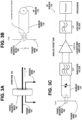
- Figures 2A to 2C and Figures 3A to 3C illustrate the high frequency components of the combined sensor, configured to output high frequency voltage used for determining an arc fault and tripping indication, in accordance with the invention.
- the ferromagnetic bead 100 becomes an inductive impedance in response to current signals with high frequencies in a power wire 102 passing through the bead 100. This may be used to provide an arc fault tripping indication in response to an occurrence of high frequency current signals in the power wire 102.
- a high frequency voltage sensor 110 ( Figures 2B and 2C ) has a first input terminal coupled to the first portion of the power wire 102 and a second input terminal coupled to the second portion of the power wire 102.
- High frequency current signal may be received by directly connecting to the power wire via isolation capacitors C1 and C2, a diode voltage clamp, and the analog front end (AFE).
- the analog front end (AFE) includes a band pass filter (BPF), a logarithmic amplifier, a low pass filter (LPF), and a processor for sampling and analyzing the signal using arc fault detection algorithms.
- An arc fault tripping circuit interrupter (AFCI) in the miniature circuit breaker 130 of Figure 6 may be configured to interrupt electrical current in the power wire 102, if an output from the high frequency voltage sensor 110 indicates that an arc-fault is detected in the power wire 102; the arc fault tripping circuit interrupter (AFCI) having an input coupled to the high frequency voltage sensor 110.
- AFCI arc fault tripping circuit interrupter
- a sensing wire 116 is positioned to pass once through the aperture 105 of the bead body 100.
- the sensing wire 116 is effectively a secondary coil for sensing the induced high frequency signals from the power wire 102.
- the sensing wire 116 is configured to sense an occurrence of high frequency current signals in the power wire 102 and to provide an arc fault tripping indication in response to an occurrence of high frequency current signals in the power wire 102.
- the high frequency current signal may be received by the sensor wire 116 serving as a single turn secondary loop connected to the analog front end (AFE).
- AFE analog front end
- High frequency current signal may be received by directly connecting to the sensor wire 116 via a diode voltage clamp and the analog front end (AFE).
- the analog front end (AFE) includes a band pass filter (BPF), a logarithmic amplifier, a low pass filter (LPF), and a processor for sampling and analyzing the signal using arc fault detection algorithms.
- Figures 4A to 4D illustrate the low frequency components of the combined sensor, configured to output low frequency voltage corresponding to the low frequency current for determining tripping times for arc fault detection and metering, in accordance with the invention.
- the powdered core bead body 100 includes the magnetic flux-density sensing device 106, such as a Hall-effect device or magnetic field sensor device, embedded in the air cavity 112 or 113 in the bead body 100, having a magnetic field sensing surface oriented substantially perpendicular to the circumferential periphery of the bead body 100.
- the bead body is configured to provide measurable magnetic flux through the magnetic flux-density sensing device 106, for currents in the power wire 102 having frequencies in the DC to 20kHz range.
- the measurable magnetic flux is detectable by the low frequency magnetic flux-density sensing device 106 or Hall-effect device, which is configured to output a voltage proportional to the low frequency current amplitude with the same frequency.
- the Hall-effect device 106 may include regulator, amplifier, and control modules in a large scale integrated circuit.
- This low frequency current may be used by an Arc Fault detection algorithm to determine the trip time, for example based on Underwriters Laboratories Inc. (UL) and International Electrotechnical Commission (IEC) standards.
- this low frequency current measurement may be used for power metering devices 119 or to determine power consumption within a protected branch.
- a low frequency voltage sensor 114 ( Figure 4D ) has an input terminal coupled to an output connection of the magnetic flux-density sensing device 106, configured to sense a low frequency variation of the magnetic flux in the bead body 100 sensed by the magnetic flux-density sensing device 106 and to output an indication of an over-current fault in the power wire 102.
- the power wire 102 may conduct a principal current that is either an alternating current (AC) or a direct current (DC), for example from a photovoltaic DC power source or DC batteries.
- the magnetic flux-density sensing device 106 may detect currents in the DC up to 20kHz range, is embedded into the powdered core bead body 100.
- the sensor 104 is not restricted to limitations of conventional current transformers (such as Rogowski sensors, or other dI/dt type current sensors), which require an AC current to work.
- Figure 5A is a graph illustrating the demodulated output from high frequency primary current sensing in a frequency range of 1MHz to 40MHz.
- the abscissa is the primary current from 10 -7 to 10 -1 Amperes.
- the ordinate is the RSSI ADC value from 0 to 2000 based on a specific Logarithmic Amplifier and ADC resolution.
- RSSI stands for Received Signal Strength Indication and ADC stands for Analog to Digital Converter.
- the traces compare various core lengths and sensor types.
- B1L stands for BEAD SENSOR FULL LENGTH CORE
- BHL stands for BEAD SENSOR 1 ⁇ 2 LENGTH CORE
- LIND stands for a REFERENCE SENSOR
- 13T stands for SENSOR WITH A 13 TURN SECONDARY WINDING
- B2L+Hall stands for BEAD SENSOR WITH DOUBLE LENGTH CORE AND HALL EFFECT DEVICE.
- a full length core is a relative length based on the inductance expected for the sensor to detect frequencies from 1MHz up to 40MHz and a certain output level for the logarithmic amplifier input impedance.
- the graph shows how changing just the length of the core, changes the sensitivity of the RF signal.
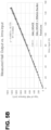
- Figure 5B is a graph of measured Hall output vs. the root mean square (RMS) primary current, illustrating low frequency sensing from the Hall Effect sensor, in accordance with the invention.
- the abscissa is the root mean square (RMS) primary current I from 0 to 160 Amperes.
- the ordinate is the maximum peak-peak voltage (Vpp) of the. Hall effect sensor in millivolts from 200 to 1600 mV.
- the traces compare a Hall-effect device, a Hall-effect device with a 200 Ohm burden, and a trend line.
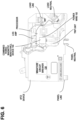
- FIG. 6 illustrates an example implementation of the combined low frequency and high frequency current sensor, in accordance with the invention.
- a miniature circuit breaker 130 includes the combined low frequency and high frequency current sensor 104.
- RF signals passing through the inductive impedance of the sensor 104 may be measured as a voltage drop between both terminals of the power wire 102.
- the impedance increases with the frequency and is proportional with the voltage drop across the terminals. This voltage may be filtered and amplified through an analog front end of an Arc Fault Circuit Interrupter (AFCI) device.
- AFCI Arc Fault Circuit Interrupter
- the powdered core bead sensor 104 includes a magnetic flux-density sensing device 1 06, such as a Hall-effect device or magnetic field sensor device, embedded in an air cavity 112 in the bead body 100, having a magnetic field sensing surface oriented substantially perpendicular to the circumferential periphery of the bead body.
- the bead body is configured to provide measurable magnetic flux through the magnetic flux-density sensing device, for currents in the power wire having frequencies in the DC up to 20kHz range.
- the measurable magnetic flux is detectable by the low frequency magnetic flux-density sensing device114, which is configured to output a voltage proportional to the low frequency current amplitude with the same frequency.
- This low frequency current may be used by an Arc Fault detection algorithm in the AFCI to determine the trip time, for example based on Underwriters Laboratories Inc. (UL) and International Electrotechnical Commission (IEC) standards.
- the miniature circuit breaker 130 is shown in Figure 6 , including the combined low frequency and high frequency current sensor 104, log amp, processor, load line, load neutral, power wire 102, trip unit, panel neutral terminal, panel line terminal, and AFCI device.
- the ferromagnetic powdered core bead body 100 may serve as a magnetic shield for the magnetic flux-density sensing device 106, to protect it from other stray magnetic fields.
- the shape of the powdered core bead body 100 provides a compact and low cost solution for sensing both high frequency arc faults, low frequency over-current faults, and for low frequency current measurement.
- the combined low frequency and high frequency current sensor 104 may be readily adapted for implementation in a monolithic solid-state design, which may be used, as an example for fastening to a bus bar.
Landscapes
- Physics & Mathematics (AREA)
- General Physics & Mathematics (AREA)
- Engineering & Computer Science (AREA)
- Power Engineering (AREA)
- Measuring Instrument Details And Bridges, And Automatic Balancing Devices (AREA)
- Emergency Protection Circuit Devices (AREA)
- Measurement Of Current Or Voltage (AREA)
- Breakers (AREA)
Description
- The present disclosure relates generally to fault detection in electrical circuits and more particularly to devices to sense both high frequency arc faults and low frequency over-current faults in power lines.
- Arcing faults are commonly defined as current through ionized gas between two ends of a broken conductor in a wire supplying power to a load or at a faulty contact or connector, between two conductors supplying a load, or between a conductor and ground. Arc-faults have high frequency spectral components in the load current signature of an arcing load. Arc-fault circuit interrupter devices include components such as a microprocessor, memory, filters, analog-to-digital converters, and other supporting components to analyze the current and rise-time signals to make a trip decision.
-
US 2017/0117699 A1 discloses an arc fault circuit interrupter which can include any one or more of three different sensors such as a high frequency sensor, and any one of lower frequency sensors such as a current sensor or a differential sensor. The arc fault circuit interrupter can be configured as an in line arc fault circuit interrupter installed in a wall box. In addition, the arc fault circuit interrupter can include a processor configured to determine any one of a series arc fault, or a parallel arc fault. -
US 6 128 169 A discloses an arc fault detector comprised as a stand-alone unit and in combination with a ground fault circuit interrupter (GFCI) functions to provide protection from potentially dangerous arc fault conditions. When combined with a GFCI, the combination arc fault/ground fault circuit interrupter (AFCI/GFCI) provides protection from both arc fault and ground fault conditions.
arc fault/ground fault circuit interrupter (AFCI/GFCI) provides protection from both arc fault and ground fault conditions. -
KR 10 1 454 203 B1 -
US 4 425 596 A discloses an electric circuit breaker including a current sensor composed of a Hall generator for detecting current overloads. Two secondary windings of a current transformer associated with the power line are connected to provide power to two separate power supply circuits. One circuit supplies power to a control circuit and the other circuit supplies control current to the Hall generator. The output voltage of the Hall generator is compared with a predetermined value in the control circuit. If a predetermined overload occurs, the control circuit energizes a trip coil for opening the power line. - A low cost and small device is very advantageous for accurately detecting arc faults, and also metering power consumption on branch circuits.
- The invention is defined in claim 1.
- In accordance with an example embodiment of the invention, a powdered core bead body, such as a ferromagnetic bead, is configured to become an inductive impedance to current signals with radio frequencies (RF) between 1MHz to 40MHz flowing through a power wire passing through the bead. These RF signals passing through this inductive impedance may be measured as a voltage drop between both terminals of the power wire. The impedance increases with the frequency and is proportional with the voltage drop across the terminals. This voltage may be filtered and amplified through an analog front end of an Arc Fault Circuit
-
KR 101 454 203 B1 -
US 4 425 596 A discloses an electric circuit breaker including a current sensor composed of a Hall generator for detecting current overloads. Two secondary windings of a current transformer associated with the power line are connected to provide power to two separate power supply circuits. One circuit supplies power to a control circuit and the other circuit supplies control current to the Hall generator. The output voltage of the Hall generator is compared with a predetermined value in the control circuit. If a predetermined overload occurs, the control circuit energizes a trip coil for opening the power line. -
EP 0 580 473 A1 - A low cost and small device is very advantageous for accurately detecting arc faults, and also metering power consumption on branch circuits.
- The invention is defined in claim 1.
- In accordance with an example embodiment of the invention, a powdered core bead body, such as a ferromagnetic bead, is configured to become an inductive impedance to current signals with radio frequencies (RF) between 1MHz to 40MHz flowing through a power wire passing through the bead. These RF signals passing through this inductive impedance may be measured as a voltage drop between both terminals of the power wire. The impedance increases with the frequency and is proportional with the voltage drop across the terminals. This voltage may be filtered and amplified through an analog front end of an Arc Fault Circuit Interrupter (AFCI) device. The powdered core bead body includes a magnetic flux-density sensing device, such as a Hall-effect device or magnetic field sensor device, embedded in a cavity in the bead body, having a magnetic field sensing surface oriented substantially perpendicular to the circumferential periphery of the bead body. The bead body is configured to provide measurable magnetic flux through the magnetic flux-density sensing device, for currents in the power wire having frequencies in the DC to 20kHz range. The measurable magnetic flux is detectable by the low frequency magnetic flux-density sensing device, which is configured to output a voltage proportional to the low frequency current amplitude with the same frequency. This low frequency current may be used by an Arc Fault detection algorithm to determine the trip time, for example based on Underwriters Laboratories Inc. (UL) and International Electrotechnical Commission (IEC) standards. Moreover, this low frequency current measurement may be used for power metering devices or to determine power consumption within a protected branch.
- In accordance with an example alternate embodiment of the invention, a sensing wire is positioned to pass once through an aperture of the bead body. The sensing wire is configured to sense an occurrence of high frequency current signals in the power wire and to provide an arc fault tripping indication in response to an occurrence of high frequency current signals in the power wire.
- The resulting invention provides a smaller and simpler device for both arc-fault detection and over-current protection.
- Example embodiments of the invention are depicted in the accompanying drawings that are briefly described as follows:
-
Figures 1A to 1I illustrate different examples of the combined low frequency and high frequency current sensor, in accordance with the invention. -
Figures 2A to 2C andFigures 3A to 3C illustrate the high frequency components of the combined sensor, configured to output high frequency voltage used for determining an arc fault and tripping indication, in accordance with the invention. -
Figures 4A to 4D illustrate the low frequency components of the combined sensor, configured to output low frequency voltage corresponding to the low frequency current for determining tripping times for arc fault detection and metering, in accordance with the invention. -
Figure 5A is a graph illustrating the peak amplitude of demodulated output from high frequency primary current sensing andFigure 5B is a graph illustrating low frequency sensing from the Hall Effect sensor, in accordance with the invention. -
Figure 6 illustrates an example implementation of the combined low frequency and high frequency current sensor, in accordance with the invention. -
Figures 1A to 1I illustrate examples of a combined low frequency and high frequencycurrent sensor 104 in accordance with the invention. -
Figure 1A is a cross sectional view of the combined low frequency and high frequencycurrent sensor 104, in accordance with the invention. A powderedcore bead body 100 has a generally cylindrical shape with a centralizedcircular aperture 105 through thebead body 100. Apower wire 102 has a first portion passing into a first end of the aperture 104 (Figure 1D ) and through thebead body 100 and a second portion passing out of a second end of theaperture 105. The powderedcore bead body 100 has a low relative magnetic permeability µ=20 up to 120, to minimize saturation by high currents in the power wire. Typical magnetic materials suitable for the powderedcore bead body 100 include ferrites and magnetic oxides.Magnetic flux lines 103 shown inFigure 1 A , are directed according to the right-hand rule, in a counterclockwise direction through the cylindrical body of theferromagnetic bead 100, produced by an electric current flowing in thepower wire 102 and directed out of the page toward the reader. - An air cavity is formed in the
bead body 100, which may be partially through the cylinder in a radial direction, as shown by thepartial air cavity 112 ofFigures 1A and1F , or completely through the cylinder in the radial direction, as shown by the throughair cavity 113 ofFigure 1H . In the case of either thepartial air cavity 112 or the throughair cavity 113, the sidewalls of the cavity are substantially perpendicular to the circumferential periphery of the toroid. Thecavity main portion 107 of thebead 100 by various manufacturing processes, such as by molding the powdered core material around an insert having a negative shape of the cavity, or by cutting the cavity into themain portion 107 of thebead 100 by drilling, mechanical machining, or electrical discharge machining. - A magnetic flux-
density sensing device 106 is embedded in thepartial air cavity 112 or the throughair cavity 113 of thebead body 100, having a magnetic field sensing surface oriented substantially perpendicular to the circumferential periphery of thebead body 100. The magnetic flux-density sensing device may be a Hall-effect device, magneto-diode, magneto-transistor, magneto-optical sensor, fluxgate magnetometer, or search coil magnetic field sensor. The sensitivity of thesensor 104 may be controlled by the material of theferromagnetic bead 100 and its length/size. MostHall effect sensors 106 have a linear range between a saturating magnetic flux in one direction -Bsat and a saturating magnetic flux in the opposite direction +Bsat. Based on the magnetic flux measurement range required, a Hall-effect sensor 106 outputs a voltage proportional to the magnetic flux corresponding to the low frequency current in thepower wire 102. -
Figure 1B shows orthographic projections of theferromagnetic bead 100 from the left end, front, and right end, showing thepartial cavity 112 penetrating partially through thetoroidal bead body 100.Figure 1C shows a magnified, cross sectional view of the relationship of theferromagnetic bead 100 and thepower wire 102 in theaperture 105. Thepartial cavity 112 shown inFigure 1C has been formed only partway through themain portion 107 of theferromagnetic bead 100, leaving a remaining thickness of theferromagnetic bead 100, referred to here as the shieldingbridge portion 109. The magnetic flux-density sensing device 106 or Hall-effect device is embedded within thepartial cavity 112.Magnetic flux lines 103 produced by the electric current flowing in thepower wire 102, pass into theferromagnetic bead 100 and are a concentratedmagnetic flux 111 in the shieldingbridge portion 109. A small portion of themagnetic flux 103 in themain portion 107 of thebead 100 passes as afringing flux 117 through thepartial air cavity 112, which is the magnetic flux incident on and measured by the magnetic flux-density sensing device 106 or Hall-effect device. Due to the concentratedmagnetic flux 111 in the shieldingbridge portion 109, the shieldingbridge portion 109 serves to shield the Hall-effect device 106 from variations in the magnitude of themagnetic flux 103 in theferromagnetic bead 100, due to variations in the distance of thepower wire 102 from the inner edge of the cylinder at the shieldingbridge portion 109. -
Figures 1D, 1F, and 1F show several views of the combined low frequency and high frequencycurrent sensor 104, with thepartial air cavity 112.Figures 1G, 1H, and 1I show several views of the combined low frequency and high frequencycurrent sensor 104, with the throughair cavity 113. -
Figures 2A to 2C andFigures 3A to 3C illustrate the high frequency components of the combined sensor, configured to output high frequency voltage used for determining an arc fault and tripping indication, in accordance with the invention. Theferromagnetic bead 100 becomes an inductive impedance in response to current signals with high frequencies in apower wire 102 passing through thebead 100. This may be used to provide an arc fault tripping indication in response to an occurrence of high frequency current signals in thepower wire 102. - A high frequency voltage sensor 110 (
Figures 2B and 2C ) has a first input terminal coupled to the first portion of thepower wire 102 and a second input terminal coupled to the second portion of thepower wire 102. High frequency current signal may be received by directly connecting to the power wire via isolation capacitors C1 and C2, a diode voltage clamp, and the analog front end (AFE). The analog front end (AFE) includes a band pass filter (BPF), a logarithmic amplifier, a low pass filter (LPF), and a processor for sampling and analyzing the signal using arc fault detection algorithms. - An arc fault tripping circuit interrupter (AFCI) in the
miniature circuit breaker 130 ofFigure 6 , may be configured to interrupt electrical current in thepower wire 102, if an output from the highfrequency voltage sensor 110 indicates that an arc-fault is detected in thepower wire 102; the arc fault tripping circuit interrupter (AFCI) having an input coupled to the highfrequency voltage sensor 110. - In accordance with an example alternate embodiment of the invention shown in
Figures 3A to 3C , asensing wire 116 is positioned to pass once through theaperture 105 of thebead body 100. Thesensing wire 116 is effectively a secondary coil for sensing the induced high frequency signals from thepower wire 102. Thesensing wire 116 is configured to sense an occurrence of high frequency current signals in thepower wire 102 and to provide an arc fault tripping indication in response to an occurrence of high frequency current signals in thepower wire 102. The high frequency current signal may be received by thesensor wire 116 serving as a single turn secondary loop connected to the analog front end (AFE). High frequency current signal may be received by directly connecting to thesensor wire 116 via a diode voltage clamp and the analog front end (AFE). The analog front end (AFE) includes a band pass filter (BPF), a logarithmic amplifier, a low pass filter (LPF), and a processor for sampling and analyzing the signal using arc fault detection algorithms. -
Figures 4A to 4D illustrate the low frequency components of the combined sensor, configured to output low frequency voltage corresponding to the low frequency current for determining tripping times for arc fault detection and metering, in accordance with the invention. - The powdered
core bead body 100 includes the magnetic flux-density sensing device 106, such as a Hall-effect device or magnetic field sensor device, embedded in theair cavity bead body 100, having a magnetic field sensing surface oriented substantially perpendicular to the circumferential periphery of thebead body 100. The bead body is configured to provide measurable magnetic flux through the magnetic flux-density sensing device 106, for currents in thepower wire 102 having frequencies in the DC to 20kHz range. The measurable magnetic flux is detectable by the low frequency magnetic flux-density sensing device 106 or Hall-effect device, which is configured to output a voltage proportional to the low frequency current amplitude with the same frequency. The Hall-effect device 106 may include regulator, amplifier, and control modules in a large scale integrated circuit. This low frequency current may be used by an Arc Fault detection algorithm to determine the trip time, for example based on Underwriters Laboratories Inc. (UL) and International Electrotechnical Commission (IEC) standards. Moreover, this low frequency current measurement may be used forpower metering devices 119 or to determine power consumption within a protected branch. - A low frequency voltage sensor 114 (
Figure 4D ) has an input terminal coupled to an output connection of the magnetic flux-density sensing device 106, configured to sense a low frequency variation of the magnetic flux in thebead body 100 sensed by the magnetic flux-density sensing device 106 and to output an indication of an over-current fault in thepower wire 102. - The
power wire 102 may conduct a principal current that is either an alternating current (AC) or a direct current (DC), for example from a photovoltaic DC power source or DC batteries. The magnetic flux-density sensing device 106 may detect currents in the DC up to 20kHz range, is embedded into the powderedcore bead body 100. Thesensor 104 is not restricted to limitations of conventional current transformers (such as Rogowski sensors, or other dI/dt type current sensors), which require an AC current to work. -
Figure 5A is a graph illustrating the demodulated output from high frequency primary current sensing in a frequency range of 1MHz to 40MHz. The abscissa is the primary current from 10-7 to 10-1 Amperes. The ordinate is the RSSI ADC value from 0 to 2000 based on a specific Logarithmic Amplifier and ADC resolution. RSSI stands for Received Signal Strength Indication and ADC stands for Analog to Digital Converter. The traces compare various core lengths and sensor types. InFigure 5A , B1L stands for BEAD SENSOR FULL LENGTH CORE, BHL stands for BEAD SENSOR ½ LENGTH CORE, LIND stands for a REFERENCE SENSOR, 13T stands for SENSOR WITH A 13 TURN SECONDARY WINDING, and B2L+Hall stands for BEAD SENSOR WITH DOUBLE LENGTH CORE AND HALL EFFECT DEVICE. Note: A full length core is a relative length based on the inductance expected for the sensor to detect frequencies from 1MHz up to 40MHz and a certain output level for the logarithmic amplifier input impedance. The graph shows how changing just the length of the core, changes the sensitivity of the RF signal. -
Figure 5B is a graph of measured Hall output vs. the root mean square (RMS) primary current, illustrating low frequency sensing from the Hall Effect sensor, in accordance with the invention. The abscissa is the root mean square (RMS) primary current I from 0 to 160 Amperes. The ordinate is the maximum peak-peak voltage (Vpp) of the. Hall effect sensor in millivolts from 200 to 1600 mV. The traces compare a Hall-effect device, a Hall-effect device with a 200 Ohm burden, and a trend line. -
Figure 6 illustrates an example implementation of the combined low frequency and high frequency current sensor, in accordance with the invention. Aminiature circuit breaker 130 includes the combined low frequency and high frequencycurrent sensor 104. RF signals passing through the inductive impedance of thesensor 104 may be measured as a voltage drop between both terminals of thepower wire 102. The impedance increases with the frequency and is proportional with the voltage drop across the terminals. This voltage may be filtered and amplified through an analog front end of an Arc Fault Circuit Interrupter (AFCI) device. The powderedcore bead sensor 104 includes a magnetic flux-density sensing device 1 06, such as a Hall-effect device or magnetic field sensor device, embedded in anair cavity 112 in thebead body 100, having a magnetic field sensing surface oriented substantially perpendicular to the circumferential periphery of the bead body. The bead body is configured to provide measurable magnetic flux through the magnetic flux-density sensing device, for currents in the power wire having frequencies in the DC up to 20kHz range. The measurable magnetic flux is detectable by the low frequency magnetic flux-density sensing device114, which is configured to output a voltage proportional to the low frequency current amplitude with the same frequency. This low frequency current may be used by an Arc Fault detection algorithm in the AFCI to determine the trip time, for example based on Underwriters Laboratories Inc. (UL) and International Electrotechnical Commission (IEC) standards. Theminiature circuit breaker 130 is shown inFigure 6 , including the combined low frequency and high frequencycurrent sensor 104, log amp, processor, load line, load neutral,power wire 102, trip unit, panel neutral terminal, panel line terminal, and AFCI device. - The ferromagnetic powdered
core bead body 100 may serve as a magnetic shield for the magnetic flux-density sensing device 106, to protect it from other stray magnetic fields. The shape of the powderedcore bead body 100 provides a compact and low cost solution for sensing both high frequency arc faults, low frequency over-current faults, and for low frequency current measurement. The combined low frequency and high frequencycurrent sensor 104 may be readily adapted for implementation in a monolithic solid-state design, which may be used, as an example for fastening to a bus bar. - Among the advantages of the invention, are the following:
- Reduced number of sensors for low and high frequency currents:
- a) Single package for two sensors; smaller footprint
- Low cost manufacturing sensor:
- a) Solid design;
- b) No winding wires;
- c) Single bead with low relative permeability µ=20 up to 120;
- d) No passive or active integrator circuit required; and
- e) Fast response.
- Simplicity in installation, reduced assembly cost:
- a) The bead sensor may be molded to a single core for easy assembly.
- Optimization capability for space and sensitivity.
- Measurement of low frequency currents down to DC.
- Although specific example embodiments of the invention have been disclosed, persons of skill in the art will appreciate that changes may be made to the details described for the specific example embodiments, without departing from the scope of the invention as defined in the attached claims.
Claims (12)
- A combined low frequency and high frequency current sensor (104), comprising:a powdered core bead body (100) composed of a ferromagnetic, ferrite, or magnetic oxide material having a generally toroidal shape with a radial thickness extending between a circumferential periphery and an inner periphery surrounding a centralized circular aperture (105) through which passes a current carrying power wire (102), and an air cavity (112) formed in the powdered core bead body (100) with sidewalls substantially perpendicular to the circumferential periphery and extending radially inwardly for a distance less than the radial thickness forming a bottom of the cavity separated from the inner periphery of the powdered core bead body (100) surrounding the centralized circular aperture (105) by a remaining thickness of the powdered core bead body (100) forming a shielding bridge portion (109), configured to provide a magnetic shield for the air cavity from variations in magnetic flux due to variations in distance of the power wire (102) from the inner periphery of the powdered core bead body (100) to enable measurement of magnetic flux in the air cavity;a magnetic flux-density sensing device (106) embedded in the air cavity (112) in the powdered core bead body (100), having a magnetic field sensing surface oriented substantially perpendicular to the circumferential periphery of the powdered core bead body (100), configured to measure magnetic flux through the magnetic flux-density sensing device (106) in response to current signals in the power wire (102); anda low frequency voltage sensor (114) having an input terminal coupled to an output connection of the magnetic flux-density sensing device (106), configured to sense a variation of the magnetic flux in the powdered core bead body (100), sensed by the magnetic flux-density sensing device (106) and to output an indication of an over-current fault in the power wire (102).
- The combined low frequency and high frequency current sensor (104) of claim 1, further comprising:
a sensing wire (116) positioned to pass once through the aperture (105) of the bead body (100), the sensing wire (116) configured sense an occurrence of high frequency current signals in the power wire (102) and to provide an arc fault tripping indication in response to an occurrence of high frequency current signals in the power wire (102). - The combined low frequency and high frequency current sensor (104) of any of the preceding claims, further comprising:
a voltage sensor (114) having a first input terminal coupled to a first portion of the power wire (102) and a second input terminal coupled to a second portion of the power wire (102), configured to provide an arc fault tripping indication in response to an occurrence of current signals in the power wire (102). - The combined low frequency and high frequency current sensor (104) of claim 3, further comprising:
an arc fault tripping circuit configured to interrupt or trip electrical current in the power wire (102), if an output from the voltage sensor (114) indicates that an arc-fault is detected, the arc fault tripping circuit having an input coupled to the voltage sensor (114). - The combined low frequency and high frequency current sensor (104) of any of the preceding claims, further comprising:
an over-current fault tripping circuit configured to interrupt or trip electrical current in the power wire (102), if an output from the low frequency voltage sensor (114) indicates that an over-current fault or a ground-fault is detected, the over-current fault tripping circuit having an input coupled to the low frequency voltage sensor (114). - The combined low frequency and high frequency current sensor (104) of any of the preceding claims, wherein the core bead body (100) is configured to become an inductive impedance to current signals in the power wire (102) with frequencies in the 1MHz to 40MHz range.
- The combined low frequency and high frequency current sensor (104) of any of the preceding claims, wherein the core bead body (100) is configured to provide measurable magnetic flux through the magnetic flux-density sensing device (106), for currents in the power wire (102) having frequencies from DC up to 20kHz, the measurable magnetic flux being detectable by the magnetic flux-density sensing device (106), which is configured to provide a fault tripping indication.
- The combined low frequency and high frequency current sensor (104) of claim 2, further comprising:
a voltage sensor (114) having a first input terminal coupled to a first portion of the sensing wire and a second input terminal coupled to a second portion of the sensing wire (116), configured to sense an occurrence of high frequency current signals in the power wire (102) and to provide an arc fault tripping indication in response to an occurrence of high frequency current signals in the power wire (102). - The combined low frequency and high frequency current sensor (104) of any of the preceding claims, wherein the core bead body (100) has a generally cylindrical shape with the central aperture (105) through the bead body (100) through which the power wire (102) passes, and has the air cavity (112) in the bead body (100) being formed only partially through the cylindrical bead, leaving the remaining thickness of the bead, which serves to shield the magnetic flux-density sensing device (106) from variations in magnitude of magnetic flux in the bead, due to variations in distance of the power wire (102) from an inner edge of the toroid.
- The combined low frequency and high frequency current sensor (104) of any of the preceding claims, wherein the power wire (102) conducts a principal current that is either alternating current (AC) or direct current (DC).
- The combined low frequency and high frequency current sensor (104) of any of the preceding claims, wherein the core bead body (100) is composed of a ferromagnetic material.
- The combined low frequency and high frequency current sensor (104) of any of the preceding claims, wherein the magnetic flux-density sensing device (106) is a Hall-effect device.
Applications Claiming Priority (1)
| Application Number | Priority Date | Filing Date | Title |
|---|---|---|---|
| US16/213,472 US11079424B2 (en) | 2018-12-07 | 2018-12-07 | Combined low frequency and high frequency current sensor |
Publications (2)
| Publication Number | Publication Date |
|---|---|
| EP3663777A1 EP3663777A1 (en) | 2020-06-10 |
| EP3663777B1 true EP3663777B1 (en) | 2024-05-22 |
Family
ID=68808039
Family Applications (1)
| Application Number | Title | Priority Date | Filing Date |
|---|---|---|---|
| EP19213921.0A Active EP3663777B1 (en) | 2018-12-07 | 2019-12-05 | Combined low frequency and high frequency current sensor |
Country Status (3)
| Country | Link |
|---|---|
| US (1) | US11079424B2 (en) |
| EP (1) | EP3663777B1 (en) |
| CN (1) | CN111289792B (en) |
Families Citing this family (14)
| Publication number | Priority date | Publication date | Assignee | Title |
|---|---|---|---|---|
| US11204396B2 (en) | 2018-06-12 | 2021-12-21 | Eaton Intelligent Power Limited | Electrical system |
| DE102019200333A1 (en) * | 2019-01-14 | 2020-07-16 | Phoenix Contact Gmbh & Co. Kg | Measuring system for recording faults on the lines of a device or system |
| JP7357228B2 (en) * | 2020-03-11 | 2023-10-06 | パナソニックIpマネジメント株式会社 | Arc detection equipment, power conditioners, indoor wiring systems, breakers, solar panels, solar panel attachment modules and connection boxes |
| CN113035551A (en) * | 2021-03-16 | 2021-06-25 | 东莞市必德电子科技有限公司 | Production process of paster magnetic beads |
| CN115621096A (en) * | 2021-07-16 | 2023-01-17 | 施耐德电气(澳大利亚)有限公司 | Opening and closing mechanism and leakage protection equipment |
| CN113520521B (en) * | 2021-08-30 | 2023-11-03 | 江苏朴芃医疗科技有限公司 | Current peak detection device, high voltage generator and vascular calcification treatment equipment |
| US12196784B1 (en) * | 2022-01-18 | 2025-01-14 | National Technology & Engineering Solutions Of Sandia, Llc | Magnetostrictive current sensor method and system |
| CN115656597A (en) * | 2022-03-21 | 2023-01-31 | 昆明理工大学 | Composite passive current sensor for broadband current measurement |
| WO2024062401A1 (en) | 2022-09-21 | 2024-03-28 | Basis NZ Limited | Current detection device and related devices, systems and methods thereof |
| CN116165482A (en) * | 2023-01-13 | 2023-05-26 | 福建新能电气有限公司 | Single-wire self-coupling arc fault detection method |
| CN116936236B (en) * | 2023-06-29 | 2024-05-31 | 上海正泰电源系统有限公司 | Detection transformer and method for improving direct current arc detection precision |
| WO2025033425A1 (en) * | 2023-08-10 | 2025-02-13 | 日置電機株式会社 | Current sensor, measuring device, and measuring method |
| CN121816505A (en) * | 2023-08-10 | 2026-04-07 | 日置电机株式会社 | Current sensor, measurement device, and measurement method |
| KR102943908B1 (en) * | 2024-07-03 | 2026-03-26 | 엠케이에스코리아 유한회사 | Multi-Frequency Precision Voltage and Current Sensor |
Citations (2)
| Publication number | Priority date | Publication date | Assignee | Title |
|---|---|---|---|---|
| US4914383A (en) * | 1985-10-10 | 1990-04-03 | Wilkerson A W | Non-contact ammeter |
| EP0580473A1 (en) * | 1992-07-15 | 1994-01-26 | ABB CONTROL Société Anonyme | Current transformer with feedback for direct currents, alternative currents or pulsed currents |
Family Cites Families (24)
| Publication number | Priority date | Publication date | Assignee | Title |
|---|---|---|---|---|
| US4425596A (en) | 1980-09-26 | 1984-01-10 | Tokyo Shibaura Denki Kabushiki Kaisha | Electric circuit breaker |
| US4858054A (en) | 1985-05-07 | 1989-08-15 | Franklin Frederick F | Protective circuits and devices for the prevention of fires |
| FR2624617B1 (en) | 1987-12-11 | 1990-05-11 | Europ Agence Spatiale | MAGNETICALLY COUPLED ELECTRIC CURRENT MEASURING APPARATUS |
| US6128169A (en) | 1997-12-19 | 2000-10-03 | Leviton Manufacturing Co., Inc. | Arc fault detector with circuit interrupter and early arc fault detection |
| US6625550B1 (en) * | 1998-02-19 | 2003-09-23 | Square D Company | Arc fault detection for aircraft |
| US6426634B1 (en) | 1999-03-29 | 2002-07-30 | George A. Spencer | Circuit breaker with integrated self-test enhancements |
| WO2005033716A1 (en) * | 2003-10-01 | 2005-04-14 | Eaton Corporation | System and method for current sensing using anti-differential, error correcting current sensing |
| US7180299B2 (en) | 2003-12-22 | 2007-02-20 | Leviton Manufacturing Co., Inc. | Arc fault detector |
| US7190561B2 (en) * | 2004-09-09 | 2007-03-13 | Sensata Technologies, Inc. | Apparatus for detecting arc faults |
| US8023235B2 (en) * | 2006-10-31 | 2011-09-20 | Siemens Industry, Inc. | Multifunctional residential circuit breaker |
| US8218274B2 (en) * | 2009-12-15 | 2012-07-10 | Eaton Corporation | Direct current arc fault circuit interrupter, direct current arc fault detector, noise blanking circuit for a direct current arc fault circuit interrupter, and method of detecting arc faults |
| US8421473B2 (en) * | 2010-05-10 | 2013-04-16 | Eaton Corporation | Apparatus and method to detect a series arc fault of an electrical circuit |
| US20120319489A1 (en) * | 2011-06-15 | 2012-12-20 | Mccaslin Shawn R | Power Shuffling Solar String Equalization System |
| US8599523B1 (en) * | 2011-07-29 | 2013-12-03 | Leviton Manufacturing Company, Inc. | Arc fault circuit interrupter |
| JP5435825B2 (en) * | 2012-01-05 | 2014-03-05 | 日本航空電子工業株式会社 | Connector and connector assembly |
| KR20140125585A (en) | 2013-04-19 | 2014-10-29 | 최종운 | Apparatus for monitering plasma V-I Probe |
| JP6188399B2 (en) | 2013-04-24 | 2017-08-30 | 日置電機株式会社 | Current sensor |
| DE102013225645A1 (en) | 2013-12-11 | 2015-06-11 | Deere & Company | Current sensor and control circuit |
| KR101454203B1 (en) | 2014-07-16 | 2014-11-04 | 주식회사 태강전기 | Low current arc detecting system |
| US9979178B2 (en) * | 2014-09-08 | 2018-05-22 | Pass & Seymour, Inc. | Arc fault circuit interrupter with surge suppression |
| KR102539688B1 (en) * | 2016-04-28 | 2023-06-07 | 엘에스일렉트릭(주) | Leakage Current Detector |
| JP6508163B2 (en) * | 2016-10-31 | 2019-05-08 | 横河電機株式会社 | Current measurement device |
| EP3386051B1 (en) * | 2017-04-04 | 2021-06-23 | ABB Schweiz AG | Electronic protection device for detecting arcing fault |
| CN107085158A (en) * | 2017-06-20 | 2017-08-22 | 浙江中科城安消防科技有限公司 | A kind of fault arc detection device and method for gathering communication |
-
2018
- 2018-12-07 US US16/213,472 patent/US11079424B2/en active Active
-
2019
- 2019-12-05 EP EP19213921.0A patent/EP3663777B1/en active Active
- 2019-12-09 CN CN201911248261.4A patent/CN111289792B/en active Active
Patent Citations (2)
| Publication number | Priority date | Publication date | Assignee | Title |
|---|---|---|---|---|
| US4914383A (en) * | 1985-10-10 | 1990-04-03 | Wilkerson A W | Non-contact ammeter |
| EP0580473A1 (en) * | 1992-07-15 | 1994-01-26 | ABB CONTROL Société Anonyme | Current transformer with feedback for direct currents, alternative currents or pulsed currents |
Also Published As
| Publication number | Publication date |
|---|---|
| US20200182921A1 (en) | 2020-06-11 |
| US11079424B2 (en) | 2021-08-03 |
| CN111289792B (en) | 2024-06-25 |
| CN111289792A (en) | 2020-06-16 |
| EP3663777A1 (en) | 2020-06-10 |
Similar Documents
| Publication | Publication Date | Title |
|---|---|---|
| US11079424B2 (en) | Combined low frequency and high frequency current sensor | |
| US8542021B2 (en) | Multi-pole arcing fault circuit breaker including a neutral current sensor | |
| KR101929436B1 (en) | Current measuring systems and methods of assembling the same | |
| US5943204A (en) | Electronic trip unit with dedicated override current sensor | |
| KR101454203B1 (en) | Low current arc detecting system | |
| US7944654B2 (en) | Multiple-pole circuit breaker with shared current sensor for arcing fault detection | |
| EP3663778B1 (en) | Low cost high frequency sensor for arc-fault detection | |
| US7567074B2 (en) | Measuring device for measuring differential current, trip module comprising one such measuring device and switchgear unit having one such module | |
| US9343895B2 (en) | Protection relay for sensitive earth fault protection | |
| US20100149700A1 (en) | Power distribution system and electrical switching apparatus employing a filter trap circuit to provide arc fault trip coordination | |
| US7224559B2 (en) | Differential current detection | |
| EP2710617B1 (en) | Ac/dc current transformer | |
| EP3496222B1 (en) | Earth leakage circuit breaker based on the ratio of a specific harmonic current component to the fundamental wave current component | |
| US7359167B2 (en) | Corded leakage-current detection and interruption apparatus | |
| CN117269584B (en) | Current detection module | |
| US4843310A (en) | Electricity meter with arrangement for monitoring core saturation incidents | |
| JP2002311061A (en) | Processor for electric power | |
| CN105359365B (en) | Method and apparatus for complex, universal ground fault protection in medium and high voltage power systems | |
| KR20250141073A (en) | Power Protection Apparatus | |
| US11617269B2 (en) | Current measuring device for an electric power protection system | |
| CN118191392A (en) | Accessory equipment for low voltage switches | |
| WO2024203288A1 (en) | Electric current sensor, and measuring device | |
| JP2024144126A (en) | Current sensor and measuring device | |
| JP2023051300A (en) | Current transformer-integrated current sensor and circuit breaker | |
| GB2152681A (en) | Device for detecting current flowing in a conductor |
Legal Events
| Date | Code | Title | Description |
|---|---|---|---|
| PUAI | Public reference made under article 153(3) epc to a published international application that has entered the european phase |
Free format text: ORIGINAL CODE: 0009012 |
|
| STAA | Information on the status of an ep patent application or granted ep patent |
Free format text: STATUS: THE APPLICATION HAS BEEN PUBLISHED |
|
| AK | Designated contracting states |
Kind code of ref document: A1 Designated state(s): AL AT BE BG CH CY CZ DE DK EE ES FI FR GB GR HR HU IE IS IT LI LT LU LV MC MK MT NL NO PL PT RO RS SE SI SK SM TR |
|
| AX | Request for extension of the european patent |
Extension state: BA ME |
|
| STAA | Information on the status of an ep patent application or granted ep patent |
Free format text: STATUS: REQUEST FOR EXAMINATION WAS MADE |
|
| 17P | Request for examination filed |
Effective date: 20201208 |
|
| RBV | Designated contracting states (corrected) |
Designated state(s): AL AT BE BG CH CY CZ DE DK EE ES FI FR GB GR HR HU IE IS IT LI LT LU LV MC MK MT NL NO PL PT RO RS SE SI SK SM TR |
|
| STAA | Information on the status of an ep patent application or granted ep patent |
Free format text: STATUS: EXAMINATION IS IN PROGRESS |
|
| 17Q | First examination report despatched |
Effective date: 20221208 |
|
| GRAP | Despatch of communication of intention to grant a patent |
Free format text: ORIGINAL CODE: EPIDOSNIGR1 |
|
| STAA | Information on the status of an ep patent application or granted ep patent |
Free format text: STATUS: GRANT OF PATENT IS INTENDED |
|
| INTG | Intention to grant announced |
Effective date: 20231214 |
|
| RIN1 | Information on inventor provided before grant (corrected) |
Inventor name: ISAACSON, ROBERT B. Inventor name: JAKUPI, ANDI Inventor name: RODRIGUES, CARLTON T. |
|
| GRAS | Grant fee paid |
Free format text: ORIGINAL CODE: EPIDOSNIGR3 |
|
| GRAA | (expected) grant |
Free format text: ORIGINAL CODE: 0009210 |
|
| STAA | Information on the status of an ep patent application or granted ep patent |
Free format text: STATUS: THE PATENT HAS BEEN GRANTED |
|
| AK | Designated contracting states |
Kind code of ref document: B1 Designated state(s): AL AT BE BG CH CY CZ DE DK EE ES FI FR GB GR HR HU IE IS IT LI LT LU LV MC MK MT NL NO PL PT RO RS SE SI SK SM TR |
|
| REG | Reference to a national code |
Ref country code: GB Ref legal event code: FG4D |
|
| REG | Reference to a national code |
Ref country code: CH Ref legal event code: EP |
|
| REG | Reference to a national code |
Ref country code: DE Ref legal event code: R096 Ref document number: 602019052536 Country of ref document: DE |
|
| REG | Reference to a national code |
Ref country code: IE Ref legal event code: FG4D |
|
| REG | Reference to a national code |
Ref country code: LT Ref legal event code: MG9D |
|
| REG | Reference to a national code |
Ref country code: NL Ref legal event code: MP Effective date: 20240522 |
|
| PG25 | Lapsed in a contracting state [announced via postgrant information from national office to epo] |
Ref country code: IS Free format text: LAPSE BECAUSE OF FAILURE TO SUBMIT A TRANSLATION OF THE DESCRIPTION OR TO PAY THE FEE WITHIN THE PRESCRIBED TIME-LIMIT Effective date: 20240922 |
|
| PG25 | Lapsed in a contracting state [announced via postgrant information from national office to epo] |
Ref country code: BG Free format text: LAPSE BECAUSE OF FAILURE TO SUBMIT A TRANSLATION OF THE DESCRIPTION OR TO PAY THE FEE WITHIN THE PRESCRIBED TIME-LIMIT Effective date: 20240522 |
|
| PG25 | Lapsed in a contracting state [announced via postgrant information from national office to epo] |
Ref country code: HR Free format text: LAPSE BECAUSE OF FAILURE TO SUBMIT A TRANSLATION OF THE DESCRIPTION OR TO PAY THE FEE WITHIN THE PRESCRIBED TIME-LIMIT Effective date: 20240522 Ref country code: FI Free format text: LAPSE BECAUSE OF FAILURE TO SUBMIT A TRANSLATION OF THE DESCRIPTION OR TO PAY THE FEE WITHIN THE PRESCRIBED TIME-LIMIT Effective date: 20240522 |
|
| PG25 | Lapsed in a contracting state [announced via postgrant information from national office to epo] |
Ref country code: GR Free format text: LAPSE BECAUSE OF FAILURE TO SUBMIT A TRANSLATION OF THE DESCRIPTION OR TO PAY THE FEE WITHIN THE PRESCRIBED TIME-LIMIT Effective date: 20240823 |
|
| PG25 | Lapsed in a contracting state [announced via postgrant information from national office to epo] |
Ref country code: PT Free format text: LAPSE BECAUSE OF FAILURE TO SUBMIT A TRANSLATION OF THE DESCRIPTION OR TO PAY THE FEE WITHIN THE PRESCRIBED TIME-LIMIT Effective date: 20240923 |
|
| REG | Reference to a national code |
Ref country code: AT Ref legal event code: MK05 Ref document number: 1689180 Country of ref document: AT Kind code of ref document: T Effective date: 20240522 |
|
| PG25 | Lapsed in a contracting state [announced via postgrant information from national office to epo] |
Ref country code: NL Free format text: LAPSE BECAUSE OF FAILURE TO SUBMIT A TRANSLATION OF THE DESCRIPTION OR TO PAY THE FEE WITHIN THE PRESCRIBED TIME-LIMIT Effective date: 20240522 |
|
| PG25 | Lapsed in a contracting state [announced via postgrant information from national office to epo] |
Ref country code: ES Free format text: LAPSE BECAUSE OF FAILURE TO SUBMIT A TRANSLATION OF THE DESCRIPTION OR TO PAY THE FEE WITHIN THE PRESCRIBED TIME-LIMIT Effective date: 20240522 |
|
| PG25 | Lapsed in a contracting state [announced via postgrant information from national office to epo] |
Ref country code: AT Free format text: LAPSE BECAUSE OF FAILURE TO SUBMIT A TRANSLATION OF THE DESCRIPTION OR TO PAY THE FEE WITHIN THE PRESCRIBED TIME-LIMIT Effective date: 20240522 |
|
| PG25 | Lapsed in a contracting state [announced via postgrant information from national office to epo] |
Ref country code: PL Free format text: LAPSE BECAUSE OF FAILURE TO SUBMIT A TRANSLATION OF THE DESCRIPTION OR TO PAY THE FEE WITHIN THE PRESCRIBED TIME-LIMIT Effective date: 20240522 |
|
| PG25 | Lapsed in a contracting state [announced via postgrant information from national office to epo] |
Ref country code: LV Free format text: LAPSE BECAUSE OF FAILURE TO SUBMIT A TRANSLATION OF THE DESCRIPTION OR TO PAY THE FEE WITHIN THE PRESCRIBED TIME-LIMIT Effective date: 20240522 |
|
| PG25 | Lapsed in a contracting state [announced via postgrant information from national office to epo] |
Ref country code: PT Free format text: LAPSE BECAUSE OF FAILURE TO SUBMIT A TRANSLATION OF THE DESCRIPTION OR TO PAY THE FEE WITHIN THE PRESCRIBED TIME-LIMIT Effective date: 20240923 Ref country code: PL Free format text: LAPSE BECAUSE OF FAILURE TO SUBMIT A TRANSLATION OF THE DESCRIPTION OR TO PAY THE FEE WITHIN THE PRESCRIBED TIME-LIMIT Effective date: 20240522 Ref country code: NO Free format text: LAPSE BECAUSE OF FAILURE TO SUBMIT A TRANSLATION OF THE DESCRIPTION OR TO PAY THE FEE WITHIN THE PRESCRIBED TIME-LIMIT Effective date: 20240822 Ref country code: NL Free format text: LAPSE BECAUSE OF FAILURE TO SUBMIT A TRANSLATION OF THE DESCRIPTION OR TO PAY THE FEE WITHIN THE PRESCRIBED TIME-LIMIT Effective date: 20240522 Ref country code: LV Free format text: LAPSE BECAUSE OF FAILURE TO SUBMIT A TRANSLATION OF THE DESCRIPTION OR TO PAY THE FEE WITHIN THE PRESCRIBED TIME-LIMIT Effective date: 20240522 Ref country code: IS Free format text: LAPSE BECAUSE OF FAILURE TO SUBMIT A TRANSLATION OF THE DESCRIPTION OR TO PAY THE FEE WITHIN THE PRESCRIBED TIME-LIMIT Effective date: 20240922 Ref country code: HR Free format text: LAPSE BECAUSE OF FAILURE TO SUBMIT A TRANSLATION OF THE DESCRIPTION OR TO PAY THE FEE WITHIN THE PRESCRIBED TIME-LIMIT Effective date: 20240522 Ref country code: GR Free format text: LAPSE BECAUSE OF FAILURE TO SUBMIT A TRANSLATION OF THE DESCRIPTION OR TO PAY THE FEE WITHIN THE PRESCRIBED TIME-LIMIT Effective date: 20240823 Ref country code: FI Free format text: LAPSE BECAUSE OF FAILURE TO SUBMIT A TRANSLATION OF THE DESCRIPTION OR TO PAY THE FEE WITHIN THE PRESCRIBED TIME-LIMIT Effective date: 20240522 Ref country code: ES Free format text: LAPSE BECAUSE OF FAILURE TO SUBMIT A TRANSLATION OF THE DESCRIPTION OR TO PAY THE FEE WITHIN THE PRESCRIBED TIME-LIMIT Effective date: 20240522 Ref country code: BG Free format text: LAPSE BECAUSE OF FAILURE TO SUBMIT A TRANSLATION OF THE DESCRIPTION OR TO PAY THE FEE WITHIN THE PRESCRIBED TIME-LIMIT Effective date: 20240522 Ref country code: AT Free format text: LAPSE BECAUSE OF FAILURE TO SUBMIT A TRANSLATION OF THE DESCRIPTION OR TO PAY THE FEE WITHIN THE PRESCRIBED TIME-LIMIT Effective date: 20240522 Ref country code: RS Free format text: LAPSE BECAUSE OF FAILURE TO SUBMIT A TRANSLATION OF THE DESCRIPTION OR TO PAY THE FEE WITHIN THE PRESCRIBED TIME-LIMIT Effective date: 20240822 |
|
| PG25 | Lapsed in a contracting state [announced via postgrant information from national office to epo] |
Ref country code: DK Free format text: LAPSE BECAUSE OF FAILURE TO SUBMIT A TRANSLATION OF THE DESCRIPTION OR TO PAY THE FEE WITHIN THE PRESCRIBED TIME-LIMIT Effective date: 20240522 |
|
| PG25 | Lapsed in a contracting state [announced via postgrant information from national office to epo] |
Ref country code: EE Free format text: LAPSE BECAUSE OF FAILURE TO SUBMIT A TRANSLATION OF THE DESCRIPTION OR TO PAY THE FEE WITHIN THE PRESCRIBED TIME-LIMIT Effective date: 20240522 |
|
| PG25 | Lapsed in a contracting state [announced via postgrant information from national office to epo] |
Ref country code: CZ Free format text: LAPSE BECAUSE OF FAILURE TO SUBMIT A TRANSLATION OF THE DESCRIPTION OR TO PAY THE FEE WITHIN THE PRESCRIBED TIME-LIMIT Effective date: 20240522 |
|
| PG25 | Lapsed in a contracting state [announced via postgrant information from national office to epo] |
Ref country code: RO Free format text: LAPSE BECAUSE OF FAILURE TO SUBMIT A TRANSLATION OF THE DESCRIPTION OR TO PAY THE FEE WITHIN THE PRESCRIBED TIME-LIMIT Effective date: 20240522 Ref country code: SK Free format text: LAPSE BECAUSE OF FAILURE TO SUBMIT A TRANSLATION OF THE DESCRIPTION OR TO PAY THE FEE WITHIN THE PRESCRIBED TIME-LIMIT Effective date: 20240522 |
|
| PG25 | Lapsed in a contracting state [announced via postgrant information from national office to epo] |
Ref country code: SM Free format text: LAPSE BECAUSE OF FAILURE TO SUBMIT A TRANSLATION OF THE DESCRIPTION OR TO PAY THE FEE WITHIN THE PRESCRIBED TIME-LIMIT Effective date: 20240522 |
|
| PG25 | Lapsed in a contracting state [announced via postgrant information from national office to epo] |
Ref country code: SM Free format text: LAPSE BECAUSE OF FAILURE TO SUBMIT A TRANSLATION OF THE DESCRIPTION OR TO PAY THE FEE WITHIN THE PRESCRIBED TIME-LIMIT Effective date: 20240522 Ref country code: SK Free format text: LAPSE BECAUSE OF FAILURE TO SUBMIT A TRANSLATION OF THE DESCRIPTION OR TO PAY THE FEE WITHIN THE PRESCRIBED TIME-LIMIT Effective date: 20240522 Ref country code: RO Free format text: LAPSE BECAUSE OF FAILURE TO SUBMIT A TRANSLATION OF THE DESCRIPTION OR TO PAY THE FEE WITHIN THE PRESCRIBED TIME-LIMIT Effective date: 20240522 Ref country code: EE Free format text: LAPSE BECAUSE OF FAILURE TO SUBMIT A TRANSLATION OF THE DESCRIPTION OR TO PAY THE FEE WITHIN THE PRESCRIBED TIME-LIMIT Effective date: 20240522 Ref country code: DK Free format text: LAPSE BECAUSE OF FAILURE TO SUBMIT A TRANSLATION OF THE DESCRIPTION OR TO PAY THE FEE WITHIN THE PRESCRIBED TIME-LIMIT Effective date: 20240522 Ref country code: CZ Free format text: LAPSE BECAUSE OF FAILURE TO SUBMIT A TRANSLATION OF THE DESCRIPTION OR TO PAY THE FEE WITHIN THE PRESCRIBED TIME-LIMIT Effective date: 20240522 |
|
| PG25 | Lapsed in a contracting state [announced via postgrant information from national office to epo] |
Ref country code: IT Free format text: LAPSE BECAUSE OF FAILURE TO SUBMIT A TRANSLATION OF THE DESCRIPTION OR TO PAY THE FEE WITHIN THE PRESCRIBED TIME-LIMIT Effective date: 20240522 |
|
| REG | Reference to a national code |
Ref country code: DE Ref legal event code: R097 Ref document number: 602019052536 Country of ref document: DE |
|
| PLBE | No opposition filed within time limit |
Free format text: ORIGINAL CODE: 0009261 |
|
| STAA | Information on the status of an ep patent application or granted ep patent |
Free format text: STATUS: NO OPPOSITION FILED WITHIN TIME LIMIT |
|
| PG25 | Lapsed in a contracting state [announced via postgrant information from national office to epo] |
Ref country code: SI Free format text: LAPSE BECAUSE OF FAILURE TO SUBMIT A TRANSLATION OF THE DESCRIPTION OR TO PAY THE FEE WITHIN THE PRESCRIBED TIME-LIMIT Effective date: 20240522 |
|
| 26N | No opposition filed |
Effective date: 20250225 |
|
| PG25 | Lapsed in a contracting state [announced via postgrant information from national office to epo] |
Ref country code: MC Free format text: LAPSE BECAUSE OF FAILURE TO SUBMIT A TRANSLATION OF THE DESCRIPTION OR TO PAY THE FEE WITHIN THE PRESCRIBED TIME-LIMIT Effective date: 20240522 |
|
| REG | Reference to a national code |
Ref country code: CH Ref legal event code: PL |
|
| PG25 | Lapsed in a contracting state [announced via postgrant information from national office to epo] |
Ref country code: LU Free format text: LAPSE BECAUSE OF NON-PAYMENT OF DUE FEES Effective date: 20241205 |
|
| PG25 | Lapsed in a contracting state [announced via postgrant information from national office to epo] |
Ref country code: SE Free format text: LAPSE BECAUSE OF FAILURE TO SUBMIT A TRANSLATION OF THE DESCRIPTION OR TO PAY THE FEE WITHIN THE PRESCRIBED TIME-LIMIT Effective date: 20240522 |
|
| REG | Reference to a national code |
Ref country code: BE Ref legal event code: MM Effective date: 20241231 |
|
| PG25 | Lapsed in a contracting state [announced via postgrant information from national office to epo] |
Ref country code: BE Free format text: LAPSE BECAUSE OF NON-PAYMENT OF DUE FEES Effective date: 20241231 |
|
| PG25 | Lapsed in a contracting state [announced via postgrant information from national office to epo] |
Ref country code: CH Free format text: LAPSE BECAUSE OF NON-PAYMENT OF DUE FEES Effective date: 20241231 |
|
| PG25 | Lapsed in a contracting state [announced via postgrant information from national office to epo] |
Ref country code: IE Free format text: LAPSE BECAUSE OF NON-PAYMENT OF DUE FEES Effective date: 20241205 |
|
| PGFP | Annual fee paid to national office [announced via postgrant information from national office to epo] |
Ref country code: GB Payment date: 20251223 Year of fee payment: 7 |
|
| PGFP | Annual fee paid to national office [announced via postgrant information from national office to epo] |
Ref country code: FR Payment date: 20251230 Year of fee payment: 7 |
|
| PG25 | Lapsed in a contracting state [announced via postgrant information from national office to epo] |
Ref country code: CY Free format text: LAPSE BECAUSE OF FAILURE TO SUBMIT A TRANSLATION OF THE DESCRIPTION OR TO PAY THE FEE WITHIN THE PRESCRIBED TIME-LIMIT; INVALID AB INITIO Effective date: 20191205 |
|
| PGFP | Annual fee paid to national office [announced via postgrant information from national office to epo] |
Ref country code: DE Payment date: 20251229 Year of fee payment: 7 |