EP3663732A1 - Method and system for monitoring machine health using radar based segregation for induced machine vibrations - Google Patents
Method and system for monitoring machine health using radar based segregation for induced machine vibrations Download PDFInfo
- Publication number
- EP3663732A1 EP3663732A1 EP19213198.5A EP19213198A EP3663732A1 EP 3663732 A1 EP3663732 A1 EP 3663732A1 EP 19213198 A EP19213198 A EP 19213198A EP 3663732 A1 EP3663732 A1 EP 3663732A1
- Authority
- EP
- European Patent Office
- Prior art keywords
- signal
- frequency
- translational
- rotational
- machine
- Prior art date
- Legal status (The legal status is an assumption and is not a legal conclusion. Google has not performed a legal analysis and makes no representation as to the accuracy of the status listed.)
- Granted
Links
Images



Classifications
-
- G—PHYSICS
- G01—MEASURING; TESTING
- G01H—MEASUREMENT OF MECHANICAL VIBRATIONS OR ULTRASONIC, SONIC OR INFRASONIC WAVES
- G01H9/00—Measuring mechanical vibrations or ultrasonic, sonic or infrasonic waves by using radiation-sensitive means, e.g. optical means
-
- G—PHYSICS
- G01—MEASURING; TESTING
- G01S—RADIO DIRECTION-FINDING; RADIO NAVIGATION; DETERMINING DISTANCE OR VELOCITY BY USE OF RADIO WAVES; LOCATING OR PRESENCE-DETECTING BY USE OF THE REFLECTION OR RERADIATION OF RADIO WAVES; ANALOGOUS ARRANGEMENTS USING OTHER WAVES
- G01S7/00—Details of systems according to groups G01S13/00, G01S15/00, G01S17/00
- G01S7/02—Details of systems according to groups G01S13/00, G01S15/00, G01S17/00 of systems according to group G01S13/00
- G01S7/41—Details of systems according to groups G01S13/00, G01S15/00, G01S17/00 of systems according to group G01S13/00 using analysis of echo signal for target characterisation; Target signature; Target cross-section
- G01S7/415—Identification of targets based on measurements of movement associated with the target
-
- G—PHYSICS
- G01—MEASURING; TESTING
- G01M—TESTING STATIC OR DYNAMIC BALANCE OF MACHINES OR STRUCTURES; TESTING OF STRUCTURES OR APPARATUS, NOT OTHERWISE PROVIDED FOR
- G01M99/00—Subject matter not provided for in other groups of this subclass
- G01M99/005—Testing of complete machines, e.g. washing-machines or mobile phones
Definitions
- the disclosure herein generally relates to machine health monitoring, and, more particularly, to method and system for monitoring machine health using RADAR based segregation for induced machine vibrations.
- RADAR RAdio Detection And Ranging
- Some existing method utilize micro Doppler (mD) effects of a RADAR signal for ISAR imaging of moving targets with rigid and non-rigid components.
- mD micro Doppler
- These existing methods specifically focus on RADAR based monitoring of moving targets positioned at long distances and for ISAR imaging.
- ISAR imaging requires costly RADAR configuration such as Pulsed and FMCW making RADAR based analysis high cost solution.
- the mD signal analysis performed by the existing methods is based on rigorous mathematical approaches, hence require computationally intensive system for processing, adding to the cost and difficulty of implementation.
- Embodiments of the present disclosure present technological improvements as solutions to one or more of the above-mentioned technical problems recognized by the inventors in conventional systems. For example, in one aspect, there is provided a hardware processor implemented method for monitoring machine health using a RAdio Detection And Ranging (RADAR) based segregation for induced machine vibrations.
- RADAR RAdio Detection And Ranging
- the method comprises: receiving from a RADAR, by one or more hardware processors, a micro-Doppler (mD) signal corresponding to a predefined window length of observation, whereinsource of the mD signal captured by the RADAR is a target machine comprising a plurality of rotational components and a plurality of rigid components; preprocessing the received mD signal; obtaining a power spectrum of the preprocessed mD signal to determine a plurality of peak frequencies in the power spectrum with varying power levels, wherein a maximum peak frequency among the plurality of peak frequencies corresponding to a maximum power level represents a rotational frequency (f rotational ) associated with the plurality of rotational components of the target machine; determining a set of peak frequencies from the plurality of peak frequencies, wherein power level of the set of peak frequencies is below the maximum power level; varying a modulation index ( ⁇ ), for each peak frequency among the set of peak frequencies from a minimum modulation index ( ⁇ min ) to a maximum modulation index ( ⁇
- the method comprises determining status of a first flag associated with the estimated rotational frequency (f rotational ) and a second flag associated with the estimated translational frequency (f translational ), wherein an alert notification is provided to an operator based on the status of the first flag and the second flag.
- a system for monitoring machine health using a RAdio Detection And Ranging (RADAR) based segregation for induced machine vibrations comprising: a memory storing instructions; one or more Input/Output (I/O) interfaces; and one or more hardware processors coupled to the memory via the one or more I/O interfaces, wherein the one or more hardware processors are configured by the instructions to: receive from a RADAR, by one or more hardware processors, a micro-Doppler (mD) signal corresponding to a predefined window length of observation, wherein source of the mD signal captured by the RADAR is a target machine comprising a plurality of rotational components and a plurality of rigid components; preprocessing the received mD signal; obtain a power spectrum of the preprocessed mD signal to determine a plurality of peak frequencies in the power spectrum with varying power levels, wherein a maximum peak frequency among the plurality of peak frequencies corresponding to a maximum power
- mD micro-Dopp
- the system comprises determining status of a first flag associated with the estimated rotational frequency (f rotational ) and a second flag associated with the estimated translational frequency (f translational ), wherein an alert notification is provided to an operator based on the status of the first flag and the second flag.
- one or more non-transitory machine readable information storage mediums comprising one or more instructions which when executed by one or more hardware processors causes a method for monitoring machine health using a RAdio Detection And Ranging (RADAR) based segregation for induced machine vibrations, the method comprising: receiving from a RADAR, by one or more hardware processors, a micro-Doppler (mD) signal corresponding to a predefined window length of observation, wherein source of the mD signal captured by the RADAR is a target machine comprising a plurality of rotational components and a plurality of rigid components; preprocessing the received mD signal; obtaining a power spectrum of the preprocessed mD signal to determine a plurality of peak frequencies in the power spectrum with varying power levels, wherein a maximum peak frequency among the plurality of peak frequencies corresponding to a maximum power level represents a rotational frequency (f rotational ) associated with the plurality of rotational components of the target machine;
- the method comprises determining status of a first flag associated with the estimated rotational frequency (f rotational ) and a second flag associated with the estimated translational frequency (f translational ), wherein an alert notification is provided to an operator based on the status of the first flag and the second flag.
- the machine can experience anomalies due to situations such as mass imbalance, mechanical wear and tear, loose contacts, misalignments and the like. Such incidents lead to vibrations induced on the non-rotating components (rigid components) of the machine due to the rotating components (rotational components), which create undesired noisy environments, increased harmonic distortions in power supply, thermal expansion and so on. In order to prevent disastrous breakdown of the machines, it is paramount to measure and quantify the induced vibrations on rigid components of interest of the machine in near real-time.
- a non-contact sensing mechanism for continuous monitoring of vibrations induced on different machine components and a mechanism for segregating the vibrations induced on critical non-rotating or rigid components from those seen with respect to the rotating components or components. Further, an analysis of the segregated induced machine vibrations needs to be performed to indicate current health of the machine in near real time for prevention machine breakdown and reduce downtime of a task to be completed by the machine.
- Embodiments of the present disclosure provide a method and system for monitoring machine health using RAdio Detection And Ranging (RADAR) based segregation for induced machine vibrations.
- the method provides model free a data driven approach, wherein spectrum analysis of received signal is performed to derive insights of machine health of machine of interest.
- the data driven approaches are easy to implement, as these systems do not rely on the physical modelling of one particular machine.
- the system disclosed can be used for different machines and varying applications, enhancing the usability.
- FIGS. 1 through 5 where similar reference characters denote corresponding features consistently throughout the figures, there are shown preferred embodiments and these embodiments are described in the context of the following exemplary system and/or method.
- FIG. 1 illustrates an exemplary RADAR environment 100 comprising a system 102 for monitoring machine health using the RADAR based segregation for induced machine vibrations of a target machine 106, in accordance with an embodiment of present disclosure.
- the RADAR environment 100 utilizes a RADAR 104 placed at proximity to a target machine 104, whose health is to be monitored in terms of induced machine vibrations in the rigid components of the target machine 106 due to one or more rotational components of the target machine 106.
- a Doppler RADAR module which consists of standard (low cost commercially available) Continuous Wave (CW) RADAR front-end such as HB100TM from AgilSenseTM, microcontroller board provides a sensing mechanism that triggers a RADAR front-end and acquires mD signal reflected from the target machine 104.
- the system 102 is configured to process and analyze the received mD signal and notify (e.g., via one or more communication medium(s)) health of the target machine 106 to an end user, for example a machine operator.
- the system 102 is configured to process and analyze the signal in accordance with a Motion Compensation by Wireless Signature (MCWS) module and a decision module, further explained in conjunction with FIG. 2 and FIG 3 .
- MCWS Motion Compensation by Wireless Signature
- the system 102 is configured to segregate vibrations induced on critical non-rotational components due to the rotational components utilizing only the Doppler phenomenon of a RADAR 104 and provide an alert or notification to the end user, in case vibrations measured cross a pre-defined threshold, which may be based on defined machine standards.
- the RADAR 104 is placed in proximity of the target machine 106 but on a separate platform away from the target machine 104, thus effectively away from any hazardous and extreme environment of the target machine 104 and still in capacity to transmit the RADAR signal and accurately pick up the mD signal from the target machine 106.
- the mD signal as defined in the art is a reflected RADAR signal with a frequency spectrum comprising a peak frequency corresponding to the major vibration frequency of any target (herein the rotational frequency (f rotational ) of the target machine 106 and side bands corresponding to frequency modulation of the peak frequency (f rotational ) in accordance with minor vibrations in the target (herein lateral induced machine vibrations with frequency (f translational ) in the rigid components of the target machine 106.
- the information of the rotational vibrations and lateral induced machine vibrations carried by the mD signal is picked up by the RADAR at-least 3-5 m away from the target machine 106 and further processed by the system 102.
- the target machine 106 can be any stationary machine comprising a rigid body and moving components, for example, a motor with rotating shaft and rigid body firmly placed on a platform, motor pump and the like.
- FIG. 2 illustrates an exemplary block diagram of the system 102 for monitoring machine health using the RADAR based segregation for induced machine vibrations of the target machine 106, in accordance with an embodiment of the present disclosure.
- the system 102 includes one or more processors 104, communication interface device(s) or input/output (I/O) interface(s) 206, and one or more data storage devices or memory 202 operatively coupled to the one or more processors 204.
- the one or more processors 204 may be one or more software processing modules and/or hardware processors.
- the hardware processors can be implemented as one or more microprocessors, microcomputers, microcontrollers, digital signal processors, central processing units, state machines, logic circuitries, and/or any devices that manipulate signals based on operational instructions.
- the processor(s) is configured to fetch and execute computer-readable instructions stored in the memory.
- the system 102 can be implemented in a variety of computing systems, such as laptop computers, notebooks, hand-held devices, workstations, mainframe computers, servers, a network cloud and the like.
- the I/O interface device(s) 206 can include a variety of software and hardware interfaces, for example, a web interface, a graphical user interface, and the like and can facilitate multiple communications within a wide variety of networks N/W and protocol types, including wired networks, for example, LAN, cable, etc., and wireless networks, such as WLAN, cellular, or satellite.
- the I/O interface device(s) can include one or more ports for connecting a number of devices to one another or to another server.
- the I/O interface 206 receives the mD signal, wherein source of the mD signal captured by the RADAR is the target machine 106 comprising the rotational components and the rigid components.
- the memory 202 may include any computer-readable medium known in the art including, for example, volatile memory, such as static random access memory (SRAM) and dynamic random access memory (DRAM), and/or non-volatile memory, such as read only memory (ROM), erasable programmable ROM, flash memories, hard disks, optical disks, and magnetic tapes.
- volatile memory such as static random access memory (SRAM) and dynamic random access memory (DRAM)
- non-volatile memory such as read only memory (ROM), erasable programmable ROM, flash memories, hard disks, optical disks, and magnetic tapes.
- ROM read only memory
- the memory 202 may further comprise information pertaining to input(s)/output(s) of each step performed by the MCWS module 210, the rule engine 212 and the decision module 214 of the system 102 and methods of the present disclosure.
- the system 102, through the I/O interface 206 may be coupled to external plurality of data sources 216, providing data required by the system 102.
- FIG. 3A and FIG. 3B illustrate an exemplary flow diagram of a method 300, implemented by the system 102 of FIG. 1 and FIG. 2 to monitor machine health using the RADAR based segregation for induced machine vibrations of the target machine 106, in accordance with an embodiment of the present disclosure.
- the system 102 comprises one or more data storage devices or the memory 202 operatively coupled to the one or more hardware processors 204 and is configured to store instructions for execution of steps of the method 300 by the one or more processors 204 in conjunction with various modules of the modules 208.
- the steps of the method 300 of the present disclosure will now be explained with reference to the components of the system 102as depicted in FIG. 1 and FIG. 2 and the steps of flow diagram as depicted in FIG.
- the MCWS module 210 is configured to receive, from the RADAR 104, the mD signal corresponding to a predefined window length of observation.
- the source of the mD signal is the target machine 106 comprising the plurality of rotational components and the plurality of rigid components.
- the choice of window length for the mD signal is dependent on the required precision of a given application. For example, if a frequency resolution of 1 Hertz is to be attained, the window length should be 10 seconds (also referred as 'sec'). Further, one consideration for selecting the window length is that machines which are rigidly mounted or machines with primal stationary components do not typically show high drift in frequency over a short period of time.
- the MCWS module 210 is also configured to preprocess the received mD signal.
- the preprocessing of the mD signal comprises filtering the received mD signal using a band pass filter comprising a High Pass Filter (HPF) followed by a Low Pass Filter (LPF).
- HPF High Pass Filter
- LPF Low Pass Filter
- the band pass filter filters out noise, if any, present in the received mD signal. Further the band pass filter, with frequency cut offs of the HPF and the LPF is selected as desired.
- the band pass filtering enables to focus only on the frequency band (spectrum) of interest to be analyzed. Thus providing flexibility to set the band, based on the frequencies associated with the target machine 106. Moreover, if likelihood of the presence of the rotational frequency is known apriori, this filtering helps enormous to quickly focus of the band of interest.
- the filtered mD signal may be processed by performing at least one of an interpolation process or a double derivative process.
- the interpolation oversamples the filtered mD signal and effectively improves the resolution of the received mD signal.
- the double derivative increases abrupt transitions in the filtered mD signal of the interpolated mD signal and enhances the peaks identified.
- the filtered mD signal may be processed by performing coherent sampling to eliminate spectrum leakage.
- the MCWS module 210 is configured to obtain a power spectrum or frequency spectrum of the preprocessed mD signal to determine a plurality of peak frequencies with varying power levels.
- a maximum peak frequency among the plurality of peak frequencies that corresponds to a maximum power level represents the rotational frequency (f rotational ) associated with the plurality of rotational components of the target machine 104. This is identified by identifying maximas in the preprocessed mD signal. Thus, the first frequency which has maximum power (global maxima) is identified. Further, detected are a set of frequencies (other peak frequency components) whose power level are no less than 2dBm with respect to the global maxima peak.
- the MCWS module 210 is configured to determine the set of peak frequencies from the plurality of peak frequencies for which power level is below the maximum power level.
- the MCWS module 210 is configured to vary a modulation index ( ⁇ ), for each second peak frequency from a minimum modulation index ( ⁇ min ) to a maximum modulation index ( ⁇ max ) at regular predefined intervals.
- the maximum peak frequency is the frequency with maximum power in the power spectrum plot.
- Side bands are frequency components adjacent to the peak frequency.
- the set of peak frequencies also alternatively defined by term w m or message frequency, is varied from 1 to 50 Hertz as it incorporates f translational speed from 0.01 to 0.7 m/s (roughly). This seems to be a good estimate for machines with rigid/stationary mounts.
- ⁇ is varied from 0 to 2.
- ⁇ is always greater than 1.
- ⁇ there is no upper-limit on ( ⁇ ).
- the method during experimentation, utilizes variation of ⁇ up to 2, as it suffices the requirement.
- the MCWS module 210 is configured to construct a plurality of signals for each value of ⁇ varying from ⁇ min to ⁇ max for each peak frequency from the set of peak frequencies. Once the plurality of signals are constructed, at step 314 of the method 300, the MCWS module 210 is configured to determine cross correlation between each constructed signal among the constructed plurality of signals and the preprocessed mD signal. At step 316 of the method 300, the MCWS module 210 is configured to identify a constructed signal among the plurality of constructed signals that provides maximum value of cross correlation when each constructed signal is compared with the received mD signal.
- the MCWS module 210 is configured to estimate a frequency corresponding to the identified constructed signal, which provides providing maximum value of the cross correlation, as the translational frequency (f translational ).
- the f translational corresponds to translational machine vibrations induced by the plurality of rotational components into the plurality of rigid components of the target machine 106.
- the rule engine 212 and the decision module 214 in conjunction are configured to determine status of a first flag (flag 1) associated with the estimated rotational frequency (f rotational ) and a second flag (flag 2) associated with the estimated translational frequency (f translational ).
- flag 1 a first flag associated with the estimated rotational frequency (f rotational )
- flag 2 a second flag associated with the estimated translational frequency (f translational ).
- f nominal is dependent on prior knowledge of the rotational movement of the target machine 106.
- machines with rotating parts come with pre-defined RPM limit.
- the % tolerance depends on the application. During experimentation herein, for example, "1%" is acceptable tolerance.
- the RPM of loaded and unloaded water pump may have variations more than 1%.
- the f linear has standardized values which marks safe/normal behavior of a machine of interest. For example, class 1 machines with linear motion above 4.5 mm/sec are be treated as CRITCAL which translates to 0.32 Hz for X-Band RADAR. This is as defined in the ISO 10816 standards. Calculations for the reference are provided below in conjunction with table 1.
- an alert notification is provided to an operator or end user if the estimated rotational frequency is above the first frequency threshold (first flag set) and the estimated translational frequency (f translational ) is above the second frequency threshold (second flag set).
- An example decision table of the decision module 214 is provided below in table 2: TABLE 2: flag1 flag2 Event reset reset Pass set No Alarm set set Alarm set set Alarm
- FIG. 4 illustrates a standard Wide Band Frequency Spectrum (WBFM) used as reference spectrum for analyzing a frequency spectrum or power spectrum of the mD signal from the target machine 106 and captured by the RADAR.
- the standard WBFM spectrum is sourced from IEEE transactions tilted Micro-Doppler Effect in Radar: Phenomenon, Model, and Simulation Study "by VICTOR C. CHEN, 2006 .
- the system 102 and the method 300 treats propeller rotation (rotational motion of rotational components of the target machine) along with a machine platform linear random movement (induced vibrations in rigid components of the target machine 106) jointly as a source of mD effect.
- the frequencies of the peaks of the power spectrum of the received mD signal will then contain information of a propeller rotation (f roatational ).
- the sidebands or the modulation of (f roatational ) contain information of the linear movement of the platform (f translational ), which are lateral induced vibrations into the rigid components due to the propeller rotation.
- WBFM spectrums are approximated using Bessel functions, which is a function of ⁇ (modulation index) and (f translational ), alternatively referred in the example as message-freq (f m ) centered around a carrier frequency ( f c ).
- f c corresponds to propeller vibration (f roatational ).
- the method disclosed identifies a ⁇ , f m ⁇ pair to find the linear motion (induced machine vibrations) of the machine platform.
- FIG. 5 illustrates experimental results of analysis of the mD signal to determine induced machine vibrations of rotational components of an example machine into rigid components of the machine, in accordance with an embodiment of the present disclosure.
- FIG 5 depicts the analysis of the power spectrum. The steps of the analysis are provided below:
- the hardware device can be any kind of device which can be programmed including e.g. any kind of computer like a server or a personal computer, or the like, or any combination thereof.
- the device may also include means which could be e.g. hardware means like e.g. an application-specific integrated circuit (ASIC), a field-programmable gate array (FPGA), or a combination of hardware and software means, e.g.
- ASIC application-specific integrated circuit
- FPGA field-programmable gate array
- the means can include both hardware means and software means.
- the method embodiments described herein could be implemented in hardware and software.
- the device may also include software means.
- the embodiments may be implemented on different hardware devices, e.g. using a plurality of CPUs.
- the embodiments herein can comprise hardware and software elements.
- the embodiments that are implemented in software include but are not limited to, firmware, resident software, microcode, etc.
- the functions performed by various modules described herein may be implemented in other modules or combinations of other modules.
- a computer-usable or computer readable medium can be any apparatus that can comprise, store, communicate, propagate, or transport the program for use by or in connection with the instruction execution system, apparatus, or device.
- a computer-readable storage medium refers to any type of physical memory on which information or data readable by a processor may be stored.
- a computer-readable storage medium may store instructions for execution by one or more processors, including instructions for causing the processor(s) to perform steps or stages consistent with the embodiments described herein.
- the term "computer-readable medium” should be understood to include tangible items and exclude carrier waves and transient signals, i.e., be non-transitory. Examples include random access memory (RAM), read-only memory (ROM), volatile memory, nonvolatile memory, hard drives, CD ROMs, DVDs, flash drives, disks, and any other known physical storage media.
Landscapes
- Physics & Mathematics (AREA)
- General Physics & Mathematics (AREA)
- Engineering & Computer Science (AREA)
- Computer Networks & Wireless Communication (AREA)
- Radar, Positioning & Navigation (AREA)
- Remote Sensing (AREA)
- Measurement Of Mechanical Vibrations Or Ultrasonic Waves (AREA)
- Radar Systems Or Details Thereof (AREA)
Abstract
Description
- The present application claims priority from Indian patent application no.
201821045986, filed on December 5, 2018 - The disclosure herein generally relates to machine health monitoring, and, more particularly, to method and system for monitoring machine health using RADAR based segregation for induced machine vibrations.
- Advent of 'big data' and rapidly advancing machine learning methods has enabled implement machine prognostics, where the operating conditions of machines are being evaluated in near real-time. Typically for rotational machines with multiple moving rotational components, monitoring of induced machine vibrations in rigid components of the machine is critical. Machines can experience anomalies due to situations such as mass imbalance, mechanical wear and tear, loose contacts, misalignments and the like. Such incidents lead to vibrations induced on non-rotating components, noisy environments, increased harmonic distortions in power supply, thermal expansion and so on. This may lead to disastrous breakdown of the machines. Thus measurement and monitoring of machine vibrations in rigid components of the machine induced due to major moving components of the machine needs to be analyzed, quantified to predict the health condition of the machine in near real-time. Conventional methods for monitoring health condition of a machine rely on large numbers of (niche) sensors required to be placed in-situ. For example, accelerometers are placed on axle to measure induced vibrations and the like. Often it is observed that heavy-duty machines operate in extreme conditions like high temperatures, fumes, which make it difficult to propose in-situ sensors. Thus, sensor based approaches are not practical in many scenarios.
- RAdio Detection And Ranging (RADAR) based solutions are being widely used for the non-sensor based approaches in multiple application domains specifically ISAR imaging. Some existing method utilize micro Doppler (mD) effects of a RADAR signal for ISAR imaging of moving targets with rigid and non-rigid components. These existing methods specifically focus on RADAR based monitoring of moving targets positioned at long distances and for ISAR imaging. ISAR imaging requires costly RADAR configuration such as Pulsed and FMCW making RADAR based analysis high cost solution. Moreover, the mD signal analysis performed by the existing methods is based on rigorous mathematical approaches, hence require computationally intensive system for processing, adding to the cost and difficulty of implementation.
- Embodiments of the present disclosure present technological improvements as solutions to one or more of the above-mentioned technical problems recognized by the inventors in conventional systems. For example, in one aspect, there is provided a hardware processor implemented method for monitoring machine health using a RAdio Detection And Ranging (RADAR) based segregation for induced machine vibrations. The method comprises: receiving from a RADAR, by one or more hardware processors, a micro-Doppler (mD) signal corresponding to a predefined window length of observation, whereinsource of the mD signal captured by the RADAR is a target machine comprising a plurality of rotational components and a plurality of rigid components; preprocessing the received mD signal; obtaining a power spectrum of the preprocessed mD signal to determine a plurality of peak frequencies in the power spectrum with varying power levels, wherein a maximum peak frequency among the plurality of peak frequencies corresponding to a maximum power level represents a rotational frequency (frotational) associated with the plurality of rotational components of the target machine; determining a set of peak frequencies from the plurality of peak frequencies, wherein power level of the set of peak frequencies is below the maximum power level; varying a modulation index (β), for each peak frequency among the set of peak frequencies from a minimum modulation index (βmin) to a maximum modulation index (βmax) at regular predefined intervals; constructing a plurality of signals for each value of β varying from β min to βmax for each peak frequency; determining cross correlation between each constructed signal among the constructed plurality of signals and the preprocessed mD signal; identifying a constructed signal among the plurality of constructed signals that provides maximum value of cross correlation when each constructed signal is compared with the preprocessed mD signal; and estimating a frequency corresponding to the identified constructed signal as a translational frequency (ftranslational), wherein the translational frequency (ftranslational) corresponds to translational machine vibrations induced by the plurality of rotational components into the plurality of rigid components of the target machine. Furthermore the method comprises determining status of a first flag associated with the estimated rotational frequency (frotational) and a second flag associated with the estimated translational frequency (ftranslational), wherein an alert notification is provided to an operator based on the status of the first flag and the second flag.
- In another aspect, there is provided a system for monitoring machine health using a RAdio Detection And Ranging (RADAR) based segregation for induced machine vibrations, the system comprising: a memory storing instructions; one or more Input/Output (I/O) interfaces; and one or more hardware processors coupled to the memory via the one or more I/O interfaces, wherein the one or more hardware processors are configured by the instructions to: receive from a RADAR, by one or more hardware processors, a micro-Doppler (mD) signal corresponding to a predefined window length of observation, wherein source of the mD signal captured by the RADAR is a target machine comprising a plurality of rotational components and a plurality of rigid components; preprocessing the received mD signal; obtain a power spectrum of the preprocessed mD signal to determine a plurality of peak frequencies in the power spectrum with varying power levels, wherein a maximum peak frequency among the plurality of peak frequencies corresponding to a maximum power level represents a rotational frequency (frotational) associated with the plurality of rotational components of the target machine; determining a set of peak frequencies from the plurality of peak frequencies, wherein power level of the set of peak frequencies is below the maximum power level; vary a modulation index (β), for each peak frequency among the set of peak frequencies from β min to βmax at regular predefined intervals; construct a plurality of signals for each value of β varying from a minimum modulation index (βmin) to a maximum modulation index (βmax) for each peak frequency; determine cross correlation between each constructed signal among the constructed plurality of signals and the preprocessed mD signal; identify a constructed signal among the plurality of constructed signals that provides maximum value of cross correlation when each constructed signal is compared with the preprocessed mD signal; and estimate frequency corresponding to the identified constructed signal as a translational frequency (ftranslational), wherein the translational frequency (ftranslational) corresponds to translational machine vibrations induced by the plurality of rotational components into the plurality of rigid components of the target machine. Furthermore the system comprises determining status of a first flag associated with the estimated rotational frequency (frotational) and a second flag associated with the estimated translational frequency (ftranslational), wherein an alert notification is provided to an operator based on the status of the first flag and the second flag.
- In yet another aspect, there are provided one or more non-transitory machine readable information storage mediums comprising one or more instructions which when executed by one or more hardware processors causes a method for monitoring machine health using a RAdio Detection And Ranging (RADAR) based segregation for induced machine vibrations, the method comprising: receiving from a RADAR, by one or more hardware processors, a micro-Doppler (mD) signal corresponding to a predefined window length of observation, wherein source of the mD signal captured by the RADAR is a target machine comprising a plurality of rotational components and a plurality of rigid components; preprocessing the received mD signal; obtaining a power spectrum of the preprocessed mD signal to determine a plurality of peak frequencies in the power spectrum with varying power levels, wherein a maximum peak frequency among the plurality of peak frequencies corresponding to a maximum power level represents a rotational frequency (frotational) associated with the plurality of rotational components of the target machine; determining a set of peak frequencies from the plurality of peak frequencies, wherein power level of the set of peak frequencies is below the maximum power level; varying a modulation index (β), for each peak frequency among the set of peak frequencies from a minimum modulation index (βmin)) to a maximum modulation index (βmax) at regular predefined intervals; constructing a plurality of signals for each value of β varying from β min to βmax for each peak frequency; determining cross correlation between each constructed signal among the constructed plurality of signals and the preprocessed mD signal; identifying a constructed signal among the plurality of constructed signals that provides maximum value of cross correlation when each constructed signal is compared with the preprocessed mD signal; and estimating a frequency corresponding to the identified constructed signal as a translational frequency (ftranslational), wherein the translational frequency (ftranslational) corresponds to translational machine vibrations induced by the plurality of rotational components into the plurality of rigid components of the target machine. Furthermore the method comprises determining status of a first flag associated with the estimated rotational frequency (frotational) and a second flag associated with the estimated translational frequency (ftranslational), wherein an alert notification is provided to an operator based on the status of the first flag and the second flag.
- It is to be understood that both the foregoing general description and the following detailed description are exemplary and explanatory only and are not restrictive of the invention, as claimed.
- The accompanying drawings, which are incorporated in and constitute a component of this disclosure, illustrate exemplary embodiments and, together with the description, serve to explain the disclosed principles:
-
FIG. 1 illustrates an exemplary RAdio Detection And Ranging (RADAR) environment with a system for monitoring machine health using the RADAR based segregation for induced machine vibrations of a target machine, in accordance with an embodiment of present disclosure. -
FIG. 2 illustrates an exemplary block diagram of the system ofFIG. 1 for monitoring machine health using RADAR based segregation for induced machine vibrations, in accordance with an embodiment of the present disclosure. -
FIG. 3A andFIG. 3B illustrate an exemplary flow diagram of a method, implemented by the system ofFIG. 1 andFIG. 2 , for monitoring machine health using the RADAR based segregation for induced machine vibrations, in accordance with an embodiment of the present disclosure. -
FIG. 4 illustrates a standard Wide Band Frequency Spectrum (WBFM) used as reference spectrum for analyzing a frequency spectrum or power spectrum of a micro-Doppler (mD) signal from a target machine and captured by the RADAR. -
FIG. 5 illustrates experimental results of analysis of the mD signal to determine induced machine vibrations of rotating components of an example machine into rigid components of the machine, in accordance with an embodiment of the present disclosure. - Exemplary embodiments are described with reference to the accompanying drawings. In the figures, the left-most digit(s) of a reference number identifies the figure in which the reference number first appears. Wherever convenient, the same reference numbers are used throughout the drawings to refer to the same or like parts. While examples and features of disclosed principles are described herein, modifications, adaptations, and other implementations are possible without departing from the spirit and scope of the disclosed embodiments. It is intended that the following detailed description be considered as exemplary only, with the true scope and spirit being indicated by the following claims.
- Monitoring vibrations induced on non-rotating components, of a machine is a key requirement to ensure that the machine is well within safe operational limits. Such limits for different machine classes are defined in ISO 10816 standards. The machine, interchangeably referred as a target machine, can experience anomalies due to situations such as mass imbalance, mechanical wear and tear, loose contacts, misalignments and the like. Such incidents lead to vibrations induced on the non-rotating components (rigid components) of the machine due to the rotating components (rotational components), which create undesired noisy environments, increased harmonic distortions in power supply, thermal expansion and so on. In order to prevent disastrous breakdown of the machines, it is paramount to measure and quantify the induced vibrations on rigid components of interest of the machine in near real-time. Unlike sensor based, difficult to implement solutions, required is a non-contact sensing mechanism for continuous monitoring of vibrations induced on different machine components and a mechanism for segregating the vibrations induced on critical non-rotating or rigid components from those seen with respect to the rotating components or components. Further, an analysis of the segregated induced machine vibrations needs to be performed to indicate current health of the machine in near real time for prevention machine breakdown and reduce downtime of a task to be completed by the machine.
- Embodiments of the present disclosure provide a method and system for monitoring machine health using RAdio Detection And Ranging (RADAR) based segregation for induced machine vibrations. The method provides model free a data driven approach, wherein spectrum analysis of received signal is performed to derive insights of machine health of machine of interest. The data driven approaches are easy to implement, as these systems do not rely on the physical modelling of one particular machine. The system disclosed can be used for different machines and varying applications, enhancing the usability.
- Referring now to the drawings, and more particularly to
FIGS. 1 through 5 , where similar reference characters denote corresponding features consistently throughout the figures, there are shown preferred embodiments and these embodiments are described in the context of the following exemplary system and/or method. -
FIG. 1 illustrates anexemplary RADAR environment 100 comprising asystem 102 for monitoring machine health using the RADAR based segregation for induced machine vibrations of atarget machine 106, in accordance with an embodiment of present disclosure. The RADARenvironment 100, utilizes a RADAR 104 placed at proximity to atarget machine 104, whose health is to be monitored in terms of induced machine vibrations in the rigid components of thetarget machine 106 due to one or more rotational components of thetarget machine 106. - In an example embodiment, a Doppler RADAR module which consists of standard (low cost commercially available) Continuous Wave (CW) RADAR front-end such as HB100™ from AgilSense™, microcontroller board provides a sensing mechanism that triggers a RADAR front-end and acquires mD signal reflected from the
target machine 104. Thesystem 102 is configured to process and analyze the received mD signal and notify (e.g., via one or more communication medium(s)) health of thetarget machine 106 to an end user, for example a machine operator. - The
system 102 is configured to process and analyze the signal in accordance with a Motion Compensation by Wireless Signature (MCWS) module and a decision module, further explained in conjunction withFIG. 2 andFIG 3 . Thus, thesystem 102 is configured to segregate vibrations induced on critical non-rotational components due to the rotational components utilizing only the Doppler phenomenon of aRADAR 104 and provide an alert or notification to the end user, in case vibrations measured cross a pre-defined threshold, which may be based on defined machine standards. - The RADAR 104, is placed in proximity of the
target machine 106 but on a separate platform away from thetarget machine 104, thus effectively away from any hazardous and extreme environment of thetarget machine 104 and still in capacity to transmit the RADAR signal and accurately pick up the mD signal from thetarget machine 106. The mD signal, as defined in the art is a reflected RADAR signal with a frequency spectrum comprising a peak frequency corresponding to the major vibration frequency of any target (herein the rotational frequency (frotational) of thetarget machine 106 and side bands corresponding to frequency modulation of the peak frequency (frotational) in accordance with minor vibrations in the target (herein lateral induced machine vibrations with frequency (ftranslational) in the rigid components of thetarget machine 106. Thus the information of the rotational vibrations and lateral induced machine vibrations carried by the mD signal is picked up by the RADAR at-least 3-5 m away from thetarget machine 106 and further processed by thesystem 102. - The
target machine 106 can be any stationary machine comprising a rigid body and moving components, for example, a motor with rotating shaft and rigid body firmly placed on a platform, motor pump and the like.. -
FIG. 2 illustrates an exemplary block diagram of thesystem 102 for monitoring machine health using the RADAR based segregation for induced machine vibrations of thetarget machine 106, in accordance with an embodiment of the present disclosure. - In an embodiment, the
system 102 includes one ormore processors 104, communication interface device(s) or input/output (I/O) interface(s) 206, and one or more data storage devices ormemory 202 operatively coupled to the one ormore processors 204. The one ormore processors 204 may be one or more software processing modules and/or hardware processors. In an embodiment, the hardware processors can be implemented as one or more microprocessors, microcomputers, microcontrollers, digital signal processors, central processing units, state machines, logic circuitries, and/or any devices that manipulate signals based on operational instructions. Among other capabilities, the processor(s) is configured to fetch and execute computer-readable instructions stored in the memory. In an embodiment, thesystem 102 can be implemented in a variety of computing systems, such as laptop computers, notebooks, hand-held devices, workstations, mainframe computers, servers, a network cloud and the like. - The I/O interface device(s) 206 can include a variety of software and hardware interfaces, for example, a web interface, a graphical user interface, and the like and can facilitate multiple communications within a wide variety of networks N/W and protocol types, including wired networks, for example, LAN, cable, etc., and wireless networks, such as WLAN, cellular, or satellite. In an embodiment, the I/O interface device(s) can include one or more ports for connecting a number of devices to one another or to another server. The I/
O interface 206 receives the mD signal, wherein source of the mD signal captured by the RADAR is thetarget machine 106 comprising the rotational components and the rigid components. - The
memory 202 may include any computer-readable medium known in the art including, for example, volatile memory, such as static random access memory (SRAM) and dynamic random access memory (DRAM), and/or non-volatile memory, such as read only memory (ROM), erasable programmable ROM, flash memories, hard disks, optical disks, and magnetic tapes. In an embodiment a plurality ofmodules 208 can be stored in thememory 102, wherein themodules 208 may comprise aMCWS module 210, arule engine 212 and adecision module 214, which are configured to monitor machine health using the RADAR based segregation for induced machine vibrations of thetarget machine 106, when executed by the one ormore processors 204. Thememory 202 may further comprise information pertaining to input(s)/output(s) of each step performed by theMCWS module 210, therule engine 212 and thedecision module 214 of thesystem 102 and methods of the present disclosure. Thesystem 102, through the I/O interface 206 may be coupled to external plurality of data sources 216, providing data required by thesystem 102. -
FIG. 3A andFIG. 3B illustrate an exemplary flow diagram of a method 300, implemented by thesystem 102 ofFIG. 1 andFIG. 2 to monitor machine health using the RADAR based segregation for induced machine vibrations of thetarget machine 106, in accordance with an embodiment of the present disclosure. In an embodiment, thesystem 102 comprises one or more data storage devices or thememory 202 operatively coupled to the one ormore hardware processors 204 and is configured to store instructions for execution of steps of the method 300 by the one ormore processors 204 in conjunction with various modules of themodules 208. The steps of the method 300 of the present disclosure will now be explained with reference to the components of the system 102as depicted inFIG. 1 andFIG. 2 and the steps of flow diagram as depicted inFIG. 3 . Although process steps, method steps, techniques or the like may be described in a sequential order, such processes, methods and techniques may be configured to work in alternate orders. In other words, any sequence or order of steps that may be described does not necessarily indicate a requirement that the steps be performed in that order. The steps of processes described herein may be performed in any order practical. Further, some steps may be performed simultaneously. - At
step 302 of the method 300, theMCWS module 210 is configured to receive, from theRADAR 104, the mD signal corresponding to a predefined window length of observation. The source of the mD signal is thetarget machine 106 comprising the plurality of rotational components and the plurality of rigid components. The choice of window length for the mD signal is dependent on the required precision of a given application. For example, if a frequency resolution of 1 Hertz is to be attained, the window length should be 10 seconds (also referred as 'sec'). Further, one consideration for selecting the window length is that machines which are rigidly mounted or machines with primal stationary components do not typically show high drift in frequency over a short period of time. Hence, an example preferred window length for a typical experimental observation that provides an optimal window length is set to 10 sec. Further, atstep 304 of the method 300, theMCWS module 210 is also configured to preprocess the received mD signal. The preprocessing of the mD signal comprises filtering the received mD signal using a band pass filter comprising a High Pass Filter (HPF) followed by a Low Pass Filter (LPF). The band pass filter filters out noise, if any, present in the received mD signal. Further the band pass filter, with frequency cut offs of the HPF and the LPF is selected as desired. The band pass filtering enables to focus only on the frequency band (spectrum) of interest to be analyzed. Thus providing flexibility to set the band, based on the frequencies associated with thetarget machine 106. Moreover, if likelihood of the presence of the rotational frequency is known apriori, this filtering helps immensely to quickly focus of the band of interest. - Further, the filtered mD signal may be processed by performing at least one of an interpolation process or a double derivative process. The interpolation oversamples the filtered mD signal and effectively improves the resolution of the received mD signal. The double derivative increases abrupt transitions in the filtered mD signal of the interpolated mD signal and enhances the peaks identified.
- Optionally the filtered mD signal may be processed by performing coherent sampling to eliminate spectrum leakage.
- Once the preprocessed the mD signal is obtained, at
step 306 of the method 300, theMCWS module 210 is configured to obtain a power spectrum or frequency spectrum of the preprocessed mD signal to determine a plurality of peak frequencies with varying power levels. A maximum peak frequency among the plurality of peak frequencies that corresponds to a maximum power level represents the rotational frequency (frotational) associated with the plurality of rotational components of thetarget machine 104. This is identified by identifying maximas in the preprocessed mD signal. Thus, the first frequency which has maximum power (global maxima) is identified. Further, detected are a set of frequencies (other peak frequency components) whose power level are no less than 2dBm with respect to the global maxima peak. Atstep 308 of the method 300, theMCWS module 210 is configured to determine the set of peak frequencies from the plurality of peak frequencies for which power level is below the maximum power level. - Upon identifying the maximum peak frequency and the set of peak frequencies, at
step 310 of the method 300, theMCWS module 210 is configured to vary a modulation index (β), for each second peak frequency from a minimum modulation index (βmin) to a maximum modulation index (βmax) at regular predefined intervals. The maximum peak frequency is the frequency with maximum power in the power spectrum plot. Side bands (set of frequencies) are frequency components adjacent to the peak frequency. Thus, the set of peak frequencies, also alternatively defined by term wm or message frequency, is varied from 1 to 50 Hertz as it incorporates ftranslational speed from 0.01 to 0.7 m/s (roughly). This seems to be a good estimate for machines with rigid/stationary mounts. - The values of β are varied from 0 to 2. In WBFM, β is always greater than 1. However there is no upper-limit on (β). Thus, the method, during experimentation, utilizes variation of β up to 2, as it suffices the requirement.
- At
step 312 of the method 300, theMCWS module 210 is configured to construct a plurality of signals for each value of β varying from β min to βmax for each peak frequency from the set of peak frequencies. Once the plurality of signals are constructed, atstep 314 of the method 300, theMCWS module 210 is configured to determine cross correlation between each constructed signal among the constructed plurality of signals and the preprocessed mD signal. Atstep 316 of the method 300, theMCWS module 210 is configured to identify a constructed signal among the plurality of constructed signals that provides maximum value of cross correlation when each constructed signal is compared with the received mD signal. Atstep 318 of the method 300, theMCWS module 210 is configured to estimate a frequency corresponding to the identified constructed signal, which provides providing maximum value of the cross correlation, as the translational frequency (ftranslational). The ftranslational corresponds to translational machine vibrations induced by the plurality of rotational components into the plurality of rigid components of thetarget machine 106. - Once the ftranslational and frotational are estimated, then at
step 320 of the method 300, therule engine 212 and thedecision module 214 in conjunction are configured to determine status of a first flag (flag 1) associated with the estimated rotational frequency (frotational) and a second flag (flag 2) associated with the estimated translational frequency (ftranslational).
An example rule engine is provided below: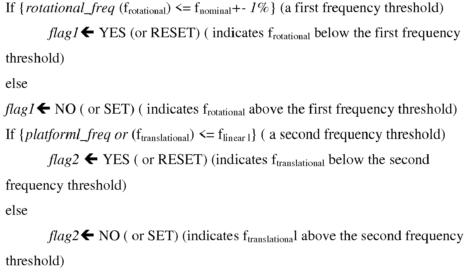
- Where, fnominal is dependent on prior knowledge of the rotational movement of the
target machine 106. Typically machines with rotating parts come with pre-defined RPM limit. The % tolerance depends on the application. During experimentation herein, for example, "1%" is acceptable tolerance. For example, the RPM of loaded and unloaded water pump may have variations more than 1%. The flinear, however has standardized values which marks safe/normal behavior of a machine of interest. For example, class 1 machines with linear motion above 4.5 mm/sec are be treated as CRITCAL which translates to 0.32 Hz for X-Band RADAR. This is as defined in the ISO 10816 standards. Calculations for the reference are provided below in conjunction with table 1.TABLE1: Class Critical vibration speed (mm/sec) as per ISO 10816 STANDARDS Observable Doppler frequency in Hz as per used X-Band Radar at 10.6 GHz 1 4.5 0.32 2 7.1 0.50 3 11.2 0.79 4 18.0 1.26 5 28 1.96 
target machine 106
v = velocity of the machine, f = radar transmitted frequency,
Wherein,
For class 1, - v = 4.5 mm/sec
- f= 10.6 GHz
- c =
3x 10^8 m/sec - Further, an alert notification is provided to an operator or end user if the estimated rotational frequency is above the first frequency threshold (first flag set) and the estimated translational frequency (ftranslational) is above the second frequency threshold (second flag set). An example decision table of the
decision module 214 is provided below in table 2:TABLE 2: flag1 flag2 Event reset reset Pass set No Alarm set set Alarm set set Alarm - The method 300 is now illustrated with an example through
FIGS. 4 and5 .FIG. 4 illustrates a standard Wide Band Frequency Spectrum (WBFM) used as reference spectrum for analyzing a frequency spectrum or power spectrum of the mD signal from thetarget machine 106 and captured by the RADAR. The WMFM spectrum depicted is the approximation using Bessel functions with fc = 390 Hz, fm = 6 Hz and β = 1. The standard WBFM spectrum is sourced from IEEE transactions tilted Micro-Doppler Effect in Radar: Phenomenon, Model, and Simulation Study "by VICTOR C. CHEN, 2006. - The
system 102 and the method 300 treats propeller rotation (rotational motion of rotational components of the target machine) along with a machine platform linear random movement (induced vibrations in rigid components of the target machine 106) jointly as a source of mD effect. The frequencies of the peaks of the power spectrum of the received mD signal will then contain information of a propeller rotation (froatational). Further, the sidebands or the modulation of (froatational) contain information of the linear movement of the platform (ftranslational), which are lateral induced vibrations into the rigid components due to the propeller rotation. - WBFM spectrums are approximated using Bessel functions, which is a function of β (modulation index) and (ftranslational), alternatively referred in the example as message-freq (fm) centered around a carrier frequency (fc ). Here, fc corresponds to propeller vibration (froatational).
- The method disclosed identifies a {β, fm} pair to find the linear motion (induced machine vibrations) of the machine platform.
-
FIG. 5 illustrates experimental results of analysis of the mD signal to determine induced machine vibrations of rotational components of an example machine into rigid components of the machine, in accordance with an embodiment of the present disclosure. -
FIG 5 depicts the analysis of the power spectrum. The steps of the analysis are provided below: - 1. Take power spectrum of the received RADAR signal.
- 2. Identify peak frequencies (∼5 dBC) in every window length of observation. (here 1 sec).
- 3. Jointly optimize to obtain the {β, fm} pair that gives maximum cross-correlation value between traces of the peaks of the received mD signal and the traces of a WBFM signal (constructed signal) generated by the {β, fm } pair, while -
- 4. Sweeping fm from 1 to 50 Hz
- 5. Sweeping β from 0.1 to 3 with step size 0.1
- 6. Appending zeros adaptively to keep the carrier peaks aligned of the two signals and measuring cross-correlation at zero lag.
- The written description describes the subject matter herein to enable any person skilled in the art to make and use the embodiments. The scope of the subject matter embodiments is defined by the claims and may include other modifications that occur to those skilled in the art. Such other modifications are intended to be within the scope of the claims if they have similar elements that do not differ from the literal language of the claims or if they include equivalent elements with insubstantial differences from the literal language of the claims.
- It is to be understood that the scope of the protection is extended to such a program and in addition to a computer-readable means having a message therein; such computer-readable storage means contain program-code means for implementation of one or more steps of the method, when the program runs on a server or mobile device or any suitable programmable device. The hardware device can be any kind of device which can be programmed including e.g. any kind of computer like a server or a personal computer, or the like, or any combination thereof. The device may also include means which could be e.g. hardware means like e.g. an application-specific integrated circuit (ASIC), a field-programmable gate array (FPGA), or a combination of hardware and software means, e.g. an ASIC and an FPGA, or at least one microprocessor and at least one memory with software modules located therein. Thus, the means can include both hardware means and software means. The method embodiments described herein could be implemented in hardware and software. The device may also include software means. Alternatively, the embodiments may be implemented on different hardware devices, e.g. using a plurality of CPUs.
- The embodiments herein can comprise hardware and software elements. The embodiments that are implemented in software include but are not limited to, firmware, resident software, microcode, etc. The functions performed by various modules described herein may be implemented in other modules or combinations of other modules. For the purposes of this description, a computer-usable or computer readable medium can be any apparatus that can comprise, store, communicate, propagate, or transport the program for use by or in connection with the instruction execution system, apparatus, or device.
- The illustrated steps are set out to explain the exemplary embodiments shown, and it should be anticipated that ongoing technological development will change the manner in which particular functions are performed. These examples are presented herein for purposes of illustration, and not limitation. Further, the boundaries of the functional building blocks have been arbitrarily defined herein for the convenience of the description. Alternative boundaries can be defined so long as the specified functions and relationships thereof are appropriately performed. Alternatives (including equivalents, extensions, variations, deviations, etc., of those described herein) will be apparent to persons skilled in the relevant art(s) based on the teachings contained herein. Such alternatives fall within the scope and spirit of the disclosed embodiments. Also, the words "comprising," "having," "containing," and "including," and other similar forms are intended to be equivalent in meaning and be open ended in that an item or items following any one of these words is not meant to be an exhaustive listing of such item or items, or meant to be limited to only the listed item or items. It must also be noted that as used herein and in the appended claims, the singular forms "a," "an," and "the" include plural references unless the context clearly dictates otherwise.
- Furthermore, one or more computer-readable storage media may be utilized in implementing embodiments consistent with the present disclosure. A computer-readable storage medium refers to any type of physical memory on which information or data readable by a processor may be stored. Thus, a computer-readable storage medium may store instructions for execution by one or more processors, including instructions for causing the processor(s) to perform steps or stages consistent with the embodiments described herein. The term "computer-readable medium" should be understood to include tangible items and exclude carrier waves and transient signals, i.e., be non-transitory. Examples include random access memory (RAM), read-only memory (ROM), volatile memory, nonvolatile memory, hard drives, CD ROMs, DVDs, flash drives, disks, and any other known physical storage media.
- It is intended that the disclosure and examples be considered as exemplary only, with a true scope and spirit of disclosed embodiments being indicated by the following claims.

Claims (9)
- A processor implemented method for monitoring machine health using RAdio Detection And Ranging (RADAR) based segregation for induced machine vibrations, the method comprising:receiving from a RADAR, by one or more hardware processors, a micro-Doppler (mD) signal corresponding to a predefined window length of observation, wherein a source of the mD signal captured by the RADAR is a target machine comprising a plurality of rotational components and a plurality of rigid components (302);preprocessing the received mD signal (304);obtaining a power spectrum of the preprocessed mD signal to determine a plurality of peak frequencies in the power spectrum with varying power levels, wherein a maximum peak frequency among the plurality of peak frequencies corresponding to a maximum power level represents a rotational frequency (frotational) associated with the plurality of rotational components of the target machine (306);determining a set of peak frequencies from the plurality of peak frequencies, wherein power level of the set of peak frequencies is below the maximum power level (308);varying a modulation index (β), for each peak frequency among the set of peak frequencies from a minimum modulation index (βmin) to a maximum modulation index (βmax) at regular predefined intervals (310);constructing a plurality of signals for each value of β varying from the minimum modulation index (β min) to the maximum modulation index (βmax) for each peak frequency from the set of peak frequencies (312);determining cross correlation between each constructed signal among the constructed plurality of signals and the preprocessed mD signal (314);identifying a constructed signal among the plurality of constructed signals that provides maximum value of cross correlation when each constructed signal is compared with the preprocessed mD signal (316); andestimating a frequency corresponding to the identified constructed signal as a translational frequency (ftranslational), wherein the translational frequency (ftranslational) corresponds to translational machine vibrations induced by the plurality of rotational components into the plurality of rigid components of the target machine (318).
- The method of claim 1, further comprising determining status (320) of a first flag associated with the rotational frequency (frotational) and a second flag associated with the translational frequency (ftranslational), wherein an alert notification is provided to an operator based on the status of the first flag and the status of the second flag if:the status of the first flag is set, which indicates that the rotational frequency (frotational) is above a first frequency threshold; orthe status of the second flag is set, which indicates that the estimated translational frequency (ftranslational) is above a second frequency threshold.
- The method of claim 1, wherein the preprocessing of the mD signal comprises:filtering the received mD signal with a band pass filter to select frequency band of the received mD signal to be analyzed and filter out noise present in the received mD signal; andperforming at least one of:interpolating the filtered mD signal to derive a higher
resolution mD signal; andcomputing double derivative of the interpolated mD signal to increase abrupt transitions in the filtered mD signal. - A system (102) for monitoring machine health using RAdio Detection And Ranging (RADAR) based segregation for induced machine vibrations, the system (102) comprising:a memory (202) storing instructions;one or more Input/Output (I/O) interfaces (206);and one or more hardware processors (204) coupled to the memory (202) via the one or more I/O interfaces (206), wherein the one or more hardware processors (204) are configured by the instructions to:receive from a RADAR (104) a micro-Doppler (mD) signal corresponding to a predefined window length of observation, wherein a source of the mD signal captured by the RADAR (104) is a target machine (106) comprising a plurality of rotational components and a plurality of rigid components;preprocess the received mD signal;obtain a power spectrum of the preprocessed mD signal to determine a plurality of peak frequencies in the power spectrum with varying power levels, wherein a maximum peak frequency among the plurality of peak frequencies corresponding to a maximum power level represents a rotational frequency (frotational) associated with the plurality of rotational components of the target machine (106);determine a set of peak frequencies from the plurality of peak frequencies, wherein power level of the set of peak frequencies is below the maximum power level;vary a modulation index (β), for each peak frequency among the set of peak frequencies from a minimum modulation index (β min) to a maximum modulation index (βmax) at regular predefined intervals;construct a plurality of signals for each value of β varying from the minimum modulation index (β min) to the maximum modulation index (βmax) for each peak frequency from the set of peak frequencies ;determine cross correlation between each constructed signal among the constructed plurality of signals and the preprocessed mD signal;identify a constructed signal among the plurality of constructed signals that provides maximum value of cross correlation when each constructed signal is compared with the preprocessed mD signal; andestimate a frequency corresponding to the identified constructed signal as a translational frequency (ftranslational), wherein the translational frequency (ftranslational) corresponds to translational machine vibrations induced by the plurality of rotational components into the plurality of rigid components of the target machine.
- The system (102) of claim 4, wherein the one or more hardware processors (204) are configured to determine status of a first flag associated with the rotational frequency (frotational) and a second flag associated with the translational frequency (ftranslational), wherein an alert notification is provided to an operator based on the status of the first flag and the status of the second flag if :the status of the first flag is set, which indicates that the rotational frequency (frotational) is above a first frequency threshold; orthe status of the second flag is set, which indicates that the estimated translational frequency (ftranslational) is above a second frequency threshold.
- The system (102) of claim 4, wherein the one or more hardware processors (204) are configured to preprocess of the mD signal by:filtering the received mD signal with a band pass filter to select frequency band of the received mD signal to be analyzed and filter out noise present in the received mD signal; andperforming at least one of:interpolating the filtered mD signal to derive a higher resolution mD signal; andcomputing double derivative of the interpolated mD signal to increase abrupt transitions in the filtered mD signal.
- One or more non-transitory machine readable information storage mediums comprising one or more instructions which when executed by one or more hardware processors causes a method for:receiving from a RAdio Detection And Ranging (RADAR) a micro-Doppler (mD) signal corresponding to a predefined window length of observation, wherein a source of the mD signal captured by the RADAR is a target machine comprising a plurality of rotational components and a plurality of rigid components;preprocessing the received mD signal;obtaining a power spectrum of the preprocessed mD signal to determine a plurality of peak frequencies in the power spectrum with varying power levels, wherein a maximum peak frequency among the plurality of peak frequencies corresponding to a maximum power level represents a rotational frequency (frotational) associated with the plurality of rotational components of the target machine;determining a set of peak frequencies from the plurality of peak frequencies, wherein power level of the set of peak frequencies is below the maximum power level;varying a modulation index (β), for each peak frequency among the set of peak frequencies from a minimum modulation index (βmin) to a maximum modulation index (βmax) at regular predefined intervals;constructing a plurality of signals for each value of β varying from the minimum modulation index (β min) to the maximum modulation index (βmax) for each peak frequency from the set of peak frequencies;determining cross correlation between each constructed signal among the constructed plurality of signals and the preprocessed mD signal;identifying a constructed signal among the plurality of constructed signals that provides maximum value of cross correlation when each constructed signal is compared with the preprocessed mD signal; andestimating a frequency corresponding to the identified constructed signal as a translational frequency (ftranslational), wherein the translational frequency (ftranslational) corresponds to translational machine vibrations induced by the plurality of rotational components into the plurality of rigid components of the target machine.
- The one or more non-transitory machine readable information storage mediums of claim7, further comprising determining status of a first flag associated with the rotational frequency (frotational) and a second flag associated with the translational frequency (ftranslational), wherein an alert notification is provided to an operator based on the status of the first flag and the status of the second flag if:the status of the first flag is set, which indicates that the rotational frequency (frotational) is above a first frequency threshold; orthe status of the second flag is set, which indicates that the estimated translational frequency (ftranslational) is above a second frequency threshold.
- The one or more non-transitory machine readable information storage mediums of claim 7, wherein the preprocessing of the mD signal comprises:filtering the received mD signal with a band pass filter to select frequency band of the received mD signal to be analyzed and filter out noise present in the received mD signal; andperforming at least one of:interpolating the filtered mD signal to derive a higher
resolution mD signal; andcomputing double derivative of the interpolated mD signal to increase abrupt transitions in the filtered mD signal.
Applications Claiming Priority (1)
| Application Number | Priority Date | Filing Date | Title |
|---|---|---|---|
| IN201821045986 | 2018-12-05 |
Publications (2)
| Publication Number | Publication Date |
|---|---|
| EP3663732A1 true EP3663732A1 (en) | 2020-06-10 |
| EP3663732B1 EP3663732B1 (en) | 2021-12-22 |
Family
ID=68766645
Family Applications (1)
| Application Number | Title | Priority Date | Filing Date |
|---|---|---|---|
| EP19213198.5A Active EP3663732B1 (en) | 2018-12-05 | 2019-12-03 | Method and system for monitoring machine condition using radar based segregation for induced machine vibrations |
Country Status (2)
| Country | Link |
|---|---|
| US (1) | US11402470B2 (en) |
| EP (1) | EP3663732B1 (en) |
Cited By (2)
| Publication number | Priority date | Publication date | Assignee | Title |
|---|---|---|---|---|
| CN112629838A (en) * | 2020-11-13 | 2021-04-09 | 三峡大学 | Wind turbine blade fault monitoring method |
| CN115753455A (en) * | 2022-11-03 | 2023-03-07 | 上海理工大学 | Electric drive system multidimensional load prediction method based on model and data hybrid driving |
Families Citing this family (5)
| Publication number | Priority date | Publication date | Assignee | Title |
|---|---|---|---|---|
| US11402470B2 (en) * | 2018-12-05 | 2022-08-02 | Tata Consultancy Services Limited | Method and system for monitoring machine health using radar based segregation for induced machine vibrations |
| CN112069651B (en) * | 2020-07-23 | 2024-04-09 | 西安空间无线电技术研究所 | A method for estimating the rotation axis of a spin-stabilized target based on ISAR imaging |
| CN111830483B (en) * | 2020-09-16 | 2020-12-22 | 福瑞泰克智能系统有限公司 | Method and device for determining target with inching effect, electronic equipment and storage medium |
| US12436232B2 (en) * | 2022-07-20 | 2025-10-07 | Applied Concepts, Inc. | Adaptive fan noise suppression for traffic radar systems |
| DE102022003178B3 (en) | 2022-08-30 | 2023-11-02 | Bundesrepublik Deutschland (Bundesamt für Ausrüstung, Informationstechnik und Nutzung der Bundeswehr) | Method for combating an enemy flying object |
Citations (5)
| Publication number | Priority date | Publication date | Assignee | Title |
|---|---|---|---|---|
| JPS5395678A (en) * | 1977-02-01 | 1978-08-22 | Toshiba Corp | Vibration detector of turbine blades |
| US20060048581A1 (en) * | 2003-01-23 | 2006-03-09 | Thomas Bosselmann | Method for determination of the stress on blades of a turbine machine during operation and corresponsing device for carrying out said method |
| CN106644030A (en) * | 2016-08-31 | 2017-05-10 | 上海交通大学 | Doppler radar-based non-contact type vibration measuring method |
| US9709671B1 (en) * | 2014-08-19 | 2017-07-18 | Dan Slater | Electrosound camera |
| US20180106889A1 (en) * | 2016-10-14 | 2018-04-19 | Lockheed Martin Corporation | System and method for radar based threat determination and classification |
Family Cites Families (10)
| Publication number | Priority date | Publication date | Assignee | Title |
|---|---|---|---|---|
| EP3186598B1 (en) * | 2014-12-02 | 2018-06-27 | Siemens Aktiengesellschaft | Monitoring of a device having a movable part |
| WO2019006473A1 (en) * | 2017-06-30 | 2019-01-03 | The Johns Hopkins University | Systems and method for action recognition using micro-doppler signatures and recurrent neural networks |
| US10705198B2 (en) * | 2018-03-27 | 2020-07-07 | Infineon Technologies Ag | System and method of monitoring an air flow using a millimeter-wave radar sensor |
| US10775482B2 (en) * | 2018-04-11 | 2020-09-15 | Infineon Technologies Ag | Human detection and identification in a setting using millimeter-wave radar |
| US10399393B1 (en) * | 2018-05-29 | 2019-09-03 | Infineon Technologies Ag | Radar sensor system for tire monitoring |
| US10845478B2 (en) * | 2018-09-07 | 2020-11-24 | GM Global Technology Operations LLC | Micro-doppler apparatus and method for trailer detection and tracking |
| US11402470B2 (en) * | 2018-12-05 | 2022-08-02 | Tata Consultancy Services Limited | Method and system for monitoring machine health using radar based segregation for induced machine vibrations |
| EP3716020B1 (en) * | 2019-03-29 | 2023-03-01 | Tata Consultancy Services Limited | Systems and methods for three dimensional (3d) reconstruction of human gestures from radar based measurements |
| EP3839811B1 (en) * | 2019-12-18 | 2024-03-13 | Tata Consultancy Services Limited | Systems and methods for shapelet decomposition based gesture recognition using radar |
| EP3913534B1 (en) * | 2020-05-22 | 2023-11-22 | Tata Consultancy Services Limited | System and method for real-time radar-based action recognition using spiking neural network(snn) |
-
2019
- 2019-12-03 US US16/702,430 patent/US11402470B2/en active Active
- 2019-12-03 EP EP19213198.5A patent/EP3663732B1/en active Active
Patent Citations (5)
| Publication number | Priority date | Publication date | Assignee | Title |
|---|---|---|---|---|
| JPS5395678A (en) * | 1977-02-01 | 1978-08-22 | Toshiba Corp | Vibration detector of turbine blades |
| US20060048581A1 (en) * | 2003-01-23 | 2006-03-09 | Thomas Bosselmann | Method for determination of the stress on blades of a turbine machine during operation and corresponsing device for carrying out said method |
| US9709671B1 (en) * | 2014-08-19 | 2017-07-18 | Dan Slater | Electrosound camera |
| CN106644030A (en) * | 2016-08-31 | 2017-05-10 | 上海交通大学 | Doppler radar-based non-contact type vibration measuring method |
| US20180106889A1 (en) * | 2016-10-14 | 2018-04-19 | Lockheed Martin Corporation | System and method for radar based threat determination and classification |
Non-Patent Citations (1)
| Title |
|---|
| HERSHBERGER JEREMY ET AL: "Non-contact rotating machine health status via dual-polarized radar", 2018 TEXAS SYMPOSIUM ON WIRELESS AND MICROWAVE CIRCUITS AND SYSTEMS (WMCS), IEEE, 5 April 2018 (2018-04-05), pages 1 - 6, XP033368686, DOI: 10.1109/WMCAS.2018.8400639 * |
Cited By (4)
| Publication number | Priority date | Publication date | Assignee | Title |
|---|---|---|---|---|
| CN112629838A (en) * | 2020-11-13 | 2021-04-09 | 三峡大学 | Wind turbine blade fault monitoring method |
| CN112629838B (en) * | 2020-11-13 | 2022-03-08 | 三峡大学 | Wind turbine blade fault monitoring method |
| CN115753455A (en) * | 2022-11-03 | 2023-03-07 | 上海理工大学 | Electric drive system multidimensional load prediction method based on model and data hybrid driving |
| CN115753455B (en) * | 2022-11-03 | 2024-02-13 | 上海理工大学 | Multi-dimensional load prediction method for electric drive system based on hybrid model and data drive |
Also Published As
| Publication number | Publication date |
|---|---|
| EP3663732B1 (en) | 2021-12-22 |
| US20200182967A1 (en) | 2020-06-11 |
| US11402470B2 (en) | 2022-08-02 |
Similar Documents
| Publication | Publication Date | Title |
|---|---|---|
| US11402470B2 (en) | Method and system for monitoring machine health using radar based segregation for induced machine vibrations | |
| Chegini et al. | New fault diagnosis approaches for detecting the bearing slight degradation | |
| US9239372B2 (en) | Extracting spectral features from a signal in a multiplicative and additive noise environment | |
| Wang et al. | A morphogram with the optimal selection of parameters used in morphological analysis for enhancing the ability in bearing fault diagnosis | |
| US20210117538A1 (en) | Information processing apparatus, information processing method, and computer readable medium | |
| EP3193156A1 (en) | Rotary machine malfunction detection device, rotary machine malfunction detection method, and rotary machine | |
| CN110057583A (en) | A kind of bearing fault recognition methods, device and computer equipment | |
| EP3561464B1 (en) | Unobtrusive and automated detection of frequencies of spatially located distinct parts of a machine | |
| US20160371228A1 (en) | System and method for detecting outliers in real-time for a univariate time-series signal | |
| Khan et al. | Rotational speed invariant fault diagnosis in bearings using vibration signal imaging and local binary patterns | |
| CN116224274A (en) | Low-slow and small target detection method, device and equipment based on dynamic threshold factor | |
| AU2019201494B2 (en) | Non-contact material inspection | |
| EP3790022B1 (en) | Method and system for heart rate estimation of a user | |
| RU2726270C1 (en) | Method for monitoring the technical state of mechanisms | |
| US11543325B2 (en) | Monitoring machine vibration | |
| Dhakar et al. | Fault identification of reciprocating air compressor using signal processing techniques and kurtosis index-based bubble cloud analysis | |
| EP3337157A1 (en) | System and method for detecting vibrations of a machine using a low frames per second (fps) camera | |
| US10480932B2 (en) | Automated computation of a dimension of a moving platform | |
| Muhammad et al. | Frequency spectrum-based diagnosis of structural gear faults using dual-sensor acoustic and vibration signals | |
| EP4481430A1 (en) | Non-contact method and system for inspection and detection of water saturated regions in rockmass | |
| Liang et al. | A new approach to diagnose rolling bearing faults based on AFD | |
| Gang et al. | Real-time indoor positioning system based on background training model using IR-UWB radar | |
| CN111294411A (en) | Monitoring system | |
| Nadkarni et al. | Monitoring Local Faults in Aerospace-grade Gearboxes and Bearings Using an IoT Sensing Platform | |
| US12072260B2 (en) | Device for monitoring an equipment |
Legal Events
| Date | Code | Title | Description |
|---|---|---|---|
| PUAI | Public reference made under article 153(3) epc to a published international application that has entered the european phase |
Free format text: ORIGINAL CODE: 0009012 |
|
| STAA | Information on the status of an ep patent application or granted ep patent |
Free format text: STATUS: THE APPLICATION HAS BEEN PUBLISHED |
|
| AK | Designated contracting states |
Kind code of ref document: A1 Designated state(s): AL AT BE BG CH CY CZ DE DK EE ES FI FR GB GR HR HU IE IS IT LI LT LU LV MC MK MT NL NO PL PT RO RS SE SI SK SM TR |
|
| AX | Request for extension of the european patent |
Extension state: BA ME |
|
| STAA | Information on the status of an ep patent application or granted ep patent |
Free format text: STATUS: REQUEST FOR EXAMINATION WAS MADE |
|
| 17P | Request for examination filed |
Effective date: 20201210 |
|
| RBV | Designated contracting states (corrected) |
Designated state(s): AL AT BE BG CH CY CZ DE DK EE ES FI FR GB GR HR HU IE IS IT LI LT LU LV MC MK MT NL NO PL PT RO RS SE SI SK SM TR |
|
| GRAP | Despatch of communication of intention to grant a patent |
Free format text: ORIGINAL CODE: EPIDOSNIGR1 |
|
| STAA | Information on the status of an ep patent application or granted ep patent |
Free format text: STATUS: GRANT OF PATENT IS INTENDED |
|
| INTG | Intention to grant announced |
Effective date: 20210629 |
|
| GRAS | Grant fee paid |
Free format text: ORIGINAL CODE: EPIDOSNIGR3 |
|
| GRAA | (expected) grant |
Free format text: ORIGINAL CODE: 0009210 |
|
| STAA | Information on the status of an ep patent application or granted ep patent |
Free format text: STATUS: THE PATENT HAS BEEN GRANTED |
|
| AK | Designated contracting states |
Kind code of ref document: B1 Designated state(s): AL AT BE BG CH CY CZ DE DK EE ES FI FR GB GR HR HU IE IS IT LI LT LU LV MC MK MT NL NO PL PT RO RS SE SI SK SM TR |
|
| REG | Reference to a national code |
Ref country code: GB Ref legal event code: FG4D |
|
| REG | Reference to a national code |
Ref country code: CH Ref legal event code: EP |
|
| REG | Reference to a national code |
Ref country code: DE Ref legal event code: R096 Ref document number: 602019010260 Country of ref document: DE |
|
| REG | Reference to a national code |
Ref country code: AT Ref legal event code: REF Ref document number: 1457360 Country of ref document: AT Kind code of ref document: T Effective date: 20220115 |
|
| REG | Reference to a national code |
Ref country code: IE Ref legal event code: FG4D |
|
| REG | Reference to a national code |
Ref country code: NL Ref legal event code: FP |
|
| REG | Reference to a national code |
Ref country code: LT Ref legal event code: MG9D |
|
| PG25 | Lapsed in a contracting state [announced via postgrant information from national office to epo] |
Ref country code: RS Free format text: LAPSE BECAUSE OF FAILURE TO SUBMIT A TRANSLATION OF THE DESCRIPTION OR TO PAY THE FEE WITHIN THE PRESCRIBED TIME-LIMIT Effective date: 20211222 Ref country code: LT Free format text: LAPSE BECAUSE OF FAILURE TO SUBMIT A TRANSLATION OF THE DESCRIPTION OR TO PAY THE FEE WITHIN THE PRESCRIBED TIME-LIMIT Effective date: 20211222 Ref country code: FI Free format text: LAPSE BECAUSE OF FAILURE TO SUBMIT A TRANSLATION OF THE DESCRIPTION OR TO PAY THE FEE WITHIN THE PRESCRIBED TIME-LIMIT Effective date: 20211222 Ref country code: BG Free format text: LAPSE BECAUSE OF FAILURE TO SUBMIT A TRANSLATION OF THE DESCRIPTION OR TO PAY THE FEE WITHIN THE PRESCRIBED TIME-LIMIT Effective date: 20220322 |
|
| REG | Reference to a national code |
Ref country code: AT Ref legal event code: MK05 Ref document number: 1457360 Country of ref document: AT Kind code of ref document: T Effective date: 20211222 |
|
| PG25 | Lapsed in a contracting state [announced via postgrant information from national office to epo] |
Ref country code: SE Free format text: LAPSE BECAUSE OF FAILURE TO SUBMIT A TRANSLATION OF THE DESCRIPTION OR TO PAY THE FEE WITHIN THE PRESCRIBED TIME-LIMIT Effective date: 20211222 Ref country code: NO Free format text: LAPSE BECAUSE OF FAILURE TO SUBMIT A TRANSLATION OF THE DESCRIPTION OR TO PAY THE FEE WITHIN THE PRESCRIBED TIME-LIMIT Effective date: 20220322 Ref country code: LV Free format text: LAPSE BECAUSE OF FAILURE TO SUBMIT A TRANSLATION OF THE DESCRIPTION OR TO PAY THE FEE WITHIN THE PRESCRIBED TIME-LIMIT Effective date: 20211222 Ref country code: HR Free format text: LAPSE BECAUSE OF FAILURE TO SUBMIT A TRANSLATION OF THE DESCRIPTION OR TO PAY THE FEE WITHIN THE PRESCRIBED TIME-LIMIT Effective date: 20211222 Ref country code: GR Free format text: LAPSE BECAUSE OF FAILURE TO SUBMIT A TRANSLATION OF THE DESCRIPTION OR TO PAY THE FEE WITHIN THE PRESCRIBED TIME-LIMIT Effective date: 20220323 |
|
| PG25 | Lapsed in a contracting state [announced via postgrant information from national office to epo] |
Ref country code: SM Free format text: LAPSE BECAUSE OF FAILURE TO SUBMIT A TRANSLATION OF THE DESCRIPTION OR TO PAY THE FEE WITHIN THE PRESCRIBED TIME-LIMIT Effective date: 20211222 Ref country code: SK Free format text: LAPSE BECAUSE OF FAILURE TO SUBMIT A TRANSLATION OF THE DESCRIPTION OR TO PAY THE FEE WITHIN THE PRESCRIBED TIME-LIMIT Effective date: 20211222 Ref country code: RO Free format text: LAPSE BECAUSE OF FAILURE TO SUBMIT A TRANSLATION OF THE DESCRIPTION OR TO PAY THE FEE WITHIN THE PRESCRIBED TIME-LIMIT Effective date: 20211222 Ref country code: PT Free format text: LAPSE BECAUSE OF FAILURE TO SUBMIT A TRANSLATION OF THE DESCRIPTION OR TO PAY THE FEE WITHIN THE PRESCRIBED TIME-LIMIT Effective date: 20220422 Ref country code: ES Free format text: LAPSE BECAUSE OF FAILURE TO SUBMIT A TRANSLATION OF THE DESCRIPTION OR TO PAY THE FEE WITHIN THE PRESCRIBED TIME-LIMIT Effective date: 20211222 Ref country code: EE Free format text: LAPSE BECAUSE OF FAILURE TO SUBMIT A TRANSLATION OF THE DESCRIPTION OR TO PAY THE FEE WITHIN THE PRESCRIBED TIME-LIMIT Effective date: 20211222 Ref country code: CZ Free format text: LAPSE BECAUSE OF FAILURE TO SUBMIT A TRANSLATION OF THE DESCRIPTION OR TO PAY THE FEE WITHIN THE PRESCRIBED TIME-LIMIT Effective date: 20211222 |
|
| PG25 | Lapsed in a contracting state [announced via postgrant information from national office to epo] |
Ref country code: PL Free format text: LAPSE BECAUSE OF FAILURE TO SUBMIT A TRANSLATION OF THE DESCRIPTION OR TO PAY THE FEE WITHIN THE PRESCRIBED TIME-LIMIT Effective date: 20211222 Ref country code: AT Free format text: LAPSE BECAUSE OF FAILURE TO SUBMIT A TRANSLATION OF THE DESCRIPTION OR TO PAY THE FEE WITHIN THE PRESCRIBED TIME-LIMIT Effective date: 20211222 |
|
| REG | Reference to a national code |
Ref country code: DE Ref legal event code: R097 Ref document number: 602019010260 Country of ref document: DE |
|
| PG25 | Lapsed in a contracting state [announced via postgrant information from national office to epo] |
Ref country code: IS Free format text: LAPSE BECAUSE OF FAILURE TO SUBMIT A TRANSLATION OF THE DESCRIPTION OR TO PAY THE FEE WITHIN THE PRESCRIBED TIME-LIMIT Effective date: 20220422 |
|
| PLBE | No opposition filed within time limit |
Free format text: ORIGINAL CODE: 0009261 |
|
| STAA | Information on the status of an ep patent application or granted ep patent |
Free format text: STATUS: NO OPPOSITION FILED WITHIN TIME LIMIT |
|
| PG25 | Lapsed in a contracting state [announced via postgrant information from national office to epo] |
Ref country code: DK Free format text: LAPSE BECAUSE OF FAILURE TO SUBMIT A TRANSLATION OF THE DESCRIPTION OR TO PAY THE FEE WITHIN THE PRESCRIBED TIME-LIMIT Effective date: 20211222 Ref country code: AL Free format text: LAPSE BECAUSE OF FAILURE TO SUBMIT A TRANSLATION OF THE DESCRIPTION OR TO PAY THE FEE WITHIN THE PRESCRIBED TIME-LIMIT Effective date: 20211222 |
|
| 26N | No opposition filed |
Effective date: 20220923 |
|
| PG25 | Lapsed in a contracting state [announced via postgrant information from national office to epo] |
Ref country code: SI Free format text: LAPSE BECAUSE OF FAILURE TO SUBMIT A TRANSLATION OF THE DESCRIPTION OR TO PAY THE FEE WITHIN THE PRESCRIBED TIME-LIMIT Effective date: 20211222 |
|
| PG25 | Lapsed in a contracting state [announced via postgrant information from national office to epo] |
Ref country code: IT Free format text: LAPSE BECAUSE OF FAILURE TO SUBMIT A TRANSLATION OF THE DESCRIPTION OR TO PAY THE FEE WITHIN THE PRESCRIBED TIME-LIMIT Effective date: 20211222 |
|
| P01 | Opt-out of the competence of the unified patent court (upc) registered |
Effective date: 20230526 |
|
| REG | Reference to a national code |
Ref country code: BE Ref legal event code: MM Effective date: 20221231 |
|
| PG25 | Lapsed in a contracting state [announced via postgrant information from national office to epo] |
Ref country code: LU Free format text: LAPSE BECAUSE OF NON-PAYMENT OF DUE FEES Effective date: 20221203 |
|
| PG25 | Lapsed in a contracting state [announced via postgrant information from national office to epo] |
Ref country code: IE Free format text: LAPSE BECAUSE OF NON-PAYMENT OF DUE FEES Effective date: 20221203 |
|
| PG25 | Lapsed in a contracting state [announced via postgrant information from national office to epo] |
Ref country code: BE Free format text: LAPSE BECAUSE OF NON-PAYMENT OF DUE FEES Effective date: 20221231 |
|
| PG25 | Lapsed in a contracting state [announced via postgrant information from national office to epo] |
Ref country code: HU Free format text: LAPSE BECAUSE OF FAILURE TO SUBMIT A TRANSLATION OF THE DESCRIPTION OR TO PAY THE FEE WITHIN THE PRESCRIBED TIME-LIMIT; INVALID AB INITIO Effective date: 20191203 |
|
| PG25 | Lapsed in a contracting state [announced via postgrant information from national office to epo] |
Ref country code: CY Free format text: LAPSE BECAUSE OF FAILURE TO SUBMIT A TRANSLATION OF THE DESCRIPTION OR TO PAY THE FEE WITHIN THE PRESCRIBED TIME-LIMIT Effective date: 20211222 |
|
| PG25 | Lapsed in a contracting state [announced via postgrant information from national office to epo] |
Ref country code: MK Free format text: LAPSE BECAUSE OF FAILURE TO SUBMIT A TRANSLATION OF THE DESCRIPTION OR TO PAY THE FEE WITHIN THE PRESCRIBED TIME-LIMIT Effective date: 20211222 |
|
| PG25 | Lapsed in a contracting state [announced via postgrant information from national office to epo] |
Ref country code: MC Free format text: LAPSE BECAUSE OF FAILURE TO SUBMIT A TRANSLATION OF THE DESCRIPTION OR TO PAY THE FEE WITHIN THE PRESCRIBED TIME-LIMIT Effective date: 20211222 |
|
| PG25 | Lapsed in a contracting state [announced via postgrant information from national office to epo] |
Ref country code: TR Free format text: LAPSE BECAUSE OF FAILURE TO SUBMIT A TRANSLATION OF THE DESCRIPTION OR TO PAY THE FEE WITHIN THE PRESCRIBED TIME-LIMIT Effective date: 20211222 Ref country code: MC Free format text: LAPSE BECAUSE OF FAILURE TO SUBMIT A TRANSLATION OF THE DESCRIPTION OR TO PAY THE FEE WITHIN THE PRESCRIBED TIME-LIMIT Effective date: 20211222 |
|
| PG25 | Lapsed in a contracting state [announced via postgrant information from national office to epo] |
Ref country code: MT Free format text: LAPSE BECAUSE OF FAILURE TO SUBMIT A TRANSLATION OF THE DESCRIPTION OR TO PAY THE FEE WITHIN THE PRESCRIBED TIME-LIMIT Effective date: 20211222 |
|
| REG | Reference to a national code |
Ref country code: CH Ref legal event code: U11 Free format text: ST27 STATUS EVENT CODE: U-0-0-U10-U11 (AS PROVIDED BY THE NATIONAL OFFICE) Effective date: 20260101 |
|
| PGFP | Annual fee paid to national office [announced via postgrant information from national office to epo] |
Ref country code: GB Payment date: 20251223 Year of fee payment: 7 |
|
| PGFP | Annual fee paid to national office [announced via postgrant information from national office to epo] |
Ref country code: FR Payment date: 20251223 Year of fee payment: 7 Ref country code: NL Payment date: 20251222 Year of fee payment: 7 |
|
| PGFP | Annual fee paid to national office [announced via postgrant information from national office to epo] |
Ref country code: DE Payment date: 20251229 Year of fee payment: 7 |
|
| PGFP | Annual fee paid to national office [announced via postgrant information from national office to epo] |
Ref country code: CH Payment date: 20260101 Year of fee payment: 7 |