EP3663710A1 - Detector assembly, detector, and laser ranging system - Google Patents
Detector assembly, detector, and laser ranging system Download PDFInfo
- Publication number
- EP3663710A1 EP3663710A1 EP18841977.4A EP18841977A EP3663710A1 EP 3663710 A1 EP3663710 A1 EP 3663710A1 EP 18841977 A EP18841977 A EP 18841977A EP 3663710 A1 EP3663710 A1 EP 3663710A1
- Authority
- EP
- European Patent Office
- Prior art keywords
- laser
- receiving unit
- detector assembly
- level
- laser receiving
- Prior art date
- Legal status (The legal status is an assumption and is not a legal conclusion. Google has not performed a legal analysis and makes no representation as to the accuracy of the status listed.)
- Withdrawn
Links
Images

Classifications
-
- G—PHYSICS
- G01—MEASURING; TESTING
- G01S—RADIO DIRECTION-FINDING; RADIO NAVIGATION; DETERMINING DISTANCE OR VELOCITY BY USE OF RADIO WAVES; LOCATING OR PRESENCE-DETECTING BY USE OF THE REFLECTION OR RERADIATION OF RADIO WAVES; ANALOGOUS ARRANGEMENTS USING OTHER WAVES
- G01S11/00—Systems for determining distance or velocity not using reflection or reradiation
- G01S11/12—Systems for determining distance or velocity not using reflection or reradiation using electromagnetic waves other than radio waves
-
- G—PHYSICS
- G01—MEASURING; TESTING
- G01C—MEASURING DISTANCES, LEVELS OR BEARINGS; SURVEYING; NAVIGATION; GYROSCOPIC INSTRUMENTS; PHOTOGRAMMETRY OR VIDEOGRAMMETRY
- G01C15/00—Surveying instruments or accessories not provided for in groups G01C1/00 - G01C13/00
- G01C15/002—Active optical surveying means
- G01C15/004—Reference lines, planes or sectors
- G01C15/006—Detectors therefor
-
- G—PHYSICS
- G01—MEASURING; TESTING
- G01S—RADIO DIRECTION-FINDING; RADIO NAVIGATION; DETERMINING DISTANCE OR VELOCITY BY USE OF RADIO WAVES; LOCATING OR PRESENCE-DETECTING BY USE OF THE REFLECTION OR RERADIATION OF RADIO WAVES; ANALOGOUS ARRANGEMENTS USING OTHER WAVES
- G01S17/00—Systems using the reflection or reradiation of electromagnetic waves other than radio waves, e.g. lidar systems
- G01S17/02—Systems using the reflection of electromagnetic waves other than radio waves
- G01S17/06—Systems determining position data of a target
- G01S17/08—Systems determining position data of a target for measuring distance only
-
- G—PHYSICS
- G01—MEASURING; TESTING
- G01S—RADIO DIRECTION-FINDING; RADIO NAVIGATION; DETERMINING DISTANCE OR VELOCITY BY USE OF RADIO WAVES; LOCATING OR PRESENCE-DETECTING BY USE OF THE REFLECTION OR RERADIATION OF RADIO WAVES; ANALOGOUS ARRANGEMENTS USING OTHER WAVES
- G01S7/00—Details of systems according to groups G01S13/00, G01S15/00, G01S17/00
- G01S7/48—Details of systems according to groups G01S13/00, G01S15/00, G01S17/00 of systems according to group G01S17/00
- G01S7/481—Constructional features, e.g. arrangements of optical elements
- G01S7/4816—Constructional features, e.g. arrangements of optical elements of receivers alone
Definitions
- the present disclosure relates to distance measuring and positioning field, more particularly, to a detector assembly for use with a laser level, a detector including the previously described detector assembly, and a laser ranging system.
- Chinese Published Patent Application No. CN101206113A discloses a rangefinder and a ranging method thereof.
- the rangefinder according to the published patent application uses a rotating light source to provide a light beam with a predetermined rotation speed, and then uses a receiver to detect the time difference when the light beam is rotated from the first position to the second position of the receiver, and calculates the distance between the receiver and the rotating light source based on the detected time difference and the distance between the first position and the second position of the receiver.
- the rangefinder and the ranging method described above can conveniently implement the ranging function in the laser level, thereby improving the construction convenience for the engineers.
- FIG. 1 illustrates a schematic diagram of a rangefinder based on the published patent application described above.
- a rangefinder 10 is constructed on a single-axis rotating laser level 11 and a receiver 12 thereof.
- the single-axis rotating laser level 11 can not only provide an automatically leveled rotating laser beam 13 to project a horizontal reference line on the construction wall, but also assist engineers to measure the distance needed for construction marking.
- the receiver 12 may further include a remote control circuit 16 for remote controller the operation of the single-axis rotating laser level 11, such as the rotation speed, which can be used as a remote controller for remotely controlling the single-axis rotating laser level 11.
- a remote control circuit 16 for remote controller the operation of the single-axis rotating laser level 11, such as the rotation speed, which can be used as a remote controller for remotely controlling the single-axis rotating laser level 11.
- the receiver 12 in addition to using the a rotating light source composed of the single-axis rotating laser level 11 to provide the laser beam 13 at a predetermined rotation speed, the receiver 12 can also be used to detect the time difference when the laser beam is rotated from a first position 14 to a second position 15 of the receiver. As such, the distance between the receiver 12 and the single-axis rotating laser level 11 can be calculated based on the time difference and the distance between the first position 14 and the second position 15.
- a laser receiving device includes an independent first receiving circuit and a second receiving circuit.
- the first receiving circuit and the second receiving circuit can respectively include a conversion circuit connected to a light sensor to convert the current signal into a voltage signal; an amplifier circuit connected to the conversion circuit to amplify the voltage signal; and a comparator connected to the amplifier circuit to compare the amplified voltage signal with a reference level, and output an electric signal representing the detected light beam.
- each laser detector device needs to include at least two sets of light sensors, conversion circuits, amplifier circuits, and comparators. As such, the production cost of the laser receiving device is high, and the structure of the laser receiving device is complicated. In addition, since such a detector assembly includes only the laser receiver 12 in one direction, the detector assembly cannot guarantee the three distances from the light beam to the first position 14, from the light beam to the second position 15, and between the first position and the second position to form an isosceles triangle. As such, the calculated distance between a light beam emitting position and the detector assembly is inaccurate, and the error is uncontrollable.
- the present disclosure provides a detector assembly for use with a laser level.
- the detector assembly includes a first laser receiving unit configured to receive laser emitted from a first laser emitting module of the laser level and a second laser receiving unit configured to be arranged to be substantially perpendicular to the first laser receiving unit.
- the second laser receiving unit also includes a first portion for receiving laser emitted from a second laser emitting module of the laser level and a second portion for receiving the laser emitted from the second laser emitting module of the laser level, where the first portion and the second portion are separated by a first distance.
- the detector assembly When in use, in accordance with the present disclosure, the detector assembly is arranged vertically. At this moment, the first laser receiving unit of the detector assembly is also arranged vertically, that is, arranged to be perpendicular to a horizontal surface. Accordingly, with the laser level capable of emitting a horizontal laser, and through a certain adjustment process, the horizontal laser surface emitted from the laser level is ensured to be in the middle between the first portion for receiving the laser emitted from the second laser emitting module of the laser level and the second portion for receiving the laser emitted from the second laser emitting module of the laser level, so that the distances from the first portion of the detector assembly for receiving the laser emitted from the second laser emitting module of the laser level and the second portion of the detector assembly for receiving the laser emitted from the second laser emitting module of the laser level to the first laser emitting module of the laser level can be ensured to be the same.
- the distances from the first portion of the detector assembly for receiving the laser emitted from the second laser emitting module of the laser level and the second portion of the detector assembly for receiving the laser emitted from the second laser emitting module of the laser level to the second laser emitting module of the laser level can be consequentially ensured to be the same.
- a precise distance between the laser level and the detector assembly can be determined according to a trigonometric function relationship.
- the detector assembly may also include a signal processing module, which is configured to process the laser received by the first laser receiving unit and/or the laser received by the second laser receiving unit.
- the first portion and the second portion of the second laser receiving unit have the same lengths and are arranged parallel to each other.
- the distances from the first portion and the second portion of the second laser receiving unit to the first laser receiving unit are the same.
- the first laser receiving unit and/or the second laser receiving unit are configured as photoelectric sensors.
- the second laser receiving unit is configured as a light guiding element.
- the first portion of the light guiding element is configured to receive light beam and transmit the light beam to a first target position
- the second portion of the light guiding element is configured to receive the light beam and transmit the light beam to the first target position.
- the detector assembly may also include light sensing elements, which are arranged at the first target position.
- the detector assembly may also include an amplifier circuit, which is configured to be coupled between the first laser receiving unit and/or the second laser receiving unit and the signal processing module.
- the amplifier circuit is also configured to amplify the electrical signal converted from the optical signal from the first laser receiving unit and/or the second laser receiving unit and output to the signal processing module.
- the detector assembly may also include a filter circuit, which is configured to be coupled with the first laser receiving unit and/or the second laser receiving unit and the signal processing module.
- the filter circuit is also configured to filter the electrical signal converted from the optical signal from the first laser receiving unit and/or the second laser receiving unit and output to the signal processing module.
- a detector that can be used with the laser level.
- the detector includes the detector assembly provided in accordance with the first aspect of the present disclosure.
- a laser ranging system includes the detector provided in accordance with the second aspect of the present disclosure.
- the straight-line distance between the laser level and the detector assembly can be measured accurately.
- arranged horizontally and arranged vertically refer to the arrangement of light sensing elements included in the laser receiving device.
- arranged vertically means that light sensing elements, e.g., the light sensing stripes, in the laser receiving device are arranged to be substantially perpendicular to a horizontal plane
- arranged horizontally means that light sensing elements, e.g., e.g., the light sensing stripes, in the laser receiving device are arranged substantially on the same horizontal plane.
- FIG. 2 to FIG. 5 new structures of detector assemblies are provided and shown in FIG. 2 to FIG. 5 .
- the detector assemblies and each embodiment of the detector assemblies will be described in relation to FIG. 2 to FIG. 5 .
- FIG. 2 to FIG. 5 are merely exemplary and not restrictive, are only used to exemplarily show possible structural forms of the detector assemblies according to the present disclosure, and are not intended to exhaust all possible structural forms of the detector assemblies according to the present disclosure.
- Those skilled in the art can make modifications to these embodiments based on this technology without exceeding the concept of the present disclosure, and the modified variants are still within the scope of the present disclosure.
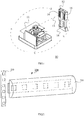
- a detector assembly 200 includes a first laser receiving unit 210, and the first laser receiving unit 210 is configured to receive laser emitted from a first laser emitting module (not shown in the Figure) of a laser level (not shown in the Figure).
- the detector assembly 200 also includes a second laser receiving unit 220.
- the second laser receiving unit 220 is configured to be substantially perpendicular to the first laser receiving unit 210 and includes a first portion for receiving the laser emitted from a second laser emitting module of the laser level and a second portion for receiving the laser emitted from a second laser emitting module of the laser level, where the first portion and the second portion are separated by a first distance.
- FIG. 3 shows a schematic diagram of a detector assembly 300 according to another embodiment of the present disclosure.
- the detector assembly 300 includes a first laser receiving unit 310, and the first laser receiving unit 310 is configured to receive laser emitted from a first laser emitting module (not shown in the figure) of a laser level (not shown in the figure).
- the detector assembly 300 includes a second laser receiving unit 320.
- the second laser receiving unit 320 is configured to be substantially perpendicular to the first laser receiving unit 310 and includes a first portion for receiving the laser emitted from the second laser emitting module of the laser level and a second portion for receiving the laser emitted from the second laser emitting module of the laser level, where the first portion and the second portion are separated by a first distance.
- FIG. 4 shows a schematic diagram of a detector assembly 400 according to another embodiment of the present disclosure.
- a detector assembly 400 includes a first laser receiving unit 410, and the first laser receiving unit 410 is configured to receive laser emitted from a first laser emitting module (not shown in the figure) of a laser level (not shown in the figure).
- the detector assembly 400 includes a second laser receiving unit 420.
- the second laser receiving unit 420 is configured to be substantially perpendicular to the first laser receiving unit 410 and includes a first portion for receiving the laser emitted from the second laser emitting module of the laser level and a second portion for receiving the laser emitted from the second laser emitting module of the laser level.
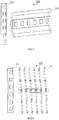
- the second laser receiving unit 420 includes six optical fibers, and each optical fiber has optical fiber light guiding heads at an upper side and a lower side of the direction shown in the figure. When a light beam passes by, the light beam is received and transmitted to the corresponding light sensing elements.
- the six optical fibers shown here are only exemplary and not restrictive.
- the optical detector assembly may include more than or fewer than six optical fibers.
- FIG. 5 shows a schematic diagram of a detector assembly 400 according to another embodiment of the present disclosure.
- a detector assembly 500 includes a first laser receiving unit 510, and the first laser receiving unit 510 is configured to receive laser emitted from a first laser emitting module (not shown in the figure) of a laser level (not shown in the figure).
- the detector assembly 500 includes a second laser receiving unit 520.
- the second laser receiving unit 520 is configured to be substantially perpendicular to the first laser receiving unit 510 and includes a first portion for receiving the laser emitted from the second laser emitting module of the laser level and a second portion for receiving the laser emitted from the second laser emitting module of the laser level. The first portion and the second portion are separated by a first distance.
- the detector assemblies also include timer modules.
- the timer modules are configured to calculate the time differences between the times when each of the respective first portions and each of the respective second portions of the second laser receiving units 220, 320, 420, and 520 sense the laser. By knowing the laser scan speed of the laser emitting module of the laser level and the time difference when the laser passes the first portion and the second portion, the distance between the laser level and the detector assembly can be calculated according to the first distance.
- the first portion and the second portion are configured correspondingly at the two positions of the second laser receiving units 220 and 320.
- the second laser receiving unit 220 includes the first portion for receiving and transmitting the light beam to the light sensing elements (elements with dashed lines shown in the figure) and the second portion for receiving and transmitting the light beam to the light sensing elements.
- the first portion for receiving and transmitting the light beam to the light sensing elements and the second portion for receiving and transmitting the light beam to the light sensing elements form a pair of measuring points. In each measurement, the laser beam will pass each part of a pair of measuring points in sequence.
- the first portion and the second portion are arranged at the two sides of the second laser receiving unit 220.
- the first portion and the second portion at two sides of the second laser receiving unit 220 are merely exemplary not restrictive and the first portion and the second portion may also be arranged at other positions.
- the first portion may be configured to receive and transmit the light beam to the light sensing elements at first
- the second portion may be configured to receive and transmit the light beam to the light sensing elements at last. In the embodiment shown in FIG.
- the portion that receives and transmits the light beam to the light sensing elements at first may be the first portion for receiving and transmitting the light beam to the light sensing elements 210, at the upper side, and the portion that receives and transmits the light beam to the light sensing elements at last may be the second portion for receiving and transmitting the light beam to the light sensing elements, for example, at the bottom side.
- the measurement can be performed at the longest measurement distance i.e., at the longest measurement time, to reduce error and improve measurement precision.
- the detector assembly 200 may be arranged vertically.
- the first laser receiving unit 210 contained in the detector assembly 200 is also arranged vertically, that is, arranged to be perpendicular to the horizontal surface.
- the horizontal laser emitted from the laser level is ensured to be in the middle between the first portion for receiving the laser emitted from the second laser emitting module of the laser level and the second portion for receiving the laser emitted from the second laser emitting module of the laser level, so that the distances from the first portion of the detector assembly 200 for receiving the laser emitted from the second laser emitting module of the laser level and the second portion of the detector assembly 200 for receiving the laser emitted from the second laser emitting module of the laser level to the first laser emitting module of the laser level can be ensured to be the same.
- the distances from the first portion of the detector assembly 200 for receiving the laser emitted from the second laser emitting module of the laser level and the second portion of the detector assembly 200 for receiving the laser emitted from the second laser emitting module of the laser level to the second laser emitting module of the laser level can be consequentially ensured to be the same.
- the precise distance between the laser level and the detector assembly 200 can be determined according to a trigonometric function relationship. How to calculate the precise distance between the laser level and the detector assembly 200 according to the trigonometric function relationship known to those skilled in the art, so it will not be repeated herewith.
- the detector assembly 200 also includes a signal processing module (not shown in the figure), which is configured to process the laser received by the first laser receiving unit 210 and the laser received by the second laser receiving unit 220.
- the signal processing module can perform operations such as analog to digital conversions, etc., to electric signals generated according to the laser received by the first laser receiving unit 210 and the laser received by the second laser receiving unit 220, so that a transferability and anti-inference ability of the electrical signals are improved.
- the first portion and second portion of the second laser receiving unit 220 have the same lengths and are arranged parallel to each other.
- the first portion and the second portion are located at two sides of the semi-cylindrical second laser receiving unit 220 (e.g., a semi-cylindrical lens), respectively.
- the first portion and the second portion of the second laser receiving unit 220 have the same lengths and are arranged parallel to each other.
- the first portion and the second portion are located at two sides of the spherical mirror-shaped second laser receiving unit 320 (e.g., a cylindrical mirror).
- the first portion and the second portion of the second laser receiving unit 320 have the same lengths and are arranged parallel to each other.
- the second laser receiving unit 420 constitutes a plurality of optical fibers arranged parallel to each other, and the optical fibers are parallel to each other and have the same lengths.
- the second laser receiving unit 520 constitutes two silicon photocell modules which are arranged parallel to each other and have the same lengths.
- the first laser receiving unit and/or the second laser receiving unit may also be configured as photoelectric sensors, which can be made of avalanche photo diodes (APD), charge-coupled elements (CCD), other solar cells, or other materials that can sense laser.
- the solar cells are preferably the silicon photovoltaic modules.
- the distances from the first portions and the second portions of the second laser receiving units 220, 320, and 520 to the first laser receiving units may be same.
- the distances from the second laser receiving units 220, 320, and 520 to the end sides of the first laser receiving units 210, 310, and 510 are the same, and when in use, the first laser receiving units 210, 310, and 510 are arranged vertically.
- the second laser receiving units 220, 320, and 420 are configured as light guiding elements.
- the first portion of the light guiding element is configured for receiving light beam and transmitting the light beam to the first target position
- the second portion of the light guiding element is configured for receiving light beam and transmitting the light beam to the first target position.
- the second laser receiving units 220, 320, and 420 are configured as the light guiding elements.
- the detector assemblies 200, 300, and 400 also include light sensing elements, which are located at the first target position.
- the second laser receiving unit 520 is configured as two separate silicon photovoltaic modules.
- the elements used as the second laser receiving units 220 and 320 in the concept of the present disclosure can be configured as, for example, spherical mirrors, free-form surface mirrors, aspheric mirrors, light guiding columns, light guiding surfaces, plane mirrors, optical fibers, or reflecting mirrors.
- the second laser receiving units 220, 320, and 420 are configured as light guiding elements, compared to the second laser receiving unit 520 shown in FIG. 5 , only a set of light sensing elements need to be configured, so that the structure of the detector assembly is simplified, and the cost of the detector assembly is accordingly reduced.
- the detector assembly also includes an amplifier circuit, and the amplifier circuit is configured to be coupled between the first laser receiving unit and/or the second laser receiving unit and the signal processing module.
- the amplifier circuit is also configured to amplify and output the electrical signals converted from the optical signals from the first laser receiving unit and/or the second laser receiving unit to the signal processing module.
- the detector assembly also includes a filter circuit, and the filter circuit is configured to be coupled between the first laser receiving unit and/or the second laser receiving unit and the signal processing module.
- the filter circuit is also configured to filter and output the electrical signal converted from the optical signal from the first laser receiving unit and/or the second laser receiving unit to the signal processing module.
- a detector for use with the laser level.
- the detector includes the detector assembly in accordance with the first aspect of the present disclosure.
- a laser ranging system is provided, and the laser ranging system includes the detector in accordance with the second aspect of the present disclosure.
- embodiments according to the present disclosure use the detector assembly and the corresponding laser ranging system to accurately measure the straight-line distance between the laser level and the detector assembly.
Landscapes
- Physics & Mathematics (AREA)
- Engineering & Computer Science (AREA)
- General Physics & Mathematics (AREA)
- Radar, Positioning & Navigation (AREA)
- Remote Sensing (AREA)
- Electromagnetism (AREA)
- Computer Networks & Wireless Communication (AREA)
- Optical Radar Systems And Details Thereof (AREA)
- Measurement Of Optical Distance (AREA)
Abstract
Description
- The present disclosure relates to distance measuring and positioning field, more particularly, to a detector assembly for use with a laser level, a detector including the previously described detector assembly, and a laser ranging system.
- In conventional technology, Chinese Published Patent Application No.
CN101206113A discloses a rangefinder and a ranging method thereof. The rangefinder according to the published patent application uses a rotating light source to provide a light beam with a predetermined rotation speed, and then uses a receiver to detect the time difference when the light beam is rotated from the first position to the second position of the receiver, and calculates the distance between the receiver and the rotating light source based on the detected time difference and the distance between the first position and the second position of the receiver. The rangefinder and the ranging method described above can conveniently implement the ranging function in the laser level, thereby improving the construction convenience for the engineers. - More specifically, reference may be made to
FIG. 1 , which illustrates a schematic diagram of a rangefinder based on the published patent application described above. As shown inFIG. 1 , in order to improve the usefulness of construction convenience for the engineers, arangefinder 10 is constructed on a single-axis rotatinglaser level 11 and areceiver 12 thereof. As such, the single-axis rotatinglaser level 11 can not only provide an automatically leveled rotatinglaser beam 13 to project a horizontal reference line on the construction wall, but also assist engineers to measure the distance needed for construction marking. In particular, thereceiver 12 may further include aremote control circuit 16 for remote controller the operation of the single-axis rotatinglaser level 11, such as the rotation speed, which can be used as a remote controller for remotely controlling the single-axis rotatinglaser level 11. InFIG. 1 , in addition to using the a rotating light source composed of the single-axis rotatinglaser level 11 to provide thelaser beam 13 at a predetermined rotation speed, thereceiver 12 can also be used to detect the time difference when the laser beam is rotated from afirst position 14 to asecond position 15 of the receiver. As such, the distance between thereceiver 12 and the single-axis rotatinglaser level 11 can be calculated based on the time difference and the distance between thefirst position 14 and thesecond position 15. - It should be apparent from the above description that a laser receiving device includes an independent first receiving circuit and a second receiving circuit. Further, the first receiving circuit and the second receiving circuit can respectively include a conversion circuit connected to a light sensor to convert the current signal into a voltage signal; an amplifier circuit connected to the conversion circuit to amplify the voltage signal; and a comparator connected to the amplifier circuit to compare the amplified voltage signal with a reference level, and output an electric signal representing the detected light beam.
- Therefore, each laser detector device needs to include at least two sets of light sensors, conversion circuits, amplifier circuits, and comparators. As such, the production cost of the laser receiving device is high, and the structure of the laser receiving device is complicated. In addition, since such a detector assembly includes only the
laser receiver 12 in one direction, the detector assembly cannot guarantee the three distances from the light beam to thefirst position 14, from the light beam to thesecond position 15, and between the first position and the second position to form an isosceles triangle. As such, the calculated distance between a light beam emitting position and the detector assembly is inaccurate, and the error is uncontrollable. - In view of the technical problem described above, that is, the inevitable technical problem of inaccurate ranging in prior art, the present disclosure provides a detector assembly for use with a laser level. The detector assembly includes a first laser receiving unit configured to receive laser emitted from a first laser emitting module of the laser level and a second laser receiving unit configured to be arranged to be substantially perpendicular to the first laser receiving unit. The second laser receiving unit also includes a first portion for receiving laser emitted from a second laser emitting module of the laser level and a second portion for receiving the laser emitted from the second laser emitting module of the laser level, where the first portion and the second portion are separated by a first distance.
- When in use, in accordance with the present disclosure, the detector assembly is arranged vertically. At this moment, the first laser receiving unit of the detector assembly is also arranged vertically, that is, arranged to be perpendicular to a horizontal surface. Accordingly, with the laser level capable of emitting a horizontal laser, and through a certain adjustment process, the horizontal laser surface emitted from the laser level is ensured to be in the middle between the first portion for receiving the laser emitted from the second laser emitting module of the laser level and the second portion for receiving the laser emitted from the second laser emitting module of the laser level, so that the distances from the first portion of the detector assembly for receiving the laser emitted from the second laser emitting module of the laser level and the second portion of the detector assembly for receiving the laser emitted from the second laser emitting module of the laser level to the first laser emitting module of the laser level can be ensured to be the same. Through a corresponding setting, the distances from the first portion of the detector assembly for receiving the laser emitted from the second laser emitting module of the laser level and the second portion of the detector assembly for receiving the laser emitted from the second laser emitting module of the laser level to the second laser emitting module of the laser level can be consequentially ensured to be the same.
- Accordingly, through the scanning/rotation speed of the second laser emitting module of the laser level, the first distance between the first portion for receiving the laser emitted from the second laser emitting module of the laser level and the second portion for receiving the laser emitted from the second laser emitting module of the laser level, and the time difference between the corresponding times when the laser passes the first portion for receiving the laser emitted from the second laser emitting module of the laser level and the second portion for receiving the laser emitted from the second laser emitting module of the laser level, a precise distance between the laser level and the detector assembly can be determined according to a trigonometric function relationship.
- In accordance with an embodiment of the present disclosure, the detector assembly may also include a signal processing module, which is configured to process the laser received by the first laser receiving unit and/or the laser received by the second laser receiving unit.
- In accordance with an embodiment of the present disclosure, the first portion and the second portion of the second laser receiving unit have the same lengths and are arranged parallel to each other.
- In accordance with an embodiment of the present disclosure, the distances from the first portion and the second portion of the second laser receiving unit to the first laser receiving unit are the same.
- In accordance with an embodiment of the present disclosure, the first laser receiving unit and/or the second laser receiving unit are configured as photoelectric sensors.
- In accordance with an embodiment of the present disclosure, the second laser receiving unit is configured as a light guiding element. The first portion of the light guiding element is configured to receive light beam and transmit the light beam to a first target position, and the second portion of the light guiding element is configured to receive the light beam and transmit the light beam to the first target position.
- In accordance with an embodiment of the present disclosure the detector assembly may also include light sensing elements, which are arranged at the first target position.
- In accordance with an embodiment of the present disclosure, the detector assembly may also include an amplifier circuit, which is configured to be coupled between the first laser receiving unit and/or the second laser receiving unit and the signal processing module. The amplifier circuit is also configured to amplify the electrical signal converted from the optical signal from the first laser receiving unit and/or the second laser receiving unit and output to the signal processing module.
- In accordance with an embodiment of the present disclosure, the detector assembly may also include a filter circuit, which is configured to be coupled with the first laser receiving unit and/or the second laser receiving unit and the signal processing module. The filter circuit is also configured to filter the electrical signal converted from the optical signal from the first laser receiving unit and/or the second laser receiving unit and output to the signal processing module.
- In addition, in accordance with a second aspect of the present disclosure, a detector that can be used with the laser level is provided. The detector includes the detector assembly provided in accordance with the first aspect of the present disclosure.
- In accordance with a third aspect of the present disclosure, a laser ranging system is provided. The laser ranging system includes the detector provided in accordance with the second aspect of the present disclosure.
- As mentioned above, with the detector assembly and the corresponding laser ranging system provided in accordance with the present disclosure, the straight-line distance between the laser level and the detector assembly can be measured accurately.
- Embodiments are illustrated and set forth with reference to the accompanying figures. These figures are for purpose of clarifying basic principles, thus only illustrating the aspects necessary for understanding the basic principles. These figures are not drawn to scale. The same reference labels have been repeated among the figures to indicate analogous features.
-
FIG. 1 is a schematic diagram of arangefinder 10 according to a prior technology. -
FIG. 2 is a schematic diagram of adetector assembly 200 according to an embodiment of the present disclosure. -
FIG. 3 is a schematic diagram of adetector assembly 300 according to another embodiment of the present disclosure. -
FIG. 4 is a schematic diagram of a detector assembly 400 according to another embodiment of the present disclosure. -
FIG. 5 is a schematic diagram of adetector assembly 500 according to another embodiment of the present disclosure. - Other characteristics, features, advantages and benefits of the present disclosure will be more apparent from the detailed description below in connection with the accompanying figures.
- In the following detailed description of preferred embodiments, reference will be made to the accompanying figures which constitute a part of the present disclosure. The accompanying figures illustrate specific embodiments capable of implementing the present disclosure by way of example. The exemplary embodiments are not intended to exhaust all embodiments in accordance with the present disclosure. It can be understood that other embodiments may be utilized, or structural or logical modifications may be made without departing the scope of the present disclosure. Therefore, the following detailed description is not limiting, and the scope of the present disclosure is defined by the appended claims.
- The applicant of this application wishes to make clear that the terms "arranged horizontally" and "arranged vertically" mentioned in the context of the application both refer to the arrangement of light sensing elements included in the laser receiving device. The term "arranged vertically" means that light sensing elements, e.g., the light sensing stripes, in the laser receiving device are arranged to be substantially perpendicular to a horizontal plane, and the term "arranged horizontally" means that light sensing elements, e.g., e.g., the light sensing stripes, in the laser receiving device are arranged substantially on the same horizontal plane.
- In view of the technical problem that the laser receiving device in
FIG. 1 cannot control the error when performing the distance measurement between the laser emitting device and the laser receiving device to perform accurate distance measurement, new structures of detector assemblies are provided and shown inFIG. 2 to FIG. 5 . In accordance with the present disclosure, the detector assemblies and each embodiment of the detector assemblies will be described in relation toFIG. 2 to FIG. 5 . Those of skill in the art would understand that the embodiments ofFIG. 2 to FIG. 5 are merely exemplary and not restrictive, are only used to exemplarily show possible structural forms of the detector assemblies according to the present disclosure, and are not intended to exhaust all possible structural forms of the detector assemblies according to the present disclosure. Those skilled in the art can make modifications to these embodiments based on this technology without exceeding the concept of the present disclosure, and the modified variants are still within the scope of the present disclosure. - As shown in
FIG. 2 , in accordance with the present disclosure, adetector assembly 200 includes a firstlaser receiving unit 210, and the firstlaser receiving unit 210 is configured to receive laser emitted from a first laser emitting module (not shown in the Figure) of a laser level (not shown in the Figure). In accordance with the present disclosure, thedetector assembly 200 also includes a secondlaser receiving unit 220. The secondlaser receiving unit 220 is configured to be substantially perpendicular to the firstlaser receiving unit 210 and includes a first portion for receiving the laser emitted from a second laser emitting module of the laser level and a second portion for receiving the laser emitted from a second laser emitting module of the laser level, where the first portion and the second portion are separated by a first distance. -
FIG. 3 shows a schematic diagram of adetector assembly 300 according to another embodiment of the present disclosure. As shown inFIG. 3 , in accordance with the present disclosure, thedetector assembly 300 includes a firstlaser receiving unit 310, and the firstlaser receiving unit 310 is configured to receive laser emitted from a first laser emitting module (not shown in the figure) of a laser level (not shown in the figure). In accordance with the present disclosure, thedetector assembly 300 includes a secondlaser receiving unit 320. The secondlaser receiving unit 320 is configured to be substantially perpendicular to the firstlaser receiving unit 310 and includes a first portion for receiving the laser emitted from the second laser emitting module of the laser level and a second portion for receiving the laser emitted from the second laser emitting module of the laser level, where the first portion and the second portion are separated by a first distance. -
FIG. 4 shows a schematic diagram of a detector assembly 400 according to another embodiment of the present disclosure. As shown inFIG. 4 , in accordance with the present disclosure, a detector assembly 400 includes a firstlaser receiving unit 410, and the firstlaser receiving unit 410 is configured to receive laser emitted from a first laser emitting module (not shown in the figure) of a laser level (not shown in the figure). In accordance with the present disclosure, the detector assembly 400 includes a secondlaser receiving unit 420. The secondlaser receiving unit 420 is configured to be substantially perpendicular to the firstlaser receiving unit 410 and includes a first portion for receiving the laser emitted from the second laser emitting module of the laser level and a second portion for receiving the laser emitted from the second laser emitting module of the laser level. The first portion and the second portion are separated by a first distance. In the embodiment shown inFIG. 4 , the secondlaser receiving unit 420 includes six optical fibers, and each optical fiber has optical fiber light guiding heads at an upper side and a lower side of the direction shown in the figure. When a light beam passes by, the light beam is received and transmitted to the corresponding light sensing elements. Those skilled in the art would understand that the six optical fibers shown here are only exemplary and not restrictive. In accordance with the present disclosure, the optical detector assembly may include more than or fewer than six optical fibers. -
FIG. 5 shows a schematic diagram of a detector assembly 400 according to another embodiment of the present disclosure. As shown inFIG. 5 , in accordance with the present disclosure, adetector assembly 500 includes a firstlaser receiving unit 510, and the firstlaser receiving unit 510 is configured to receive laser emitted from a first laser emitting module (not shown in the figure) of a laser level (not shown in the figure). In accordance with the present disclosure, thedetector assembly 500 includes a secondlaser receiving unit 520. The secondlaser receiving unit 520 is configured to be substantially perpendicular to the firstlaser receiving unit 510 and includes a first portion for receiving the laser emitted from the second laser emitting module of the laser level and a second portion for receiving the laser emitted from the second laser emitting module of the laser level. The first portion and the second portion are separated by a first distance. - In one embodiment of the present disclosure, the detector assemblies also include timer modules. The timer modules are configured to calculate the time differences between the times when each of the respective first portions and each of the respective second portions of the second
laser receiving units - The first portion and the second portion are configured correspondingly at the two positions of the second
laser receiving units FIG. 2 , the secondlaser receiving unit 220 includes the first portion for receiving and transmitting the light beam to the light sensing elements (elements with dashed lines shown in the figure) and the second portion for receiving and transmitting the light beam to the light sensing elements. In the embodiment, the first portion for receiving and transmitting the light beam to the light sensing elements and the second portion for receiving and transmitting the light beam to the light sensing elements form a pair of measuring points. In each measurement, the laser beam will pass each part of a pair of measuring points in sequence. In the embodiment shown inFIG. 2 , the first portion and the second portion are arranged at the two sides of the secondlaser receiving unit 220. - The first portion and the second portion at two sides of the second
laser receiving unit 220 are merely exemplary not restrictive and the first portion and the second portion may also be arranged at other positions. For example, the first portion may be configured to receive and transmit the light beam to the light sensing elements at first, and the second portion may be configured to receive and transmit the light beam to the light sensing elements at last. In the embodiment shown inFIG. 2 , the portion that receives and transmits the light beam to the light sensing elements at first may be the first portion for receiving and transmitting the light beam to thelight sensing elements 210, at the upper side, and the portion that receives and transmits the light beam to the light sensing elements at last may be the second portion for receiving and transmitting the light beam to the light sensing elements, for example, at the bottom side. Applying the method in the embodiment, the measurement can be performed at the longest measurement distance i.e., at the longest measurement time, to reduce error and improve measurement precision. - Accordingly, when in use, in accordance with the present disclosure, the
detector assembly 200 may be arranged vertically. At this moment, the firstlaser receiving unit 210 contained in thedetector assembly 200 is also arranged vertically, that is, arranged to be perpendicular to the horizontal surface. Accordingly, with the laser level capable of emitting horizontal laser, and through a certain adjustment process, the horizontal laser emitted from the laser level is ensured to be in the middle between the first portion for receiving the laser emitted from the second laser emitting module of the laser level and the second portion for receiving the laser emitted from the second laser emitting module of the laser level, so that the distances from the first portion of thedetector assembly 200 for receiving the laser emitted from the second laser emitting module of the laser level and the second portion of thedetector assembly 200 for receiving the laser emitted from the second laser emitting module of the laser level to the first laser emitting module of the laser level can be ensured to be the same. Through a corresponding setting, the distances from the first portion of thedetector assembly 200 for receiving the laser emitted from the second laser emitting module of the laser level and the second portion of thedetector assembly 200 for receiving the laser emitted from the second laser emitting module of the laser level to the second laser emitting module of the laser level can be consequentially ensured to be the same. Accordingly, given the scanning or rotation speed of the second laser emitting module of the laser level, the first distance between the first portion for receiving the laser emitted from the second laser emitting module of the laser level and the second portion for receiving the laser emitted from the second laser emitting module of the laser level, and the time difference between the corresponding times when the laser passes the first portion for receiving the laser emitted from the second laser emitting module of the laser level and the second portion for receiving the laser emitted from the second laser emitting module of the laser level, the precise distance between the laser level and thedetector assembly 200 can be determined according to a trigonometric function relationship. How to calculate the precise distance between the laser level and thedetector assembly 200 according to the trigonometric function relationship known to those skilled in the art, so it will not be repeated herewith. - In accordance with an embodiment of the present disclosure, the
detector assembly 200 also includes a signal processing module (not shown in the figure), which is configured to process the laser received by the firstlaser receiving unit 210 and the laser received by the secondlaser receiving unit 220. For example, the signal processing module can perform operations such as analog to digital conversions, etc., to electric signals generated according to the laser received by the firstlaser receiving unit 210 and the laser received by the secondlaser receiving unit 220, so that a transferability and anti-inference ability of the electrical signals are improved. - In accordance with an embodiment of the present disclosure, the first portion and second portion of the second
laser receiving unit 220 have the same lengths and are arranged parallel to each other. - Specifically, in the embodiment shown in
FIG. 2 , the first portion and the second portion are located at two sides of the semi-cylindrical second laser receiving unit 220 (e.g., a semi-cylindrical lens), respectively. Correspondingly, the first portion and the second portion of the secondlaser receiving unit 220 have the same lengths and are arranged parallel to each other. In the embodiment shown inFIG. 3 , the first portion and the second portion are located at two sides of the spherical mirror-shaped second laser receiving unit 320 (e.g., a cylindrical mirror). Correspondingly, the first portion and the second portion of the secondlaser receiving unit 320 have the same lengths and are arranged parallel to each other. In the embodiment shown inFIG. 4 , the secondlaser receiving unit 420 constitutes a plurality of optical fibers arranged parallel to each other, and the optical fibers are parallel to each other and have the same lengths. Correspondingly, in the embodiment shown inFIG. 5 , the secondlaser receiving unit 520 constitutes two silicon photocell modules which are arranged parallel to each other and have the same lengths. Those skilled in the art would understand that the first laser receiving unit and/or the second laser receiving unit may also be configured as photoelectric sensors, which can be made of avalanche photo diodes (APD), charge-coupled elements (CCD), other solar cells, or other materials that can sense laser. The solar cells are preferably the silicon photovoltaic modules. - In accordance with an embodiment of the present disclosure, the distances from the first portions and the second portions of the second
laser receiving units FIG. 2 ,FIG. 3 , andFIG. 5 , the distances from the secondlaser receiving units laser receiving units laser receiving units - In accordance with an embodiment of the present disclosure, the second
laser receiving units FIG. 2 to FIG. 4 , the secondlaser receiving units FIG. 2 to FIG. 4 , thedetector assemblies FIG. 5 , the secondlaser receiving unit 520 is configured as two separate silicon photovoltaic modules. - In the above embodiments, the elements used as the second
laser receiving units - When the second
laser receiving units laser receiving unit 520 shown inFIG. 5 , only a set of light sensing elements need to be configured, so that the structure of the detector assembly is simplified, and the cost of the detector assembly is accordingly reduced. - To improve the processing accuracy of the electrical signals, in accordance with an embodiment of the present disclosure, the detector assembly also includes an amplifier circuit, and the amplifier circuit is configured to be coupled between the first laser receiving unit and/or the second laser receiving unit and the signal processing module. The amplifier circuit is also configured to amplify and output the electrical signals converted from the optical signals from the first laser receiving unit and/or the second laser receiving unit to the signal processing module.
- To improve the anti-interference ability of the electrical signal in the detector assembly according to the present disclosure, the detector assembly also includes a filter circuit, and the filter circuit is configured to be coupled between the first laser receiving unit and/or the second laser receiving unit and the signal processing module. The filter circuit is also configured to filter and output the electrical signal converted from the optical signal from the first laser receiving unit and/or the second laser receiving unit to the signal processing module.
- In addition, in accordance with a second aspect of the present disclosure, a detector is provided for use with the laser level. The detector includes the detector assembly in accordance with the first aspect of the present disclosure.
- In accordance with a third aspect of the present disclosure, a laser ranging system is provided, and the laser ranging system includes the detector in accordance with the second aspect of the present disclosure.
- As discussed above, embodiments according to the present disclosure use the detector assembly and the corresponding laser ranging system to accurately measure the straight-line distance between the laser level and the detector assembly.
- Those skilled in the art should understand that, various variations and modifications may be made to the various embodiments disclosed above without departing from the nature of the invention. Thus, the scope of the invention should be defined by the appended claims.
- Although different exemplary embodiments have been described, it would be apparent to those skilled in the art that, different changes and modifications may be made which may implement some of the advantages of the invention without departing the spirit and scope of the invention. For those skilled in the art, other components performing the same function may be properly substituted. It should be noted that, here the features explained with reference to specific figures may be combined with the features of other figures, even if in cases where it is not explicitly mentioned. Further, methods of the invention may be implemented in all software implementations using proper processor instructions or in mixed implementations which obtain the same result utilizing the combination of hardware logics and software logics. Such modifications to the scheme in accordance with the invention are intended to be covered by the appended claims.
Claims (10)
- A detector assembly for use with a laser level, comprising:a first laser receiving unit configured to receive laser emitted from a first laser emitting module of the laser level; anda second laser receiving unit configured to be arranged perpendicular to the first laser receiving unit, the second laser receiving unit including a first portion for receiving laser emitted from a second laser emitting module of the laser level, and a second portion for receiving the laser emitted from the second laser emitting module of the laser level, wherein the first portion and the second portion are apart by a first distance.
- The detector assembly of claim 1, further comprising a signal processing module, wherein the signal processing module is configured to process the laser received by the first laser receiving unit and/or the laser received by the second laser receiving unit.
- The detector assembly of claim 1 or 2, wherein the first portion and the second portion of the second laser receiving unit have same lengths and are parallel to each other.
- The detector assembly of claim 1 or 2, wherein the first laser receiving unit and/or the second laser receiving unit are configured as photovoltaic sensors.
- The detector assembly of claim 1 or 2, wherein the second laser receiving unit is configured as a light guiding element, a first portion of the light guiding element is configured to receive light beam and transmit the light beam to a first target position, and a second portion of the light guiding element is configured to receive the light beam and transmit the light beam to the first target position.
- The detector assembly of claim 5, further comprising light sensing elements, wherein the light sensing elements are arranged at the first target position.
- The detector assembly of claim 2, further comprising:
an amplifier circuit, configured to be coupled between the first laser receiving unit and/or the second laser receiving unit and the signal processing module and to amplify and output electrical signals converted from optical signals from the first laser receiving unit and/or the second laser receiving unit to the signal processing module. - The detector assembly of claim 2, further comprising:
a filter circuit, configured to be coupled between the first laser receiving unit and/or the second laser receiving unit and the signal processing module and to filter and output electrical signals converted from optical signals from the first laser receiving unit and/or the second laser receiving unit to the signal processing module. - A detector for use with a laser level comprising any detector assembly of claim 1 to 8.
- A laser ranging system comprising the detector of claim 9.
Applications Claiming Priority (2)
| Application Number | Priority Date | Filing Date | Title |
|---|---|---|---|
| CN201710661768.7A CN107290739B (en) | 2017-08-04 | 2017-08-04 | Detector assembly, detector and laser ranging system |
| PCT/CN2018/096945 WO2019024730A1 (en) | 2017-08-04 | 2018-07-25 | Detector assembly, detector, and laser ranging system |
Publications (2)
| Publication Number | Publication Date |
|---|---|
| EP3663710A1 true EP3663710A1 (en) | 2020-06-10 |
| EP3663710A4 EP3663710A4 (en) | 2021-05-19 |
Family
ID=60105252
Family Applications (1)
| Application Number | Title | Priority Date | Filing Date |
|---|---|---|---|
| EP18841977.4A Withdrawn EP3663710A4 (en) | 2017-08-04 | 2018-07-25 | LASER DETECTOR, DETECTOR AND TELEMETRY SYSTEM KIT |
Country Status (4)
| Country | Link |
|---|---|
| US (1) | US11119202B2 (en) |
| EP (1) | EP3663710A4 (en) |
| CN (1) | CN107290739B (en) |
| WO (1) | WO2019024730A1 (en) |
Families Citing this family (10)
| Publication number | Priority date | Publication date | Assignee | Title |
|---|---|---|---|---|
| US12055414B2 (en) | 2015-02-16 | 2024-08-06 | Northwest Instrument Inc. | Ranging system and ranging method |
| CN107290049B (en) * | 2017-08-04 | 2019-01-15 | 上海诺司纬光电仪器有限公司 | Optical detection components, detectors and laser ranging systems |
| CN107218920B (en) * | 2017-08-04 | 2020-07-10 | 美国西北仪器公司 | Distance measuring method and distance measuring system |
| CN107290739B (en) * | 2017-08-04 | 2020-06-16 | 美国西北仪器公司 | Detector assembly, detector and laser ranging system |
| CN108760044B (en) * | 2018-05-24 | 2021-02-02 | 罗华 | High-precision long-distance laser receiving sensing positioning method and system |
| CN116391107A (en) | 2020-12-01 | 2023-07-04 | 米沃奇电动工具公司 | Laser level interface and controls |
| EP4323722A4 (en) | 2021-04-12 | 2025-03-05 | Milwaukee Electric Tool Corporation | LASER LEVEL SYSTEM WITH AUTOMATIC DETECTOR ALIGNMENT |
| WO2022221141A1 (en) * | 2021-04-12 | 2022-10-20 | Milwaukee Electric Tool Corporation | Laser level system with automatic detector alignment |
| CN113280788B (en) * | 2021-06-01 | 2022-10-11 | 中国科学院西北生态环境资源研究院 | Roadbed settlement monitoring device and system |
| CN222234115U (en) | 2021-12-29 | 2024-12-24 | 米沃奇电动工具公司 | Laser generating device |
Family Cites Families (22)
| Publication number | Priority date | Publication date | Assignee | Title |
|---|---|---|---|---|
| US5189484A (en) * | 1991-08-13 | 1993-02-23 | Koschmann Eric C | Laser beam detector for grade elevation measurement |
| CN1207595C (en) * | 2000-05-31 | 2005-06-22 | 古河电气工业株式会社 | Semiconductor laser module |
| AU2001279795A1 (en) * | 2000-08-01 | 2002-02-13 | Mirko Essling | Measuring device and measuring method for determining distance and/or position |
| DE10123756A1 (en) * | 2001-05-16 | 2002-12-05 | Bosch Gmbh Robert | Method and device for making a laser beam position visible |
| US20040101020A1 (en) * | 2002-11-26 | 2004-05-27 | Photodigm, Inc. | Packaging and passive alignment of light source to single mode fiber using microlens and precision ferrule |
| CN101206113A (en) * | 2006-12-20 | 2008-06-25 | 方础光电科技股份有限公司 | Distance measuring instrument and distance measuring method thereof |
| US20080241843A1 (en) * | 2006-12-21 | 2008-10-02 | Stanford University | Single-cell analysis systems, methods of counting molecules in a single-cell, cylindrical fluorescence detection systems |
| JP4927182B2 (en) * | 2009-06-22 | 2012-05-09 | 株式会社 ニコンビジョン | Laser distance meter |
| US8522446B1 (en) * | 2009-12-08 | 2013-09-03 | Karl E. Staudt | Level assembly |
| US9400170B2 (en) * | 2010-04-21 | 2016-07-26 | Faro Technologies, Inc. | Automatic measurement of dimensional data within an acceptance region by a laser tracker |
| US8537376B2 (en) * | 2011-04-15 | 2013-09-17 | Faro Technologies, Inc. | Enhanced position detector in laser tracker |
| CN103075963B (en) * | 2013-01-09 | 2015-09-16 | 广州创特技术有限公司 | A kind of indoor locating system and method |
| CN103308038B (en) * | 2013-06-30 | 2015-07-15 | 湖南农业大学 | Laser receiving device and laser spot center identification method |
| CN203489883U (en) * | 2013-09-30 | 2014-03-19 | 常州维尔曼光电仪器有限公司 | Leveler |
| US20150377604A1 (en) * | 2014-06-27 | 2015-12-31 | Faro Technologies, Inc. | Zoom camera assembly having integrated illuminator |
| JP6597150B2 (en) * | 2015-10-09 | 2019-10-30 | 富士通株式会社 | Distance measuring device, distance measuring method, distance measuring program, and table creation method |
| CN205300605U (en) * | 2016-01-12 | 2016-06-08 | 苏州福田激光精密仪器有限公司 | Laser swinger NULL device |
| CN206193236U (en) * | 2016-11-09 | 2017-05-24 | 莱赛激光科技股份有限公司 | Biax gradient laser swinger , laser swinger subassembly |
| CN106886027B (en) * | 2017-02-24 | 2020-04-10 | 上海诺司纬光电仪器有限公司 | Laser positioning device and laser positioning method |
| CN107218920B (en) | 2017-08-04 | 2020-07-10 | 美国西北仪器公司 | Distance measuring method and distance measuring system |
| CN207074263U (en) * | 2017-08-04 | 2018-03-06 | 美国西北仪器公司 | Detector components, detectors and laser ranging systems |
| CN107290739B (en) | 2017-08-04 | 2020-06-16 | 美国西北仪器公司 | Detector assembly, detector and laser ranging system |
-
2017
- 2017-08-04 CN CN201710661768.7A patent/CN107290739B/en active Active
-
2018
- 2018-07-25 WO PCT/CN2018/096945 patent/WO2019024730A1/en not_active Ceased
- 2018-07-25 EP EP18841977.4A patent/EP3663710A4/en not_active Withdrawn
- 2018-07-25 US US16/636,508 patent/US11119202B2/en active Active
Also Published As
| Publication number | Publication date |
|---|---|
| CN107290739B (en) | 2020-06-16 |
| WO2019024730A1 (en) | 2019-02-07 |
| EP3663710A4 (en) | 2021-05-19 |
| US11119202B2 (en) | 2021-09-14 |
| CN107290739A (en) | 2017-10-24 |
| US20200249336A1 (en) | 2020-08-06 |
Similar Documents
| Publication | Publication Date | Title |
|---|---|---|
| US11119202B2 (en) | Detector assembly, detector, and laser ranging system | |
| EP3663711B1 (en) | Distance measurement method and distance measurement system | |
| AU2019268121B2 (en) | LiDAR scanner calibration | |
| WO2019104679A1 (en) | Power adjustment method and laser measurement device | |
| GB2178165A (en) | Optical monitoring method and apparatus | |
| US20180128904A1 (en) | Lidar scanner with optical amplification | |
| US11598851B2 (en) | Optical detecting assembly, detector and laser ranging system | |
| US4277169A (en) | Device for simultaneously performing alignment and sighting operations | |
| CN111964699A (en) | High-precision encoder based on image recognition and implementation method thereof | |
| CN101240520A (en) | Railway line parameter photoelectric testing device used for tamping vehicle and detection method thereof | |
| CN207074263U (en) | Detector components, detectors and laser ranging systems | |
| CN207081481U (en) | Optical detection components, detectors and laser ranging systems | |
| JP2019032325A (en) | Displacement detecting device and method for measuring displacement of object | |
| RU2091711C1 (en) | Process of range measurement and device for its realization | |
| CN209043259U (en) | A kind of non-contact optical parallelism measuring apparatus | |
| CN118328903A (en) | Photoelectric laser optical axis azimuth and altitude synchronous measurement device and method | |
| CN107576482A (en) | A kind of optical parameter measurement device and its measuring method | |
| SU1627837A1 (en) | Method of determining of space coordinates of points and device to realize it | |
| SU838343A1 (en) | Device for automatic stabilizing of light beam spatial position | |
| RU2009125858A (en) | RANGE MEASUREMENT METHOD AND OPTICAL-ELECTRONIC SYSTEM (ECO) SEARCH AND SUPPORT (OPTIONS) | |
| UA136665U (en) | DEVICE FOR MEASURING DEFORMATIONS OF BRIDGE STRUCTURES ELEMENTS | |
| JPH0792377A (en) | Range finder | |
| UA131701U (en) | ADVANCED OPTOELECTRONIC DEVICE FOR MEASURING ANGLE AND LINEAR COORDINATES IN THREE-DIMENSIONAL SPACE | |
| UA132878U (en) | DEVICES FOR MEASUREMENT OF DEFORMATION OF ELEMENTS OF LARGE SIZE STRUCTURES |
Legal Events
| Date | Code | Title | Description |
|---|---|---|---|
| STAA | Information on the status of an ep patent application or granted ep patent |
Free format text: STATUS: THE INTERNATIONAL PUBLICATION HAS BEEN MADE |
|
| PUAI | Public reference made under article 153(3) epc to a published international application that has entered the european phase |
Free format text: ORIGINAL CODE: 0009012 |
|
| STAA | Information on the status of an ep patent application or granted ep patent |
Free format text: STATUS: REQUEST FOR EXAMINATION WAS MADE |
|
| 17P | Request for examination filed |
Effective date: 20200304 |
|
| AK | Designated contracting states |
Kind code of ref document: A1 Designated state(s): AL AT BE BG CH CY CZ DE DK EE ES FI FR GB GR HR HU IE IS IT LI LT LU LV MC MK MT NL NO PL PT RO RS SE SI SK SM TR |
|
| AX | Request for extension of the european patent |
Extension state: BA ME |
|
| DAV | Request for validation of the european patent (deleted) | ||
| DAX | Request for extension of the european patent (deleted) | ||
| A4 | Supplementary search report drawn up and despatched |
Effective date: 20210420 |
|
| RIC1 | Information provided on ipc code assigned before grant |
Ipc: G01C 3/00 20060101AFI20210414BHEP Ipc: G01C 15/00 20060101ALI20210414BHEP Ipc: G01S 11/12 20060101ALI20210414BHEP |
|
| STAA | Information on the status of an ep patent application or granted ep patent |
Free format text: STATUS: EXAMINATION IS IN PROGRESS |
|
| 17Q | First examination report despatched |
Effective date: 20231016 |
|
| STAA | Information on the status of an ep patent application or granted ep patent |
Free format text: STATUS: THE APPLICATION HAS BEEN WITHDRAWN |
|
| 18W | Application withdrawn |
Effective date: 20250508 |