EP3663613A1 - Transmission gear and deceleration mechanism comprising the same - Google Patents
Transmission gear and deceleration mechanism comprising the same Download PDFInfo
- Publication number
- EP3663613A1 EP3663613A1 EP19211199.5A EP19211199A EP3663613A1 EP 3663613 A1 EP3663613 A1 EP 3663613A1 EP 19211199 A EP19211199 A EP 19211199A EP 3663613 A1 EP3663613 A1 EP 3663613A1
- Authority
- EP
- European Patent Office
- Prior art keywords
- metal ring
- transmission gear
- plastic
- gear member
- hole
- Prior art date
- Legal status (The legal status is an assumption and is not a legal conclusion. Google has not performed a legal analysis and makes no representation as to the accuracy of the status listed.)
- Granted
Links
Images


Classifications
-
- F—MECHANICAL ENGINEERING; LIGHTING; HEATING; WEAPONS; BLASTING
- F16—ENGINEERING ELEMENTS AND UNITS; GENERAL MEASURES FOR PRODUCING AND MAINTAINING EFFECTIVE FUNCTIONING OF MACHINES OR INSTALLATIONS; THERMAL INSULATION IN GENERAL
- F16H—GEARING
- F16H55/00—Elements with teeth or friction surfaces for conveying motion; Worms, pulleys or sheaves for gearing mechanisms
-
- F—MECHANICAL ENGINEERING; LIGHTING; HEATING; WEAPONS; BLASTING
- F16—ENGINEERING ELEMENTS AND UNITS; GENERAL MEASURES FOR PRODUCING AND MAINTAINING EFFECTIVE FUNCTIONING OF MACHINES OR INSTALLATIONS; THERMAL INSULATION IN GENERAL
- F16H—GEARING
- F16H55/00—Elements with teeth or friction surfaces for conveying motion; Worms, pulleys or sheaves for gearing mechanisms
- F16H55/02—Toothed members; Worms
- F16H55/17—Toothed wheels
-
- B—PERFORMING OPERATIONS; TRANSPORTING
- B29—WORKING OF PLASTICS; WORKING OF SUBSTANCES IN A PLASTIC STATE IN GENERAL
- B29C—SHAPING OR JOINING OF PLASTICS; SHAPING OF MATERIAL IN A PLASTIC STATE, NOT OTHERWISE PROVIDED FOR; AFTER-TREATMENT OF THE SHAPED PRODUCTS, e.g. REPAIRING
- B29C45/00—Injection moulding, i.e. forcing the required volume of moulding material through a nozzle into a closed mould; Apparatus therefor
- B29C45/14—Injection moulding, i.e. forcing the required volume of moulding material through a nozzle into a closed mould; Apparatus therefor incorporating preformed parts or layers, e.g. injection moulding around inserts or for coating articles
- B29C45/14065—Positioning or centering articles in the mould
-
- B—PERFORMING OPERATIONS; TRANSPORTING
- B29—WORKING OF PLASTICS; WORKING OF SUBSTANCES IN A PLASTIC STATE IN GENERAL
- B29D—PRODUCING PARTICULAR ARTICLES FROM PLASTICS OR FROM SUBSTANCES IN A PLASTIC STATE
- B29D15/00—Producing gear wheels or similar articles with grooves or projections, e.g. control knobs
-
- F—MECHANICAL ENGINEERING; LIGHTING; HEATING; WEAPONS; BLASTING
- F16—ENGINEERING ELEMENTS AND UNITS; GENERAL MEASURES FOR PRODUCING AND MAINTAINING EFFECTIVE FUNCTIONING OF MACHINES OR INSTALLATIONS; THERMAL INSULATION IN GENERAL
- F16H—GEARING
- F16H1/00—Toothed gearings for conveying rotary motion
- F16H1/28—Toothed gearings for conveying rotary motion with gears having orbital motion
- F16H1/32—Toothed gearings for conveying rotary motion with gears having orbital motion in which the central axis of the gearing lies inside the periphery of an orbital gear
-
- F—MECHANICAL ENGINEERING; LIGHTING; HEATING; WEAPONS; BLASTING
- F16—ENGINEERING ELEMENTS AND UNITS; GENERAL MEASURES FOR PRODUCING AND MAINTAINING EFFECTIVE FUNCTIONING OF MACHINES OR INSTALLATIONS; THERMAL INSULATION IN GENERAL
- F16H—GEARING
- F16H55/00—Elements with teeth or friction surfaces for conveying motion; Worms, pulleys or sheaves for gearing mechanisms
- F16H55/02—Toothed members; Worms
- F16H55/06—Use of materials; Use of treatments of toothed members or worms to affect their intrinsic material properties
-
- F—MECHANICAL ENGINEERING; LIGHTING; HEATING; WEAPONS; BLASTING
- F16—ENGINEERING ELEMENTS AND UNITS; GENERAL MEASURES FOR PRODUCING AND MAINTAINING EFFECTIVE FUNCTIONING OF MACHINES OR INSTALLATIONS; THERMAL INSULATION IN GENERAL
- F16H—GEARING
- F16H55/00—Elements with teeth or friction surfaces for conveying motion; Worms, pulleys or sheaves for gearing mechanisms
- F16H55/02—Toothed members; Worms
- F16H55/17—Toothed wheels
- F16H55/171—Toothed belt pulleys
-
- F—MECHANICAL ENGINEERING; LIGHTING; HEATING; WEAPONS; BLASTING
- F16—ENGINEERING ELEMENTS AND UNITS; GENERAL MEASURES FOR PRODUCING AND MAINTAINING EFFECTIVE FUNCTIONING OF MACHINES OR INSTALLATIONS; THERMAL INSULATION IN GENERAL
- F16H—GEARING
- F16H55/00—Elements with teeth or friction surfaces for conveying motion; Worms, pulleys or sheaves for gearing mechanisms
- F16H55/02—Toothed members; Worms
- F16H55/30—Chain-wheels
-
- F—MECHANICAL ENGINEERING; LIGHTING; HEATING; WEAPONS; BLASTING
- F16—ENGINEERING ELEMENTS AND UNITS; GENERAL MEASURES FOR PRODUCING AND MAINTAINING EFFECTIVE FUNCTIONING OF MACHINES OR INSTALLATIONS; THERMAL INSULATION IN GENERAL
- F16H—GEARING
- F16H55/00—Elements with teeth or friction surfaces for conveying motion; Worms, pulleys or sheaves for gearing mechanisms
- F16H55/32—Friction members
- F16H55/36—Pulleys
-
- F—MECHANICAL ENGINEERING; LIGHTING; HEATING; WEAPONS; BLASTING
- F16—ENGINEERING ELEMENTS AND UNITS; GENERAL MEASURES FOR PRODUCING AND MAINTAINING EFFECTIVE FUNCTIONING OF MACHINES OR INSTALLATIONS; THERMAL INSULATION IN GENERAL
- F16H—GEARING
- F16H55/00—Elements with teeth or friction surfaces for conveying motion; Worms, pulleys or sheaves for gearing mechanisms
- F16H55/32—Friction members
- F16H55/36—Pulleys
- F16H55/48—Pulleys manufactured exclusively or in part of non-metallic material, e.g. plastics
-
- B—PERFORMING OPERATIONS; TRANSPORTING
- B29—WORKING OF PLASTICS; WORKING OF SUBSTANCES IN A PLASTIC STATE IN GENERAL
- B29C—SHAPING OR JOINING OF PLASTICS; SHAPING OF MATERIAL IN A PLASTIC STATE, NOT OTHERWISE PROVIDED FOR; AFTER-TREATMENT OF THE SHAPED PRODUCTS, e.g. REPAIRING
- B29C45/00—Injection moulding, i.e. forcing the required volume of moulding material through a nozzle into a closed mould; Apparatus therefor
- B29C45/14—Injection moulding, i.e. forcing the required volume of moulding material through a nozzle into a closed mould; Apparatus therefor incorporating preformed parts or layers, e.g. injection moulding around inserts or for coating articles
- B29C45/14065—Positioning or centering articles in the mould
- B29C2045/14147—Positioning or centering articles in the mould using pins or needles penetrating through the insert
Definitions
- the present disclosure generally relates to the field of plastic gear processing, and more specifically, to a transmission gear and a deceleration mechanism comprising the same.
- a plastic gear made by injection molding is used as a transmission component in order to meet the needs of batch processing and cost reduction.
- a plastic gearbox may be provided at the joints of some robot arms to achieve speed reduction or torque amplification.
- FIG. 1 is a schematic front view of a plastic transmission gear 100 manufactured by an injection molding process in accordance with the prior art.
- a plastic transmission gear 100 with an outer circumference 101 that is tooth-shaped is formed with an input hole 102 through which an input shaft passes and a plurality of output holes 103 through which an output member passes (six output holes 103 as illustrated in the figure), to transmit a torque from the input shaft to the plurality of output members.
- the input hole 102 is formed at a center position of the plastic transmission gear 100, and the plurality of output holes 103 are formed at the same angular intervals around the circumference of the input hole 102, for example.
- the plastic transmission gear 100 is also provided with a pair of mounting holes 104 thereon which are symmetrical with respect to the center of the plastic transmission gear 100.
- the pair of mounting holes 104 can act as a reference of an initial mounting angle for installation.
- a plastic gear made by injection molding often has defects in terms of dimensional accuracy. Since the dimension of the injection mold itself can be very precise (up to the order of micron), such defects usually result from the shrinkage of the plastic material itself during injection molding, which is typically 0.3% of the design size.
- the object of the present disclosure is to address the above-mentioned defects in the prior art and to provide a novel transmission gear and a deceleration mechanism comprising the same.
- the transmission gear has good dimensional accuracy, strength and rigidity because almost no shrinkage would occur to the plastic gear member during injection molding.
- the present disclosure provides a transmission gear comprising a metal ring and a plastic gear member integral with the metal ring by injection molding, wherein the metal ring is coaxially wrapped in the plastic gear member and provided with a locating portion for locating the metal ring in an injection mold, wherein the plastic gear member has an outer circumference that is tooth-shaped, and an input hole is formed on the plastic gear member for an input shaft to pass through, and wherein an outer ring surface of the metal ring is arranged adjacent to the outer circumference, and an inner ring surface of the metal ring has a diameter greater than or equal to that of the input hole.
- the locating portion comprises at least two locating holes arranged in a circumferential direction of the metal ring at the same angular interval, and a mounting hole concentric with the locating hole formed on the plastic gear member.
- the outer ring surface of the metal ring is of a tooth shape similar to the outer circumference.
- the outer ring surface of the metal ring is of a circular shape.
- a surface of the metal ring is coated with a non-skid coating or processed by corrosion treatment or knurling process to increase a degree of bonding with a plastic material.
- the material of the metal ring is selected from aluminum, aluminum alloy and steel.
- the metal ring is produced by extrusion or stamping.
- an output hole is formed on the plastic gear member for a plurality of output members to pass through, the position of the output hole does not interfere with the positions of an outer ring surface, an inner ring surface of the metal ring and a locating portion of the metal ring.
- the input hole is formed at a center position of the plastic gear member, and the output hole is formed around the circumference of the input hole at the same angular interval.
- the metal ring is formed with an opening concentric with the output hole for the output member to pass through.
- a deceleration mechanism comprising a transmission gear according to the first aspect of the present disclosure.
- the transmission gear according to the present disclosure has several advantages over the conventional plastic transmission gears, in particular:
- the metal ring embedded into the plastic gear member of the transmission gear actually separates the inner region of the plastic gear member from the outer region in the radial direction.
- the arrangement of the metal ring significantly reduces the radial dimensional shrinkage of the plastic gear member during injection molding. In this way, the accuracy of the dimensions of the transmission gear can be improved.
- the strength and rigidity of the transmission gear can be improved by embedding the metal ring in the plastic gear member of the transmission gear, in particular the bending of the transmission gear in the axial direction can be avoided.
- the metal ring having a simple structure can be manufactured conveniently and has low cost. Thus, it is suitable for mass production and various types of transmission gears.
- the first and the second embodiments of the present disclosure are improvements based on the plastic transmission gear 100 of FIG. 1 .
- the transmission gear according to the present disclosure may be a transmission gear provided in a gear box of a joint of the mechanical arm, for example.
- the disclosure is not limited to this.
- the transmission gear according to the present disclosure can be used as a transmission component in a deceleration mechanism of any type of industrial robot.
- the transmission gear according to the present disclosure comprises a metal ring 2 and a plastic gear member 1 integral on an outer and an inner portion with respect to the radial direction and two opposite end faces (i.e., the first end face 23 and the second end face 24) of the metal ring 2 by injection molding. More specifically, during the manufacturing process of such a transmission gear, the metal ring 2 which has been manufactured is first fixed at a specific position in the injection mold.
- the outer ring surface 21 of the metal ring 2 is arranged adjacent to the outer circumference 11 of the plastic gear member 1 obtained, that is, the diameter of the outer ring surface 21 of the metal ring 2 is set to be slightly smaller than the diameter of the outer circumference 11 of the plastic gear member 1 and the diameter of the inner ring surface 22 of the metal ring 2, in the case of meeting the manufacturing conditions, is slightly smaller than the diameter of the outer ring surface 21.
- Injection molding is then performed to obtain a plastic gear member 1 coaxial with the metal ring 2 and cladding of the metal ring 2. Finally, the assembly formed from the plastic gear member 1 and the metal ring 2 is taken out of the injection mold to obtain such a transmission gear.
- the shape of the plastic gear member 1 is similar to that of the plastic transmission gear 100 of FIG. 1 . Therefore, as shown, the outer region 15 of the plastic gear member 1 located outside the metal ring 2 in the radial direction has an outer circumference 11 that is tooth-shaped and the inner region 16 of plastic gear member 1 located in the metal ring 2 in the radial direction is formed with an input hole 12 through which the input shaft passes and a plurality of output holes 13 through which the output member passes (the six output holes 13 are illustrated) to transmit the torque from the input shaft to the plurality of output members.
- the input hole 12 is generally formed at a central location of the plastic gear member 1 (more specifically, the inner region 16 of the plastic gear member 1), and the plurality of output holes 13 are formed around the circumference of the input hole 12 at the same angular intervals, for example.
- the position and number of the output holes 13 are not limited herein and may be determined according to the actual needs.
- the torque may also be output by the transmission gear in other manners, so that the plastic gear member 1 may be formed with only the input holes 12 and no output holes 13.
- the locating portion includes two protrusions 25 that protrude from the inner ring surface 22 of the metal ring 2 and are symmetrical with respect to the center of the metal ring 2.
- Each of the protrusions 25 is formed with a locating hole 26, so that the locating member disposed on the injection mold passes through the locating holes 26 to accurately locate the metal ring 2 on the injection mold and thus the metal ring 2 cannot rotate with respect to the injection mold.
- the presence of such protrusions 25 also prevents a relative displacement between the metal ring 2 and the plastic material after injection molding.
- the number and position of the projections 25 are not limited herein and may be determined according to the actual needs.
- the position of the projections 25 may not interfere with the positions of the input holes 12 and the output holes 13.
- the locating portion may include two or more protrusions 25, which are preferably arranged at the same angular interval along the circumferential direction of the metal ring 2, and each of the protrusions 25 is formed with a locating hole 26.
- the term "interference" as used herein and hereinafter should be understood to refer to a positional coincidence in the radial direction.
- the protrusion 25 used herein cannot be spatially coincident with the input hole 12 and the output hole 13 in the radial direction, that is, the presence of the protrusion 25 may not influence the input shaft passing through the input hole 12 and may not influence the output member passing through the output hole 13.
- the locating member disposed on the injection mold passes through the entire axial thickness of the transmission gear.
- the locating member provided on the injection mold enables a pair of mounting holes 14 concentric with the locating holes 26 to be formed on the plastic gear member 1. Since the pair of mounting holes 14 is visible from the outer surface of the drive gear, when the transmission gear is mounted in the gearbox, the pair of mounting holes 14 can act as a reference to the initial mounting angle for ease of installation.
- the outer ring surface 21 of the metal ring 2 is tooth-shaped similar to the outer circumference 11 of the plastic gear member 1.
- the term "similar” herein is to be understood to refer to designing the tooth shape of the outer ring surface 21 of the metal ring 2 to be a shape that is scaled down from the tooth shape of the outer circumference 11 of the plastic gear member 1 by a certain ratio. It is to be understood that subtle errors may be produced during the manufacturing process and they may be not exactly proportional.
- the annular outer region 15 has a substantially uniform radial dimension, which enables the outer ring surface 21 to better conform to the plastic material during injection molding, thus preventing relative displacement between the plastic material and the plastic material metal ring 2 incurred by the uneven plastic material.
- such a tooth-shaped outer ring surface 21 increases the manufacturing cost of the metal ring 2.
- the outer ring surface 21 of the metal ring 2 has a simple circular shape.
- the outer ring surface 21 can be bonded with the plastic materials more firmly in a specific manner.
- a non-skid coating may be applied to the outer ring surface 21, or alternatively, the outer ring surface 21 may be processed by a particular corrosion treatment or a knurling treatment, for example, NMT (Nano Molding Technology) may be employed.
- the inner ring surface 22, the first end face 23 and the second end face 24 of the metal ring 2 can be bonded with the plastic materials more firmly in a particular manner.
- the inner ring surface 22, the first end surface 23 and the second end surface 24 may be coated with a non-skid coating, or alternatively, the inner ring surface 22, the first end surface 23 and the second end surface 24 may be processed by a particular corrosion treatment or a knurling treatment to bond with the plastic materials more firmly.
- NMT can be employed.
- the metal ring 2 can be manufactured by a low-cost manufacturing method with a low-cost material.
- the material of the metal ring 2 is preferably selected from materials such as aluminum, aluminum alloy, steel, and the like.
- a metal cylinder having a large axial length may be obtained from a particular profile of a selected material by extrusion or stamping, and the metal cylinder obtained may be sequentially divided into a plurality of metal rings 2 in an axial direction with intended axial length.
- the diameters of the outer ring surface 21 and the inner ring surface 22 of the metal ring 2 need to be determined according to the actual needs.
- the diameter of the outer ring surface 21 (and therefore the distance between the outer ring surface 21 and the outer circumference 11 of the plastic gear member 1) generally depends on the plastic material parameters and the target machining accuracy of the plastic gear member 1.
- the diameter of the inner ring surface 22 generally depends on the particular property of the inner region 16 of the plastic gear member 1, such as the position of the inner ring surface 22 in the first embodiment that should not interfere with that of the output hole 13.
- the radial thickness of the metal ring 2 cannot be too small, since a radial thickness that is too small makes the manufacturing more difficult.
- the outer ring surface 21 of the metal ring 2 is likewise arranged adjacent to the outer circumference 11 of the plastic gear member 1 to be obtained, i.e. the diameter of the outer ring surface 21 of the metal ring 2 is set to be slightly smaller than that of the outer circumference 11 of the plastic gear member 1.
- This embodiment differs from the first embodiment in that the inner ring surface 22 of the metal ring 2 is expanded toward the center of the transmission gear up to the circumference of the input hole 12. In other words, the diameter of the inner ring surface 22 of the metal ring 2 is equal to that of the input hole 12.
- the diameter of the inner ring surface 22 of the metal ring 2 can be defined to be any value between the diameters of the outer ring surface 22 of the metal ring 2 and the input hole 12 as long as that the manufacturing conditions are met.
- the positions of the outer ring surface 21 and the inner ring surface 22 of the metal ring 2 should not interfere with the position of the output hole 13.
- the metal ring 2 is formed with an opening 27 concentric with the output hole 13 for the output member to pass through.
- the diameter of the opening 27 generally depends on the plastic material parameters of the desired plastic gear member 1, the target machining accuracy, and the size of the output hole 13.
- the locating portion of the metal ring 2 includes two locating holes 26 disposed adjacent to the outer ring surface 21 and symmetrical with respect to the center of the metal ring 2.
- the number and position of the locating holes 26 are not limited herein, and may be determined according to the actual needs. Of course, the position of the locating holes 26 may not interfere with the position of the opening 27, that is, the locating holes 26 may not coincide with the positions of the openings 27.
- the locating portion may include two or more locating holes 26, which are preferably arranged at the same angular interval along the circumferential direction of the metal ring 2.
- the following exemplarily illustrates the effect of setting of the metal ring 2 on the dimensional accuracy of the transmission gear.
Landscapes
- Engineering & Computer Science (AREA)
- General Engineering & Computer Science (AREA)
- Mechanical Engineering (AREA)
- Manufacturing & Machinery (AREA)
- Physics & Mathematics (AREA)
- Electromagnetism (AREA)
- Thermal Sciences (AREA)
- Gears, Cams (AREA)
- Injection Moulding Of Plastics Or The Like (AREA)
Abstract
Description
- The present disclosure generally relates to the field of plastic gear processing, and more specifically, to a transmission gear and a deceleration mechanism comprising the same.
- It is known that in some deceleration mechanisms of low-cost industrial robots, a plastic gear made by injection molding is used as a transmission component in order to meet the needs of batch processing and cost reduction. For example, a plastic gearbox may be provided at the joints of some robot arms to achieve speed reduction or torque amplification.
-
FIG. 1 is a schematic front view of aplastic transmission gear 100 manufactured by an injection molding process in accordance with the prior art. As shown inFIG. 1 , such aplastic transmission gear 100 with anouter circumference 101 that is tooth-shaped is formed with aninput hole 102 through which an input shaft passes and a plurality ofoutput holes 103 through which an output member passes (sixoutput holes 103 as illustrated in the figure), to transmit a torque from the input shaft to the plurality of output members. Theinput hole 102 is formed at a center position of theplastic transmission gear 100, and the plurality ofoutput holes 103 are formed at the same angular intervals around the circumference of theinput hole 102, for example. Theplastic transmission gear 100 is also provided with a pair ofmounting holes 104 thereon which are symmetrical with respect to the center of theplastic transmission gear 100. When theplastic transmission gear 100 is being mounted in the gearbox, the pair ofmounting holes 104 can act as a reference of an initial mounting angle for installation. - However, a plastic gear made by injection molding often has defects in terms of dimensional accuracy. Since the dimension of the injection mold itself can be very precise (up to the order of micron), such defects usually result from the shrinkage of the plastic material itself during injection molding, which is typically 0.3% of the design size.
- It is known in the art to avoid such dimensional shrinkage by adjusting some of the process parameters (e.g., injection temperature, dwell time, etc.), or to compensate for such dimensional shrinkage by adjusting the size of the injection mold itself. However, these methods are time-consuming and require much manufacturing experience.
- The object of the present disclosure is to address the above-mentioned defects in the prior art and to provide a novel transmission gear and a deceleration mechanism comprising the same. The transmission gear has good dimensional accuracy, strength and rigidity because almost no shrinkage would occur to the plastic gear member during injection molding.
- In the first aspect, the present disclosure provides a transmission gear comprising a metal ring and a plastic gear member integral with the metal ring by injection molding, wherein the metal ring is coaxially wrapped in the plastic gear member and provided with a locating portion for locating the metal ring in an injection mold, wherein the plastic gear member has an outer circumference that is tooth-shaped, and an input hole is formed on the plastic gear member for an input shaft to pass through, and wherein an outer ring surface of the metal ring is arranged adjacent to the outer circumference, and an inner ring surface of the metal ring has a diameter greater than or equal to that of the input hole.
- According to a preferred embodiment of the present disclosure, the locating portion comprises at least two locating holes arranged in a circumferential direction of the metal ring at the same angular interval, and a mounting hole concentric with the locating hole formed on the plastic gear member.
- According to a preferred embodiment of the present disclosure, the outer ring surface of the metal ring is of a tooth shape similar to the outer circumference.
- According to a preferred embodiment of the present disclosure, the outer ring surface of the metal ring is of a circular shape.
- According to a preferred embodiment of the present disclosure, a surface of the metal ring is coated with a non-skid coating or processed by corrosion treatment or knurling process to increase a degree of bonding with a plastic material.
- According to a preferred embodiment of the present disclosure, the material of the metal ring is selected from aluminum, aluminum alloy and steel.
- According to a preferred embodiment of the present disclosure, the metal ring is produced by extrusion or stamping.
- According to a preferred embodiment of the present disclosure, an output hole is formed on the plastic gear member for a plurality of output members to pass through, the position of the output hole does not interfere with the positions of an outer ring surface, an inner ring surface of the metal ring and a locating portion of the metal ring.
- According to a preferred embodiment of the present disclosure, the input hole is formed at a center position of the plastic gear member, and the output hole is formed around the circumference of the input hole at the same angular interval.
- According to a preferred embodiment of the present disclosure, the metal ring is formed with an opening concentric with the output hole for the output member to pass through.
- In the second aspect of the present disclosure, there is provided a deceleration mechanism comprising a transmission gear according to the first aspect of the present disclosure.
- The transmission gear according to the present disclosure has several advantages over the conventional plastic transmission gears, in particular:
- - As a support for the plastic material, the metal ring embedded into the plastic gear member of the transmission gear actually separates the inner region of the plastic gear member from the outer region in the radial direction. There would be no dimensional shrinkage for the plastic material of the plastic gear member located inside the metal ring in the radial direction during injection molding, so the arrangement of the metal ring significantly reduces the radial dimensional shrinkage of the plastic gear member during injection molding. In this way, the accuracy of the dimensions of the transmission gear can be improved.
- - The strength and rigidity of the transmission gear can be improved by embedding the metal ring in the plastic gear member of the transmission gear, in particular the bending of the transmission gear in the axial direction can be avoided.
- - The metal ring having a simple structure can be manufactured conveniently and has low cost. Thus, it is suitable for mass production and various types of transmission gears.
- Other features and advantages of the present disclosure will be better understood from the following detailed description of embodiments. In the drawings, the same reference numerals generally refer to the same or similar parts.
-
FIG. 1 is a schematic front view of a plastic transmission gear in accordance with the prior art. -
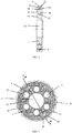
FIG. 2 is a front cross-sectional view of the transmission gear taken along the axially intermediate section thereof in accordance with a first embodiment of the present disclosure; -
FIG. 3 is a cross-sectional view of the transmission gear taken along a section A-A ofFIG. 2 ; -
FIG. 4 is a front cross-sectional view of the transmission gear taken along the axially intermediate section thereof in accordance with a second embodiment of the present disclosure; and -
FIG. 5 is a cross-sectional view of the transmission gear taken along a section B-B ofFIG. 4 . - The implementation and use of embodiments are discussed in detail hereinafter. However, it should be understood that the specific embodiments discussed herein are only illustrative of the specific embodiments of the present disclosure, and are not intended to limit the scope of the invention.
- It is to be noted that the drawings are not only intended to be illustrative of the present disclosure, but also to facilitate limiting of the present disclosure as necessary.
- As an example, the first and the second embodiments of the present disclosure are improvements based on the
plastic transmission gear 100 ofFIG. 1 . Therefore, the transmission gear according to the present disclosure may be a transmission gear provided in a gear box of a joint of the mechanical arm, for example. Of course, the disclosure is not limited to this. In fact, in the case that the strength condition is satisfied and the transmission load is sufficient, the transmission gear according to the present disclosure can be used as a transmission component in a deceleration mechanism of any type of industrial robot. - In the first embodiment shown in
FIGS. 2 and3 , the transmission gear according to the present disclosure comprises ametal ring 2 and aplastic gear member 1 integral on an outer and an inner portion with respect to the radial direction and two opposite end faces (i.e., thefirst end face 23 and the second end face 24) of themetal ring 2 by injection molding. More specifically, during the manufacturing process of such a transmission gear, themetal ring 2 which has been manufactured is first fixed at a specific position in the injection mold. In order to reduce the dimensional shrinkage of the plastic material, theouter ring surface 21 of themetal ring 2 is arranged adjacent to theouter circumference 11 of theplastic gear member 1 obtained, that is, the diameter of theouter ring surface 21 of themetal ring 2 is set to be slightly smaller than the diameter of theouter circumference 11 of theplastic gear member 1 and the diameter of theinner ring surface 22 of themetal ring 2, in the case of meeting the manufacturing conditions, is slightly smaller than the diameter of theouter ring surface 21. Injection molding is then performed to obtain aplastic gear member 1 coaxial with themetal ring 2 and cladding of themetal ring 2. Finally, the assembly formed from theplastic gear member 1 and themetal ring 2 is taken out of the injection mold to obtain such a transmission gear. - In the first embodiment, the shape of the
plastic gear member 1 is similar to that of theplastic transmission gear 100 ofFIG. 1 . Therefore, as shown, theouter region 15 of theplastic gear member 1 located outside themetal ring 2 in the radial direction has anouter circumference 11 that is tooth-shaped and theinner region 16 ofplastic gear member 1 located in themetal ring 2 in the radial direction is formed with aninput hole 12 through which the input shaft passes and a plurality ofoutput holes 13 through which the output member passes (the sixoutput holes 13 are illustrated) to transmit the torque from the input shaft to the plurality of output members. Theinput hole 12 is generally formed at a central location of the plastic gear member 1 (more specifically, theinner region 16 of the plastic gear member 1), and the plurality ofoutput holes 13 are formed around the circumference of theinput hole 12 at the same angular intervals, for example. The position and number of theoutput holes 13 are not limited herein and may be determined according to the actual needs. In addition, the torque may also be output by the transmission gear in other manners, so that theplastic gear member 1 may be formed with only theinput holes 12 and nooutput holes 13. - Since the
metal ring 2 needs to be accurately located relative to the injection mold before injection molding, a locating portion is required on themetal ring 2. In the first embodiment, as the radial dimension of themetal ring 2 is small, the locating portion includes twoprotrusions 25 that protrude from theinner ring surface 22 of themetal ring 2 and are symmetrical with respect to the center of themetal ring 2. Each of theprotrusions 25 is formed with a locatinghole 26, so that the locating member disposed on the injection mold passes through the locatingholes 26 to accurately locate themetal ring 2 on the injection mold and thus themetal ring 2 cannot rotate with respect to the injection mold. Moreover, the presence ofsuch protrusions 25 also prevents a relative displacement between themetal ring 2 and the plastic material after injection molding. The number and position of the projections 25 (and thus the locating holes 26) are not limited herein and may be determined according to the actual needs. Of course, the position of theprojections 25 may not interfere with the positions of the input holes 12 and the output holes 13. For example, the locating portion may include two ormore protrusions 25, which are preferably arranged at the same angular interval along the circumferential direction of themetal ring 2, and each of theprotrusions 25 is formed with a locatinghole 26. The term "interference" as used herein and hereinafter should be understood to refer to a positional coincidence in the radial direction. For example, theprotrusion 25 used herein cannot be spatially coincident with theinput hole 12 and theoutput hole 13 in the radial direction, that is, the presence of theprotrusion 25 may not influence the input shaft passing through theinput hole 12 and may not influence the output member passing through theoutput hole 13. - Further, during injection molding, the locating member disposed on the injection mold passes through the entire axial thickness of the transmission gear. In other words, as shown in
FIG. 3 , the locating member provided on the injection mold enables a pair of mountingholes 14 concentric with the locating holes 26 to be formed on theplastic gear member 1. Since the pair of mountingholes 14 is visible from the outer surface of the drive gear, when the transmission gear is mounted in the gearbox, the pair of mountingholes 14 can act as a reference to the initial mounting angle for ease of installation. - According to a preferred embodiment, not shown, the
outer ring surface 21 of themetal ring 2 is tooth-shaped similar to theouter circumference 11 of theplastic gear member 1. The term "similar" herein is to be understood to refer to designing the tooth shape of theouter ring surface 21 of themetal ring 2 to be a shape that is scaled down from the tooth shape of theouter circumference 11 of theplastic gear member 1 by a certain ratio. It is to be understood that subtle errors may be produced during the manufacturing process and they may be not exactly proportional. In this case, the annularouter region 15 has a substantially uniform radial dimension, which enables theouter ring surface 21 to better conform to the plastic material during injection molding, thus preventing relative displacement between the plastic material and the plasticmaterial metal ring 2 incurred by the uneven plastic material. However, such a tooth-shapedouter ring surface 21 increases the manufacturing cost of themetal ring 2. - As such, in the preferred embodiment shown, in order to reduce the manufacturing cost of the
metal ring 2, theouter ring surface 21 of themetal ring 2 has a simple circular shape. Especially in this case, in order to better fit theouter ring surface 21 with the plastic material during injection molding to prevent relative displacement between themetal ring 2 and the plastic material, theouter ring surface 21 can be bonded with the plastic materials more firmly in a specific manner. Preferably, a non-skid coating may be applied to theouter ring surface 21, or alternatively, theouter ring surface 21 may be processed by a particular corrosion treatment or a knurling treatment, for example, NMT (Nano Molding Technology) may be employed. - Also, in order to better fit the
inner ring surface 22 of themetal ring 2 and the two end faces with the plastic material during injection molding to prevent relative displacement between themetal ring 2 and the plastic material, theinner ring surface 22, thefirst end face 23 and thesecond end face 24 of themetal ring 2 can be bonded with the plastic materials more firmly in a particular manner. Preferably, theinner ring surface 22, thefirst end surface 23 and thesecond end surface 24 may be coated with a non-skid coating, or alternatively, theinner ring surface 22, thefirst end surface 23 and thesecond end surface 24 may be processed by a particular corrosion treatment or a knurling treatment to bond with the plastic materials more firmly. For example, NMT can be employed. - In order to facilitate mass production and reduce costs, the
metal ring 2 can be manufactured by a low-cost manufacturing method with a low-cost material. The material of themetal ring 2 is preferably selected from materials such as aluminum, aluminum alloy, steel, and the like. For example, a metal cylinder having a large axial length may be obtained from a particular profile of a selected material by extrusion or stamping, and the metal cylinder obtained may be sequentially divided into a plurality ofmetal rings 2 in an axial direction with intended axial length. - It is noted that the diameters of the
outer ring surface 21 and theinner ring surface 22 of themetal ring 2 need to be determined according to the actual needs. The diameter of the outer ring surface 21 (and therefore the distance between theouter ring surface 21 and theouter circumference 11 of the plastic gear member 1) generally depends on the plastic material parameters and the target machining accuracy of theplastic gear member 1. The diameter of theinner ring surface 22 generally depends on the particular property of theinner region 16 of theplastic gear member 1, such as the position of theinner ring surface 22 in the first embodiment that should not interfere with that of theoutput hole 13. Furthermore, the radial thickness of themetal ring 2 cannot be too small, since a radial thickness that is too small makes the manufacturing more difficult. - In the second embodiment shown in
FIGS. 4 and5 , theouter ring surface 21 of themetal ring 2 is likewise arranged adjacent to theouter circumference 11 of theplastic gear member 1 to be obtained, i.e. the diameter of theouter ring surface 21 of themetal ring 2 is set to be slightly smaller than that of theouter circumference 11 of theplastic gear member 1. This embodiment differs from the first embodiment in that theinner ring surface 22 of themetal ring 2 is expanded toward the center of the transmission gear up to the circumference of theinput hole 12. In other words, the diameter of theinner ring surface 22 of themetal ring 2 is equal to that of theinput hole 12. In fact, the diameter of theinner ring surface 22 of themetal ring 2 can be defined to be any value between the diameters of theouter ring surface 22 of themetal ring 2 and theinput hole 12 as long as that the manufacturing conditions are met. Of course, if theoutput hole 13 is provided, the positions of theouter ring surface 21 and theinner ring surface 22 of themetal ring 2 should not interfere with the position of theoutput hole 13. - In the second embodiment, if the
output hole 13 is provided, themetal ring 2 is formed with anopening 27 concentric with theoutput hole 13 for the output member to pass through. The diameter of theopening 27 generally depends on the plastic material parameters of the desiredplastic gear member 1, the target machining accuracy, and the size of theoutput hole 13. Further, the locating portion of themetal ring 2 includes two locatingholes 26 disposed adjacent to theouter ring surface 21 and symmetrical with respect to the center of themetal ring 2. The number and position of the locating holes 26 are not limited herein, and may be determined according to the actual needs. Of course, the position of the locating holes 26 may not interfere with the position of theopening 27, that is, the locating holes 26 may not coincide with the positions of theopenings 27. For example, the locating portion may include two or more locating holes 26, which are preferably arranged at the same angular interval along the circumferential direction of themetal ring 2. - The following exemplarily illustrates the effect of setting of the
metal ring 2 on the dimensional accuracy of the transmission gear. - For the
plastic transmission gear 100 ofFIG. 1 , assuming that theplastic transmission gear 100 has an average diameter of 50 mm and the plastic material of theplastic transmission gear 100 has a shrinkage ratio of 0.3% at the time of injection molding, the error of the radius of thetransmission gear 100 produced by an injection molding is 25∗0.3%=0.075 mm. - For the transmission gears according to the first and second embodiments of the invention, assuming that the
outer circumference 11 of theplastic gear member 1 has an average diameter of 50 mm, and the average distance between theouter circumference 11 and the circularouter ring surface 21 of themetal ring 2 is 3mm, and the error of the radius of the transmission gear after injection is 3∗0.3%=0.009mm. Therefore, compared to theplastic transmission gear 100 ofFig. 1 , the transmission gear according to the invention has a significantly reduced radial dimensional shrinkage at the time of injection molding, and it has good dimensional accuracy accordingly. Furthermore, the arrangement of themetal ring 2 also improves the strength and rigidity of the transmission gear, in particular, the bending of the transmission gear in the axial direction can be avoided. - The technical content and features of the invention have been disclosed above. However, it is to be understood that those skilled in the art can make various changes and improvements to the above disclosed concepts without departing from the inventive idea of the disclosure, but they are all within the scope of the disclosure.
- The description to the above embodiments is illustrative and not limiting, and the scope of the invention is defined by the following claims.
Claims (11)
- A transmission gear, comprising:a metal ring (2); anda plastic gear member (1) integral with the metal ring (2) by injection molding,wherein the metal ring (2) is coaxially wrapped in the plastic gear member (1) and provided with a locating portion for locating the metal ring (2) in an injection mold, wherein the plastic gear member (1) has an outer circumference (11) that is tooth-shaped, and an input hole (12) is formed on the plastic gear member (1) for an input shaft to pass through, and wherein an outer ring surface (21) of the metal ring (2) is arranged adjacent to the outer circumference (11), and an inner ring surface (22) of the metal ring (2) has a diameter greater than or equal to that of the input hole (12).
- The transmission gear of claim 1, wherein the locating portion comprises at least two locating holes (26) arranged in a circumferential direction of the metal ring (2) at the same angular interval, and a mounting hole (14) concentric with the locating hole (26) is formed on the plastic gear member (1).
- The transmission gear of any of the proceeding claims, wherein the outer ring surface (21) of the metal ring (2) is of a tooth shape similar to the outer circumference (11).
- The transmission gear of any of claims 1 and 2, wherein the outer ring surface (21) of the metal ring (2) is of a circular shape.
- The transmission gear of any of the proceeding claims, wherein a surface of the metal ring (2) is coated with a non-skid coating or processed by corrosion treatment or knurling treatment, to increase a degree of bonding with a plastic material.
- The transmission gear of any of the proceeding claims, wherein the material of the metal ring (2) is selected from aluminum, aluminum alloy and steel.
- The transmission gear of any of the proceeding claims, wherein the metal ring (2) is manufactured by extrusion or stamping.
- The transmission gear of any of the proceeding claims, wherein an output hole (13) is formed on the plastic gear member (1) for a plurality of output members to pass through, the position of the output hole (13) does not interfere with the positions of an outer ring surface (21), an inner ring surface (22) and a locating portion of the metal ring (2).
- The transmission gear of any of the proceeding claims, wherein the input hole (12) is formed at a center position of the plastic gear member (1), and the output hole (13) is formed around the circumference of the input hole (12) at the same angular interval.
- The transmission gear of any of claims 1-9, wherein the metal ring (2) is formed with an opening (27) concentric with the output hole (13) for the output member to pass through.
- A deceleration mechanism, comprising a transmission gear of any of claims 1 to 10.
Applications Claiming Priority (1)
| Application Number | Priority Date | Filing Date | Title |
|---|---|---|---|
| CN201822051009.1U CN209335964U (en) | 2018-12-07 | 2018-12-07 | Transmission gear and deceleration mechanism including it |
Publications (2)
| Publication Number | Publication Date |
|---|---|
| EP3663613A1 true EP3663613A1 (en) | 2020-06-10 |
| EP3663613B1 EP3663613B1 (en) | 2022-05-04 |
Family
ID=67749326
Family Applications (1)
| Application Number | Title | Priority Date | Filing Date |
|---|---|---|---|
| EP19211199.5A Active EP3663613B1 (en) | 2018-12-07 | 2019-11-25 | Transmission gear and deceleration mechanism comprising the same |
Country Status (3)
| Country | Link |
|---|---|
| US (1) | US11209078B2 (en) |
| EP (1) | EP3663613B1 (en) |
| CN (1) | CN209335964U (en) |
Families Citing this family (9)
| Publication number | Priority date | Publication date | Assignee | Title |
|---|---|---|---|---|
| US12194620B2 (en) | 2018-10-15 | 2025-01-14 | Oliver Crisipin Robotics Limited | Selectively flexible extension tool |
| US11702955B2 (en) | 2019-01-14 | 2023-07-18 | General Electric Company | Component repair system and method |
| US12405187B2 (en) | 2019-10-04 | 2025-09-02 | General Electric Company | Insertion apparatus for use with rotary machines |
| US12091981B2 (en) | 2020-06-11 | 2024-09-17 | General Electric Company | Insertion tool and method |
| US12416800B2 (en) | 2021-01-08 | 2025-09-16 | General Electric Company | Insertion tool |
| US12504616B2 (en) | 2021-01-08 | 2025-12-23 | General Electric Company | Insertion tool |
| US12276327B2 (en) * | 2021-01-15 | 2025-04-15 | Jtekt Corporation | Toothed pulley |
| US20230194234A1 (en) * | 2021-12-16 | 2023-06-22 | Oliver Crispin Robotics Limited | System and method of adjusting a tool |
| CN115072280B (en) * | 2022-07-26 | 2024-06-04 | 江苏胜牌科技有限公司 | Multi-wedge belt wheel for transmission roller |
Citations (4)
| Publication number | Priority date | Publication date | Assignee | Title |
|---|---|---|---|---|
| US4589860A (en) * | 1983-06-25 | 1986-05-20 | Skf Kugellagerfabriken Gmbh | Gear and method for making the same |
| US4600372A (en) * | 1985-08-20 | 1986-07-15 | Victor Barouh | Positioning system for molding plastic drive gear |
| US20090078066A1 (en) * | 2006-05-19 | 2009-03-26 | Keiper Gmbh & Co. Kg | Gear train for an actuator |
| CN201475284U (en) * | 2009-08-20 | 2010-05-19 | 无锡富佑工程塑料有限公司 | Plastic gear with embedded piece structure |
Family Cites Families (7)
| Publication number | Priority date | Publication date | Assignee | Title |
|---|---|---|---|---|
| US3199364A (en) * | 1963-09-10 | 1965-08-10 | Morse Chain Co | Composite plastic gear |
| US3696685A (en) * | 1970-04-21 | 1972-10-10 | Fiat Spa | Toothed pulleys |
| US5852951A (en) * | 1994-10-04 | 1998-12-29 | Briggs & Stratton Corporation | Composite gear and method of making same |
| JP3765232B2 (en) * | 2000-11-16 | 2006-04-12 | 株式会社ジェイテクト | Electric power steering apparatus and gear manufacturing method used therefor |
| US20070089555A1 (en) * | 2005-10-21 | 2007-04-26 | Koji Tomoda | Composite gear |
| JP5181483B2 (en) * | 2007-01-26 | 2013-04-10 | 株式会社ジェイテクト | Gear and electric power steering device |
| JP7339076B2 (en) * | 2019-08-30 | 2023-09-05 | ファナック株式会社 | Lightweight gear and its manufacturing method, gear train manufacturing method and robot |
-
2018
- 2018-12-07 CN CN201822051009.1U patent/CN209335964U/en active Active
-
2019
- 2019-11-25 US US16/693,921 patent/US11209078B2/en active Active
- 2019-11-25 EP EP19211199.5A patent/EP3663613B1/en active Active
Patent Citations (4)
| Publication number | Priority date | Publication date | Assignee | Title |
|---|---|---|---|---|
| US4589860A (en) * | 1983-06-25 | 1986-05-20 | Skf Kugellagerfabriken Gmbh | Gear and method for making the same |
| US4600372A (en) * | 1985-08-20 | 1986-07-15 | Victor Barouh | Positioning system for molding plastic drive gear |
| US20090078066A1 (en) * | 2006-05-19 | 2009-03-26 | Keiper Gmbh & Co. Kg | Gear train for an actuator |
| CN201475284U (en) * | 2009-08-20 | 2010-05-19 | 无锡富佑工程塑料有限公司 | Plastic gear with embedded piece structure |
Also Published As
| Publication number | Publication date |
|---|---|
| EP3663613B1 (en) | 2022-05-04 |
| US11209078B2 (en) | 2021-12-28 |
| US20200182345A1 (en) | 2020-06-11 |
| CN209335964U (en) | 2019-09-03 |
Similar Documents
| Publication | Publication Date | Title |
|---|---|---|
| US11209078B2 (en) | Transmission gear and deceleration mechanism comprising the same | |
| US9869330B2 (en) | Multipiece tolerance ring | |
| EP2754565B1 (en) | Lightweight hub unit with integrated bearing rings and processes for its manufacture | |
| EP3059472B1 (en) | Production method for fluid coupling and fluid coupling | |
| US20150354638A1 (en) | Synchronizer ring for a synchronization unit of a manual transmission and method for manufacturing such synchronizer ring | |
| US20190101190A1 (en) | Double helical gear and method of welding double helical gear | |
| US8075218B2 (en) | Prestressed shaft and hub connection having a perfect cone shape | |
| JP2025003466A (en) | Wave gear device and manufacturing system for wave gear device | |
| CN115815492B (en) | Machining method of flexible gear for harmonic speed reducer, flexible gear and harmonic speed reducer | |
| EP2634011A1 (en) | Spline forming method for hub unit, hub unit, spline forming method for joint, and joint | |
| US11187272B2 (en) | Method for mounting a sensor bearing unit, and sensor bearing unit adapted to such a method | |
| US20110255814A1 (en) | Bearing Assembly | |
| US12123458B2 (en) | Drive shafts | |
| US20230017225A1 (en) | Stamped hub for cast plastic | |
| US10948021B2 (en) | Flanged wheel hub unit and assembly method | |
| US10859124B2 (en) | Synchronizer ring for a synchronization unit of a manual transmission and method for the production thereof | |
| US20250226733A1 (en) | Friction welded stator carrier | |
| US11008904B2 (en) | Camshaft phaser cover element and camshaft phaser | |
| EP4571138A1 (en) | Pivotable element | |
| WO2020170782A1 (en) | Stator core, rotor core, and motor | |
| US11480217B2 (en) | Bearing unit with optimized radially inner ring | |
| IT202000007048A1 (en) | BEARING UNIT WITH CONCENTRIC CLAMPING COLLAR | |
| CN104242570B (en) | Segmented device for rotor butt joint assembly and method for conducting rotor butt joint assembly with device | |
| CN210111769U (en) | Group of motors | |
| CN103415400A (en) | Shaft member for rolling bearing device of wheel |
Legal Events
| Date | Code | Title | Description |
|---|---|---|---|
| PUAI | Public reference made under article 153(3) epc to a published international application that has entered the european phase |
Free format text: ORIGINAL CODE: 0009012 |
|
| STAA | Information on the status of an ep patent application or granted ep patent |
Free format text: STATUS: REQUEST FOR EXAMINATION WAS MADE |
|
| 17P | Request for examination filed |
Effective date: 20191125 |
|
| AK | Designated contracting states |
Kind code of ref document: A1 Designated state(s): AL AT BE BG CH CY CZ DE DK EE ES FI FR GB GR HR HU IE IS IT LI LT LU LV MC MK MT NL NO PL PT RO RS SE SI SK SM TR |
|
| AX | Request for extension of the european patent |
Extension state: BA ME |
|
| RBV | Designated contracting states (corrected) |
Designated state(s): AL AT BE BG CH CY CZ DE DK EE ES FI FR GB GR HR HU IE IS IT LI LT LU LV MC MK MT NL NO PL PT RO RS SE SI SK SM TR |
|
| STAA | Information on the status of an ep patent application or granted ep patent |
Free format text: STATUS: EXAMINATION IS IN PROGRESS |
|
| 17Q | First examination report despatched |
Effective date: 20210726 |
|
| GRAP | Despatch of communication of intention to grant a patent |
Free format text: ORIGINAL CODE: EPIDOSNIGR1 |
|
| STAA | Information on the status of an ep patent application or granted ep patent |
Free format text: STATUS: GRANT OF PATENT IS INTENDED |
|
| INTG | Intention to grant announced |
Effective date: 20211210 |
|
| GRAS | Grant fee paid |
Free format text: ORIGINAL CODE: EPIDOSNIGR3 |
|
| GRAA | (expected) grant |
Free format text: ORIGINAL CODE: 0009210 |
|
| STAA | Information on the status of an ep patent application or granted ep patent |
Free format text: STATUS: THE PATENT HAS BEEN GRANTED |
|
| RAP3 | Party data changed (applicant data changed or rights of an application transferred) |
Owner name: ABB SCHWEIZ AG |
|
| AK | Designated contracting states |
Kind code of ref document: B1 Designated state(s): AL AT BE BG CH CY CZ DE DK EE ES FI FR GB GR HR HU IE IS IT LI LT LU LV MC MK MT NL NO PL PT RO RS SE SI SK SM TR |
|
| REG | Reference to a national code |
Ref country code: GB Ref legal event code: FG4D |
|
| REG | Reference to a national code |
Ref country code: CH Ref legal event code: EP |
|
| REG | Reference to a national code |
Ref country code: AT Ref legal event code: REF Ref document number: 1489362 Country of ref document: AT Kind code of ref document: T Effective date: 20220515 |
|
| REG | Reference to a national code |
Ref country code: IE Ref legal event code: FG4D Ref country code: DE Ref legal event code: R096 Ref document number: 602019014425 Country of ref document: DE |
|
| REG | Reference to a national code |
Ref country code: LT Ref legal event code: MG9D |
|
| REG | Reference to a national code |
Ref country code: NL Ref legal event code: MP Effective date: 20220504 |
|
| REG | Reference to a national code |
Ref country code: AT Ref legal event code: MK05 Ref document number: 1489362 Country of ref document: AT Kind code of ref document: T Effective date: 20220504 |
|
| PG25 | Lapsed in a contracting state [announced via postgrant information from national office to epo] |
Ref country code: SE Free format text: LAPSE BECAUSE OF FAILURE TO SUBMIT A TRANSLATION OF THE DESCRIPTION OR TO PAY THE FEE WITHIN THE PRESCRIBED TIME-LIMIT Effective date: 20220504 Ref country code: PT Free format text: LAPSE BECAUSE OF FAILURE TO SUBMIT A TRANSLATION OF THE DESCRIPTION OR TO PAY THE FEE WITHIN THE PRESCRIBED TIME-LIMIT Effective date: 20220905 Ref country code: NO Free format text: LAPSE BECAUSE OF FAILURE TO SUBMIT A TRANSLATION OF THE DESCRIPTION OR TO PAY THE FEE WITHIN THE PRESCRIBED TIME-LIMIT Effective date: 20220804 Ref country code: NL Free format text: LAPSE BECAUSE OF FAILURE TO SUBMIT A TRANSLATION OF THE DESCRIPTION OR TO PAY THE FEE WITHIN THE PRESCRIBED TIME-LIMIT Effective date: 20220504 Ref country code: LT Free format text: LAPSE BECAUSE OF FAILURE TO SUBMIT A TRANSLATION OF THE DESCRIPTION OR TO PAY THE FEE WITHIN THE PRESCRIBED TIME-LIMIT Effective date: 20220504 Ref country code: HR Free format text: LAPSE BECAUSE OF FAILURE TO SUBMIT A TRANSLATION OF THE DESCRIPTION OR TO PAY THE FEE WITHIN THE PRESCRIBED TIME-LIMIT Effective date: 20220504 Ref country code: GR Free format text: LAPSE BECAUSE OF FAILURE TO SUBMIT A TRANSLATION OF THE DESCRIPTION OR TO PAY THE FEE WITHIN THE PRESCRIBED TIME-LIMIT Effective date: 20220805 Ref country code: FI Free format text: LAPSE BECAUSE OF FAILURE TO SUBMIT A TRANSLATION OF THE DESCRIPTION OR TO PAY THE FEE WITHIN THE PRESCRIBED TIME-LIMIT Effective date: 20220504 Ref country code: ES Free format text: LAPSE BECAUSE OF FAILURE TO SUBMIT A TRANSLATION OF THE DESCRIPTION OR TO PAY THE FEE WITHIN THE PRESCRIBED TIME-LIMIT Effective date: 20220504 Ref country code: BG Free format text: LAPSE BECAUSE OF FAILURE TO SUBMIT A TRANSLATION OF THE DESCRIPTION OR TO PAY THE FEE WITHIN THE PRESCRIBED TIME-LIMIT Effective date: 20220804 Ref country code: AT Free format text: LAPSE BECAUSE OF FAILURE TO SUBMIT A TRANSLATION OF THE DESCRIPTION OR TO PAY THE FEE WITHIN THE PRESCRIBED TIME-LIMIT Effective date: 20220504 |
|
| PG25 | Lapsed in a contracting state [announced via postgrant information from national office to epo] |
Ref country code: RS Free format text: LAPSE BECAUSE OF FAILURE TO SUBMIT A TRANSLATION OF THE DESCRIPTION OR TO PAY THE FEE WITHIN THE PRESCRIBED TIME-LIMIT Effective date: 20220504 Ref country code: PL Free format text: LAPSE BECAUSE OF FAILURE TO SUBMIT A TRANSLATION OF THE DESCRIPTION OR TO PAY THE FEE WITHIN THE PRESCRIBED TIME-LIMIT Effective date: 20220504 Ref country code: LV Free format text: LAPSE BECAUSE OF FAILURE TO SUBMIT A TRANSLATION OF THE DESCRIPTION OR TO PAY THE FEE WITHIN THE PRESCRIBED TIME-LIMIT Effective date: 20220504 Ref country code: IS Free format text: LAPSE BECAUSE OF FAILURE TO SUBMIT A TRANSLATION OF THE DESCRIPTION OR TO PAY THE FEE WITHIN THE PRESCRIBED TIME-LIMIT Effective date: 20220904 |
|
| PG25 | Lapsed in a contracting state [announced via postgrant information from national office to epo] |
Ref country code: SM Free format text: LAPSE BECAUSE OF FAILURE TO SUBMIT A TRANSLATION OF THE DESCRIPTION OR TO PAY THE FEE WITHIN THE PRESCRIBED TIME-LIMIT Effective date: 20220504 Ref country code: SK Free format text: LAPSE BECAUSE OF FAILURE TO SUBMIT A TRANSLATION OF THE DESCRIPTION OR TO PAY THE FEE WITHIN THE PRESCRIBED TIME-LIMIT Effective date: 20220504 Ref country code: RO Free format text: LAPSE BECAUSE OF FAILURE TO SUBMIT A TRANSLATION OF THE DESCRIPTION OR TO PAY THE FEE WITHIN THE PRESCRIBED TIME-LIMIT Effective date: 20220504 Ref country code: EE Free format text: LAPSE BECAUSE OF FAILURE TO SUBMIT A TRANSLATION OF THE DESCRIPTION OR TO PAY THE FEE WITHIN THE PRESCRIBED TIME-LIMIT Effective date: 20220504 Ref country code: DK Free format text: LAPSE BECAUSE OF FAILURE TO SUBMIT A TRANSLATION OF THE DESCRIPTION OR TO PAY THE FEE WITHIN THE PRESCRIBED TIME-LIMIT Effective date: 20220504 Ref country code: CZ Free format text: LAPSE BECAUSE OF FAILURE TO SUBMIT A TRANSLATION OF THE DESCRIPTION OR TO PAY THE FEE WITHIN THE PRESCRIBED TIME-LIMIT Effective date: 20220504 |
|
| REG | Reference to a national code |
Ref country code: DE Ref legal event code: R097 Ref document number: 602019014425 Country of ref document: DE |
|
| PLBE | No opposition filed within time limit |
Free format text: ORIGINAL CODE: 0009261 |
|
| STAA | Information on the status of an ep patent application or granted ep patent |
Free format text: STATUS: NO OPPOSITION FILED WITHIN TIME LIMIT |
|
| PG25 | Lapsed in a contracting state [announced via postgrant information from national office to epo] |
Ref country code: AL Free format text: LAPSE BECAUSE OF FAILURE TO SUBMIT A TRANSLATION OF THE DESCRIPTION OR TO PAY THE FEE WITHIN THE PRESCRIBED TIME-LIMIT Effective date: 20220504 |
|
| 26N | No opposition filed |
Effective date: 20230207 |
|
| PG25 | Lapsed in a contracting state [announced via postgrant information from national office to epo] |
Ref country code: SI Free format text: LAPSE BECAUSE OF FAILURE TO SUBMIT A TRANSLATION OF THE DESCRIPTION OR TO PAY THE FEE WITHIN THE PRESCRIBED TIME-LIMIT Effective date: 20220504 |
|
| PG25 | Lapsed in a contracting state [announced via postgrant information from national office to epo] |
Ref country code: MC Free format text: LAPSE BECAUSE OF FAILURE TO SUBMIT A TRANSLATION OF THE DESCRIPTION OR TO PAY THE FEE WITHIN THE PRESCRIBED TIME-LIMIT Effective date: 20220504 |
|
| REG | Reference to a national code |
Ref country code: CH Ref legal event code: PL |
|
| REG | Reference to a national code |
Ref country code: BE Ref legal event code: MM Effective date: 20221130 |
|
| PG25 | Lapsed in a contracting state [announced via postgrant information from national office to epo] |
Ref country code: LI Free format text: LAPSE BECAUSE OF NON-PAYMENT OF DUE FEES Effective date: 20221130 Ref country code: CH Free format text: LAPSE BECAUSE OF NON-PAYMENT OF DUE FEES Effective date: 20221130 |
|
| PG25 | Lapsed in a contracting state [announced via postgrant information from national office to epo] |
Ref country code: LU Free format text: LAPSE BECAUSE OF NON-PAYMENT OF DUE FEES Effective date: 20221125 |
|
| PG25 | Lapsed in a contracting state [announced via postgrant information from national office to epo] |
Ref country code: IE Free format text: LAPSE BECAUSE OF NON-PAYMENT OF DUE FEES Effective date: 20221125 |
|
| PG25 | Lapsed in a contracting state [announced via postgrant information from national office to epo] |
Ref country code: FR Free format text: LAPSE BECAUSE OF NON-PAYMENT OF DUE FEES Effective date: 20221130 Ref country code: BE Free format text: LAPSE BECAUSE OF NON-PAYMENT OF DUE FEES Effective date: 20221130 |
|
| PG25 | Lapsed in a contracting state [announced via postgrant information from national office to epo] |
Ref country code: IT Free format text: LAPSE BECAUSE OF FAILURE TO SUBMIT A TRANSLATION OF THE DESCRIPTION OR TO PAY THE FEE WITHIN THE PRESCRIBED TIME-LIMIT Effective date: 20220504 |
|
| PG25 | Lapsed in a contracting state [announced via postgrant information from national office to epo] |
Ref country code: HU Free format text: LAPSE BECAUSE OF FAILURE TO SUBMIT A TRANSLATION OF THE DESCRIPTION OR TO PAY THE FEE WITHIN THE PRESCRIBED TIME-LIMIT; INVALID AB INITIO Effective date: 20191125 |
|
| PG25 | Lapsed in a contracting state [announced via postgrant information from national office to epo] |
Ref country code: CY Free format text: LAPSE BECAUSE OF FAILURE TO SUBMIT A TRANSLATION OF THE DESCRIPTION OR TO PAY THE FEE WITHIN THE PRESCRIBED TIME-LIMIT Effective date: 20220504 |
|
| PG25 | Lapsed in a contracting state [announced via postgrant information from national office to epo] |
Ref country code: MK Free format text: LAPSE BECAUSE OF FAILURE TO SUBMIT A TRANSLATION OF THE DESCRIPTION OR TO PAY THE FEE WITHIN THE PRESCRIBED TIME-LIMIT Effective date: 20220504 |
|
| PG25 | Lapsed in a contracting state [announced via postgrant information from national office to epo] |
Ref country code: TR Free format text: LAPSE BECAUSE OF FAILURE TO SUBMIT A TRANSLATION OF THE DESCRIPTION OR TO PAY THE FEE WITHIN THE PRESCRIBED TIME-LIMIT Effective date: 20220504 |
|
| GBPC | Gb: european patent ceased through non-payment of renewal fee |
Effective date: 20231125 |
|
| PG25 | Lapsed in a contracting state [announced via postgrant information from national office to epo] |
Ref country code: MT Free format text: LAPSE BECAUSE OF FAILURE TO SUBMIT A TRANSLATION OF THE DESCRIPTION OR TO PAY THE FEE WITHIN THE PRESCRIBED TIME-LIMIT Effective date: 20220504 |
|
| PG25 | Lapsed in a contracting state [announced via postgrant information from national office to epo] |
Ref country code: GB Free format text: LAPSE BECAUSE OF NON-PAYMENT OF DUE FEES Effective date: 20231125 |
|
| PG25 | Lapsed in a contracting state [announced via postgrant information from national office to epo] |
Ref country code: GB Free format text: LAPSE BECAUSE OF NON-PAYMENT OF DUE FEES Effective date: 20231125 |
|
| PG25 | Lapsed in a contracting state [announced via postgrant information from national office to epo] |
Ref country code: BG Free format text: LAPSE BECAUSE OF FAILURE TO SUBMIT A TRANSLATION OF THE DESCRIPTION OR TO PAY THE FEE WITHIN THE PRESCRIBED TIME-LIMIT Effective date: 20220504 |
|
| PG25 | Lapsed in a contracting state [announced via postgrant information from national office to epo] |
Ref country code: BG Free format text: LAPSE BECAUSE OF FAILURE TO SUBMIT A TRANSLATION OF THE DESCRIPTION OR TO PAY THE FEE WITHIN THE PRESCRIBED TIME-LIMIT Effective date: 20220504 |
|
| PGFP | Annual fee paid to national office [announced via postgrant information from national office to epo] |
Ref country code: DE Payment date: 20251119 Year of fee payment: 7 |