EP3663570B1 - Engine and mixed-gas intake device thereof - Google Patents
Engine and mixed-gas intake device thereof Download PDFInfo
- Publication number
- EP3663570B1 EP3663570B1 EP17936441.9A EP17936441A EP3663570B1 EP 3663570 B1 EP3663570 B1 EP 3663570B1 EP 17936441 A EP17936441 A EP 17936441A EP 3663570 B1 EP3663570 B1 EP 3663570B1
- Authority
- EP
- European Patent Office
- Prior art keywords
- gas intake
- blades
- gas
- hybrid
- section
- Prior art date
- Legal status (The legal status is an assumption and is not a legal conclusion. Google has not performed a legal analysis and makes no representation as to the accuracy of the status listed.)
- Active
Links
Images




Classifications
-
- F—MECHANICAL ENGINEERING; LIGHTING; HEATING; WEAPONS; BLASTING
- F02—COMBUSTION ENGINES; HOT-GAS OR COMBUSTION-PRODUCT ENGINE PLANTS
- F02M—SUPPLYING COMBUSTION ENGINES IN GENERAL WITH COMBUSTIBLE MIXTURES OR CONSTITUENTS THEREOF
- F02M26/00—Engine-pertinent apparatus for adding exhaust gases to combustion-air, main fuel or fuel-air mixture, e.g. by exhaust gas recirculation [EGR] systems
- F02M26/13—Arrangement or layout of EGR passages, e.g. in relation to specific engine parts or for incorporation of accessories
- F02M26/17—Arrangement or layout of EGR passages, e.g. in relation to specific engine parts or for incorporation of accessories in relation to the intake system
- F02M26/21—Arrangement or layout of EGR passages, e.g. in relation to specific engine parts or for incorporation of accessories in relation to the intake system with EGR valves located at or near the connection to the intake system
-
- F—MECHANICAL ENGINEERING; LIGHTING; HEATING; WEAPONS; BLASTING
- F02—COMBUSTION ENGINES; HOT-GAS OR COMBUSTION-PRODUCT ENGINE PLANTS
- F02M—SUPPLYING COMBUSTION ENGINES IN GENERAL WITH COMBUSTIBLE MIXTURES OR CONSTITUENTS THEREOF
- F02M26/00—Engine-pertinent apparatus for adding exhaust gases to combustion-air, main fuel or fuel-air mixture, e.g. by exhaust gas recirculation [EGR] systems
- F02M26/65—Constructional details of EGR valves
- F02M26/70—Flap valves; Rotary valves; Sliding valves; Resilient valves
-
- F—MECHANICAL ENGINEERING; LIGHTING; HEATING; WEAPONS; BLASTING
- F02—COMBUSTION ENGINES; HOT-GAS OR COMBUSTION-PRODUCT ENGINE PLANTS
- F02M—SUPPLYING COMBUSTION ENGINES IN GENERAL WITH COMBUSTIBLE MIXTURES OR CONSTITUENTS THEREOF
- F02M26/00—Engine-pertinent apparatus for adding exhaust gases to combustion-air, main fuel or fuel-air mixture, e.g. by exhaust gas recirculation [EGR] systems
- F02M26/13—Arrangement or layout of EGR passages, e.g. in relation to specific engine parts or for incorporation of accessories
- F02M26/17—Arrangement or layout of EGR passages, e.g. in relation to specific engine parts or for incorporation of accessories in relation to the intake system
- F02M26/19—Means for improving the mixing of air and recirculated exhaust gases, e.g. venturis or multiple openings to the intake system
-
- F—MECHANICAL ENGINEERING; LIGHTING; HEATING; WEAPONS; BLASTING
- F02—COMBUSTION ENGINES; HOT-GAS OR COMBUSTION-PRODUCT ENGINE PLANTS
- F02M—SUPPLYING COMBUSTION ENGINES IN GENERAL WITH COMBUSTIBLE MIXTURES OR CONSTITUENTS THEREOF
- F02M26/00—Engine-pertinent apparatus for adding exhaust gases to combustion-air, main fuel or fuel-air mixture, e.g. by exhaust gas recirculation [EGR] systems
- F02M26/52—Systems for actuating EGR valves
- F02M26/64—Systems for actuating EGR valves the EGR valve being operated together with an intake air throttle
Definitions
- the present disclosure relates to the technical field of exhaust gas circulating utilization, and in particular to a hybrid gas intake device of an engine, and an engine including the hybrid gas intake device.
- a gas inlet of a conventional engine is provided with a hybrid gas intake device.
- a conventional hybrid gas intake device includes a gas intake pipe and an exhaust gas intake pipe connected to a side wall of the gas intake pipe.
- the exhaust gas intake pipe is provided with an EGR valve that is a butterfly valve or a poppet valve. That is, the EGR valve that is the butterfly valve or the poppet valve is mounted independently in an EGR loop, to control an EGR flow.
- the gas intake pipe is provided with a mixer for mixing air and the exhaust gas.
- the exhaust gas intake pipe is required to be provided with a valve body to control intake flow of the exhaust gas, and is also required to be provided with a mixer to mix the air and the exhaust gas, which results in a large overall volume of the hybrid gas intake device.
- the exhaust gas turbocharger includes a turbine arranged in the exhaust gas discharge system and a compressor arranged in the intake system.
- the exhaust gas recirculation includes a recirculation line system which branches off from the exhaust gas discharge system downstream of the turbine and is in communication with the intake system.
- the intake system is provided with an adjustable guide device, including four rotatable guide blades, shafts, and blade roots. Each of the blades and a corresponding blade root form a rotatable L-shaped profile.
- the shafts rotates to drive the blade roots to move, so that the blade roots block the inlet opening in a first position and release this inlet opening in a second position.
- An object of the present disclosure is to provide a hybrid gas intake device of an engine, which has a small overall volume. Another object of the present disclosure is to provide an engine including the hybrid gas intake device.
- a hybrid gas intake device of an engine is defined in claim 1.
- the hybrid gas intake device includes a gas intake pipe. A side wall of the gas intake pipe is provided with an exhaust gas inlet.
- the hybrid gas intake device further includes multiple blades arranged in the gas intake pipe and a flow control device configured to adjust an interval between each two adjacent blades. The multiple blades are arranged at an end of the exhaust gas inlet and distributed along a ring, and an exhaust gas intake space is formed between the multiple blades and the side wall of the gas intake pipe.
- the flow control device includes a connection element, a fixed plate, a rotatable plate, and a driving device configured to drive the rotatable plate to rotate.
- the fixed plate is fixed relative to the gas intake pipe, each of the multiple blades is connected to the fixed plate by a first hinge pin, and the first hinge pin is in clearance fit with the fixed plate;
- the rotatable plate is fixedly connected to a second hinge pin that is in one-to-one correspondence with the first hinge pin, and the second hinge pin is rotatably connected to the connection element;
- the connection element is fixedly connected to the first hinge pin, and the first hinge pin is in one-to-one correspondence with the blade.
- the multiple blades are arranged along a circle, a centerline of the circle coincides with an axis of the gas intake pipe, and an interval between each two adjacent blades of the multiple blades is the same.
- the number of the fixed plate is two, and the number of the rotatable plate is two.
- the rotatable plates are in one-to-one correspondence with the fixed plates.
- the two fixed plates are arranged at two opposite ends of the multiple blades respectively.
- the gas intake pipe includes an air intake section, a blade mounting section, and a gas outlet section that are sequentially arranged along a gas moving direction.
- the multiple blades and the flow control device are located in the blade mounting section.
- An inner diameter of the fixed plate is equal to an inner diameter of the air intake section.
- the inner diameter of the air intake section is equal to an inner diameter of the gas outlet section.
- the rotatable plate is sleeved outside the fixed plate.
- An outer wall of the rotatable plate is in clearance fit with a side wall of the blade mounting section.
- the blade mounting section is integrally formed with the gas outlet section, and the blade mounting section is detachably connected to the air intake section.
- the blade has a fusiform cross section in a direction perpendicular to an axis of the gas intake pipe.
- the blade is integrally formed.
- an anticorrosive layer is provided on a surface of the blade.
- An engine which includes an engine body and a hybrid gas intake device connected to a gas inlet of the engine body, where the hybrid gas intake device of the engine is the above described hybrid gas intake device.
- the hybrid gas intake device includes a gas intake pipe, a blade arranged in the gas intake pipe and a flow control device configured to adjust an interval between two adjacent blades.
- a side wall of the gas intake pipe is provided with an exhaust gas inlet.
- the blade is arranged at an end of the exhaust gas inlet, a number of the blade is more than one, the more than one blade is distributed along a ring, and exhaust gas intake space is formed between the blade and the side wall of the gas intake pipe.
- the interval between two adjacent blades is adjusted by the flow control device, to control the intake flow of the exhaust gas.
- the exhaust gas flows into the gas intake pipe through the interval between two adj acent blades and is mixed with the air. Finally, the mixed gas flows into the engine body through the gas intake pipe.
- the interval between two adjacent blades is adjusted by the flow control device so as to adjust the intake flow of the exhaust air, eliminating the need to install a dedicated valve. Since the multiple blades are distributed along a ring, the exhaust gas and the air can be well-mixed after the exhaust gas flows into the gas intake pipe, eliminating the need to install a dedicated mixer. Therefore, the overall volume of the hybrid gas intake device can be effectively reduced.
- a core of the present disclosure is to provide a hybrid gas intake device of an engine, which has a small volumn. Another object of the present disclosure is to provide an engine including the hybrid gas intake device.
- a hybrid gas intake device of an engine includes a gas intake pipe, a blade 3 arranged in the gas intake pipe, and a flow control device configured to adjust an interval between two adjacent blades 3.
- a side wall of the gas intake pipe is provided with an exhaust gas inlet.
- the blade 3 is arranged at an end of the exhaust gas inlet, a number of the blade 3 is more than one, and the more than one blade 3 is distributed along a ring.
- Exhaust gas intake space is formed between the blade 3 and the side wall of the gas intake pipe.
- the blade 3 is preferably a metal blade to prolong a service life of the hybrid gas intake device.
- the blade 3 may be made of steel.
- the interval between two adjacent blades 3 is adjusted by the flow control device, to control the intake flow of the exhaust gas.
- the exhaust gas flows into the gas intake pipe through the interval between two adjacent blades 3 and is mixed with the air. Finally, the mixed gas flows into the engine body through the gas intake pipe.
- a gas flow direction during operation is described as follows.
- the exhaust gas flows into a gas passage of the gas intake pipe sequentially through an inlet al of a mixing pipe, a region b between an outer contour of the blades 3 and the gas intake pipe, and a region c between adjacent blades 3.
- fresh air flows into the gas passage of the gas intake pipe through an inlet a2 of the gas intake pip.
- the exhaust gas is mixed with the fresh air during flowing, and then the mixed gas is discharged through a gas outlet d of the gas intake pipe.
- the interval between two adjacent blades 3 is adjusted by the flow control device so as to adjust the intake flow of the exhaust air, thereby eliminating the need to install a dedicated valve. Since the multiple blades 3 are distributed along a ring, the exhaust gas and the air can be well-mixed after the exhaust gas flows into the gas intake pipe, thereby eliminating the need to install a dedicated mixer. That is, an area of a cross section through which the exhaust gas flows into the gas passage is changed, so as to control an EGR flow. The exhaust gas flows into the gas passage through the interval between adjacent blades 3, to form annular air inflow, so that the EGR exhaust gas and the fresh air can be well-mixed. In this way, a function of controlling the EGR flow and a function of controlling the air and the exhaust gas to be well-mixed can be achieved by one module, thereby effectively reducing the overall volume of the hybrid gas intake device.
- the more than one blade 3 is arranged along a circle, a centerline of the circle coincides with an axis of the gas intake pipe, and an interval between each two adjacent blades 3 is the same.
- the flow control device includes a connection element 6, a fixed plate 2, a rotatable plate 5, and a driving device configured to drive the rotatable plate 5 to rotate.
- the driving device may be a rotary cylinder, a motor or the like.
- the motor may drive the rotatable plate 5 to rotate through a gear assembly.
- the motor is a stepping motor.
- the fixed plate 2 is fixed relative to the gas intake pipe.
- the blade 3 is connected to the fixed plate 2 by a first hinge pin.
- the first hinge pin is in clearance fit with the fixed plate 2.
- the rotatable plate 5 is fixedly connected to a second hinge pin 4 in one-to-one correspondence with the first hinge pin.
- the second hinge pin 4 is rotatably connected to the connection element 6.
- the connection element 6 is fixedly connected to the first hinge pin.
- the first hinge pin is in one-to-one correspondence with the blade 3..
- the flow control device includes two fixed plates 2 and two rotatable plates 5.
- the rotatable plates 5 are in one-to-one correspondence with the fixed plates 2.
- the two fixed plates 2 are arranged at two opposite ends of the blade 3 respectively.
- each rotatable plate 5 corresponds to a respective connection element 6.
- the flow control device includes a fixed plate 2, a rotatable plate 5, and a driving device configured to drive the rotatable plate 5 to rotate.
- the driving device may be a rotary cylinder a motor or the like.
- the blade 3 is provided with a first rotatable shaft rotatably connected to the fixed plate 2 and a second rotatable shaft connected to the rotatable plate 5.
- the rotatable plate 5 is provided with a groove for the second rotatable shaft to slide along.
- the exhaust gas flows into the gas passage through the region c between the blades 3 and is mixed with the fresh gas.
- a cross section formed by the blades for gas intake is changed, so as to control the EGR flow.
- the blades 3 are fully opened, and an area of the region C between the blades 3 is large, thus the EGR flow has a large value.
- the area of the region C between the blades 3 is small, thus the EGR flow has a small value.
- the EGR flow may has a minimum value of zero.
- the gas intake pipe includes an air intake section 7, a blade mounting section 9, and a gas outlet section 1 that are sequentially arranged along a gas moving direction.
- the blade 3 and the flow control device are located in the blade mounting section 9.
- the air intake section 7, the blade 3 mounting section, and the gas outlet section 1 are detachably connected sequentially.
- an inner diameter of the fixed plate 2 is equal to an inner diameter of the air intake section 7, and the inner diameter of the air intake section 7 is equal to an inner diameter of the gas outlet section 1.
- the rotatable plate 5 is sleeved outside the fixed plate 2.
- An outer wall of the rotatable plate 5 is in clearance fit with a side wall of the blade mounting section 9. That is, the gas intake pipe has a smooth inner wall.
- the blade mounting section 9 is integrally formed with the gas outlet section 1, and the blade mounting section 9 is detachably connected to the air intake section 7.
- the blade mounting section 9 is provided with a first flange end
- the air intake section 7 is provided with a second flange end.
- the first flange end is connected to the second flange end by a threaded fastener 8.
- multiple threaded fasteners 8 are uniformly distributed along a circumferential direction of the blade mounting section 9. Since the blade mounting section 9 is detachably connected to the air intake section 7, it is convenient to clean the blade 3 subsequently.
- the blade 3 has a fusiform cross section in a direction perpendicular to an axis of the gas intake pipe. That is, the blade 3 is thick in the middle and thin at two ends.
- the blade 3 is integrally formed.
- an anticorrosive layer is provided on a surface of the blade 3.
- the engine includes an engine body and a hybrid gas intake device connected to a gas inlet of the engine body, where the hybrid gas intake device of the engine is the hybrid gas intake device according to any of the above embodiments.
- Embodiments in this specification are described in a progressive way, each of which emphasizes the differences from others, and reference can be made to each other of the embodiments for the same or similar parts among the embodiments.
Landscapes
- Engineering & Computer Science (AREA)
- Chemical & Material Sciences (AREA)
- Combustion & Propulsion (AREA)
- Mechanical Engineering (AREA)
- General Engineering & Computer Science (AREA)
- Exhaust-Gas Circulating Devices (AREA)
Description
- The present disclosure relates to the technical field of exhaust gas circulating utilization, and in particular to a hybrid gas intake device of an engine, and an engine including the hybrid gas intake device.
- In recent years, destruction of the global ecological environment and greenhouse effect caused by automobile exhaust pollution and CO2 emission become increasingly serious. A car with low exhaust pollution and low fuel consumption can mitigate global warming and the destruction of ecological balance caused by the global greenhouse effect. In order to reduce environmental pollution, with EGR (Exhaust Gas Recirculation) technology, exhaust gas discharged by the engine is reintroduced into a gas intake pipe and is mixed with fresh gas, and then the mixed gas flows into a combustion chamber for combustion. In this way, NOx emission of the engine can be effectively reduced.
- In order to utilize the exhaust gas, a gas inlet of a conventional engine is provided with a hybrid gas intake device. Specifically, a conventional hybrid gas intake device includes a gas intake pipe and an exhaust gas intake pipe connected to a side wall of the gas intake pipe. The exhaust gas intake pipe is provided with an EGR valve that is a butterfly valve or a poppet valve. That is, the EGR valve that is the butterfly valve or the poppet valve is mounted independently in an EGR loop, to control an EGR flow. The gas intake pipe is provided with a mixer for mixing air and the exhaust gas.
- However, the exhaust gas intake pipe is required to be provided with a valve body to control intake flow of the exhaust gas, and is also required to be provided with a mixer to mix the air and the exhaust gas, which results in a large overall volume of the hybrid gas intake device.
- Therefore, how to reduce the overall volume of the hybrid gas intake device is a technical problem desired to be solved by those skilled in the art.
-
DE 20 2016 103188 U discloses an internal combustion engine, including an intake system, exhaust gas turbocharger, and an exhaust gas recirculation. The exhaust gas turbocharger includes a turbine arranged in the exhaust gas discharge system and a compressor arranged in the intake system. The exhaust gas recirculation includes a recirculation line system which branches off from the exhaust gas discharge system downstream of the turbine and is in communication with the intake system. The intake system is provided with an adjustable guide device, including four rotatable guide blades, shafts, and blade roots. Each of the blades and a corresponding blade root form a rotatable L-shaped profile. The shafts rotates to drive the blade roots to move, so that the blade roots block the inlet opening in a first position and release this inlet opening in a second position. - An object of the present disclosure is to provide a hybrid gas intake device of an engine, which has a small overall volume. Another object of the present disclosure is to provide an engine including the hybrid gas intake device.
- In order to achieve the above objects, a hybrid gas intake device of an engine is defined in
claim 1. The hybrid gas intake device includes a gas intake pipe. A side wall of the gas intake pipe is provided with an exhaust gas inlet. The hybrid gas intake device further includes multiple blades arranged in the gas intake pipe and a flow control device configured to adjust an interval between each two adjacent blades. The multiple blades are arranged at an end of the exhaust gas inlet and distributed along a ring, and an exhaust gas intake space is formed between the multiple blades and the side wall of the gas intake pipe. The flow control device includes a connection element, a fixed plate, a rotatable plate, and a driving device configured to drive the rotatable plate to rotate. The fixed plate is fixed relative to the gas intake pipe, each of the multiple blades is connected to the fixed plate by a first hinge pin, and the first hinge pin is in clearance fit with the fixed plate; the rotatable plate is fixedly connected to a second hinge pin that is in one-to-one correspondence with the first hinge pin, and the second hinge pin is rotatably connected to the connection element; the connection element is fixedly connected to the first hinge pin, and the first hinge pin is in one-to-one correspondence with the blade. - Preferably, the multiple blades are arranged along a circle, a centerline of the circle coincides with an axis of the gas intake pipe, and an interval between each two adjacent blades of the multiple blades is the same.
- Preferably, the number of the fixed plate is two, and the number of the rotatable plate is two. The rotatable plates are in one-to-one correspondence with the fixed plates. The two fixed plates are arranged at two opposite ends of the multiple blades respectively.
- Preferably, the gas intake pipe includes an air intake section, a blade mounting section, and a gas outlet section that are sequentially arranged along a gas moving direction. The multiple blades and the flow control device are located in the blade mounting section. An inner diameter of the fixed plate is equal to an inner diameter of the air intake section. The inner diameter of the air intake section is equal to an inner diameter of the gas outlet section. The rotatable plate is sleeved outside the fixed plate. An outer wall of the rotatable plate is in clearance fit with a side wall of the blade mounting section.
- Preferably, the blade mounting section is integrally formed with the gas outlet section, and the blade mounting section is detachably connected to the air intake section.
- Preferably, the blade has a fusiform cross section in a direction perpendicular to an axis of the gas intake pipe.
- Preferably, the blade is integrally formed.
- Preferably, an anticorrosive layer is provided on a surface of the blade.
- An engine is provided, which includes an engine body and a hybrid gas intake device connected to a gas inlet of the engine body, where the hybrid gas intake device of the engine is the above described hybrid gas intake device.
- In the above technical solutions, the hybrid gas intake device according to the present disclosure includes a gas intake pipe, a blade arranged in the gas intake pipe and a flow control device configured to adjust an interval between two adjacent blades. A side wall of the gas intake pipe is provided with an exhaust gas inlet. The blade is arranged at an end of the exhaust gas inlet, a number of the blade is more than one, the more than one blade is distributed along a ring, and exhaust gas intake space is formed between the blade and the side wall of the gas intake pipe. In practical operation of the engine, the interval between two adjacent blades is adjusted by the flow control device, to control the intake flow of the exhaust gas. The exhaust gas flows into the gas intake pipe through the interval between two adj acent blades and is mixed with the air. Finally, the mixed gas flows into the engine body through the gas intake pipe.
- It can be seen from the above description that in the hybrid gas intake device according to the present disclosure, the interval between two adjacent blades is adjusted by the flow control device so as to adjust the intake flow of the exhaust air, eliminating the need to install a dedicated valve. Since the multiple blades are distributed along a ring, the exhaust gas and the air can be well-mixed after the exhaust gas flows into the gas intake pipe, eliminating the need to install a dedicated mixer. Therefore, the overall volume of the hybrid gas intake device can be effectively reduced.
-
-
Figure 1 is a three-dimensional structural diagram of a hybrid gas intake device in a case that blades are opened according to an embodiment of the present disclosure; -
Figure 2 is a three-dimensional structural diagram of the hybrid gas intake device from another perspective in the case that blades are opened according to an embodiment of the present disclosure; -
Figure 3 is a schematic structural diagram of the hybrid gas intake device in the case that blades are opened according to an embodiment of the present disclosure; -
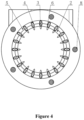
Figure 4 is a structural schematic diagram of the hybrid gas intake device shown inFigure 3 along an A-A direction; -
Figure 5 is a structural schematic diagram of the hybrid gas intake device shown inFigure 3 along a B-B direction; -
Figure 6 is a top view of the hybrid gas intake device in a case that blades are closed according to an embodiment of the present disclosure; -
Figure 7 is a three-dimensional structural diagram of the hybrid gas intake device in the case that blades are closed according to an embodiment of the present disclosure; -
Figure 8 is a three-dimensional structural diagram of the hybrid gas intake device from another perspective in the case that blades are closed according to an embodiment of the present disclosure; -
Figure 9 is a schematic structural diagram of the hybrid gas intake device in the case that blades are closed according to an embodiment of the present disclosure; -
Figure 10 is a schematic structural diagram of the hybrid gas intake device shown inFigure 9 along a C-C direction; -
Figure 11 is a schematic structural diagram of the hybrid gas intake device shown inFigure 9 along a D-D direction; and -
Figure 12 is a top view of the hybrid gas intake device in the case that blades are closed according to an embodiment of the present disclosure. - A core of the present disclosure is to provide a hybrid gas intake device of an engine, which has a small volumn. Another object of the present disclosure is to provide an engine including the hybrid gas intake device.
- In order to enable those skilled in the art to better understand technical solutions of the present disclosure, the technical solutions of the present disclosure are further described in detail below with reference to the drawings and embodiments.
- Reference is made to
Figures 1 to 12 . In an embodiment, a hybrid gas intake device of an engine according to an embodiment of the present disclosure includes a gas intake pipe, ablade 3 arranged in the gas intake pipe, and a flow control device configured to adjust an interval between twoadjacent blades 3. A side wall of the gas intake pipe is provided with an exhaust gas inlet. Theblade 3 is arranged at an end of the exhaust gas inlet, a number of theblade 3 is more than one, and the more than oneblade 3 is distributed along a ring. Exhaust gas intake space is formed between theblade 3 and the side wall of the gas intake pipe. As temperature of the exhaust gas is usually high, theblade 3 is preferably a metal blade to prolong a service life of the hybrid gas intake device. In an embodiment, theblade 3 may be made of steel. - In practical operation of the engine, the interval between two
adjacent blades 3 is adjusted by the flow control device, to control the intake flow of the exhaust gas. The exhaust gas flows into the gas intake pipe through the interval between twoadjacent blades 3 and is mixed with the air. Finally, the mixed gas flows into the engine body through the gas intake pipe. - In an embodiment, a gas flow direction during operation is described as follows. The exhaust gas flows into a gas passage of the gas intake pipe sequentially through an inlet al of a mixing pipe, a region b between an outer contour of the
blades 3 and the gas intake pipe, and a region c betweenadjacent blades 3. In this case, fresh air flows into the gas passage of the gas intake pipe through an inlet a2 of the gas intake pip. The exhaust gas is mixed with the fresh air during flowing, and then the mixed gas is discharged through a gas outlet d of the gas intake pipe. - It can be seen from the above description that in the hybrid gas intake device according to the embodiment of the present disclosure, the interval between two
adjacent blades 3 is adjusted by the flow control device so as to adjust the intake flow of the exhaust air, thereby eliminating the need to install a dedicated valve. Since themultiple blades 3 are distributed along a ring, the exhaust gas and the air can be well-mixed after the exhaust gas flows into the gas intake pipe, thereby eliminating the need to install a dedicated mixer. That is, an area of a cross section through which the exhaust gas flows into the gas passage is changed, so as to control an EGR flow. The exhaust gas flows into the gas passage through the interval betweenadjacent blades 3, to form annular air inflow, so that the EGR exhaust gas and the fresh air can be well-mixed. In this way, a function of controlling the EGR flow and a function of controlling the air and the exhaust gas to be well-mixed can be achieved by one module, thereby effectively reducing the overall volume of the hybrid gas intake device. - Preferably, the more than one
blade 3 is arranged along a circle, a centerline of the circle coincides with an axis of the gas intake pipe, and an interval between each twoadjacent blades 3 is the same. - Preferably, the flow control device includes a
connection element 6, afixed plate 2, arotatable plate 5, and a driving device configured to drive therotatable plate 5 to rotate. In an embodiment, the driving device may be a rotary cylinder, a motor or the like. In an embodiment, the motor may drive therotatable plate 5 to rotate through a gear assembly. Preferably, the motor is a stepping motor. The fixedplate 2 is fixed relative to the gas intake pipe. Theblade 3 is connected to the fixedplate 2 by a first hinge pin. The first hinge pin is in clearance fit with the fixedplate 2. Therotatable plate 5 is fixedly connected to asecond hinge pin 4 in one-to-one correspondence with the first hinge pin. Thesecond hinge pin 4 is rotatably connected to theconnection element 6. Theconnection element 6 is fixedly connected to the first hinge pin. The first hinge pin is in one-to-one correspondence with theblade 3.. - In order to improve stability, preferably, the flow control device includes two fixed
plates 2 and tworotatable plates 5. Therotatable plates 5 are in one-to-one correspondence with the fixedplates 2. The two fixedplates 2 are arranged at two opposite ends of theblade 3 respectively. In an embodiment, eachrotatable plate 5 corresponds to arespective connection element 6. - In another embodiment, the flow control device includes a fixed
plate 2, arotatable plate 5, and a driving device configured to drive therotatable plate 5 to rotate. In an embodiment, the driving device may be a rotary cylinder a motor or the like. Theblade 3 is provided with a first rotatable shaft rotatably connected to the fixedplate 2 and a second rotatable shaft connected to therotatable plate 5. Therotatable plate 5 is provided with a groove for the second rotatable shaft to slide along. - The exhaust gas flows into the gas passage through the region c between the
blades 3 and is mixed with the fresh gas. After angles of theblades 3 are changed, a cross section formed by the blades for gas intake is changed, so as to control the EGR flow. As shown inFigure 1 , theblades 3 are fully opened, and an area of the region C between theblades 3 is large, thus the EGR flow has a large value. As shown inFigure 7 , the area of the region C between theblades 3 is small, thus the EGR flow has a small value. The EGR flow may has a minimum value of zero. - In an embodiment, the gas intake pipe includes an
air intake section 7, ablade mounting section 9, and agas outlet section 1 that are sequentially arranged along a gas moving direction. Theblade 3 and the flow control device are located in theblade mounting section 9. In an embodiment, theair intake section 7, theblade 3 mounting section, and thegas outlet section 1 are detachably connected sequentially. - In order to reduce obstruction to gas flow, preferably, an inner diameter of the fixed
plate 2 is equal to an inner diameter of theair intake section 7, and the inner diameter of theair intake section 7 is equal to an inner diameter of thegas outlet section 1. Therotatable plate 5 is sleeved outside the fixedplate 2. An outer wall of therotatable plate 5 is in clearance fit with a side wall of theblade mounting section 9. That is, the gas intake pipe has a smooth inner wall. - In order to facilitate assembly and disassembly of the hybrid gas intake device, preferably, the
blade mounting section 9 is integrally formed with thegas outlet section 1, and theblade mounting section 9 is detachably connected to theair intake section 7. In an embodiment, theblade mounting section 9 is provided with a first flange end, and theair intake section 7 is provided with a second flange end. The first flange end is connected to the second flange end by a threadedfastener 8. Preferably, multiple threadedfasteners 8 are uniformly distributed along a circumferential direction of theblade mounting section 9. Since theblade mounting section 9 is detachably connected to theair intake section 7, it is convenient to clean theblade 3 subsequently. - In order to prolong a service life of the
blade 3, preferably, theblade 3 has a fusiform cross section in a direction perpendicular to an axis of the gas intake pipe. That is, theblade 3 is thick in the middle and thin at two ends. - In order to facilitate manufacture of the
blade 3 and improve manufacturing efficiency, preferably, theblade 3 is integrally formed. - Based on the above technical solutions, in order to prolong the service life of the hybrid gas intake device, preferably, an anticorrosive layer is provided on a surface of the
blade 3. - An engine is provided according to the present disclosure. The engine includes an engine body and a hybrid gas intake device connected to a gas inlet of the engine body, where the hybrid gas intake device of the engine is the hybrid gas intake device according to any of the above embodiments.
- Embodiments in this specification are described in a progressive way, each of which emphasizes the differences from others, and reference can be made to each other of the embodiments for the same or similar parts among the embodiments.
Claims (9)
- A hybrid gas intake device of an engine, comprising:a gas intake pipe, wherein a side wall of the gas intake pipe is provided with an exhaust gas inlet;a plurality of blades (3) arranged in the gas intake pipe; anda flow control device configured to adjust an interval between each two adjacent blades (3) of the plurality of blades (3),wherein the plurality of blades (3) are arranged at an end of the exhaust gas inlet and distributed along a ring, and an exhaust gas intake space is formed between the plurality of blades (3) and the side wall of the gas intake pipe;whereinthe flow control device comprises a connection element (6), a fixed plate (2), a rotatable plate (5), and a driving device configured to drive the rotatable plate (5) to rotate; whereinthe fixed plate (2) is fixed relative to the gas intake pipe;each of the plurality of blades (3) is connected to the fixed plate (2) by a first hinge pin, and the first hinge pin is in clearance fit with the fixed plate (2);characterized in thatthe rotatable plate (5) is fixedly connected to a second hinge pin (4) that is in one-to-one correspondence with the first hinge pin, and the second hinge pin (4) is rotatably connected to the connection element (6); and in thatthe connection element (6) is fixedly connected to the first hinge pin, and the first hinge pin is in one-to-one correspondence with the blade (3).
- The hybrid gas intake device according to claim 1, wherein the plurality of blades (3) is distributed along a circle, a centerline of the circle coincides with an axis of the gas intake pipe, and an interval between each two adjacent blades (3) of the plurality of blades (3) is the same.
- The hybrid gas intake device according to claim 1, wherein the number of the fixed plate (2) is two, and the number of the rotatable plate (5) is two; the two rotatable plates (5) are in one-to-one correspondence with the two fixed plates (2), and the two fixed plates (2) are arranged at two opposite ends of the plurality of blades (3) respectively.
- The hybrid gas intake device according to claim 3, wherein the gas intake pipe comprises an air intake section (7), a blade mounting section (9), and a gas outlet section (1) that are sequentially arranged along a gas moving direction, and
wherein the plurality of blades (3) and the flow control device are located in the blade mounting section (9), an inner diameter of each of the fixed plates (2) is equal to an inner diameter of the air intake section (7), the inner diameter of the air intake section (7) is equal to an inner diameter of the gas outlet section (1), each of the rotatable plates (5) is sleeved outside the corresponding fixed plate (2), and an outer wall of each of the rotatable plates (5) is in clearance fit with a side wall of the blade mounting section (9). - The hybrid gas intake device according to claim 4, wherein the blade mounting section (9) is integrally formed with the gas outlet section (1), and the blade mounting section (9) is detachably connected to the air intake section (7).
- The hybrid gas intake device according to claim 1, wherein each of the plurality of blades (3) has a fusiform cross section in a direction perpendicular to an axis of the gas intake pipe.
- The hybrid gas intake device according to claim 6, wherein each of the plurality of blades (3) is integrally formed.
- The hybrid gas intake device according to any one of claims 1 to 7, wherein an anticorrosive layer is provided on a surface of each of the plurality of blades (3).
- An engine, comprising:an engine body; anda hybrid gas intake device connected to a gas inlet of the engine body, wherein the hybrid gas intake device of the engine is the hybrid gas intake device according to any one of claims 1 to 8.
Applications Claiming Priority (1)
| Application Number | Priority Date | Filing Date | Title |
|---|---|---|---|
| PCT/CN2017/118996 WO2019127098A1 (en) | 2017-12-27 | 2017-12-27 | Engine and mixed-gas intake device thereof |
Publications (4)
| Publication Number | Publication Date |
|---|---|
| EP3663570A1 EP3663570A1 (en) | 2020-06-10 |
| EP3663570A4 EP3663570A4 (en) | 2020-12-16 |
| EP3663570C0 EP3663570C0 (en) | 2024-10-09 |
| EP3663570B1 true EP3663570B1 (en) | 2024-10-09 |
Family
ID=67064237
Family Applications (1)
| Application Number | Title | Priority Date | Filing Date |
|---|---|---|---|
| EP17936441.9A Active EP3663570B1 (en) | 2017-12-27 | 2017-12-27 | Engine and mixed-gas intake device thereof |
Country Status (3)
| Country | Link |
|---|---|
| US (1) | US11002227B2 (en) |
| EP (1) | EP3663570B1 (en) |
| WO (1) | WO2019127098A1 (en) |
Families Citing this family (4)
| Publication number | Priority date | Publication date | Assignee | Title |
|---|---|---|---|---|
| CN108180091A (en) * | 2017-12-26 | 2018-06-19 | 潍柴动力股份有限公司 | EGR mixes regulating device and internal combustion engine |
| US11499489B2 (en) * | 2021-03-25 | 2022-11-15 | Ford Global Technologies, Llc | Annular ring mixer with vanes |
| CN115219202B (en) * | 2021-04-14 | 2023-09-15 | 广州汽车集团股份有限公司 | An internal intubation tube selection test device, an internal intubation tube selection method and device |
| CN116291984B (en) * | 2023-04-14 | 2025-07-22 | 浙江大学嘉兴研究院 | Exhaust gas treatment device based on EGR |
Family Cites Families (12)
| Publication number | Priority date | Publication date | Assignee | Title |
|---|---|---|---|---|
| EP1152141B1 (en) | 2000-05-05 | 2005-02-09 | Siemens Aktiengesellschaft | Method and apparatus for recirculating exhaust gas into an inlet air stream |
| EP2653708A1 (en) * | 2010-12-13 | 2013-10-23 | Mitsubishi Electric Corporation | Exhaust gas circulation valve |
| CN102230429A (en) | 2011-04-29 | 2011-11-02 | 奇瑞汽车股份有限公司 | EGR (Exhaust Gas Recirculation) gas mixer |
| JP2013087720A (en) * | 2011-10-20 | 2013-05-13 | Isuzu Motors Ltd | Venturi for egr |
| DE102012101851B4 (en) * | 2012-03-06 | 2014-06-05 | Pierburg Gmbh | Abgaseinleitvorrichtung for an internal combustion engine |
| US20160097351A1 (en) * | 2014-10-07 | 2016-04-07 | Borgwarner Inc. | Swirl type lp - egr throttle mechanism |
| JP6464860B2 (en) * | 2015-03-23 | 2019-02-06 | 株式会社デンソー | Exhaust gas recirculation device |
| WO2017034548A1 (en) | 2015-08-25 | 2017-03-02 | Borgwarner Inc. | Mixing device and method of making and using the same |
| DE202016103188U1 (en) * | 2016-06-07 | 2016-06-29 | Ford Global Technologies, Llc | Charged internal combustion engine with exhaust gas recirculation |
| CN106884746B (en) * | 2017-02-23 | 2019-04-23 | 浙江吉利控股集团有限公司 | A gas mixing device for engine exhaust gas circulation system |
| CN108104986B (en) | 2017-12-27 | 2023-12-15 | 潍柴动力股份有限公司 | Engine and its mixed air intake device |
| CN207761833U (en) | 2017-12-27 | 2018-08-24 | 潍柴动力股份有限公司 | Engine and its mixed admission device |
-
2017
- 2017-12-27 US US16/650,955 patent/US11002227B2/en not_active Expired - Fee Related
- 2017-12-27 EP EP17936441.9A patent/EP3663570B1/en active Active
- 2017-12-27 WO PCT/CN2017/118996 patent/WO2019127098A1/en not_active Ceased
Also Published As
| Publication number | Publication date |
|---|---|
| EP3663570C0 (en) | 2024-10-09 |
| EP3663570A1 (en) | 2020-06-10 |
| US11002227B2 (en) | 2021-05-11 |
| WO2019127098A1 (en) | 2019-07-04 |
| US20200408173A1 (en) | 2020-12-31 |
| EP3663570A4 (en) | 2020-12-16 |
Similar Documents
| Publication | Publication Date | Title |
|---|---|---|
| US9845770B2 (en) | Asymmetric double-entry turbine | |
| CN106014492B (en) | Variable geometry nozzle for partitioned volutes | |
| US10662870B2 (en) | Variable geometry wastegate turbine | |
| US20120285427A1 (en) | Exhaust manifold assembly with integrated exhaust gas recirculation bypass | |
| KR101866853B1 (en) | Rotatable switching valve | |
| US9157396B2 (en) | Nozzled turbine | |
| US11002227B2 (en) | Engine and mixed-gas intake device thereof | |
| EP1957784B1 (en) | Three-pass heat exchanger for an egr system | |
| JP5556295B2 (en) | EGR device for turbocharged engine | |
| KR20140001912A (en) | Simplified variable geometry turbocharger with increased flow range | |
| CN108104986B (en) | Engine and its mixed air intake device | |
| WO2017087062A1 (en) | System and method fo exhaust gas recirculation | |
| SE1050440A1 (en) | Turbine housing for superchargers | |
| CN106884746A (en) | A kind of gas mixer for the engine exhaust circulatory system | |
| EP2861834B1 (en) | A device for controlling a gas flow, an exhaust aftertreatment system and a system for propelling a vehicle | |
| WO2012016366A1 (en) | Pulse flow-channel-variable turbine device | |
| CN207761833U (en) | Engine and its mixed admission device | |
| CN203906120U (en) | Combined engine for unmanned combat aircraft | |
| KR20160066067A (en) | EGR mixing apparatus of engine | |
| CN102536435B (en) | Hybrid flow variable spiral case | |
| US20130104539A1 (en) | Turbine for and exhaust gas turbocharger | |
| CN104879199B (en) | A kind of self-con-tained unit for realizing motor-vehicle tail-gas Multi-class propagation | |
| CN205422987U (en) | Circulation air intake system | |
| WO2008054567A1 (en) | Turbocharger having inclined turbine housing volutes | |
| CN109653905A (en) | Ship machine egr system and application method equipped with variable throat diameter Venturi tube |
Legal Events
| Date | Code | Title | Description |
|---|---|---|---|
| STAA | Information on the status of an ep patent application or granted ep patent |
Free format text: STATUS: THE INTERNATIONAL PUBLICATION HAS BEEN MADE |
|
| PUAI | Public reference made under article 153(3) epc to a published international application that has entered the european phase |
Free format text: ORIGINAL CODE: 0009012 |
|
| STAA | Information on the status of an ep patent application or granted ep patent |
Free format text: STATUS: REQUEST FOR EXAMINATION WAS MADE |
|
| 17P | Request for examination filed |
Effective date: 20200305 |
|
| AK | Designated contracting states |
Kind code of ref document: A1 Designated state(s): AL AT BE BG CH CY CZ DE DK EE ES FI FR GB GR HR HU IE IS IT LI LT LU LV MC MK MT NL NO PL PT RO RS SE SI SK SM TR |
|
| AX | Request for extension of the european patent |
Extension state: BA ME |
|
| A4 | Supplementary search report drawn up and despatched |
Effective date: 20201113 |
|
| RIC1 | Information provided on ipc code assigned before grant |
Ipc: F02M 26/21 20160101AFI20201109BHEP Ipc: F02M 26/70 20160101ALI20201109BHEP Ipc: F02M 26/19 20160101ALI20201109BHEP |
|
| DAV | Request for validation of the european patent (deleted) | ||
| DAX | Request for extension of the european patent (deleted) | ||
| STAA | Information on the status of an ep patent application or granted ep patent |
Free format text: STATUS: EXAMINATION IS IN PROGRESS |
|
| 17Q | First examination report despatched |
Effective date: 20220203 |
|
| GRAP | Despatch of communication of intention to grant a patent |
Free format text: ORIGINAL CODE: EPIDOSNIGR1 |
|
| STAA | Information on the status of an ep patent application or granted ep patent |
Free format text: STATUS: GRANT OF PATENT IS INTENDED |
|
| INTG | Intention to grant announced |
Effective date: 20240506 |
|
| GRAS | Grant fee paid |
Free format text: ORIGINAL CODE: EPIDOSNIGR3 |
|
| GRAA | (expected) grant |
Free format text: ORIGINAL CODE: 0009210 |
|
| STAA | Information on the status of an ep patent application or granted ep patent |
Free format text: STATUS: THE PATENT HAS BEEN GRANTED |
|
| AK | Designated contracting states |
Kind code of ref document: B1 Designated state(s): AL AT BE BG CH CY CZ DE DK EE ES FI FR GB GR HR HU IE IS IT LI LT LU LV MC MK MT NL NO PL PT RO RS SE SI SK SM TR |
|
| REG | Reference to a national code |
Ref country code: CH Ref legal event code: EP |
|
| REG | Reference to a national code |
Ref country code: DE Ref legal event code: R096 Ref document number: 602017085465 Country of ref document: DE |
|
| REG | Reference to a national code |
Ref country code: IE Ref legal event code: FG4D |
|
| U01 | Request for unitary effect filed |
Effective date: 20241022 |
|
| U07 | Unitary effect registered |
Designated state(s): AT BE BG DE DK EE FI FR IT LT LU LV MT NL PT RO SE SI Effective date: 20241105 |
|
| U20 | Renewal fee for the european patent with unitary effect paid |
Year of fee payment: 8 Effective date: 20241220 |
|
| PG25 | Lapsed in a contracting state [announced via postgrant information from national office to epo] |
Ref country code: IS Free format text: LAPSE BECAUSE OF FAILURE TO SUBMIT A TRANSLATION OF THE DESCRIPTION OR TO PAY THE FEE WITHIN THE PRESCRIBED TIME-LIMIT Effective date: 20250209 Ref country code: HR Free format text: LAPSE BECAUSE OF FAILURE TO SUBMIT A TRANSLATION OF THE DESCRIPTION OR TO PAY THE FEE WITHIN THE PRESCRIBED TIME-LIMIT Effective date: 20241009 |
|
| PG25 | Lapsed in a contracting state [announced via postgrant information from national office to epo] |
Ref country code: ES Free format text: LAPSE BECAUSE OF FAILURE TO SUBMIT A TRANSLATION OF THE DESCRIPTION OR TO PAY THE FEE WITHIN THE PRESCRIBED TIME-LIMIT Effective date: 20241009 |
|
| PG25 | Lapsed in a contracting state [announced via postgrant information from national office to epo] |
Ref country code: NO Free format text: LAPSE BECAUSE OF FAILURE TO SUBMIT A TRANSLATION OF THE DESCRIPTION OR TO PAY THE FEE WITHIN THE PRESCRIBED TIME-LIMIT Effective date: 20250109 |
|
| PG25 | Lapsed in a contracting state [announced via postgrant information from national office to epo] |
Ref country code: GR Free format text: LAPSE BECAUSE OF FAILURE TO SUBMIT A TRANSLATION OF THE DESCRIPTION OR TO PAY THE FEE WITHIN THE PRESCRIBED TIME-LIMIT Effective date: 20250110 |
|
| PG25 | Lapsed in a contracting state [announced via postgrant information from national office to epo] |
Ref country code: PL Free format text: LAPSE BECAUSE OF FAILURE TO SUBMIT A TRANSLATION OF THE DESCRIPTION OR TO PAY THE FEE WITHIN THE PRESCRIBED TIME-LIMIT Effective date: 20241009 |
|
| PG25 | Lapsed in a contracting state [announced via postgrant information from national office to epo] |
Ref country code: RS Free format text: LAPSE BECAUSE OF FAILURE TO SUBMIT A TRANSLATION OF THE DESCRIPTION OR TO PAY THE FEE WITHIN THE PRESCRIBED TIME-LIMIT Effective date: 20250109 |
|
| PG25 | Lapsed in a contracting state [announced via postgrant information from national office to epo] |
Ref country code: SM Free format text: LAPSE BECAUSE OF FAILURE TO SUBMIT A TRANSLATION OF THE DESCRIPTION OR TO PAY THE FEE WITHIN THE PRESCRIBED TIME-LIMIT Effective date: 20241009 |
|
| PG25 | Lapsed in a contracting state [announced via postgrant information from national office to epo] |
Ref country code: MC Free format text: LAPSE BECAUSE OF FAILURE TO SUBMIT A TRANSLATION OF THE DESCRIPTION OR TO PAY THE FEE WITHIN THE PRESCRIBED TIME-LIMIT Effective date: 20241009 |
|
| PG25 | Lapsed in a contracting state [announced via postgrant information from national office to epo] |
Ref country code: SK Free format text: LAPSE BECAUSE OF FAILURE TO SUBMIT A TRANSLATION OF THE DESCRIPTION OR TO PAY THE FEE WITHIN THE PRESCRIBED TIME-LIMIT Effective date: 20241009 |
|
| PG25 | Lapsed in a contracting state [announced via postgrant information from national office to epo] |
Ref country code: CZ Free format text: LAPSE BECAUSE OF FAILURE TO SUBMIT A TRANSLATION OF THE DESCRIPTION OR TO PAY THE FEE WITHIN THE PRESCRIBED TIME-LIMIT Effective date: 20241009 |
|
| REG | Reference to a national code |
Ref country code: CH Ref legal event code: PL |
|
| PLBE | No opposition filed within time limit |
Free format text: ORIGINAL CODE: 0009261 |
|
| STAA | Information on the status of an ep patent application or granted ep patent |
Free format text: STATUS: NO OPPOSITION FILED WITHIN TIME LIMIT |
|
| 26N | No opposition filed |
Effective date: 20250710 |
|
| GBPC | Gb: european patent ceased through non-payment of renewal fee |
Effective date: 20250109 |
|
| PG25 | Lapsed in a contracting state [announced via postgrant information from national office to epo] |
Ref country code: GB Free format text: LAPSE BECAUSE OF NON-PAYMENT OF DUE FEES Effective date: 20250109 |
|
| PG25 | Lapsed in a contracting state [announced via postgrant information from national office to epo] |
Ref country code: CH Free format text: LAPSE BECAUSE OF NON-PAYMENT OF DUE FEES Effective date: 20241231 |
|
| PG25 | Lapsed in a contracting state [announced via postgrant information from national office to epo] |
Ref country code: IE Free format text: LAPSE BECAUSE OF NON-PAYMENT OF DUE FEES Effective date: 20241227 |
|
| U20 | Renewal fee for the european patent with unitary effect paid |
Year of fee payment: 9 Effective date: 20251128 |
|
| PG25 | Lapsed in a contracting state [announced via postgrant information from national office to epo] |
Ref country code: CY Free format text: LAPSE BECAUSE OF FAILURE TO SUBMIT A TRANSLATION OF THE DESCRIPTION OR TO PAY THE FEE WITHIN THE PRESCRIBED TIME-LIMIT Effective date: 20241009 |
|
| PG25 | Lapsed in a contracting state [announced via postgrant information from national office to epo] |
Ref country code: TR Free format text: LAPSE BECAUSE OF FAILURE TO SUBMIT A TRANSLATION OF THE DESCRIPTION OR TO PAY THE FEE WITHIN THE PRESCRIBED TIME-LIMIT Effective date: 20241009 |
|
| PG25 | Lapsed in a contracting state [announced via postgrant information from national office to epo] |
Ref country code: HU Free format text: LAPSE BECAUSE OF FAILURE TO SUBMIT A TRANSLATION OF THE DESCRIPTION OR TO PAY THE FEE WITHIN THE PRESCRIBED TIME-LIMIT; INVALID AB INITIO Effective date: 20171227 |