EP3663553A1 - System for thermal management of an after treatment system (ats) - Google Patents
System for thermal management of an after treatment system (ats) Download PDFInfo
- Publication number
- EP3663553A1 EP3663553A1 EP19213964.0A EP19213964A EP3663553A1 EP 3663553 A1 EP3663553 A1 EP 3663553A1 EP 19213964 A EP19213964 A EP 19213964A EP 3663553 A1 EP3663553 A1 EP 3663553A1
- Authority
- EP
- European Patent Office
- Prior art keywords
- jacket
- liquid
- ats
- thermal
- insulated tank
- Prior art date
- Legal status (The legal status is an assumption and is not a legal conclusion. Google has not performed a legal analysis and makes no representation as to the accuracy of the status listed.)
- Granted
Links
Images

Classifications
-
- F—MECHANICAL ENGINEERING; LIGHTING; HEATING; WEAPONS; BLASTING
- F01—MACHINES OR ENGINES IN GENERAL; ENGINE PLANTS IN GENERAL; STEAM ENGINES
- F01N—GAS-FLOW SILENCERS OR EXHAUST APPARATUS FOR MACHINES OR ENGINES IN GENERAL; GAS-FLOW SILENCERS OR EXHAUST APPARATUS FOR INTERNAL-COMBUSTION ENGINES
- F01N3/00—Exhaust or silencing apparatus having means for purifying, rendering innocuous, or otherwise treating exhaust
- F01N3/08—Exhaust or silencing apparatus having means for purifying, rendering innocuous, or otherwise treating exhaust for rendering innocuous
- F01N3/10—Exhaust or silencing apparatus having means for purifying, rendering innocuous, or otherwise treating exhaust for rendering innocuous by thermal or catalytic conversion of noxious components of exhaust
- F01N3/18—Exhaust or silencing apparatus having means for purifying, rendering innocuous, or otherwise treating exhaust for rendering innocuous by thermal or catalytic conversion of noxious components of exhaust characterised by methods of operation; Control
- F01N3/20—Exhaust or silencing apparatus having means for purifying, rendering innocuous, or otherwise treating exhaust for rendering innocuous by thermal or catalytic conversion of noxious components of exhaust characterised by methods of operation; Control specially adapted for catalytic conversion
- F01N3/2006—Periodically heating or cooling catalytic reactors, e.g. at cold starting or overheating
-
- F—MECHANICAL ENGINEERING; LIGHTING; HEATING; WEAPONS; BLASTING
- F01—MACHINES OR ENGINES IN GENERAL; ENGINE PLANTS IN GENERAL; STEAM ENGINES
- F01N—GAS-FLOW SILENCERS OR EXHAUST APPARATUS FOR MACHINES OR ENGINES IN GENERAL; GAS-FLOW SILENCERS OR EXHAUST APPARATUS FOR INTERNAL-COMBUSTION ENGINES
- F01N11/00—Monitoring or diagnostic devices for exhaust-gas treatment apparatus
-
- F—MECHANICAL ENGINEERING; LIGHTING; HEATING; WEAPONS; BLASTING
- F01—MACHINES OR ENGINES IN GENERAL; ENGINE PLANTS IN GENERAL; STEAM ENGINES
- F01N—GAS-FLOW SILENCERS OR EXHAUST APPARATUS FOR MACHINES OR ENGINES IN GENERAL; GAS-FLOW SILENCERS OR EXHAUST APPARATUS FOR INTERNAL-COMBUSTION ENGINES
- F01N11/00—Monitoring or diagnostic devices for exhaust-gas treatment apparatus
- F01N11/002—Monitoring or diagnostic devices for exhaust-gas treatment apparatus the diagnostic devices measuring or estimating temperature or pressure in, or downstream of the exhaust apparatus
-
- F—MECHANICAL ENGINEERING; LIGHTING; HEATING; WEAPONS; BLASTING
- F01—MACHINES OR ENGINES IN GENERAL; ENGINE PLANTS IN GENERAL; STEAM ENGINES
- F01N—GAS-FLOW SILENCERS OR EXHAUST APPARATUS FOR MACHINES OR ENGINES IN GENERAL; GAS-FLOW SILENCERS OR EXHAUST APPARATUS FOR INTERNAL-COMBUSTION ENGINES
- F01N13/00—Exhaust or silencing apparatus characterised by constructional features
- F01N13/009—Exhaust or silencing apparatus characterised by constructional features having two or more separate purifying devices arranged in series
-
- F—MECHANICAL ENGINEERING; LIGHTING; HEATING; WEAPONS; BLASTING
- F01—MACHINES OR ENGINES IN GENERAL; ENGINE PLANTS IN GENERAL; STEAM ENGINES
- F01N—GAS-FLOW SILENCERS OR EXHAUST APPARATUS FOR MACHINES OR ENGINES IN GENERAL; GAS-FLOW SILENCERS OR EXHAUST APPARATUS FOR INTERNAL-COMBUSTION ENGINES
- F01N13/00—Exhaust or silencing apparatus characterised by constructional features
- F01N13/08—Other arrangements or adaptations of exhaust conduits
-
- F—MECHANICAL ENGINEERING; LIGHTING; HEATING; WEAPONS; BLASTING
- F01—MACHINES OR ENGINES IN GENERAL; ENGINE PLANTS IN GENERAL; STEAM ENGINES
- F01N—GAS-FLOW SILENCERS OR EXHAUST APPARATUS FOR MACHINES OR ENGINES IN GENERAL; GAS-FLOW SILENCERS OR EXHAUST APPARATUS FOR INTERNAL-COMBUSTION ENGINES
- F01N13/00—Exhaust or silencing apparatus characterised by constructional features
- F01N13/14—Exhaust or silencing apparatus characterised by constructional features having thermal insulation
- F01N13/141—Double-walled exhaust pipes or housings
-
- F—MECHANICAL ENGINEERING; LIGHTING; HEATING; WEAPONS; BLASTING
- F01—MACHINES OR ENGINES IN GENERAL; ENGINE PLANTS IN GENERAL; STEAM ENGINES
- F01N—GAS-FLOW SILENCERS OR EXHAUST APPARATUS FOR MACHINES OR ENGINES IN GENERAL; GAS-FLOW SILENCERS OR EXHAUST APPARATUS FOR INTERNAL-COMBUSTION ENGINES
- F01N13/00—Exhaust or silencing apparatus characterised by constructional features
- F01N13/14—Exhaust or silencing apparatus characterised by constructional features having thermal insulation
- F01N13/141—Double-walled exhaust pipes or housings
- F01N13/143—Double-walled exhaust pipes or housings with air filling the space between both walls
-
- F—MECHANICAL ENGINEERING; LIGHTING; HEATING; WEAPONS; BLASTING
- F01—MACHINES OR ENGINES IN GENERAL; ENGINE PLANTS IN GENERAL; STEAM ENGINES
- F01N—GAS-FLOW SILENCERS OR EXHAUST APPARATUS FOR MACHINES OR ENGINES IN GENERAL; GAS-FLOW SILENCERS OR EXHAUST APPARATUS FOR INTERNAL-COMBUSTION ENGINES
- F01N13/00—Exhaust or silencing apparatus characterised by constructional features
- F01N13/14—Exhaust or silencing apparatus characterised by constructional features having thermal insulation
- F01N13/141—Double-walled exhaust pipes or housings
- F01N13/145—Double-walled exhaust pipes or housings with a gas other than air filling the space between both walls
-
- F—MECHANICAL ENGINEERING; LIGHTING; HEATING; WEAPONS; BLASTING
- F01—MACHINES OR ENGINES IN GENERAL; ENGINE PLANTS IN GENERAL; STEAM ENGINES
- F01N—GAS-FLOW SILENCERS OR EXHAUST APPARATUS FOR MACHINES OR ENGINES IN GENERAL; GAS-FLOW SILENCERS OR EXHAUST APPARATUS FOR INTERNAL-COMBUSTION ENGINES
- F01N13/00—Exhaust or silencing apparatus characterised by constructional features
- F01N13/14—Exhaust or silencing apparatus characterised by constructional features having thermal insulation
- F01N13/141—Double-walled exhaust pipes or housings
- F01N13/146—Double-walled exhaust pipes or housings with vacuum in the space between both walls
-
- F—MECHANICAL ENGINEERING; LIGHTING; HEATING; WEAPONS; BLASTING
- F01—MACHINES OR ENGINES IN GENERAL; ENGINE PLANTS IN GENERAL; STEAM ENGINES
- F01N—GAS-FLOW SILENCERS OR EXHAUST APPARATUS FOR MACHINES OR ENGINES IN GENERAL; GAS-FLOW SILENCERS OR EXHAUST APPARATUS FOR INTERNAL-COMBUSTION ENGINES
- F01N5/00—Exhaust or silencing apparatus combined or associated with devices profiting by exhaust energy
- F01N5/02—Exhaust or silencing apparatus combined or associated with devices profiting by exhaust energy the devices using heat
-
- F—MECHANICAL ENGINEERING; LIGHTING; HEATING; WEAPONS; BLASTING
- F01—MACHINES OR ENGINES IN GENERAL; ENGINE PLANTS IN GENERAL; STEAM ENGINES
- F01N—GAS-FLOW SILENCERS OR EXHAUST APPARATUS FOR MACHINES OR ENGINES IN GENERAL; GAS-FLOW SILENCERS OR EXHAUST APPARATUS FOR INTERNAL-COMBUSTION ENGINES
- F01N9/00—Electrical control of exhaust gas treating apparatus
-
- F—MECHANICAL ENGINEERING; LIGHTING; HEATING; WEAPONS; BLASTING
- F01—MACHINES OR ENGINES IN GENERAL; ENGINE PLANTS IN GENERAL; STEAM ENGINES
- F01N—GAS-FLOW SILENCERS OR EXHAUST APPARATUS FOR MACHINES OR ENGINES IN GENERAL; GAS-FLOW SILENCERS OR EXHAUST APPARATUS FOR INTERNAL-COMBUSTION ENGINES
- F01N2240/00—Combination or association of two or more different exhaust treating devices, or of at least one such device with an auxiliary device, not covered by indexing codes F01N2230/00 or F01N2250/00, one of the devices being
- F01N2240/02—Combination or association of two or more different exhaust treating devices, or of at least one such device with an auxiliary device, not covered by indexing codes F01N2230/00 or F01N2250/00, one of the devices being a heat exchanger
-
- F—MECHANICAL ENGINEERING; LIGHTING; HEATING; WEAPONS; BLASTING
- F01—MACHINES OR ENGINES IN GENERAL; ENGINE PLANTS IN GENERAL; STEAM ENGINES
- F01N—GAS-FLOW SILENCERS OR EXHAUST APPARATUS FOR MACHINES OR ENGINES IN GENERAL; GAS-FLOW SILENCERS OR EXHAUST APPARATUS FOR INTERNAL-COMBUSTION ENGINES
- F01N2260/00—Exhaust treating devices having provisions not otherwise provided for
- F01N2260/08—Exhaust treating devices having provisions not otherwise provided for for preventing heat loss or temperature drop, using other means than layers of heat-insulating material
-
- Y—GENERAL TAGGING OF NEW TECHNOLOGICAL DEVELOPMENTS; GENERAL TAGGING OF CROSS-SECTIONAL TECHNOLOGIES SPANNING OVER SEVERAL SECTIONS OF THE IPC; TECHNICAL SUBJECTS COVERED BY FORMER USPC CROSS-REFERENCE ART COLLECTIONS [XRACs] AND DIGESTS
- Y02—TECHNOLOGIES OR APPLICATIONS FOR MITIGATION OR ADAPTATION AGAINST CLIMATE CHANGE
- Y02T—CLIMATE CHANGE MITIGATION TECHNOLOGIES RELATED TO TRANSPORTATION
- Y02T10/00—Road transport of goods or passengers
- Y02T10/10—Internal combustion engine [ICE] based vehicles
- Y02T10/12—Improving ICE efficiencies
-
- Y—GENERAL TAGGING OF NEW TECHNOLOGICAL DEVELOPMENTS; GENERAL TAGGING OF CROSS-SECTIONAL TECHNOLOGIES SPANNING OVER SEVERAL SECTIONS OF THE IPC; TECHNICAL SUBJECTS COVERED BY FORMER USPC CROSS-REFERENCE ART COLLECTIONS [XRACs] AND DIGESTS
- Y02—TECHNOLOGIES OR APPLICATIONS FOR MITIGATION OR ADAPTATION AGAINST CLIMATE CHANGE
- Y02T—CLIMATE CHANGE MITIGATION TECHNOLOGIES RELATED TO TRANSPORTATION
- Y02T10/00—Road transport of goods or passengers
- Y02T10/10—Internal combustion engine [ICE] based vehicles
- Y02T10/40—Engine management systems
Definitions
- the present invention relates to the thermal management of an after treatment system of an internal combustion engine.
- An after treatment system is connected on the exhaust line of the diesel internal combustion engine, which comprises a certain number of devices to reduce/eliminate pollutants contained in the exhaust gas, such as NOx, HC, particulate matter.
- the most implemented configuration for diesel engines has, according to the gas flow direction, a DOC (Diesel oxidation catalyst), a DPF (Diesel particulate filter) and active SCR (selective reduction catalyst).
- This configuration is called “traditional ATS” in the following.
- the SCR contributes to the elimination/abatement of NOx, however, it needs to reach at least the so-called “light off” temperature of about 180°C - 250°C.
- the SCR is practically unable to convert NOx.
- the DOC is usually arranged upstream of the SCR to produce NO2 needed for the SCR working in the NOx conversion.
- DOC and DPF have a relevant mass that drains a relevant heat amount during ATS warm up, therefore, the SCR warm up takes a relevant time, especially during cold winter nights.
- DE19837509 discloses an engine having an exhaust gas cleaner/catalytic converter and a storage volume for part of the exhaust flow after starting the engine.
- the vacuum in the storage volume is maintained by a shut-off valve when the engine is stopped.
- An under pressure pump to evacuate the storage volume is connected to it with its intake side.
- the feed side of the pump is connected to intake unit of the engine, and/or to the exhaust pipe upstream of the exhaust gas cleaner/main catalytic converter.
- the main object of the present invention is to provide for improving the thermal management of an after treatment system (ATS) of an internal combustion engine.
- the basic idea of the present invention is to implement a jacket enveloping at least a portion of the ATS and to introduce a thermal liquid in said jacket, so as to exchange heat between the thermal liquid and said at least a portion of the ATS when the engine is operative, and to store said thermal liquid in a well-insulated tank when the engine is shut-off in order to store its heat content.
- a switch or button can be manipulated or pressed to activate or enable a thermal management function, which causes the introduction of the thermal liquid into the tank.
- the thermal management function activation commands a vacuum pump arranged to produce vacuum within the jacket for a better insulation.
- the vacuum is released after the ATS temperature is raised above a first temperature threshold. This in order to avoid deformation of the wall and/or ATS canning.
- the thermal management function activation commands a pump arranged to move the warm thermal liquid from the ATS jacket to the well-insulated tank.
- the pump When the engine is started at low temperatures, the pump is arranged to move back the stored warm thermal liquid from the well-insulated tank to the ATS jacket, so as to help the ATS to increase its temperature.
- the thermal management function activation causes, first, the thermal liquid motion from the ATS jacket to the well-insulated tank, afterwards the vacuum pump activation to generate vacuum within the jacket. After the engine re-start, the vacuum itself can be useful to suck the thermal liquid from the well-insulated tank into the jacket.
- the jacket is exploited also to adjust the ATS temperature, in particular to maintain the temperature of the ATS close to such light-off threshold.
- the dosing module arranged immediately upstream of the SCR selective catalytic reduction
- the SCR selective catalytic reduction
- thermal liquid itself. Therefore, when the engine is switched off for a long period, before vacuum generation in the ATS jacket, such thermal liquid is moved into the above well-insulated tank.
- thermal liquid coincides with the engine water
- such water can be first circulated through the combustion engine at cold start and, after ATS light-off, circulated also through the ATS jacket.
- the engine oil is stored in a well-insulated tank, such that to save its heat content during long period shut off.
- second element does not imply the presence of a "first element”, first, second, etc.. are used only as labels for improving the clarity of the description and they should not be interpreted in a limiting way.
- Example embodiments are provided so that this disclosure will be thorough, and will fully convey the scope to those who are skilled in the art. Numerous specific details are set forth such as examples of specific components, devices, and methods, to provide a thorough understanding of embodiments of the present disclosure. It will be apparent to those skilled in the art that specific details need not be employed, that example embodiments may be embodied in many different forms and that neither should be construed to limit the scope of the disclosure. In some example embodiments, well-known processes, well-known device structures, and well known technologies are not described in detail.
- a combustion engine 1 such as a gasoline or diesel engine is provided with an intake 11 and one or more exhaust manifolds 2.
- the intake is connected operatively with an inlet line 12 provided with a filter box 14 suitable to filter the fresh air sucked by the internal combustion engine.
- the engine implements two exhaust manifolds, however, one single manifold can be implemented to convey the exhaust gas produced by all the several cylinders defining the internal combustion engine 1.
- the after treatment system ATS includes for example a first pollutants abatement device 3, a second 5 and a third abatement device 19.
- At least a portion of the ATS is wrapped within a jacket 22.
- the entire ATS is wrapped by the jacket.
- the jacket can wrap also the turbine.
- the turbine is intended, by a gas path and thermal point of view, as a portion of the ATS.
- the ATS includes two initial portions 2, directly connected with the internal combustion engine, of the ATS, which convey in one single remaining portion 4, thus two first abatement devices 3 are present in parallel on the initial portions.
- just one of the two first abatement devices is wrapped within the jacked 22. This means that the devices that deserve to be wrapped can be selected according to the circumstances.
- the jacket is operatively connected to a vacuum pump 24 through a first piping 7 at the port 23 of the jacket.
- the jacket is sealed and capable to maintain the vacuum generated by the vacuum pump.
- An on/off valve 10 is arranged on the piping 7, upstream or downstream of the vacuum pump.
- a button (not disclosed) is arranged on the dashboard.
- the driver supposes to leave the vehicle shut-off for a long period, after he has shut-off the engine, he/she can push such button to activate the thermal management function according to the present invention.
- the vacuum pump can be activated immediately after the button pressing or only when the ATS temperature is under a predetermined temperature threshold, because, at high temperature some portions of the metal sheets defining the ATS canning of the abatement devices can be damaged by the vacuum.
- long period should be understood according to the circumstances. For example, in extreme environment conditions, such as during winter with temperatures lower than 20-30 °C under 0°C, three hours can be considered as a "long period”.
- the valve 10 is operated into close operation to seal the piping 7 and then the vacuum pump is stopped. In this way, a possible leakage through the vacuum pump is prevented.
- valve 10 After the internal combustion engine is re-started, with the thermal management function active, the valve 10 is operated into open position to release the vacuum within the jacket, only after the ATS temperature has reached a predetermined temperature threshold, so as to prevent the above-mentioned damaging of the metal sheets.
- the vacuum is released only if really needed and can depend on the structural characteristics of the canning of the abatement devices defining the ATS.
- the ATS similarly as in figure 1 , is provided of a jacket 22 enveloping at least a portion of the ATS.
- the lower portion of the jacket 22, in operating condition, is connected to a lower portion of a well-insulated tank 30, at least through one piping 72 on which a liquid pump 25 is arranged.
- a tank thermal insulation can be realized according to any known method.
- the liquid pump 25 is suitable to move a thermal liquid from the jacket 22 to the well-insulated tank 30.
- air replaces, into the jacket 22, the thermal liquid that is moved by the pump 25 into the tank 30.
- air flows into the jacket 22 through the control of a valve 20, e.g. defined by an on-off valve.
- the thermal liquid can move from the tank 30 into the jacket 22 by gravity, or it can be pumped by reversing the liquid pump 25.
- the air within the jacket 22 should be vented (e.g. discharged towards the outer environment or towards the tank 30), while a corresponding amount of air should replace, within the tank 30, the thermal liquid volume. Indeed, it is preferable that the tank 30 is closed.
- suitable venting valves as valve 31 described below, can be implemented to manage air sucking/venting.
- the second (second does imply the presence of a first) piping 72 is connected to a lower portion of the tank 30, such that the thermal liquid can fall naturally (i.e. by gravity) within the jacket 22, while the air contained therein is being vented.
- a first piping 71 connects an operatively upper portion of the jacket 22 with an upper portion or zone of the tank 30 and a first on/off valve 20 is arranged thereon.
- the thermal liquid cannot enter into the jacket 22, because the gas herewith contained cannot reach the upper portion of the tank 30.
- a closed circuit is realized. Therefore, instead of using air, a specific gas can be used as insulation, such as argon or the like.
- a thermal management function in such a manner that a thermal insulation gas (e.g. air) moves within the jacket 22 (valve 20 is opened), while warm thermal liquid is pumped into the tank 30; when the warm thermal liquid is replaced with gas in the jacket 22, valve 20 is closed and pump 25 is stopped.
- a thermal insulation gas e.g. air
- the thermal liquid is moved within the jacket 22.
- Figure 3 discloses one of several possible combinations of the two main options described through figures 1 and 2 .
- a vacuum pump 24 is arranged on the first piping 71 and second on/off valve 21 is arranged on the second piping 72.
- first and second on/off valves 20, 21 are opened, then thermal liquid is pumped through the liquid pump 25 from the jacket 22 to the tank 30.
- second on/off valve 21 closes and liquid pump 25 stops.
- vacuum pump 24 is activated; afterwards, first on/off valve 20 is closed and vacuum pump 24 stops.
- the on/off valve 21 opens so as to immediately refill the jacket 22. Otherwise, the thermal liquid is introduced into the jacket 22 gradually, after the ATS has reached the above light-off temperature, in order to maintain the ATS close to said light-off temperature.
- metering valves can be implemented instead of the cheaper on/off valves.
- a suitable control unit can be implemented to control the vacuum pump 24 and/or the liquid pump 25 and the needed valves 10, 20, 21, as a response of the pushing/manipulation of the switch or button.
- the control unit is arranged to monitor the operating conditions of the engine, ATS temperature, thermal liquid temperature, and so on, such that the thermal management function is activated only after the engine is switched off and suitably deactivated before or after engine re-start.
- the thermal liquid when the stored thermal liquid has a heat content that can be suitably exploited, the thermal liquid is introduced within the jacket 22 at engine re-start or even before such re-start (i.e. in response to an event, e.g. the opening of a vehicle door, indicating to the control unit that the engine is about to be re-started).
- the thermal liquid is introduced within the jacket 22 only after the ATS has reached the light-off temperature threshold.
- the heat content is indirectly measured through the measurement of the stored thermal liquid temperature.
- the heat content is judged as "useful” if the stored thermal liquid temperature is higher than the ATS temperature. It is clear that the efficiency of the heat exchange between the thermal liquid and the ATS should be considered during such judgment.
- second on/off valve 21 opens and, vacuum can be initially exploited to suck liquid from the tank 30. Then first on/off valve 20 opens and the thermal liquid can pass within the jacket 22 by gravity and/or by suction and/or by the reverse activation of the liquid pump 25.
- Figure 4 discloses another possible embodiment of the invention.
- the first piping 71 has a first end opening in the jacket 22, wrapping at least a portion of the ATS, and a second end, opposite to the first one, communicating with the environment.
- a vacuum pump 24 and a first on/off valve 20 is arranged to generate and maintain the vacuum when the thermal management function is active.
- the second piping 72 communicates, at one end, with a lower portion of the jacket 22 and, at a second opposite end, with a lower portion of the tank 30.
- the liquid pump 25 and the second on/off valve 21 are arranged on the second piping 72.
- An upper portion of the tank 30 communicates with the environment through a venting valve 31.
- second valve 21 closes and liquid pumps 25 stops.
- vacuum pump 24 is activated till a predetermined vacuum pressure.
- first on/off valve 20 closes and vacuum pump 24 stops.
- the venting valve 31 permits to vent the air from the tank 30.
- the venting valve 31 permits air to replace the volume of thermal liquid moved to the jacket 22.
- the venting valve 31 can be a spring loaded valve or can be an electric-controllable valve. In this second case, the motion by gravity of the thermal liquid from the tank 30 to the jacket 22 is simplified.
- the thermal liquid coincides with engine water, or engine cooling liquid
- the jacket 22 is connectable with the engine cooling circuit, such that when the driver opens the vehicle, the engine water is moved, though a dedicated circuit, from the tank 30 within the engine cooling circuit. Then, the thermal management of the ATS is carried out as described above.
- Engine re-start is inhibited as long as the moving of the engine liquid from the tank 30 to the engine cooling circuit is not complete.
Landscapes
- Engineering & Computer Science (AREA)
- Chemical & Material Sciences (AREA)
- Combustion & Propulsion (AREA)
- Mechanical Engineering (AREA)
- General Engineering & Computer Science (AREA)
- Chemical Kinetics & Catalysis (AREA)
- Health & Medical Sciences (AREA)
- Toxicology (AREA)
- Exhaust Gas After Treatment (AREA)
- Tunnel Furnaces (AREA)
Abstract
Description
- This patent application claims priority from Italian patent application no.
102018000010826 - The present invention relates to the thermal management of an after treatment system of an internal combustion engine.
- An after treatment system (ATS) is connected on the exhaust line of the diesel internal combustion engine, which comprises a certain number of devices to reduce/eliminate pollutants contained in the exhaust gas, such as NOx, HC, particulate matter.
- The most implemented configuration for diesel engines has, according to the gas flow direction, a DOC (Diesel oxidation catalyst), a DPF (Diesel particulate filter) and active SCR (selective reduction catalyst). This configuration is called "traditional ATS" in the following. The SCR contributes to the elimination/abatement of NOx, however, it needs to reach at least the so-called "light off" temperature of about 180°C - 250°C.
- At cold start, the SCR is practically unable to convert NOx. The DOC is usually arranged upstream of the SCR to produce NO2 needed for the SCR working in the NOx conversion.
- DOC and DPF have a relevant mass that drains a relevant heat amount during ATS warm up, therefore, the SCR warm up takes a relevant time, especially during cold winter nights.
- Technical regulations require the ATS be effective also at cold start, therefore, several possible solutions have been considered to fulfil such restrictive requirements.
DE19837509 discloses an engine having an exhaust gas cleaner/catalytic converter and a storage volume for part of the exhaust flow after starting the engine. The vacuum in the storage volume is maintained by a shut-off valve when the engine is stopped. An under pressure pump to evacuate the storage volume is connected to it with its intake side. The feed side of the pump is connected to intake unit of the engine, and/or to the exhaust pipe upstream of the exhaust gas cleaner/main catalytic converter. - This solution can be strongly modified.
- Therefore, the main object of the present invention is to provide for improving the thermal management of an after treatment system (ATS) of an internal combustion engine. The basic idea of the present invention is to implement a jacket enveloping at least a portion of the ATS and to introduce a thermal liquid in said jacket, so as to exchange heat between the thermal liquid and said at least a portion of the ATS when the engine is operative, and to store said thermal liquid in a well-insulated tank when the engine is shut-off in order to store its heat content. According to a preferred embodiment of the invention, a switch or button can be manipulated or pressed to activate or enable a thermal management function, which causes the introduction of the thermal liquid into the tank. According to a preferred embodiment, the thermal management function activation commands a vacuum pump arranged to produce vacuum within the jacket for a better insulation. When the engine is started at low temperatures, the vacuum is released after the ATS temperature is raised above a first temperature threshold. This in order to avoid deformation of the wall and/or ATS canning.
- According to the invention, the thermal management function activation commands a pump arranged to move the warm thermal liquid from the ATS jacket to the well-insulated tank.
- When the engine is started at low temperatures, the pump is arranged to move back the stored warm thermal liquid from the well-insulated tank to the ATS jacket, so as to help the ATS to increase its temperature.
- In particular, the thermal management function activation causes, first, the thermal liquid motion from the ATS jacket to the well-insulated tank, afterwards the vacuum pump activation to generate vacuum within the jacket. After the engine re-start, the vacuum itself can be useful to suck the thermal liquid from the well-insulated tank into the jacket.
- If the temperature of the stored thermal liquid, at the re-start of the engine, is not useful to increase the ATS temperature, such liquid is gradually moved into the jacket only when the ATS temperature is over the above-mentioned light-off temperature threshold.
- According to another embodiment of the invention, the jacket is exploited also to adjust the ATS temperature, in particular to maintain the temperature of the ATS close to such light-off threshold. Indeed, in such conditions, the dosing module arranged immediately upstream of the SCR (Selective catalytic reduction) is capable to evaporate the liquid urea based reducing agent, and, at the same time, the ammonia storage efficiency of the SCR is optimal.
- At the same time, the excess of thermal energy is stored in the thermal liquid itself. Therefore, when the engine is switched off for a long period, before vacuum generation in the ATS jacket, such thermal liquid is moved into the above well-insulated tank.
- When the thermal liquid coincides with the engine water, such water can be first circulated through the combustion engine at cold start and, after ATS light-off, circulated also through the ATS jacket.
- According to a further object of the invention, also the engine oil is stored in a well-insulated tank, such that to save its heat content during long period shut off.
- These and further objects are achieved by means of the attached dependent claims, which describe preferred embodiments of the invention, forming an integral part of the present description.
- The invention will become fully clear from the following detailed description, given by way of a mere exemplifying and non limiting examples, to be read with reference to the attached drawing figures, wherein:
-
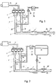
Fig. 1 shows a first option, which is not part of the present invention, -
Fig.2 shows a second option, which is provided according to the teachings of the present invention and can be combined with the features offigure 1 ; -
Figures 3 and 4 discloses two exemplary combinations of the schemes offigures 1 and 2 . - The same reference numerals and letters in the figures designate the same or functionally equivalent parts. According to the present invention, the term "second element" does not imply the presence of a "first element", first, second, etc.. are used only as labels for improving the clarity of the description and they should not be interpreted in a limiting way.
- Example embodiments are provided so that this disclosure will be thorough, and will fully convey the scope to those who are skilled in the art. Numerous specific details are set forth such as examples of specific components, devices, and methods, to provide a thorough understanding of embodiments of the present disclosure. It will be apparent to those skilled in the art that specific details need not be employed, that example embodiments may be embodied in many different forms and that neither should be construed to limit the scope of the disclosure. In some example embodiments, well-known processes, well-known device structures, and well known technologies are not described in detail.
- According to the figures, a
combustion engine 1, such as a gasoline or diesel engine is provided with anintake 11 and one or more exhaust manifolds 2. - The intake is connected operatively with an
inlet line 12 provided with afilter box 14 suitable to filter the fresh air sucked by the internal combustion engine. - In the example, the engine implements two exhaust manifolds, however, one single manifold can be implemented to convey the exhaust gas produced by all the several cylinders defining the
internal combustion engine 1. - The after treatment system ATS includes for example a first
pollutants abatement device 3, a second 5 and athird abatement device 19. - At least a portion of the ATS, for example at least one of the pollutants abatement devices, is wrapped within a
jacket 22. Preferably, the entire ATS is wrapped by the jacket. When the internal combustion engine is turbocharged, the jacket can wrap also the turbine. Thus, the turbine is intended, by a gas path and thermal point of view, as a portion of the ATS. - In the examples, the ATS includes two initial portions 2, directly connected with the internal combustion engine, of the ATS, which convey in one single remaining portion 4, thus two
first abatement devices 3 are present in parallel on the initial portions. In the example, just one of the two first abatement devices is wrapped within the jacked 22. This means that the devices that deserve to be wrapped can be selected according to the circumstances. - The jacket is operatively connected to a
vacuum pump 24 through a first piping 7 at theport 23 of the jacket. - The jacket is sealed and capable to maintain the vacuum generated by the vacuum pump.
- An on/off
valve 10 is arranged on the piping 7, upstream or downstream of the vacuum pump. - A button (not disclosed) is arranged on the dashboard. When the driver supposes to leave the vehicle shut-off for a long period, after he has shut-off the engine, he/she can push such button to activate the thermal management function according to the present invention.
- The vacuum pump can be activated immediately after the button pressing or only when the ATS temperature is under a predetermined temperature threshold, because, at high temperature some portions of the metal sheets defining the ATS canning of the abatement devices can be damaged by the vacuum.
- The expression "long period" should be understood according to the circumstances. For example, in extreme environment conditions, such as during winter with temperatures lower than 20-30 °C under 0°C, three hours can be considered as a "long period".
- According to the option of
figure 1 , after thevacuum pump 24 has reached a predetermined vacuum pressure within the jacket, thevalve 10 is operated into close operation to seal the piping 7 and then the vacuum pump is stopped. In this way, a possible leakage through the vacuum pump is prevented. - After the internal combustion engine is re-started, with the thermal management function active, the
valve 10 is operated into open position to release the vacuum within the jacket, only after the ATS temperature has reached a predetermined temperature threshold, so as to prevent the above-mentioned damaging of the metal sheets. - Therefore, the vacuum is released only if really needed and can depend on the structural characteristics of the canning of the abatement devices defining the ATS.
- According to a second option, under the teachings of the invention, disclosed through
figure 2 , the ATS, similarly as infigure 1 , is provided of ajacket 22 enveloping at least a portion of the ATS. - The lower portion of the
jacket 22, in operating condition, is connected to a lower portion of a well-insulatedtank 30, at least through one piping 72 on which aliquid pump 25 is arranged. - A tank thermal insulation can be realized according to any known method.
- The
liquid pump 25 is suitable to move a thermal liquid from thejacket 22 to the well-insulatedtank 30. - According to one embodiment of the present option, air replaces, into the
jacket 22, the thermal liquid that is moved by thepump 25 into thetank 30. In particular, as shown infigure 2 , such air flows into thejacket 22 through the control of avalve 20, e.g. defined by an on-off valve. - According to the relative position of the
tank 30 and thejacket 22, the thermal liquid can move from thetank 30 into thejacket 22 by gravity, or it can be pumped by reversing theliquid pump 25. - In this situation (refilling of the space in the
jacket 22 by menas of the liquid from the tank 30), the air within thejacket 22 should be vented (e.g. discharged towards the outer environment or towards the tank 30), while a corresponding amount of air should replace, within thetank 30, the thermal liquid volume. Indeed, it is preferable that thetank 30 is closed. In any case, suitable venting valves, asvalve 31 described below, can be implemented to manage air sucking/venting. - According to the example of
figure 2 , the second (second does imply the presence of a first) piping 72 is connected to a lower portion of thetank 30, such that the thermal liquid can fall naturally (i.e. by gravity) within thejacket 22, while the air contained therein is being vented. Preferably, as mentioned above, afirst piping 71 connects an operatively upper portion of thejacket 22 with an upper portion or zone of thetank 30 and a first on/offvalve 20 is arranged thereon. - Once the
valve 20 is closed, the thermal liquid cannot enter into thejacket 22, because the gas herewith contained cannot reach the upper portion of thetank 30. According to this embodiment, between thetank 30 and thejacket 22, a closed circuit is realized. Therefore, instead of using air, a specific gas can be used as insulation, such as argon or the like. - Therefore, during cold nights, the driver can activate a thermal management function, in such a manner that a thermal insulation gas (e.g. air) moves within the jacket 22 (
valve 20 is opened), while warm thermal liquid is pumped into thetank 30; when the warm thermal liquid is replaced with gas in thejacket 22,valve 20 is closed and pump 25 is stopped. On the other hand, during engine operation, the thermal liquid is moved within thejacket 22. -
Figure 3 discloses one of several possible combinations of the two main options described throughfigures 1 and 2 . Here, with respect tofigure 2 , avacuum pump 24 is arranged on thefirst piping 71 and second on/offvalve 21 is arranged on thesecond piping 72. - When the driver activates the thermal management function, first and second on/off
valves liquid pump 25 from thejacket 22 to thetank 30. When all the liquid is replaced with gas in thejacket 22, second on/offvalve 21 closes andliquid pump 25 stops. Then,vacuum pump 24 is activated; afterwards, first on/offvalve 20 is closed andvacuum pump 24 stops. - When the engine is re-started, or after a certain period, if the thermal liquid has a temperature above a predetermined threshold, the on/off
valve 21 opens so as to immediately refill thejacket 22. Otherwise, the thermal liquid is introduced into thejacket 22 gradually, after the ATS has reached the above light-off temperature, in order to maintain the ATS close to said light-off temperature. - It is clear to the skilled person in the art, that metering valves can be implemented instead of the cheaper on/off valves.
- A suitable control unit can be implemented to control the
vacuum pump 24 and/or theliquid pump 25 and the neededvalves - Indeed, when the stored thermal liquid has a heat content that can be suitably exploited, the thermal liquid is introduced within the
jacket 22 at engine re-start or even before such re-start (i.e. in response to an event, e.g. the opening of a vehicle door, indicating to the control unit that the engine is about to be re-started). On the other hand, if the heat content is not relevant, the thermal liquid is introduced within thejacket 22 only after the ATS has reached the light-off temperature threshold. - Preferably, the heat content is indirectly measured through the measurement of the stored thermal liquid temperature.
- In addition, the heat content is judged as "useful" if the stored thermal liquid temperature is higher than the ATS temperature. It is clear that the efficiency of the heat exchange between the thermal liquid and the ATS should be considered during such judgment.
- When vacuum is realized within the
jacket 22, such vacuum is maintained as long as the canning can bears such depressurization during temperature increase, and in any case till the introduction of the thermal liquid into thejacket 22. - To introduce the thermal liquid within the
jacket 22, second on/offvalve 21 opens and, vacuum can be initially exploited to suck liquid from thetank 30. Then first on/offvalve 20 opens and the thermal liquid can pass within thejacket 22 by gravity and/or by suction and/or by the reverse activation of theliquid pump 25. -
Figure 4 discloses another possible embodiment of the invention. - Here, the
first piping 71 has a first end opening in thejacket 22, wrapping at least a portion of the ATS, and a second end, opposite to the first one, communicating with the environment. On thefirst piping 71, avacuum pump 24 and a first on/offvalve 20 is arranged to generate and maintain the vacuum when the thermal management function is active. - Here, the
second piping 72 communicates, at one end, with a lower portion of thejacket 22 and, at a second opposite end, with a lower portion of thetank 30. - On the
second piping 72, theliquid pump 25 and the second on/offvalve 21 are arranged. - An upper portion of the
tank 30 communicates with the environment through a ventingvalve 31. - When the driver pushes the button to activate or enable the thermal management function, first the liquid is moved from the
jacket 22 to thetank 30. Thus, both the on/offvalves liquid pump 25 causes the movement of the thermal liquid. - When the thermal liquid is completely moved to the
tank 30,second valve 21 closes andliquid pumps 25 stops. Then,vacuum pump 24 is activated till a predetermined vacuum pressure. Then, first on/offvalve 20 closes andvacuum pump 24 stops. - The venting
valve 31 permits to vent the air from thetank 30. On the other hand, when the thermal liquid is pumped within thejacket 22, the ventingvalve 31 permits air to replace the volume of thermal liquid moved to thejacket 22. The ventingvalve 31 can be a spring loaded valve or can be an electric-controllable valve. In this second case, the motion by gravity of the thermal liquid from thetank 30 to thejacket 22 is simplified. - On the other hand, when the engine is re-started, the same steps disclosed for the example of
figure 3 are carried out. - According to a preferred embodiment of the invention, the thermal liquid coincides with engine water, or engine cooling liquid, and the
jacket 22 is connectable with the engine cooling circuit, such that when the driver opens the vehicle, the engine water is moved, though a dedicated circuit, from thetank 30 within the engine cooling circuit. Then, the thermal management of the ATS is carried out as described above. - Engine re-start is inhibited as long as the moving of the engine liquid from the
tank 30 to the engine cooling circuit is not complete. - Many changes, modifications, variations and other uses and applications of the subject invention will become apparent to those skilled in the art after considering the specification and the accompanying drawings which disclose preferred embodiments thereof as described in the appended claims.
- The features disclosed in the prior art background are introduced only in order to better understand the invention and not as a declaration about the existence of known prior art. In addition, said features define the context of the present invention, thus such features shall be considered in common with the detailed description.
- Further implementation details will not be described, as the man skilled in the art is able to carry out the invention starting from the teaching of the above description.
Claims (14)
- System for thermal management of an After Treatment System (ATS), the ATS being conceived to convey and purify exhaust gas produced by an internal combustion engine (1), the system comprising:- a jacket (22) wrapping at least a portion of said ATS,- an insulated tank (30) suitable to store a thermal liquid,- moving means (72,25,21,31) for moving said thermal liquid between said jacket (22) and said insulated tank (30), and- control means configured to control said moving means• to introduce said thermal liquid in said jacket (22), so as to exchange heat between the thermal liquid and said at least a portion of the ATS when the engine is operative, and• to store said thermal liquid in said insulated tank (30) when the engine is shut-off in order to store its heat content.
- System according to claim 1, wherein said control means comprise a control unit configured to activate and/or enable a thermal management function comprising an activation of said moving means to move the thermal liquid into said insulated tank (30) when said engine is detected as off and a switch or button is manipulated or pressed.
- System according to claim 2, wherein the thermal management function consists in:- the activation of said moving means to move the thermal liquid into said insulated tank (30) and- afterwards, an activation of vacuum means (24,20) for generating a vacuum in said jacket (22) .
- System according to claim 2 or 3, wherein said control unit is configured to check whether said internal combustion engine is off before enabling said thermal management function.
- System according to claim 2 or 3, wherein said control unit is configured to monitor a state condition of said internal combustion engine; when the thermal management function is active and the internal combustion engine is switched on, the control unit is configured to:- measure a liquid temperature of said thermal liquid within said insulated tank (30) and measure an ATS temperature,- introduce said thermal liquid in said jacket (22) if the measured liquid temperature is higher than the measured ATS temperature,- monitor said ATS temperature and gradually introduce said thermal liquid into said jacket (22) when the ATS temperature becomes above an ATS light-off temperature, if the measured liquid temperature is lower than the measured ATS temperature.
- System according to claim 5, wherein the gradual introduction of the thermal liquid into said jacket (22) is carried out in order to maintain said ATS temperature as close as possible to said light-off temperature.
- System according to claim 3, wherein said vacuum means include a vacuum pump (24) connected with said jacket (22) through a first piping (71) and an on/off valve (20) arranged on the first piping (71), upstream or downstream of the vacuum pump (24) to maintain said vacuum.
- System according to anyone of previous claims, wherein said moving means include a second piping (72) connecting a lower portion of said jacket (22) with a lower portion of said insulated tank (30), and a liquid pump (25) arranged to move said thermal liquid from said jacket (22) to said insulated tank and vice versa.
- System according to claim 7, wherein said moving means include a second piping (72) connecting a lower portion of said jacket (22) with a lower portion of said insulated tank (30), and a liquid pump (25) arranged to move said thermal liquid from said jacket to said insulated tank and vice versa, and wherein said first piping (71) has a first end connected with an upper portion of said jacket (22) and a second opposite end connected to an upper portion of said insulated tank (30).
- System according to claim 8, wherein said moving means comprise a first piping (71) having a first end connected with an upper portion of said jacket (22) and a second opposite end connected to an upper portion of said insulated tank (30).
- System according to claim 9 or 10, wherein a closed circuit is realized among the jacket, the first piping, the insulated tank and the second piping, and wherein an insulating gas is present and wherein, when said liquid pump (25) moves the thermal liquid to the insulated tank (30), said insulating gas moves to the jacket (30) and vice versa.
- Assembly including an internal combustion engine and an after treatment system arranged to treat exhaust gas produced by the internal combustion engine, the assembly including the system for thermal management according to any one of claims 1 to 11.
- Assembly according to claim 12, wherein said thermal liquid coincides with an engine cooling liquid and the jacket is connectable with an engine cooling circuit such that, before internal combustion engine re-start, the engine cooling liquid is moved, though a dedicated circuit, from said insulated tank (30) within the engine cooling circuit.
- Method for thermal management of an after treatment system (ATS), wherein at least a portion of the ATS is enveloped by a jacket (22), the method comprising the steps of- introducing a thermal liquid in said jacket, so as to exchange heat between the thermal liquid and said at least a portion of the ATS when the engine is operative, and- storing said thermal liquid in an insulated tank (30) when the engine is shut-off in order to store its heat content.
Applications Claiming Priority (1)
| Application Number | Priority Date | Filing Date | Title |
|---|---|---|---|
| IT102018000010826A IT201800010826A1 (en) | 2018-12-05 | 2018-12-05 | SYSTEM FOR THE THERMAL MANAGEMENT OF AN EXHAUSTED GAS AFTER-TREATMENT SYSTEM |
Publications (2)
| Publication Number | Publication Date |
|---|---|
| EP3663553A1 true EP3663553A1 (en) | 2020-06-10 |
| EP3663553B1 EP3663553B1 (en) | 2025-02-19 |
Family
ID=65496931
Family Applications (1)
| Application Number | Title | Priority Date | Filing Date |
|---|---|---|---|
| EP19213964.0A Active EP3663553B1 (en) | 2018-12-05 | 2019-12-05 | System for thermal management of an after treatment system (ats) |
Country Status (2)
| Country | Link |
|---|---|
| EP (1) | EP3663553B1 (en) |
| IT (1) | IT201800010826A1 (en) |
Citations (5)
| Publication number | Priority date | Publication date | Assignee | Title |
|---|---|---|---|---|
| DE3537080C1 (en) * | 1985-10-18 | 1987-06-19 | Benteler Werke Ag | Exhaust pipe with built-in exhaust gas catalyst - and outer insulation coating contg. evacuated cavity with chamber filled with better alloy |
| DE19837509A1 (en) | 1998-08-19 | 2000-02-24 | Bayerische Motoren Werke Ag | Exhaust system for IC engine with catalytic converter has part exhaust gas storage volume with shut-off valve to maintain vacuum and under pressure pump for evacuation |
| DE102008061026A1 (en) * | 2007-12-14 | 2009-06-18 | GM Global Technology Operations, Inc., Detroit | Recovery of waste heat |
| DE102009027350A1 (en) * | 2008-08-06 | 2010-02-18 | Denso Corporation, Kariya-City | Exhaust treatment device for an internal combustion engine |
| EP2410149A2 (en) * | 2010-07-22 | 2012-01-25 | J. Eberspächer GmbH & Co. KG | Exhaust system |
-
2018
- 2018-12-05 IT IT102018000010826A patent/IT201800010826A1/en unknown
-
2019
- 2019-12-05 EP EP19213964.0A patent/EP3663553B1/en active Active
Patent Citations (5)
| Publication number | Priority date | Publication date | Assignee | Title |
|---|---|---|---|---|
| DE3537080C1 (en) * | 1985-10-18 | 1987-06-19 | Benteler Werke Ag | Exhaust pipe with built-in exhaust gas catalyst - and outer insulation coating contg. evacuated cavity with chamber filled with better alloy |
| DE19837509A1 (en) | 1998-08-19 | 2000-02-24 | Bayerische Motoren Werke Ag | Exhaust system for IC engine with catalytic converter has part exhaust gas storage volume with shut-off valve to maintain vacuum and under pressure pump for evacuation |
| DE102008061026A1 (en) * | 2007-12-14 | 2009-06-18 | GM Global Technology Operations, Inc., Detroit | Recovery of waste heat |
| DE102009027350A1 (en) * | 2008-08-06 | 2010-02-18 | Denso Corporation, Kariya-City | Exhaust treatment device for an internal combustion engine |
| EP2410149A2 (en) * | 2010-07-22 | 2012-01-25 | J. Eberspächer GmbH & Co. KG | Exhaust system |
Also Published As
| Publication number | Publication date |
|---|---|
| IT201800010826A1 (en) | 2020-06-05 |
| EP3663553B1 (en) | 2025-02-19 |
Similar Documents
| Publication | Publication Date | Title |
|---|---|---|
| EP2795076B1 (en) | Exhaust aftertreatment system and method for operating the system | |
| CN202946272U (en) | Engine | |
| RU131648U1 (en) | LIQUID REDUCER INJECTION SYSTEM | |
| US7966811B2 (en) | Exhaust treatment system having a diverter valve | |
| US7146969B2 (en) | Motor vehicle comprising an activated carbon filter and method for regenerating an activated carbon filter | |
| CN102822481A (en) | Regeneration assist calibration | |
| CN102770635A (en) | Regeneration assist transition period | |
| JP2015081541A (en) | Exhaust emission control device of internal combustion engine | |
| EP2784274B1 (en) | A power system comprising a turbocharger lubricating bypass passage | |
| CN108071455B (en) | Exhaust gas purification device of internal combustion engine and control method of exhaust gas purification device | |
| US9032710B2 (en) | Diesel dosing system for active diesel particulate filter regeneration | |
| EP3025036B1 (en) | Scr exhaust emission control system and method therefore, for filling the urea reducing agent after returning to the tank | |
| CN101614168A (en) | Be used to have the engine start control of the motor of hydrocarbon retaining system | |
| JP2016211486A (en) | Exhaust emission control system | |
| CN101614167A (en) | Hydrocarbon retaining system and extract system | |
| EP3663553B1 (en) | System for thermal management of an after treatment system (ats) | |
| CN102365449A (en) | Device and method for drying fuel, in particular for motor vehicles | |
| CN107476857A (en) | A kind of vehicle-mounted absorber of heat accumulating type | |
| JP2007154772A (en) | Control device for internal combustion engine | |
| CN101614165B (en) | Hydrocarbon retaining system configuration for an internal combustion engine | |
| EP3333386B1 (en) | Injector deposit dissolution system and method | |
| EP3631176B1 (en) | A method for controlling the temperature of a nox controlling component and an exhaust after treatment system | |
| JP5579040B2 (en) | Exhaust heat insulation device | |
| US20240141813A1 (en) | Exhaust gas aftertreatment device for internal combustion engine | |
| JP3775460B2 (en) | Exhaust gas purification device for internal combustion engine |
Legal Events
| Date | Code | Title | Description |
|---|---|---|---|
| PUAI | Public reference made under article 153(3) epc to a published international application that has entered the european phase |
Free format text: ORIGINAL CODE: 0009012 |
|
| STAA | Information on the status of an ep patent application or granted ep patent |
Free format text: STATUS: THE APPLICATION HAS BEEN PUBLISHED |
|
| AK | Designated contracting states |
Kind code of ref document: A1 Designated state(s): AL AT BE BG CH CY CZ DE DK EE ES FI FR GB GR HR HU IE IS IT LI LT LU LV MC MK MT NL NO PL PT RO RS SE SI SK SM TR |
|
| AX | Request for extension of the european patent |
Extension state: BA ME |
|
| STAA | Information on the status of an ep patent application or granted ep patent |
Free format text: STATUS: REQUEST FOR EXAMINATION WAS MADE |
|
| 17P | Request for examination filed |
Effective date: 20201209 |
|
| RBV | Designated contracting states (corrected) |
Designated state(s): AL AT BE BG CH CY CZ DE DK EE ES FI FR GB GR HR HU IE IS IT LI LT LU LV MC MK MT NL NO PL PT RO RS SE SI SK SM TR |
|
| STAA | Information on the status of an ep patent application or granted ep patent |
Free format text: STATUS: EXAMINATION IS IN PROGRESS |
|
| 17Q | First examination report despatched |
Effective date: 20210119 |
|
| GRAP | Despatch of communication of intention to grant a patent |
Free format text: ORIGINAL CODE: EPIDOSNIGR1 |
|
| STAA | Information on the status of an ep patent application or granted ep patent |
Free format text: STATUS: GRANT OF PATENT IS INTENDED |
|
| INTG | Intention to grant announced |
Effective date: 20240919 |
|
| P01 | Opt-out of the competence of the unified patent court (upc) registered |
Free format text: CASE NUMBER: APP_60587/2024 Effective date: 20241111 |
|
| GRAS | Grant fee paid |
Free format text: ORIGINAL CODE: EPIDOSNIGR3 |
|
| GRAA | (expected) grant |
Free format text: ORIGINAL CODE: 0009210 |
|
| STAA | Information on the status of an ep patent application or granted ep patent |
Free format text: STATUS: THE PATENT HAS BEEN GRANTED |
|
| AK | Designated contracting states |
Kind code of ref document: B1 Designated state(s): AL AT BE BG CH CY CZ DE DK EE ES FI FR GB GR HR HU IE IS IT LI LT LU LV MC MK MT NL NO PL PT RO RS SE SI SK SM TR |
|
| REG | Reference to a national code |
Ref country code: GB Ref legal event code: FG4D |
|
| REG | Reference to a national code |
Ref country code: CH Ref legal event code: EP |
|
| REG | Reference to a national code |
Ref country code: DE Ref legal event code: R096 Ref document number: 602019066100 Country of ref document: DE |
|
| REG | Reference to a national code |
Ref country code: IE Ref legal event code: FG4D |
|
| REG | Reference to a national code |
Ref country code: NL Ref legal event code: MP Effective date: 20250219 |
|
| PG25 | Lapsed in a contracting state [announced via postgrant information from national office to epo] |
Ref country code: RS Free format text: LAPSE BECAUSE OF FAILURE TO SUBMIT A TRANSLATION OF THE DESCRIPTION OR TO PAY THE FEE WITHIN THE PRESCRIBED TIME-LIMIT Effective date: 20250519 |
|
| PG25 | Lapsed in a contracting state [announced via postgrant information from national office to epo] |
Ref country code: FI Free format text: LAPSE BECAUSE OF FAILURE TO SUBMIT A TRANSLATION OF THE DESCRIPTION OR TO PAY THE FEE WITHIN THE PRESCRIBED TIME-LIMIT Effective date: 20250219 |
|
| PG25 | Lapsed in a contracting state [announced via postgrant information from national office to epo] |
Ref country code: PL Free format text: LAPSE BECAUSE OF FAILURE TO SUBMIT A TRANSLATION OF THE DESCRIPTION OR TO PAY THE FEE WITHIN THE PRESCRIBED TIME-LIMIT Effective date: 20250219 |
|
| PG25 | Lapsed in a contracting state [announced via postgrant information from national office to epo] |
Ref country code: ES Free format text: LAPSE BECAUSE OF FAILURE TO SUBMIT A TRANSLATION OF THE DESCRIPTION OR TO PAY THE FEE WITHIN THE PRESCRIBED TIME-LIMIT Effective date: 20250219 |
|
| REG | Reference to a national code |
Ref country code: LT Ref legal event code: MG9D |
|
| PG25 | Lapsed in a contracting state [announced via postgrant information from national office to epo] |
Ref country code: NO Free format text: LAPSE BECAUSE OF FAILURE TO SUBMIT A TRANSLATION OF THE DESCRIPTION OR TO PAY THE FEE WITHIN THE PRESCRIBED TIME-LIMIT Effective date: 20250519 Ref country code: IS Free format text: LAPSE BECAUSE OF FAILURE TO SUBMIT A TRANSLATION OF THE DESCRIPTION OR TO PAY THE FEE WITHIN THE PRESCRIBED TIME-LIMIT Effective date: 20250619 |
|
| PG25 | Lapsed in a contracting state [announced via postgrant information from national office to epo] |
Ref country code: NL Free format text: LAPSE BECAUSE OF FAILURE TO SUBMIT A TRANSLATION OF THE DESCRIPTION OR TO PAY THE FEE WITHIN THE PRESCRIBED TIME-LIMIT Effective date: 20250219 |
|
| PG25 | Lapsed in a contracting state [announced via postgrant information from national office to epo] |
Ref country code: HR Free format text: LAPSE BECAUSE OF FAILURE TO SUBMIT A TRANSLATION OF THE DESCRIPTION OR TO PAY THE FEE WITHIN THE PRESCRIBED TIME-LIMIT Effective date: 20250219 |
|
| PG25 | Lapsed in a contracting state [announced via postgrant information from national office to epo] |
Ref country code: LV Free format text: LAPSE BECAUSE OF FAILURE TO SUBMIT A TRANSLATION OF THE DESCRIPTION OR TO PAY THE FEE WITHIN THE PRESCRIBED TIME-LIMIT Effective date: 20250219 Ref country code: PT Free format text: LAPSE BECAUSE OF FAILURE TO SUBMIT A TRANSLATION OF THE DESCRIPTION OR TO PAY THE FEE WITHIN THE PRESCRIBED TIME-LIMIT Effective date: 20250620 |
|
| PG25 | Lapsed in a contracting state [announced via postgrant information from national office to epo] |
Ref country code: BG Free format text: LAPSE BECAUSE OF FAILURE TO SUBMIT A TRANSLATION OF THE DESCRIPTION OR TO PAY THE FEE WITHIN THE PRESCRIBED TIME-LIMIT Effective date: 20250219 Ref country code: GR Free format text: LAPSE BECAUSE OF FAILURE TO SUBMIT A TRANSLATION OF THE DESCRIPTION OR TO PAY THE FEE WITHIN THE PRESCRIBED TIME-LIMIT Effective date: 20250520 |
|
| REG | Reference to a national code |
Ref country code: AT Ref legal event code: MK05 Ref document number: 1768461 Country of ref document: AT Kind code of ref document: T Effective date: 20250219 |
|
| PG25 | Lapsed in a contracting state [announced via postgrant information from national office to epo] |
Ref country code: SE Free format text: LAPSE BECAUSE OF FAILURE TO SUBMIT A TRANSLATION OF THE DESCRIPTION OR TO PAY THE FEE WITHIN THE PRESCRIBED TIME-LIMIT Effective date: 20250219 |
|
| PG25 | Lapsed in a contracting state [announced via postgrant information from national office to epo] |
Ref country code: SM Free format text: LAPSE BECAUSE OF FAILURE TO SUBMIT A TRANSLATION OF THE DESCRIPTION OR TO PAY THE FEE WITHIN THE PRESCRIBED TIME-LIMIT Effective date: 20250219 |
|
| PG25 | Lapsed in a contracting state [announced via postgrant information from national office to epo] |
Ref country code: DK Free format text: LAPSE BECAUSE OF FAILURE TO SUBMIT A TRANSLATION OF THE DESCRIPTION OR TO PAY THE FEE WITHIN THE PRESCRIBED TIME-LIMIT Effective date: 20250219 |
|
| PG25 | Lapsed in a contracting state [announced via postgrant information from national office to epo] |
Ref country code: AT Free format text: LAPSE BECAUSE OF FAILURE TO SUBMIT A TRANSLATION OF THE DESCRIPTION OR TO PAY THE FEE WITHIN THE PRESCRIBED TIME-LIMIT Effective date: 20250219 |
|
| PG25 | Lapsed in a contracting state [announced via postgrant information from national office to epo] |
Ref country code: EE Free format text: LAPSE BECAUSE OF FAILURE TO SUBMIT A TRANSLATION OF THE DESCRIPTION OR TO PAY THE FEE WITHIN THE PRESCRIBED TIME-LIMIT Effective date: 20250219 Ref country code: CZ Free format text: LAPSE BECAUSE OF FAILURE TO SUBMIT A TRANSLATION OF THE DESCRIPTION OR TO PAY THE FEE WITHIN THE PRESCRIBED TIME-LIMIT Effective date: 20250219 |
|
| PG25 | Lapsed in a contracting state [announced via postgrant information from national office to epo] |
Ref country code: RO Free format text: LAPSE BECAUSE OF FAILURE TO SUBMIT A TRANSLATION OF THE DESCRIPTION OR TO PAY THE FEE WITHIN THE PRESCRIBED TIME-LIMIT Effective date: 20250219 |
|
| PG25 | Lapsed in a contracting state [announced via postgrant information from national office to epo] |
Ref country code: SK Free format text: LAPSE BECAUSE OF FAILURE TO SUBMIT A TRANSLATION OF THE DESCRIPTION OR TO PAY THE FEE WITHIN THE PRESCRIBED TIME-LIMIT Effective date: 20250219 |
|
| REG | Reference to a national code |
Ref country code: DE Ref legal event code: R097 Ref document number: 602019066100 Country of ref document: DE |
|
| PLBE | No opposition filed within time limit |
Free format text: ORIGINAL CODE: 0009261 |
|
| STAA | Information on the status of an ep patent application or granted ep patent |
Free format text: STATUS: NO OPPOSITION FILED WITHIN TIME LIMIT |
|
| PGFP | Annual fee paid to national office [announced via postgrant information from national office to epo] |
Ref country code: IT Payment date: 20251119 Year of fee payment: 7 |
|
| PGFP | Annual fee paid to national office [announced via postgrant information from national office to epo] |
Ref country code: FR Payment date: 20251223 Year of fee payment: 7 |
|
| 26N | No opposition filed |
Effective date: 20251120 |
|
| PGFP | Annual fee paid to national office [announced via postgrant information from national office to epo] |
Ref country code: DE Payment date: 20251229 Year of fee payment: 7 |