EP3663209A1 - Aircraft system and method for airborne wildlife deterence - Google Patents
Aircraft system and method for airborne wildlife deterence Download PDFInfo
- Publication number
- EP3663209A1 EP3663209A1 EP19213350.2A EP19213350A EP3663209A1 EP 3663209 A1 EP3663209 A1 EP 3663209A1 EP 19213350 A EP19213350 A EP 19213350A EP 3663209 A1 EP3663209 A1 EP 3663209A1
- Authority
- EP
- European Patent Office
- Prior art keywords
- light
- aircraft
- landing gear
- gear assembly
- airborne
- Prior art date
- Legal status (The legal status is an assumption and is not a legal conclusion. Google has not performed a legal analysis and makes no representation as to the accuracy of the status listed.)
- Ceased
Links
- 238000000034 method Methods 0.000 title claims description 16
- 230000000712 assembly Effects 0.000 claims description 16
- 238000000429 assembly Methods 0.000 claims description 16
- 241000894007 species Species 0.000 description 15
- 241000271566 Aves Species 0.000 description 2
- 241000272517 Anseriformes Species 0.000 description 1
- 241000272161 Charadriiformes Species 0.000 description 1
- 241000288673 Chiroptera Species 0.000 description 1
- 230000008878 coupling Effects 0.000 description 1
- 238000010168 coupling process Methods 0.000 description 1
- 238000005859 coupling reaction Methods 0.000 description 1
- 238000010586 diagram Methods 0.000 description 1
- 230000000694 effects Effects 0.000 description 1
- 230000000007 visual effect Effects 0.000 description 1
Images



Classifications
-
- B—PERFORMING OPERATIONS; TRANSPORTING
- B64—AIRCRAFT; AVIATION; COSMONAUTICS
- B64D—EQUIPMENT FOR FITTING IN OR TO AIRCRAFT; FLIGHT SUITS; PARACHUTES; ARRANGEMENT OR MOUNTING OF POWER PLANTS OR PROPULSION TRANSMISSIONS IN AIRCRAFT
- B64D47/00—Equipment not otherwise provided for
- B64D47/02—Arrangements or adaptations of signal or lighting devices
- B64D47/06—Arrangements or adaptations of signal or lighting devices for indicating aircraft presence
-
- A—HUMAN NECESSITIES
- A01—AGRICULTURE; FORESTRY; ANIMAL HUSBANDRY; HUNTING; TRAPPING; FISHING
- A01M—CATCHING, TRAPPING OR SCARING OF ANIMALS; APPARATUS FOR THE DESTRUCTION OF NOXIOUS ANIMALS OR NOXIOUS PLANTS
- A01M29/00—Scaring or repelling devices, e.g. bird-scaring apparatus
- A01M29/06—Scaring or repelling devices, e.g. bird-scaring apparatus using visual means, e.g. scarecrows, moving elements, specific shapes, patterns or the like
- A01M29/10—Scaring or repelling devices, e.g. bird-scaring apparatus using visual means, e.g. scarecrows, moving elements, specific shapes, patterns or the like using light sources, e.g. lasers or flashing lights
-
- B—PERFORMING OPERATIONS; TRANSPORTING
- B64—AIRCRAFT; AVIATION; COSMONAUTICS
- B64D—EQUIPMENT FOR FITTING IN OR TO AIRCRAFT; FLIGHT SUITS; PARACHUTES; ARRANGEMENT OR MOUNTING OF POWER PLANTS OR PROPULSION TRANSMISSIONS IN AIRCRAFT
- B64D45/00—Aircraft indicators or protectors not otherwise provided for
-
- B—PERFORMING OPERATIONS; TRANSPORTING
- B64—AIRCRAFT; AVIATION; COSMONAUTICS
- B64C—AEROPLANES; HELICOPTERS
- B64C25/00—Alighting gear
- B64C25/001—Devices not provided for in the groups B64C25/02 - B64C25/68
-
- B—PERFORMING OPERATIONS; TRANSPORTING
- B64—AIRCRAFT; AVIATION; COSMONAUTICS
- B64C—AEROPLANES; HELICOPTERS
- B64C25/00—Alighting gear
- B64C25/02—Undercarriages
-
- B—PERFORMING OPERATIONS; TRANSPORTING
- B64—AIRCRAFT; AVIATION; COSMONAUTICS
- B64D—EQUIPMENT FOR FITTING IN OR TO AIRCRAFT; FLIGHT SUITS; PARACHUTES; ARRANGEMENT OR MOUNTING OF POWER PLANTS OR PROPULSION TRANSMISSIONS IN AIRCRAFT
- B64D45/00—Aircraft indicators or protectors not otherwise provided for
- B64D2045/0095—Devices specially adapted to avoid bird strike
-
- B—PERFORMING OPERATIONS; TRANSPORTING
- B64—AIRCRAFT; AVIATION; COSMONAUTICS
- B64D—EQUIPMENT FOR FITTING IN OR TO AIRCRAFT; FLIGHT SUITS; PARACHUTES; ARRANGEMENT OR MOUNTING OF POWER PLANTS OR PROPULSION TRANSMISSIONS IN AIRCRAFT
- B64D2203/00—Aircraft or airfield lights using LEDs
Definitions
- This disclosure relates generally to aircraft lighting systems, and more particularly to wildlife deterrence systems.
- Aircraft collisions with airborne wildlife i.e., bird strikes
- airborne wildlife i.e., bird strikes
- take-off and landing are an increasingly common occurrence and present an appreciable risk of damage to aircraft components (e.g., aircraft engines).
- aircraft components e.g., aircraft engines.
- Quieter aircraft are more difficult for airborne wildlife to detect.
- avoidance by airborne wildlife is more difficult because the wildlife may have less time to clear the flight path of the oncoming aircraft.
- a lighting system for an aircraft includes at least one light mounted on at least one landing gear assembly of the aircraft.
- the at least one light is configured to emit ultraviolet light when the at least one landing gear assembly is in a lowered condition.
- the at least one light may emit the ultraviolet light at a predetermined wavelength and frequency.
- the predetermined wavelength and frequency may be an airborne wildlife deterrence wavelength and frequency.
- the airborne wildlife deterrence wavelength and frequency may be configured to deter at least one predetermined airborne species.
- the at least one light may emit the ultraviolet light during a take-off or landing operation.
- the at least one light may be configured to direct the ultraviolet light toward a flight path vector of the aircraft when the aircraft has a non-zero angle of attack.
- the ultraviolet light emitted by the at least one light may be unobstructed by the aircraft between the at least one light and the flight path vector.
- the ultraviolet light emitted by the at least one light may be non-visible to humans.
- the at least one landing gear assembly may be a plurality of landing gear assemblies. Each landing gear assembly of the plurality of landing gear assemblies may include the at least one light.
- the at least one light of each landing gear assembly of the plurality of landing gear assemblies may direct the ultraviolet light in a different direction than each other of the at least one light of each other landing gear assembly of the plurality of landing gear assemblies.
- the at least one light may be a plurality of lights.
- a first at least one light of the plurality of lights may have a first predetermined wavelength and frequency configured to deter a first predetermined airborne wildlife species and a second at least one light of the plurality of lights may have a second predetermined wavelength and frequency, different than the first predetermined wavelength and frequency, and configured to deter a second predetermined airborne wildlife species.
- a method for operating a lighting system for an aircraft is disclosed.
- An ultraviolet light is emitted with at least one light mounted on at least one landing gear assembly.
- the ultraviolet light is directed toward a flight path vector of the aircraft.
- the aircraft has a non-zero angle of attack.
- the ultraviolet light emitted by the at least one light is unobstructed by the aircraft between the at least one light and the flight path vector.
- the at least one light may emit the ultraviolet light during a take-off or landing operation.
- the at least one light may emit the ultraviolet light when the landing gear assembly is in a lowered condition.
- an aircraft includes at least one landing gear assembly and at least one light mounted on the at least one landing gear assembly.
- the at least one light is configured to emit ultraviolet light.
- the at least one light is configured to direct the ultraviolet light toward a flight path vector of the aircraft when the aircraft has a non-zero angle of attack.
- the at least one light may emit the ultraviolet light at a predetermined wavelength and frequency.
- the landing gear assembly may include a plurality of landing gear assemblies. Each landing gear assembly of the plurality of landing gear assemblies may include at least one light.
- the at least one light of each landing gear assembly of the plurality of landing gear assemblies may direct the ultraviolet light in a different direction than each other of the at least one light of each other landing gear assembly of the plurality of landing gear assemblies.
- the at least one light may emit the ultraviolet light during a take-off or landing operation.
- the ultraviolet light emitted by the at least one light may be unobstructed by the aircraft between the at least one light and the flight path vector.
- UV light may be light having a wavelength in the range of 10-400 nm. In various embodiments, light in the range of 300-400 nm may be most useful for deterring airborne species. Of course, the effectiveness of the particular wavelength will vary between species and so UV light over the broader range (10-400 nm) may be used in the invention.
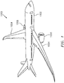
- the aircraft 1000 includes a fuselage 1002, wings 1004, and gas turbine engines 1006.
- One or more of the fuselage 1002 and the wings 1004 includes at least one landing gear assembly 10. It is noted that while the aircraft 1000 depicted in FIG. 1 is a commercial fixed-wing aircraft, in other aspects, the aircraft may be any other suitable aircraft, for example, a rotary-wing aircraft.
- the at least one landing gear assembly 10 is illustrated.
- one or more of the fuselage 1002 and the wings 1004 of the aircraft 1000 may include the at least one landing gear assembly 10.
- the at least one landing gear assembly 10 may be retractably disposed within the fuselage 1002 and/or the wings 1004.
- the at least one landing gear assembly 10 may be positioned in a "lowered condition" (i.e., fully or partially extended) during, for example, ground operations, take-off, and just prior to landing.
- the at least one landing gear assembly 10 may be retracted (i.e., raised) during flight to promote improved aerodynamic qualities of the aircraft 1000.
- the at least one landing gear assembly 10 may be retracted into the fuselage 1002 and/or the wings 1004.
- the at least one landing gear assembly 10 may be configured as a fixed landing gear assembly, a skid, or any other suitable landing gear assembly.
- the at least one landing gear assembly 10 includes at least one light 12.
- the at least one light 12 is configured to emit ultraviolet (UV) light 14 (e.g., light having a wavelength of approximately 10-400 nanometers (nm)).
- the at least one light 12 may be any suitable light configured to emit UV light 14 such as, for example, incandescent lights, LED lights, gas-discharge lights, lasers, etc.
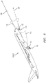
- the at least one light 12 may generally direct the UV light 14 toward a flight path vector 22 (see FIG. 6 ) of the aircraft 1000 thereby deterring airborne wildlife (i.e., birds, bats, etc.) from occupying the flight path vector 22 of the aircraft 1000.
- the location of the at least one light 12 on the at least one landing gear assembly 10 may provide improved aerodynamic qualities (e.g., reduced wind resistance) of the aircraft 1000 during normal aircraft operations, for example, when the at least one landing gear assembly 10 is in a raised condition during flight.
- the at least one light 12 may be disposed on other portions of the aircraft 1000, for example, the fuselage 1002, wings 1004, gas turbine engines 1006, etc.
- “deter” means to alert airborne wildlife to the presence of the approaching aircraft 1000 so as to provide the airborne wildlife with an increased opportunity to avoid collision with the aircraft 1000. It is noted that the bounds of the UV light 14 depicted in FIGS. 3 , 4 , and 6 are provided for ease of understanding. The breadth and range of the UV light 14 should not be understood to be limited as depicted.
- UV light 14 may be increased with respect to airborne wildlife (i.e., the UV light 14 may alert the airborne wildlife to the presence of the approaching aircraft 1000). Increased visibility may provide the airborne wildlife greater opportunity to avoid collision with the aircraft 1000 by clearing the flight path vector 22 of the aircraft.
- the at least one light 12 may emit UV light 14 having a predetermined wavelength and/or frequency.
- the UV light 14 may have a predetermined wavelength and/or frequency corresponding to an airborne wildlife deterrence wavelength and/or frequency (i.e., the wavelength and/or frequency is selected for deterrence of airborne wildlife by, for example, achieving optimum visibility of the UV light 14 with respect to airborne wildlife).
- the airborne wildlife deterrence wavelength and/or frequency may be configured to deter at least one predetermined airborne wildlife species (e.g., geese, gulls, etc.).
- the wavelength and/or frequency of the UV light 14 may be selected for optimum visibility of the UV light 14 by the at least one airborne wildlife species, thereby improving deterrence of the at least one airborne wildlife species from the flight path vector 22 of the aircraft 1000.
- Configuration of the predetermined wavelength and/or frequency (e.g., the airborne wildlife deterrence wavelength and/or frequency) to deter at least one predetermined airborne wildlife species may be desirable, for example, where a particular airborne wildlife species is known to operate in a particular area (e.g., in the vicinity of a destination airport).
- said configuration of the predetermined wavelength and/or frequency may be desirable based on altitude, for example, where bird strikes by a particular airborne wildlife species are more common at a particular altitude while bird strikes by a different particular airborne wildlife species are more common at a different altitude.
- the predetermined wavelength and/or frequency of the UV light 14 emitted by the at least one light 12 may be adjusted based on the particular species of airborne wildlife most likely to strike the aircraft 1000.
- the at least one landing gear assembly 10 may be a plurality of landing gear assemblies 10 with each landing gear assembly of the plurality of landing gear assemblies 10 including at least one light 12.
- the at least one light 12 of each landing gear assembly of the plurality of landing gear assemblies 10 may direct the UV light 14 in a same direction or a different direction than each other of the at least one light 12 of each other landing gear assembly of the plurality of landing gear assemblies 10 (see, e.g., FIG. 4 ).
- the at least one light 12 may be a plurality of lights 12. Each light of the plurality of lights 12 may be configured to emit UV light 14 having the same wavelength and/or frequency. In some embodiments, a first at least one light of the plurality of lights 12 may emit UV light 14 having a first wavelength and/or frequency while a second at least one light of the plurality of lights 12 may emit UV light 14 having a second wavelength and/or frequency, different than the first wavelength and/or frequency. In some embodiments, the first wavelength and/or frequency may be configured to deter a first at least one predetermined airborne wildlife species while the second wavelength and/or frequency may be configured to deter a second at least one predetermined airborne wildlife species.
- FIG. 5 generally illustrates an aircraft 1000 having a non-zero angle of attack, for example, during a take-off or a landing operation.
- the aircraft 1000 includes a longitudinal axis 26 extending generally forward to aft through the fuselage 1002.
- a pitch angle 20 (i.e., attitude) of the aircraft 1000 is the angle between the longitudinal axis 26 and the horizon 16.
- a flight path vector 22 of the aircraft 1000 defines the actual direction of intended travel of the aircraft 1000.
- a flight path angle 18 of the aircraft 1000 is the angle between the flight path vector 22 and the horizon 16.
- the angular difference between the longitudinal axis 26 and the flight path vector 22 (if any) defines an angle of attack 24.
- Shadowing (i.e., obstruction) of the UV light 14 by the aircraft 1000, between the at least one light 12 and the flight path vector 22, may reduce the effectiveness of the UV light 14 in deterring airborne wildlife.
- components of the aircraft 1000 e.g., the fuselage 1002 or the engines 1006
- the location of the at least one light 12 on the at least one landing gear assembly 10 may reduce or prevent shadowing effects of the aircraft 1000 by providing a more direct line-of-sight between the at least one light 12 and the flight path vector 22 with respect to potentially obstructing surfaces of the aircraft 1000.
- Shadowing of the UV light 14 may be further reduced by directing the UV light 14 toward the flight path vector 22 of the aircraft 1000 when the aircraft has a non-zero angle of attack 24.
- the UV light 14 emitted by the at least one light 12 may be partially or completely unobstructed by the aircraft 1000 between the at least one light 12 and the flight path vector 22.
- the at least one light 12 may be activated or deactivated manually (e.g., by a pilot). For example, the at least one light 12 may be activated when the aircraft 1000 is proceeding to lower altitudes (e.g., below 3,000 meters), where the majority of bird strikes occur. Alternatively, in some embodiments, the at least one light 12 may be activated or deactivated automatically (e.g., by a control system) when the landing gear assembly 10 is in a lowered condition.
- FIG. 7 is a flow diagram of a method 70 for operating an aircraft lighting system.
- step 72 at least one landing gear assembly 10 is provided (see, e.g., FIG. 2 ).
- step 74 at least one light 12, mounted on the at least one landing gear assembly 10 is provided (see, e.g., FIG. 2 ).
- step 76 UV light 14 is emitted with the at least one light 12 (see, e.g., FIGS. 3 , 4 , and 6 ).
- the UV light 14 is directed toward a flight path vector 22 of the aircraft 1000 (see, e.g., FIG. 6 ).
Landscapes
- Life Sciences & Earth Sciences (AREA)
- Engineering & Computer Science (AREA)
- Aviation & Aerospace Engineering (AREA)
- Insects & Arthropods (AREA)
- Optics & Photonics (AREA)
- Birds (AREA)
- Physics & Mathematics (AREA)
- Pest Control & Pesticides (AREA)
- Wood Science & Technology (AREA)
- Zoology (AREA)
- Environmental Sciences (AREA)
- Illuminated Signs And Luminous Advertising (AREA)
- Non-Portable Lighting Devices Or Systems Thereof (AREA)
Abstract
Description
- This disclosure relates generally to aircraft lighting systems, and more particularly to wildlife deterrence systems.
- Aircraft collisions with airborne wildlife (i.e., bird strikes), particularly during take-off and landing, are an increasingly common occurrence and present an appreciable risk of damage to aircraft components (e.g., aircraft engines). As modern aircraft have become increasingly quiet, the risk of bird strikes has increased. Quieter aircraft are more difficult for airborne wildlife to detect. As a result, avoidance by airborne wildlife is more difficult because the wildlife may have less time to clear the flight path of the oncoming aircraft.
- According to an aspect of the present invention, a lighting system for an aircraft includes at least one light mounted on at least one landing gear assembly of the aircraft. The at least one light is configured to emit ultraviolet light when the at least one landing gear assembly is in a lowered condition.
- The at least one light may emit the ultraviolet light at a predetermined wavelength and frequency.
- The predetermined wavelength and frequency may be an airborne wildlife deterrence wavelength and frequency.
- The airborne wildlife deterrence wavelength and frequency may be configured to deter at least one predetermined airborne species.
- The at least one light may emit the ultraviolet light during a take-off or landing operation.
- The at least one light may be configured to direct the ultraviolet light toward a flight path vector of the aircraft when the aircraft has a non-zero angle of attack.
- The ultraviolet light emitted by the at least one light may be unobstructed by the aircraft between the at least one light and the flight path vector.
- The ultraviolet light emitted by the at least one light may be non-visible to humans.
- The at least one landing gear assembly may be a plurality of landing gear assemblies. Each landing gear assembly of the plurality of landing gear assemblies may include the at least one light.
- The at least one light of each landing gear assembly of the plurality of landing gear assemblies may direct the ultraviolet light in a different direction than each other of the at least one light of each other landing gear assembly of the plurality of landing gear assemblies.
- The at least one light may be a plurality of lights. A first at least one light of the plurality of lights may have a first predetermined wavelength and frequency configured to deter a first predetermined airborne wildlife species and a second at least one light of the plurality of lights may have a second predetermined wavelength and frequency, different than the first predetermined wavelength and frequency, and configured to deter a second predetermined airborne wildlife species.
- According to an aspect of the present invention, a method for operating a lighting system for an aircraft is disclosed. An ultraviolet light is emitted with at least one light mounted on at least one landing gear assembly. The ultraviolet light is directed toward a flight path vector of the aircraft. The aircraft has a non-zero angle of attack. The ultraviolet light emitted by the at least one light is unobstructed by the aircraft between the at least one light and the flight path vector.
- The at least one light may emit the ultraviolet light during a take-off or landing operation.
- The at least one light may emit the ultraviolet light when the landing gear assembly is in a lowered condition.
- According to an aspect of the present invention, an aircraft includes at least one landing gear assembly and at least one light mounted on the at least one landing gear assembly. The at least one light is configured to emit ultraviolet light. The at least one light is configured to direct the ultraviolet light toward a flight path vector of the aircraft when the aircraft has a non-zero angle of attack.
- The at least one light may emit the ultraviolet light at a predetermined wavelength and frequency.
- The landing gear assembly may include a plurality of landing gear assemblies. Each landing gear assembly of the plurality of landing gear assemblies may include at least one light.
- The at least one light of each landing gear assembly of the plurality of landing gear assemblies may direct the ultraviolet light in a different direction than each other of the at least one light of each other landing gear assembly of the plurality of landing gear assemblies.
- The at least one light may emit the ultraviolet light during a take-off or landing operation.
- The ultraviolet light emitted by the at least one light may be unobstructed by the aircraft between the at least one light and the flight path vector.
- As used herein, UV light may be light having a wavelength in the range of 10-400 nm. In various embodiments, light in the range of 300-400 nm may be most useful for deterring airborne species. Of course, the effectiveness of the particular wavelength will vary between species and so UV light over the broader range (10-400 nm) may be used in the invention.
- The present disclosure, and all its aspects, embodiments and advantages associated therewith will become more readily apparent in view of the detailed description provided below, including the accompanying drawings.
-
-
FIG. 1 is a perspective view of an aircraft. -
FIG. 2 is a side view of an exemplary landing gear assembly. -
FIG. 3 is a side view of an aircraft with the exemplary landing gear assembly ofFIG. 2 . -
FIG. 4 is a cross-sectional, top view of the aircraft ofFIG. 3 . -
FIG. 5 is a side view of an aircraft having a non-zero angle of attack. -
FIG. 6 is a side view of the aircraft ofFIG. 3 having a non-zero angle of attack. -
FIG. 7 is a method of operating a lighting system for an aircraft. - It is noted that various connections are set forth between elements in the following description and in the drawings. It is noted that these connections are general and, unless specified otherwise, may be direct or indirect and that this specification is not intended to be limiting in this respect. A coupling between two or more entities may refer to a direct connection or an indirect connection. An indirect connection may incorporate one or more intervening entities. It is further noted that various method or process steps for embodiments of the present disclosure are described in the following description and drawings. The description may present the method and/or process steps as a particular sequence. However, to the extent that the method or process does not rely on the particular order of steps set forth herein, the method or process should not be limited to the particular sequence of steps described. As one of ordinary skill in the art would appreciate, other sequences of steps may be possible. Therefore, the particular order of the steps set forth in the description should not be construed as a limitation.
- Referring to
FIGS. 1 and2 , anaircraft 1000 is generally illustrated. Theaircraft 1000 includes afuselage 1002,wings 1004, andgas turbine engines 1006. One or more of thefuselage 1002 and thewings 1004 includes at least onelanding gear assembly 10. It is noted that while theaircraft 1000 depicted inFIG. 1 is a commercial fixed-wing aircraft, in other aspects, the aircraft may be any other suitable aircraft, for example, a rotary-wing aircraft. - Referring to
FIG. 2 , the at least onelanding gear assembly 10 is illustrated. As previously discussed, one or more of thefuselage 1002 and thewings 1004 of theaircraft 1000 may include the at least onelanding gear assembly 10. For example, in some embodiments, the at least onelanding gear assembly 10 may be retractably disposed within thefuselage 1002 and/or thewings 1004. As one of ordinary skill in the art will appreciate, the at least onelanding gear assembly 10 may be positioned in a "lowered condition" (i.e., fully or partially extended) during, for example, ground operations, take-off, and just prior to landing. The at least onelanding gear assembly 10 may be retracted (i.e., raised) during flight to promote improved aerodynamic qualities of theaircraft 1000. For example, the at least onelanding gear assembly 10 may be retracted into thefuselage 1002 and/or thewings 1004. In other embodiments, the at least onelanding gear assembly 10 may be configured as a fixed landing gear assembly, a skid, or any other suitable landing gear assembly. - Referring to
FIGS. 2-4 , the at least onelanding gear assembly 10 includes at least onelight 12. The at least one light 12 is configured to emit ultraviolet (UV) light 14 (e.g., light having a wavelength of approximately 10-400 nanometers (nm)). The at least one light 12 may be any suitable light configured to emitUV light 14 such as, for example, incandescent lights, LED lights, gas-discharge lights, lasers, etc. As will be discussed in further detail, the at least one light 12 may generally direct theUV light 14 toward a flight path vector 22 (seeFIG. 6 ) of theaircraft 1000 thereby deterring airborne wildlife (i.e., birds, bats, etc.) from occupying theflight path vector 22 of theaircraft 1000. The location of the at least one light 12 on the at least onelanding gear assembly 10 may provide improved aerodynamic qualities (e.g., reduced wind resistance) of theaircraft 1000 during normal aircraft operations, for example, when the at least onelanding gear assembly 10 is in a raised condition during flight. In some embodiments, however, the at least one light 12 may be disposed on other portions of theaircraft 1000, for example, thefuselage 1002,wings 1004,gas turbine engines 1006, etc. As used herein, "deter" means to alert airborne wildlife to the presence of the approachingaircraft 1000 so as to provide the airborne wildlife with an increased opportunity to avoid collision with theaircraft 1000. It is noted that the bounds of theUV light 14 depicted inFIGS. 3 ,4 , and6 are provided for ease of understanding. The breadth and range of theUV light 14 should not be understood to be limited as depicted. - Visual capabilities of airborne wildlife (e.g., birds) may permit said airborne wildlife to visually perceive
UV light 14 that would generally be non-visible to humans. Thus, by emitting and/or pulsingUV light 14, the visibility of an aircraft (e.g., aircraft 1000) may be increased with respect to airborne wildlife (i.e., theUV light 14 may alert the airborne wildlife to the presence of the approaching aircraft 1000). Increased visibility may provide the airborne wildlife greater opportunity to avoid collision with theaircraft 1000 by clearing theflight path vector 22 of the aircraft. - The at least one light 12 may emit
UV light 14 having a predetermined wavelength and/or frequency. For example, theUV light 14 may have a predetermined wavelength and/or frequency corresponding to an airborne wildlife deterrence wavelength and/or frequency (i.e., the wavelength and/or frequency is selected for deterrence of airborne wildlife by, for example, achieving optimum visibility of theUV light 14 with respect to airborne wildlife). In some embodiments, the airborne wildlife deterrence wavelength and/or frequency may be configured to deter at least one predetermined airborne wildlife species (e.g., geese, gulls, etc.). For example, the wavelength and/or frequency of theUV light 14 may be selected for optimum visibility of theUV light 14 by the at least one airborne wildlife species, thereby improving deterrence of the at least one airborne wildlife species from theflight path vector 22 of theaircraft 1000. - Configuration of the predetermined wavelength and/or frequency (e.g., the airborne wildlife deterrence wavelength and/or frequency) to deter at least one predetermined airborne wildlife species may be desirable, for example, where a particular airborne wildlife species is known to operate in a particular area (e.g., in the vicinity of a destination airport). For further example, said configuration of the predetermined wavelength and/or frequency may be desirable based on altitude, for example, where bird strikes by a particular airborne wildlife species are more common at a particular altitude while bird strikes by a different particular airborne wildlife species are more common at a different altitude. Accordingly, the predetermined wavelength and/or frequency of the
UV light 14 emitted by the at least one light 12 may be adjusted based on the particular species of airborne wildlife most likely to strike theaircraft 1000. - In some embodiments, the at least one
landing gear assembly 10 may be a plurality oflanding gear assemblies 10 with each landing gear assembly of the plurality oflanding gear assemblies 10 including at least onelight 12. The at least onelight 12 of each landing gear assembly of the plurality oflanding gear assemblies 10 may direct theUV light 14 in a same direction or a different direction than each other of the at least onelight 12 of each other landing gear assembly of the plurality of landing gear assemblies 10 (see, e.g.,FIG. 4 ). - In some embodiments, the at least one light 12 may be a plurality of
lights 12. Each light of the plurality oflights 12 may be configured to emitUV light 14 having the same wavelength and/or frequency. In some embodiments, a first at least one light of the plurality oflights 12 may emitUV light 14 having a first wavelength and/or frequency while a second at least one light of the plurality oflights 12 may emitUV light 14 having a second wavelength and/or frequency, different than the first wavelength and/or frequency. In some embodiments, the first wavelength and/or frequency may be configured to deter a first at least one predetermined airborne wildlife species while the second wavelength and/or frequency may be configured to deter a second at least one predetermined airborne wildlife species. -
FIG. 5 generally illustrates anaircraft 1000 having a non-zero angle of attack, for example, during a take-off or a landing operation. Theaircraft 1000 includes alongitudinal axis 26 extending generally forward to aft through thefuselage 1002. A pitch angle 20 (i.e., attitude) of theaircraft 1000 is the angle between thelongitudinal axis 26 and thehorizon 16. Aflight path vector 22 of theaircraft 1000 defines the actual direction of intended travel of theaircraft 1000. Aflight path angle 18 of theaircraft 1000 is the angle between theflight path vector 22 and thehorizon 16. The angular difference between thelongitudinal axis 26 and the flight path vector 22 (if any) defines an angle ofattack 24. - Shadowing (i.e., obstruction) of the
UV light 14 by theaircraft 1000, between the at least one light 12 and theflight path vector 22, may reduce the effectiveness of theUV light 14 in deterring airborne wildlife. For example, depending on the location of the at least one light 12 with respect to theaircraft 1000, components of the aircraft 1000 (e.g., thefuselage 1002 or the engines 1006) may obstruct some or all of the UV light from reaching theflight path vector 22. The location of the at least one light 12 on the at least onelanding gear assembly 10 may reduce or prevent shadowing effects of theaircraft 1000 by providing a more direct line-of-sight between the at least one light 12 and theflight path vector 22 with respect to potentially obstructing surfaces of theaircraft 1000. Shadowing of theUV light 14 may be further reduced by directing theUV light 14 toward theflight path vector 22 of theaircraft 1000 when the aircraft has a non-zero angle ofattack 24. For example, theUV light 14 emitted by the at least one light 12 may be partially or completely unobstructed by theaircraft 1000 between the at least one light 12 and theflight path vector 22. - In some embodiments, the at least one light 12 may be activated or deactivated manually (e.g., by a pilot). For example, the at least one light 12 may be activated when the
aircraft 1000 is proceeding to lower altitudes (e.g., below 3,000 meters), where the majority of bird strikes occur. Alternatively, in some embodiments, the at least one light 12 may be activated or deactivated automatically (e.g., by a control system) when thelanding gear assembly 10 is in a lowered condition. -
FIG. 7 is a flow diagram of amethod 70 for operating an aircraft lighting system. Instep 72, at least onelanding gear assembly 10 is provided (see, e.g.,FIG. 2 ). Instep 74, at least one light 12, mounted on the at least onelanding gear assembly 10 is provided (see, e.g.,FIG. 2 ). Instep 76,UV light 14 is emitted with the at least one light 12 (see, e.g.,FIGS. 3 ,4 , and6 ). Instep 78, theUV light 14 is directed toward aflight path vector 22 of the aircraft 1000 (see, e.g.,FIG. 6 ). - While various aspects of the present disclosure have been disclosed, it will be apparent to those of ordinary skill in the art that many more embodiments and implementations are possible within the scope of the present disclosure. For example, the present disclosure as described herein includes several aspects and embodiments that include particular features. Although these particular features may be described individually, it is within the scope of the present disclosure that some or all of these features may be combined with any one of the aspects and remain within the scope of the present disclosure. Accordingly, the present disclosure is not to be restricted except in light of the attached claims and their equivalents.
Claims (12)
- A lighting system for an aircraft (1000), the system comprising:at least one light (12) mountable on at least one landing gear assembly (10) of the aircraft (1000);wherein the at least one light (12) is configured to emit ultraviolet light when the at least one landing gear assembly (10) is in a lowered condition,
- The system of claim 1, wherein the at least one light (12) is configured to direct the ultraviolet light toward a flight path vector (22) of the aircraft (1000) when the aircraft (1000) has a non-zero angle of attack (24).
- An aircraft comprising:at least one landing gear assembly (10); andat least one light (12) mounted on the at least one landing gear assembly (10);wherein the at least one light (12) is configured to emit ultraviolet light;wherein the at least one light (12) is configured to direct the ultraviolet light toward a flight path vector (22) of the aircraft (1000) when the aircraft (1000) has a non-zero angle of attack.
- The system or aircraft of claim 2 or 3, wherein the ultraviolet light emitted by the at least one light (12) is unobstructed by the aircraft (1000) between the at least one light (12) and the flight path vector (22).
- The system or aircraft of any preceding claim, wherein the at least one light (12) is configured to emit the ultraviolet light at a predetermined wavelength and frequency,
wherein the predetermined wavelength and frequency is optionally an airborne wildlife deterrence wavelength and frequency,
wherein the airborne wildlife deterrence wavelength and frequency is optionally configured to deter at least one predetermined airborne species. - The system or aircraft of any preceding claim, wherein the at least one landing gear assembly (10) comprises a plurality of landing gear assemblies, each landing gear assembly (10) of the plurality of landing gear assemblies comprising at least one light (12),
wherein the at least one light (12) of each landing gear assembly (10) of the plurality of landing gear assemblies optionally directs the ultraviolet light in a different direction than each other of the at least one light (12) of each other landing gear assembly (10) of the plurality of landing gear assemblies. - The system or aircraft of any preceding claim, wherein the at least one light (12) is configured to emit the ultraviolet light during a take-off or landing operation.
- The system or aircraft of any preceding claim, wherein the ultraviolet light emitted by the at least one light is non-visible to humans.
- The system or aircraft of any preceding claim:wherein the at least one light is a plurality of lights (12); andwherein a first at least one light of the plurality of lights (12) has a first predetermined wavelength and frequency configured to deter a first predetermined airborne wildlife species and a second at least one light of the plurality of lights (12) has a second predetermined wavelength and frequency, different than the first predetermined wavelength and frequency, and configured to deter a second predetermined airborne wildlife species.
- A method for operating a lighting system for an aircraft (1000), the method comprising:emitting an ultraviolet light using at least one light (12) mounted on at least one landing gear assembly (10); anddirecting the ultraviolet light toward a flight path vector (22) of the aircraft (1000);wherein the aircraft (1000) has a non-zero angle of attack; andwherein the ultraviolet light emitted by the at least one light (12) is unobstructed by the aircraft (1000) between the at least one light (12) and the flight path vector (22).
- The method of claim 10, wherein the at least one light (12) emits the ultraviolet light during a take-off or landing operation.
- The method of claim 10 or 11, wherein the at least one light (12) emits the ultraviolet light when the landing gear assembly (10) is in a lowered condition.
Applications Claiming Priority (1)
| Application Number | Priority Date | Filing Date | Title |
|---|---|---|---|
| US16/207,728 US20200172265A1 (en) | 2018-12-03 | 2018-12-03 | Aircraft system and method for airborne wildlife deterence |
Publications (1)
| Publication Number | Publication Date |
|---|---|
| EP3663209A1 true EP3663209A1 (en) | 2020-06-10 |
Family
ID=68771381
Family Applications (1)
| Application Number | Title | Priority Date | Filing Date |
|---|---|---|---|
| EP19213350.2A Ceased EP3663209A1 (en) | 2018-12-03 | 2019-12-03 | Aircraft system and method for airborne wildlife deterence |
Country Status (2)
| Country | Link |
|---|---|
| US (1) | US20200172265A1 (en) |
| EP (1) | EP3663209A1 (en) |
Families Citing this family (2)
| Publication number | Priority date | Publication date | Assignee | Title |
|---|---|---|---|---|
| US12411240B2 (en) * | 2023-09-20 | 2025-09-09 | The Boeing Company | Aircraft flight path clearing light beams |
| US20260038379A1 (en) * | 2024-08-01 | 2026-02-05 | The Boeing Company | Nonuniform Laser Beam Scan Based Flight Path Clearing System |
Citations (5)
| Publication number | Priority date | Publication date | Assignee | Title |
|---|---|---|---|---|
| US20120069589A1 (en) * | 2010-09-22 | 2012-03-22 | Willeke Benjamin | Led landing light arrangement for an aircraft |
| US20160029615A1 (en) * | 2014-02-13 | 2016-02-04 | Government Of The United States, As Represented By The Secretary Of The Air Force | Airborne Bird Strike Countermeasure |
| US20170099828A1 (en) * | 2015-10-07 | 2017-04-13 | Lite Enterprises Inc. | Non-lethal wildlife deterrence aircraft lighting apparatus |
| US20180000062A1 (en) * | 2016-07-01 | 2018-01-04 | Maurice A. Khawam | Aircraft lighting system |
| US10150574B2 (en) * | 2015-07-22 | 2018-12-11 | The Boeing Company | Landing gear lights having multi-axis rotation |
-
2018
- 2018-12-03 US US16/207,728 patent/US20200172265A1/en not_active Abandoned
-
2019
- 2019-12-03 EP EP19213350.2A patent/EP3663209A1/en not_active Ceased
Patent Citations (5)
| Publication number | Priority date | Publication date | Assignee | Title |
|---|---|---|---|---|
| US20120069589A1 (en) * | 2010-09-22 | 2012-03-22 | Willeke Benjamin | Led landing light arrangement for an aircraft |
| US20160029615A1 (en) * | 2014-02-13 | 2016-02-04 | Government Of The United States, As Represented By The Secretary Of The Air Force | Airborne Bird Strike Countermeasure |
| US10150574B2 (en) * | 2015-07-22 | 2018-12-11 | The Boeing Company | Landing gear lights having multi-axis rotation |
| US20170099828A1 (en) * | 2015-10-07 | 2017-04-13 | Lite Enterprises Inc. | Non-lethal wildlife deterrence aircraft lighting apparatus |
| US20180000062A1 (en) * | 2016-07-01 | 2018-01-04 | Maurice A. Khawam | Aircraft lighting system |
Non-Patent Citations (1)
| Title |
|---|
| OLLE LIND ET AL: "Ultraviolet vision in birds: the importance of transparent eye media", BIOLOGICAL SCIENCES, vol. 281, no. 1774, 7 January 2014 (2014-01-07), pages 20132209, XP055683313, ISSN: 0962-8452, DOI: 10.1098/rspb.2013.2209 * |
Also Published As
| Publication number | Publication date |
|---|---|
| US20200172265A1 (en) | 2020-06-04 |
Similar Documents
| Publication | Publication Date | Title |
|---|---|---|
| US10351258B1 (en) | System for protecting aircraft against bird strikes | |
| CN107757936B (en) | Exterior aircraft light unit and method of alerting ground personnel | |
| WO2010023253A1 (en) | A bird collision avoidance system | |
| EP2855275B1 (en) | Lighting array for an aircraft | |
| US8164462B1 (en) | Geese chasing system | |
| EP3095641B1 (en) | Aircraft landing light unit, exterior aircraft lighting system and method of operating an aircraft landing light unit | |
| US7871455B1 (en) | Jet engine protection system | |
| US20180000062A1 (en) | Aircraft lighting system | |
| US20070023571A1 (en) | Quiet airplane configuration | |
| EP1753658A1 (en) | Positioning system, device, and method for in-flight refueling | |
| US10220959B2 (en) | Aircraft lighting system | |
| US20200172265A1 (en) | Aircraft system and method for airborne wildlife deterence | |
| US20190241278A1 (en) | Helicopter and window lights | |
| US11465773B2 (en) | Aircraft beacon light unit and set of aircraft beacon light units | |
| US6669357B2 (en) | Surface illumination system of an aircraft and like vehicles | |
| US10513349B2 (en) | Combined aircraft take-off and tower signal light unit and aircraft comprising the same | |
| US8245973B2 (en) | Methods and systems for improving aircraft visibility | |
| EP3118564B1 (en) | Method for protecting a vehicle against an attack by a laser beam | |
| US20160319743A1 (en) | Bird guard device | |
| US20220219834A1 (en) | Set of Exterior Aircraft Lights and Aircraft Comprising such a Set of Exterior Aircraft Lights | |
| CN219601606U (en) | Aircraft with a plurality of aircraft body | |
| US20260023174A1 (en) | Counter-bird aircraft system using a doppler detection device to alert pilots of an imminent bird strike threat | |
| US20250240858A1 (en) | Infrared / ultraviolet strobe device | |
| WO2007136262A1 (en) | Aircraft vehicle | |
| US20250093512A1 (en) | Aircraft Flight Path Clearing Light Beams |
Legal Events
| Date | Code | Title | Description |
|---|---|---|---|
| PUAI | Public reference made under article 153(3) epc to a published international application that has entered the european phase |
Free format text: ORIGINAL CODE: 0009012 |
|
| STAA | Information on the status of an ep patent application or granted ep patent |
Free format text: STATUS: THE APPLICATION HAS BEEN PUBLISHED |
|
| AK | Designated contracting states |
Kind code of ref document: A1 Designated state(s): AL AT BE BG CH CY CZ DE DK EE ES FI FR GB GR HR HU IE IS IT LI LT LU LV MC MK MT NL NO PL PT RO RS SE SI SK SM TR |
|
| AX | Request for extension of the european patent |
Extension state: BA ME |
|
| RIN1 | Information on inventor provided before grant (corrected) |
Inventor name: KESTLER, STEVEN M. Inventor name: UNG, ROGER Inventor name: COETZEE, BRANDON Inventor name: DELANEY, MAC P. |
|
| STAA | Information on the status of an ep patent application or granted ep patent |
Free format text: STATUS: REQUEST FOR EXAMINATION WAS MADE |
|
| 17P | Request for examination filed |
Effective date: 20201210 |
|
| RBV | Designated contracting states (corrected) |
Designated state(s): AL AT BE BG CH CY CZ DE DK EE ES FI FR GB GR HR HU IE IS IT LI LT LU LV MC MK MT NL NO PL PT RO RS SE SI SK SM TR |
|
| STAA | Information on the status of an ep patent application or granted ep patent |
Free format text: STATUS: EXAMINATION IS IN PROGRESS |
|
| 17Q | First examination report despatched |
Effective date: 20210511 |
|
| STAA | Information on the status of an ep patent application or granted ep patent |
Free format text: STATUS: THE APPLICATION HAS BEEN REFUSED |
|
| 18R | Application refused |
Effective date: 20240606 |