EP3663194A1 - Flight control cable sensor for an aircraft - Google Patents
Flight control cable sensor for an aircraft Download PDFInfo
- Publication number
- EP3663194A1 EP3663194A1 EP19210599.7A EP19210599A EP3663194A1 EP 3663194 A1 EP3663194 A1 EP 3663194A1 EP 19210599 A EP19210599 A EP 19210599A EP 3663194 A1 EP3663194 A1 EP 3663194A1
- Authority
- EP
- European Patent Office
- Prior art keywords
- connector
- flight control
- control cable
- flight
- force
- Prior art date
- Legal status (The legal status is an assumption and is not a legal conclusion. Google has not performed a legal analysis and makes no representation as to the accuracy of the status listed.)
- Granted
Links
Images




Classifications
-
- B—PERFORMING OPERATIONS; TRANSPORTING
- B64—AIRCRAFT; AVIATION; COSMONAUTICS
- B64C—AEROPLANES; HELICOPTERS
- B64C19/00—Aircraft control not otherwise provided for
-
- B—PERFORMING OPERATIONS; TRANSPORTING
- B64—AIRCRAFT; AVIATION; COSMONAUTICS
- B64C—AEROPLANES; HELICOPTERS
- B64C13/00—Control systems or transmitting systems for actuating flying-control surfaces, lift-increasing flaps, air brakes, or spoilers
- B64C13/24—Transmitting means
- B64C13/26—Transmitting means without power amplification or where power amplification is irrelevant
- B64C13/28—Transmitting means without power amplification or where power amplification is irrelevant mechanical
- B64C13/30—Transmitting means without power amplification or where power amplification is irrelevant mechanical using cable, chain, or rod mechanisms
-
- B—PERFORMING OPERATIONS; TRANSPORTING
- B64—AIRCRAFT; AVIATION; COSMONAUTICS
- B64D—EQUIPMENT FOR FITTING IN OR TO AIRCRAFT; FLIGHT SUITS; PARACHUTES; ARRANGEMENT OR MOUNTING OF POWER PLANTS OR PROPULSION TRANSMISSIONS IN AIRCRAFT
- B64D43/00—Arrangements or adaptations of instruments
-
- B—PERFORMING OPERATIONS; TRANSPORTING
- B64—AIRCRAFT; AVIATION; COSMONAUTICS
- B64D—EQUIPMENT FOR FITTING IN OR TO AIRCRAFT; FLIGHT SUITS; PARACHUTES; ARRANGEMENT OR MOUNTING OF POWER PLANTS OR PROPULSION TRANSMISSIONS IN AIRCRAFT
- B64D45/00—Aircraft indicators or protectors not otherwise provided for
- B64D45/0005—Devices specially adapted to indicate the position of a movable element of the aircraft, e.g. landing gear
-
- B—PERFORMING OPERATIONS; TRANSPORTING
- B64—AIRCRAFT; AVIATION; COSMONAUTICS
- B64F—GROUND OR AIRCRAFT-CARRIER-DECK INSTALLATIONS SPECIALLY ADAPTED FOR USE IN CONNECTION WITH AIRCRAFT; DESIGNING, MANUFACTURING, ASSEMBLING, CLEANING, MAINTAINING OR REPAIRING AIRCRAFT, NOT OTHERWISE PROVIDED FOR; HANDLING, TRANSPORTING, TESTING OR INSPECTING AIRCRAFT COMPONENTS, NOT OTHERWISE PROVIDED FOR
- B64F5/00—Designing, manufacturing, assembling, cleaning, maintaining or repairing aircraft, not otherwise provided for; Handling, transporting, testing or inspecting aircraft components, not otherwise provided for
- B64F5/60—Testing or inspecting aircraft components or systems
-
- G—PHYSICS
- G01—MEASURING; TESTING
- G01D—MEASURING NOT SPECIALLY ADAPTED FOR A SPECIFIC VARIABLE; ARRANGEMENTS FOR MEASURING TWO OR MORE VARIABLES NOT COVERED IN A SINGLE OTHER SUBCLASS; TARIFF METERING APPARATUS; MEASURING OR TESTING NOT OTHERWISE PROVIDED FOR
- G01D3/00—Indicating or recording apparatus with provision for the special purposes referred to in the subgroups
- G01D3/08—Indicating or recording apparatus with provision for the special purposes referred to in the subgroups with provision for safeguarding the apparatus, e.g. against abnormal operation, against breakdown
-
- G—PHYSICS
- G01—MEASURING; TESTING
- G01D—MEASURING NOT SPECIALLY ADAPTED FOR A SPECIFIC VARIABLE; ARRANGEMENTS FOR MEASURING TWO OR MORE VARIABLES NOT COVERED IN A SINGLE OTHER SUBCLASS; TARIFF METERING APPARATUS; MEASURING OR TESTING NOT OTHERWISE PROVIDED FOR
- G01D5/00—Mechanical means for transferring the output of a sensing member; Means for converting the output of a sensing member to another variable where the form or nature of the sensing member does not constrain the means for converting; Transducers not specially adapted for a specific variable
-
- G—PHYSICS
- G01—MEASURING; TESTING
- G01D—MEASURING NOT SPECIALLY ADAPTED FOR A SPECIFIC VARIABLE; ARRANGEMENTS FOR MEASURING TWO OR MORE VARIABLES NOT COVERED IN A SINGLE OTHER SUBCLASS; TARIFF METERING APPARATUS; MEASURING OR TESTING NOT OTHERWISE PROVIDED FOR
- G01D5/00—Mechanical means for transferring the output of a sensing member; Means for converting the output of a sensing member to another variable where the form or nature of the sensing member does not constrain the means for converting; Transducers not specially adapted for a specific variable
- G01D5/12—Mechanical means for transferring the output of a sensing member; Means for converting the output of a sensing member to another variable where the form or nature of the sensing member does not constrain the means for converting; Transducers not specially adapted for a specific variable using electric or magnetic means
-
- G—PHYSICS
- G01—MEASURING; TESTING
- G01D—MEASURING NOT SPECIALLY ADAPTED FOR A SPECIFIC VARIABLE; ARRANGEMENTS FOR MEASURING TWO OR MORE VARIABLES NOT COVERED IN A SINGLE OTHER SUBCLASS; TARIFF METERING APPARATUS; MEASURING OR TESTING NOT OTHERWISE PROVIDED FOR
- G01D5/00—Mechanical means for transferring the output of a sensing member; Means for converting the output of a sensing member to another variable where the form or nature of the sensing member does not constrain the means for converting; Transducers not specially adapted for a specific variable
- G01D5/12—Mechanical means for transferring the output of a sensing member; Means for converting the output of a sensing member to another variable where the form or nature of the sensing member does not constrain the means for converting; Transducers not specially adapted for a specific variable using electric or magnetic means
- G01D5/244—Mechanical means for transferring the output of a sensing member; Means for converting the output of a sensing member to another variable where the form or nature of the sensing member does not constrain the means for converting; Transducers not specially adapted for a specific variable using electric or magnetic means influencing characteristics of pulses or pulse trains; generating pulses or pulse trains
-
- G—PHYSICS
- G01—MEASURING; TESTING
- G01D—MEASURING NOT SPECIALLY ADAPTED FOR A SPECIFIC VARIABLE; ARRANGEMENTS FOR MEASURING TWO OR MORE VARIABLES NOT COVERED IN A SINGLE OTHER SUBCLASS; TARIFF METERING APPARATUS; MEASURING OR TESTING NOT OTHERWISE PROVIDED FOR
- G01D5/00—Mechanical means for transferring the output of a sensing member; Means for converting the output of a sensing member to another variable where the form or nature of the sensing member does not constrain the means for converting; Transducers not specially adapted for a specific variable
- G01D5/12—Mechanical means for transferring the output of a sensing member; Means for converting the output of a sensing member to another variable where the form or nature of the sensing member does not constrain the means for converting; Transducers not specially adapted for a specific variable using electric or magnetic means
- G01D5/244—Mechanical means for transferring the output of a sensing member; Means for converting the output of a sensing member to another variable where the form or nature of the sensing member does not constrain the means for converting; Transducers not specially adapted for a specific variable using electric or magnetic means influencing characteristics of pulses or pulse trains; generating pulses or pulse trains
- G01D5/24428—Error prevention
-
- G—PHYSICS
- G01—MEASURING; TESTING
- G01D—MEASURING NOT SPECIALLY ADAPTED FOR A SPECIFIC VARIABLE; ARRANGEMENTS FOR MEASURING TWO OR MORE VARIABLES NOT COVERED IN A SINGLE OTHER SUBCLASS; TARIFF METERING APPARATUS; MEASURING OR TESTING NOT OTHERWISE PROVIDED FOR
- G01D5/00—Mechanical means for transferring the output of a sensing member; Means for converting the output of a sensing member to another variable where the form or nature of the sensing member does not constrain the means for converting; Transducers not specially adapted for a specific variable
- G01D5/12—Mechanical means for transferring the output of a sensing member; Means for converting the output of a sensing member to another variable where the form or nature of the sensing member does not constrain the means for converting; Transducers not specially adapted for a specific variable using electric or magnetic means
- G01D5/244—Mechanical means for transferring the output of a sensing member; Means for converting the output of a sensing member to another variable where the form or nature of the sensing member does not constrain the means for converting; Transducers not specially adapted for a specific variable using electric or magnetic means influencing characteristics of pulses or pulse trains; generating pulses or pulse trains
- G01D5/24428—Error prevention
- G01D5/24433—Error prevention by mechanical means
-
- G—PHYSICS
- G01—MEASURING; TESTING
- G01D—MEASURING NOT SPECIALLY ADAPTED FOR A SPECIFIC VARIABLE; ARRANGEMENTS FOR MEASURING TWO OR MORE VARIABLES NOT COVERED IN A SINGLE OTHER SUBCLASS; TARIFF METERING APPARATUS; MEASURING OR TESTING NOT OTHERWISE PROVIDED FOR
- G01D5/00—Mechanical means for transferring the output of a sensing member; Means for converting the output of a sensing member to another variable where the form or nature of the sensing member does not constrain the means for converting; Transducers not specially adapted for a specific variable
- G01D5/12—Mechanical means for transferring the output of a sensing member; Means for converting the output of a sensing member to another variable where the form or nature of the sensing member does not constrain the means for converting; Transducers not specially adapted for a specific variable using electric or magnetic means
- G01D5/244—Mechanical means for transferring the output of a sensing member; Means for converting the output of a sensing member to another variable where the form or nature of the sensing member does not constrain the means for converting; Transducers not specially adapted for a specific variable using electric or magnetic means influencing characteristics of pulses or pulse trains; generating pulses or pulse trains
- G01D5/24428—Error prevention
- G01D5/24433—Error prevention by mechanical means
- G01D5/24438—Special design of the sensing element or scale
-
- G—PHYSICS
- G01—MEASURING; TESTING
- G01D—MEASURING NOT SPECIALLY ADAPTED FOR A SPECIFIC VARIABLE; ARRANGEMENTS FOR MEASURING TWO OR MORE VARIABLES NOT COVERED IN A SINGLE OTHER SUBCLASS; TARIFF METERING APPARATUS; MEASURING OR TESTING NOT OTHERWISE PROVIDED FOR
- G01D5/00—Mechanical means for transferring the output of a sensing member; Means for converting the output of a sensing member to another variable where the form or nature of the sensing member does not constrain the means for converting; Transducers not specially adapted for a specific variable
- G01D5/12—Mechanical means for transferring the output of a sensing member; Means for converting the output of a sensing member to another variable where the form or nature of the sensing member does not constrain the means for converting; Transducers not specially adapted for a specific variable using electric or magnetic means
- G01D5/244—Mechanical means for transferring the output of a sensing member; Means for converting the output of a sensing member to another variable where the form or nature of the sensing member does not constrain the means for converting; Transducers not specially adapted for a specific variable using electric or magnetic means influencing characteristics of pulses or pulse trains; generating pulses or pulse trains
- G01D5/24428—Error prevention
- G01D5/24433—Error prevention by mechanical means
- G01D5/24442—Error prevention by mechanical means by mounting means
Definitions
- This disclosure relates generally to aircraft, and more particularly to a flight control cable sensor for detecting actuation of a flight control cable of an aircraft.
- Flight control cables are used to mechanically actuate flight control surfaces of aircraft. Sensors are used to detect actuation of flight control cables. Sensed conditions from the sensors can be used to determine the position of the flight control surfaces. Some sensors for detecting actuation of flight control cables can negatively affect operation of the flight control cables if the sensors become disabled.
- the subject matter of the present application has been developed in response to the present state of the art, and in particular, in response to the shortcomings of conventional sensors for sensing flight control cables that have not yet been fully solved by currently available techniques. Accordingly, the subject matter of the present application has been developed to provide a flight control cable sensor, and associated systems and methods, that overcome at least some of the above-discussed shortcomings of prior art flight control cable sensors.
- the flight control cable sensor for detecting actuation of a flight control cable of an aircraft.
- the flight control cable sensor comprises a draw wire encoder, comprising an extendable-retractable wire.
- the flight control cable sensor further comprises a first connector, co-movably fixed to the extendable-retractable wire, and a second connector, co-movably fixable to the flight control cable and configured to removably co-movably engage the first connector up to a predetermined pull-off force.
- One of the first connector or the second connector comprises a magnet.
- An other of the first connector or the second connector is made of a ferromagnetic material magnetically attracted to the magnet.
- Removable co-movable engagement between the first connector and the second connector comprises magnetic engagement between the magnet and the ferromagnetic material.
- the predetermined pull-off force corresponds with a maximum magnetic force between the magnet and the ferromagnetic material.
- the second connector comprises a receptacle.
- the first connector is matingly receivable within the receptacle to removably co-movably engage the first connector and the second connector.
- example 4 of the present disclosure characterizes example 4 of the present disclosure, wherein example 4 also includes the subject matter according to example 3, above.
- example 5 of the present disclosure characterizes example 5 of the present disclosure, wherein example 5 also includes the subject matter according to example 4, above.
- the first connector comprises the magnet.
- the second connector is made of the ferromagnetic material magnetically attracted to the magnet.
- the first connector comprises a receptacle.
- the second connector is matingly receivable within the receptacle to removably co-movably engage the first connector and the second connector.
- the first connector comprises a first portion of a ball detent mechanism.
- the second connector comprises a second portion of the ball detent mechanism. Removable co-movable engagement between the first connector and the second connector comprises engagement between the first portion of the ball detent mechanism and the second portion of the ball detent mechanism.
- the predetermined pull-off force corresponds with a mechanical biasing force of the ball detent mechanism.
- the flight control sensor further comprises a carriage comprising a clamp, configured to non-movably fixedly clamp to the flight control cable, and the second connector.
- the second connector is coupled to the clamp.
- the draw wire encoder further comprises a spring-loaded reel about which a portion of the extendable-retractable wire is wound.
- the draw wire encoder also comprises a rotary encoder coupled to the spring-loaded reel and configured to detect extension and retraction of the extendable-retractable wire.
- the aircraft comprises a flight control cable comprising a first end and a second end opposite the first end.
- the aircraft additional comprises a flight control surface coupled to the first end of the flight control cable and a flight controller coupled to the second end of the flight control cable.
- the flight controller is operable to actuate the flight control surface by actuating the flight control cable.
- the aircraft further comprises a flight control cable sensor that comprises a draw wire encoder comprising an extendable-retractable wire, a first connector co-movably fixed to the extendable-retractable wire, and a second connector co-movably fixed to the flight control cable and removably co-movably engaged with the first connector up to a predetermined pull-off force.
- the draw wire encoder is communicatively coupled with the flight controller to deliver a sensed position of the flight control cable to the flight controller.
- the flight controller is configured to determine a status of the flight control cable sensor based at least partially on the sensed position of the flight control cable received from the draw wire encoder.
- the flight controller determines the status of the flight control cable sensor by comparing the sensed position of the flight control cable received from the draw wire encoder to an indication of a position of the flight control surface.
- the aircraft further comprises an auxiliary actuator coupled to the flight control surface and operable to actuate the flight control surface.
- the secondary indication of the position of the flight control surface comprises an output from the auxiliary actuator.
- the first connector comprises a first magnetic material.
- the second connector comprises a second magnetic material, magnetically attracted to the first magnetic material.
- Removable co-movable engagement between the first connector and the second connector comprises magnetic engagement between the first magnetic material and the second magnetic material.
- the predetermined pull-off force corresponds with a magnetic force between the first magnetic material and the second magnetic material.
- One of the first connector or the second connector comprises a receptacle.
- An other one of the first connector or the second connector is matingly received within the receptacle.
- An entirety of the receptacle is made of one of the first magnetic material or the second magnetic material.
- example 16 of the present disclosure, wherein example 16 also includes the subject matter according to any one of examples 11-15, above.
- the method includes removably co-movably engaging a first connector, co-movably fixed to an extendable-retractable wire of a draw wire encoder, to a second connector, co-movably fixed to the flight control cable, up to a predetermined pull-off force.
- the method also includes co-moving the extendable-retractable wire and the flight control cable when a pull-off force between the first connector and the second connector is below the predetermined pull-off force.
- the method further includes disengaging the first connector from the second connector and moving the flight control cable relative to the extendable-retractable wire when the pull-off force between the first connector and the second connector is above the predetermined pull-off force.
- the draw wire encoder further comprises a spring-loaded reel about which a portion of the extendable-retractable wire is wound.
- the draw wire encoder additionally comprises a rotary encoder coupled to the spring-loaded reel and configured to detect extension and retraction of the extendable-retractable wire.
- the pull-off force between the first connector and the second connector is above the predetermined pull-off force in response to the extendable-retractable wire binding to the spring-loaded reel.
- the method also comprises determining a first position of a flight control surface, operably coupled to the flight control cable, in response to output from the draw wire encoder, determining a second position of the flight control surface, operably coupled to the flight control cable, independently of output from the draw wire encoder, and detecting disablement of the draw wire encoder based on a difference between the first position of the flight control surface and the second position of the flight control surface being greater than a predetermined threshold.
- Removably co-movably engaging the first connector to the second connector comprises magnetically coupling the first connector to the second connector.
- the aircraft 100 can be any of various types of aircraft, such as commercial aircraft used for the transportation of passengers, military aircraft for military operations, personal aircraft, and the like. As depicted, the aircraft 100 represents a passenger airplane.
- the depicted aircraft 100 includes a body 112 (e.g., fuselage), a pair of wings 114 coupled to and extending from the body 112, a vertical stabilizer 116 coupled to the body 112, and a pair of horizontal stabilizers 118 coupled to the body 112 and/or the vertical stabilizer 116.
- a body 112 e.g., fuselage
- wings 114 coupled to and extending from the body 112
- a vertical stabilizer 116 coupled to the body 112
- a pair of horizontal stabilizers 118 coupled to the body 112 and/or the vertical stabilizer 116.
- the aircraft 100 further includes a plurality of flight control surfaces, otherwise known as adjustable aerodynamic surfaces, which are adjustable to change the flight of the aircraft 100 by changing the characteristics of air flow over, around, and trailing the surfaces.
- each wing 114 has coupled thereto, an aileron 124, flaps 126, spoilers (not shown), and slats 130.
- the vertical stabilizer 116 includes a rudder (not shown), and each horizontal stabilizer 118 includes an elevator 120.
- the relative position of the flight control surfaces of the aircraft should be capable of precise adjustment.
- the flight control surfaces are adjustable by mechanically actuating (e.g., pushing/pulling) flight control cables coupled to the flight control surfaces.
- each of the ailerons 124 and elevators 120 is operably coupled to a respective one of a plurality of flight control cables 144.
- other flight control surfaces of the aircraft 100 are also operably coupled to respective flight control cables.
- Each flight control cable 144 has a first end 145 and a second end 147 that is opposite the first end 145.
- the first end 145 of each flight control cable 144 is directly coupled to a corresponding one of the flight control surfaces.
- the first ends 145 of the flight control cables 144 are coupled to respective flight control surfaces using a coupling technique that facilitates actuation of the flight control surfaces when the flight control cables 144 are pushed (e.g., extended) or pulled (e.g., retracted), such as in the directions indicated by directional arrows 170 of Figure 2 .
- the second ends 147 of the flight control cables 144 are directly coupled to a flight controller 142 of the aircraft 100.
- the second ends 147 are coupled to the flight controller 142 using a coupling technique that facilitates independent pushing or pulling of the flight control cables 144.
- the flight control cables 144 are made of a metallic material in some examples and are tensilely non-elastic or substantially tensilely non-elastic.
- the flight controller 142 includes manual controls, in some examples, which are directly mechanically linked to the flight control cables 144.
- Manual controls include a pilot-operated control stick, among other manual control devices.
- the flight controller 142 can include software-driven automatic controls, such as autopilot capability, which are electronically linked to the flight control cables 144 via auxiliary actuators, such as servo motors and the like. It is recognized that electronically-controlled actuation of the flight control surfaces via auxiliary actuators also causes a corresponding actuation of the flight control cables 144 because of the mechanical linkage between the flight control cables 144 and the flight control surfaces.
- the aircraft 100 may include one or more pulleys 146 or other cable-routing mechanisms.
- the aircraft 100 further includes a plurality of flight control cable sensors 150 each configured to detect (e.g., monitor) actuation of a corresponding flight control cable 144.
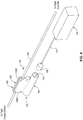
- the flight control cable sensors 150 are coupled to the second ends 147 of the flight control cables 144. Coupling the flight control cable sensors 150 to the second ends 147 promotes accuracy in detecting actuation of the flight control cables 144 because any stretch in the flight control cables 144 is less at the second ends 147 of the flight control cables 144 than at the first ends 145 of the flight control cables 144. Due to the mechanical linkage and co-movement between the flight control cables 144 and corresponding flight control surfaces, detection of actuation of the flight control cables 144 also indirectly detects actuation of the flight control surfaces. Referring to Figures 2-4 , according to some examples, each flight control cable sensor 150 includes a draw wire encoder 152, a first connector 158, and a second connector 164.
- the draw wire encoder 152 includes an extendable-retractable wire 154 that extends from and retracts into a housing 155 of the draw wire encoder 152.
- the extendable-retractable wire 154 can be made of a metallic material and have a construction that makes the extendable-retractable wire 154 tensilely non-elastic or substantially tensilely non-elastic.
- the draw wire encoder 152 further includes a spring-loaded reel 156 about which a portion of the extendable-retractable wire 154 is wound.
- a spring biases the spring-loaded reel 156 to retract the extendable-retractable wire 154 into the housing 155 and wind the extendable-retractable wire 154 onto the spring-loaded reel 156.
- the spring-loaded reel 156 rotates a first rotational direction.
- a force greater than the bias of the biasing mechanism, acts on the extendable-retractable wire 154, the extendable-retractable wire 154 is extended from the housing 155 and unwound from the spring-loaded reel 156, which causes the spring-loaded reel 156 to rotate in a second rotational direction, opposite the first rotational direction.
- rotation of the spring-loaded reel 156 is proportional to amount of extension or retraction of the extendable-retractable wire 154.
- the draw wire encoder 152 promotes a simple, fairly reliable, method of detecting the actuation of the flight control cable 144 through primarily mechanical means.
- the extendable-retractable wire 154 is prone to binding to itself on the spring-loaded reel 156, which prevents rotation of the spring-loaded reel 156 and extension and retraction of the extendable-retractable wire 154.
- the draw wire encoder 152 also includes a rotary encoder 157 coupled to the spring-loaded reel 156.
- the rotary encoder 157 is configured to detect extension and retraction of the extendable-retractable wire 154 by sensing the rotation of the spring-loaded reel 156.
- the rotary encoder 157 is also configured to output a detected actuation of the extendable-retractable wire 154, whether as raw reel rotation data or wire actuation data (converted from raw reel rotation data), to the flight controller 142.
- the first connector 158 of the flight control cable sensor 150 is co-movably fixed to an end of the extendable-retractable wire 154. Accordingly, extension of the extendable-retractable wire 154 from the housing 155 results in the first connector 158 moving away from the housing 155. In contrast, retraction of the extendable-retractable wire 154 into the housing 155 results in the first connector 158 moving toward the housing 155. In the same manner, pulling or pushing the first connector 158 causes the extendable-retractable wire 154 to extend or retract, respecti vel y.
- the second connector 164 of the flight control cable sensor 150 is co-movably fixed to the flight control cable 144. Accordingly, movement of the flight control cable 144, such as to actuate a flight control surface, causes the second connector 164 to move in the same manner, such as in the directions indicated by directional arrows 172 of Figure 2 .
- the second connector 164 is co-movably fixed to the flight control cable 144 by a clamp 162.
- the second connector 164 and the clamp 162 together form a carriage 160.
- the clamp 162 is non-movably fixedly clamped to the flight control cable 144 at the second end of the flight control cable 144.
- the clamp 162 includes a first half 166A (e.g., first clamp plate) and a second half 166B (e.g., second clamp plate) secured together by a plurality of fasteners 169.
- first half 166A and the second half 166B With the flight control cable 144 between the first half 166A and the second half 166B, the first half 166A and the second half 166B can be tightened together via the fasteners 169 to non-movably fixedly clamp the flight control cable 144 between the first half 166A and the second half 166B.
- the first half 166A and the second half 166B can include grooves for partially receiving and retaining the flight control cable 144 during and after tightening the halves together.
- the clamp 162 promotes a secure, non-movable, coupling of the second connector 164 and the flight control cable 144.
- the second connector 164 is coupled to the clamp 162. More specifically, the second connector 164 is coupled to the second half 166B of the clamp 162. In some implementations, the second connector 164 is co-formed (e.g., cast, forged, machined, etc.) with the second half 166B of the clamp 162 and forms a one-piece unitary monolithic construction with the second half 166B. Alternatively, the second connector 164 is separately formed from and attached to the second half 166B of the clamp 162.
- the first connector 158 and the second connector 164 of the flight control cable sensor 150 are configured to be removably co-movably engaged to each other up to a predetermined pull-off force.
- a pull-off force less than the predetermined pull-off force
- the first connector 158 and the second connector 164 of the flight control cable sensor 150 remain removably co-movably engaged (see, e.g., Figure 2 ).
- the first connector 158 and the second connector 164 of the flight control cable sensor 150 disengage from each other (see, e.g., Figures 3 and 4 ).
- connection between the first connector 158 and the second connector 164 can be considered a frangible connection.
- Removable co-movable engagement promotes continued proper actuation of the flight control cable 144 and corresponding flight control surface even if the extendable-retractable wire 154 binds on the spring-loaded reel 156.
- binding of the extendable-retractable wire 154 on the spring-loaded reel 156, or other malfunction of the draw wire encoder would prevent actuation or stop actuation of the flight control cable 144.
- the predetermined pull-off force is less than a force sufficient to deform (plastically or elastically) the first connector 158 and the second connector 164, except for biasing mechanisms, such as the springs of a detent mechanism, configured to deform at the predetermined pull-off force.
- the removable co-movable engagement between the first connector 158 and the second connector 164 is facilitated by the use of magnets and magnetic force.
- either of the first connector 158 and the second connector 164 includes a magnet and the other of the first connector 158 and the second connector 164 includes a ferromagnetic material attracted to the magnet.
- removable co-movable engagement between the first connector 158 and the second connector 164 includes magnetic attraction and engagement between the magnet and the ferromagnetic material.
- the predetermined pull-off force corresponds with a maximum magnetic force between the magnet and the ferromagnetic material.
- first connector 158 and the second connector 164 remain co-movably engaged until a pull-off force between the connectors exceeds the maximum magnetic force between the connectors, at which time the second connector 164 disengages (e.g., separates) from the first connector 158.
- the second connector 164 includes a receptacle 174.
- the receptacle 174 can be defined between a sidewall of the second connector 164 having an annular shape. Accordingly, the receptacle 174 can have an enclosed cross-sectional shape, which corresponds to the cross-sectional shape of the first connector 158.
- the cross-sectional shape of the receptacle 174 and the first connector 158 in the illustrated examples is round, in other examples, cross-sectional shapes other than round can be used.
- the receptacle 174 is configured to matingly or nestably receive the first connector 158.
- the receptacle 174 helps to prevent lateral movement of the first connector 158 relative to the second connector 164.
- the receptacle 174 can help to concentrate magnetic flux between the first connector 158 and the second connector 164, which improves the magnetic attraction between the first connector 158 and the second connector 164, improves magnetic efficiency, and promotes the use of smaller, less-expensive magnets.
- neither the first connector 158 nor the second connector 164 of the flight control cable sensor 150 disclosed in the present disclosure includes a receptacle, such that engagement between the first connector 158 and the second connector 164 is via only distal ends of the first connector 158 and the second connector 164.
- the second connector 164 includes a magnet 176 within the receptacle 174.
- the magnet 176 is made of a ferromagnetic material that has been permanently magnetized.
- the magnet 176 can have a cross-sectional shape that complements the cross-sectional shape of the receptacle 174. Accordingly, the magnet 176 is nestably seated within the receptacle 174 in certain implementations.
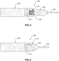
- the first connector 158 is made of a ferromagnetic material that is magnetically attracted to the magnet 176 as indicated by magnetic attraction lines 178.
- the magnetic field of the magnet 176 temporarily magnetizes the first connector 158 to magnetically retain the first connector 158 against the magnet 176 and within the receptacle 174 with a maximum magnetic force.
- the maximum magnetic force can be predetermined or preselected based on the known magnetic properties of the magnet 176 (e.g., in view of the type of ferromagnetic material, the size of the magnet, the shape of the magnet, etc.) and the known ferromagnetic properties of the first connector 158.
- the entirety of the second connector 164 is a permanent magnet, such that the magnet 176 makes up the entirety of the second connector 164.
- the first connector 158 can include a second magnet that is oriented to be magnetically attracted to the magnet 176.
- the second connector 164 including the portion of the second connector 164 defining the receptacle 174, is made of a non-ferromagnetic material in certain examples.
- at least the portion of the second connector 164 defining the receptacle 174 can be made of a second ferromagnetic material in some examples.
- the ferromagnetic properties of the material of the second connector 164 surrounding the receptacle 174 promote retention of the magnetic flux of the magnet 176 within the receptacle 174, which results in a concentration of the magnetic flux.
- the second ferromagnetic material of the second connector 164 can be the same as or different than the ferromagnetic material of the first connector 158.
- the second connector 164 includes the receptacle 174.
- the receptacle 174 does not include the magnet 176.
- the first connector 158 includes a magnet 180.
- the magnet 180 can be the same as or similar to the magnet 176, with like magnetic and geometric properties.
- the second connector 164 in this second example is made of a ferromagnetic material that is magnetically attracted to the magnet 180 as indicated by magnetic attraction lines 178.
- the magnetic field of the magnet 180 temporarily magnetizes the second connector 164 to magnetically retain the second connector 164 against the magnet 180 and correspondingly retain the first connector 158 within the receptacle 174 with a maximum magnetic force.
- portions of the second connector 164 can be made of a non-ferromagnetic material, as described above, to help concentrate magnetic flux between the first connector 158 and the second connector 164 and improve the magnetic coupling between the first connector 158 and the second connector 164
- at least the portion of the second connector 164 defining the side of the receptacle 174 can be made of a ferromagnetic material, such as the same ferromagnetic material as at the base of the receptacle 174.
- the portion of the first connector 158 to which the magnet 180 is attached can be made of a ferromagnetic material or a non-ferromagnetic material.
- the entirety of the first connector 158 is a permanent magnet, such that the magnet 180 makes up the entirety of the first connector 158.
- the second connector 164 can include a second magnet, within the receptacle 174, which is oriented to be magnetically attracted to the magnet 180.
- the first connector 148 includes a receptacle 179, instead of the second connector 164.
- the first connector 158 includes the magnet 180, which is matingly received (e.g., nestably seated) within the receptacle 179 of the first connector 148.
- the second connector 164 is matingly received within the receptacle 179 of the first connector 158.
- the magnetic field of the magnet 180 temporarily magnetizes the ferromagnetic material of the second connector 164 to magnetically retain the second connector 164 against the magnet 180 and within the receptacle 179 with a maximum magnetic force.
- at least the portion of the first connector 158 defining the receptacle 179 can be made of a ferromagnetic material.
- the entirety of the first connector 158 is a permanent magnet, such that the magnet 180 makes up the entirety of the first connector 158.
- the second connector 164 can include a magnet instead of the first connector 158 or the second connector 164 can include a second magnet, in addition to the magnet 180, that is oriented to be magnetically attracted to the magnet 180.
- the first connector 158 and the second connector 164 are removably co-movably engaged by a mechanical force instead of a magnetic force.
- the first connector 158 and the second connector 164 are removably co-movably engaged by a ball detent mechanism 181.
- the ball detent mechanism 181 includes a first portion 182 and a second portion 183.
- the first portion 182 is removably engaged with the second portion 183 and remains engaged up to a predetermined pull-off force corresponding with a mechanical biasing force of the ball detent mechanism 181. After the predetermined pull-off force is reached, the first portion 182 disengages with the second portion 183 and the first connector 158 disengages with the second connector 164.
- other types of detent mechanisms could be used instead of or in addition to a ball detent mechanism.
- the first connector 158 includes the first portion 182 and the second connector 164 includes the second portion 183.
- the first connector 158 includes the second portion 183 and the second connector 164 includes the first portion 182.
- the first portion 182 includes at least one ball 184 and a biasing mechanism 186 (e.g., spring) for each ball 184.
- the biasing mechanism 186 is configured to bias the corresponding ball 184 in a radially outward direction relative to a central axis of the first connector 158.
- Each ball 184 is retained within a corresponding first socket.
- the second portion 183 includes at least one second socket configured to receive a corresponding one of the balls 184 of the first portion 182.
- the second socket is formed in the receptacle 174 of the second connector 164.
- the second sockets of the second portion 183 are spatially aligned with the balls 184 of the first portion 182.
- the wall of the receptacle 174 forces the balls 184 radially inwardly until the balls 184 are aligned with the second sockets of the second portion 183, at which time the biasing mechanism 186 urges the balls 184 into engagement with corresponding sockets of the second portion 183.
- the balls 184 remain engages with the sockets of the second portion 183 until a pull-off force acting on the first connector 158 and the second connector 164 exceeds the combined biasing force of the biasing mechanisms 186, which equal the mechanical biasing force of the ball detent mechanism 181.
- the mechanical biasing force of the ball detent mechanism 181 can be predetermined or preselected by selecting biasing mechanisms 186 having known and desirable biasing forces.
- the second connector 164 includes the receptacle 174, in the illustrated example of Figures 11 and 12
- the first connector 158 can include the receptacle instead of the second connector 164, similar to Figures 9 and 10 .
- removably co-movably engaging the first connector 158 and the second connector 164 using magnetic force is advantageous over mechanical force or using mechanical force is advantageous over magnetic force.
- corrosion tends to negatively affect the performance of mechanical components than magnetic components. Accordingly, in environments particularly conducive to corrosion, removably co-movably engaging the first connector 158 and the second connector 164 using magnetic force may be preferable over mechanical force.
- an aircraft 200 includes structural features similar to those described above in association with the aircraft 100 of Figure 1 . Additionally, the aircraft 100 includes a system 202 for controlling flight of the aircraft 200.
- the system 202 includes a flight controller 204, a flight control cable sensor 206, a flight control surface 208, and an auxiliary actuator 210.
- the flight controller 204 controls flight characteristics of the aircraft 100 through manual and automatic techniques.
- the flight controller 204 is the same as the flight controller 142 of the aircraft 100.
- the flight controller 204 includes a flight control module 212 that is configured to automatically control at least some aspects of the flight characteristics of the aircraft 100.
- the flight control module 212 is configured to automatically control the auxiliary actuator 210, which can include a motor directly coupled to the flight control surface 208 by a mechanical coupler 246.
- the auxiliary actuator 210 further includes a position sensor, such as a rotary indicator, that detects a position of the auxiliary actuator 210 and communicates the detected position back to the flight control module 212 of the flight controller 204.
- the flight control module 212 of the flight controller 204 can determine a position of the flight control surface 208.
- Flight controller 204 Manual control of the flight characteristics of the aircraft 100 by the flight controller 204 is facilitated by mechanical coupling of the flight controller 204 to the flight control surface 208 via a flight control cable 244, which can be configured similarly to, or the same as, the flight control cable 144.
- the flight controller is operable to actuate the flight control surface 208 by actuating the flight control cable 244.
- the flight control surface 208 can be any one of various flight control surfaces of an aircraft, such as the flight control surfaces shown and described in association with the aircraft 100.
- the flight control cable sensor 206 is the same as the flight control cable sensor 150 of the aircraft 100 and is configured to detect actuation of the flight control cable 244 in the same way as the flight control cable sensor 150.
- the flight control cable sensor 206 can be coupled to a second end of the flight control cable 244, which is also coupled to the flight controller 204.
- the flight control surface 208 is coupled to a first end of the flight control cable 244, which is opposite the second end.
- the flight control cable sensor 206 in particular a draw wire encoder of the flight control cable sensor 206, is communicatively coupled with the flight controller 204 to deliver a sensed or detected position of the flight control cable 244 to the flight control module 121 of the flight controller 204.
- the flight control module 121 can determine a position of the flight control surface 208.
- the flight control module 212 of the flight controller 204 is configured to determine a status of the flight control cable sensor 206 based at least partially on the sensed position of the flight control cable 244 received from the flight control cable sensor 206.
- the status of the flight control cable sensor 206 can be one of operable (or similar indicator) or disabled (or similar indicator). As described above, when an extendable-retractable wire of the flight control cable sensor 206 gets bound, to prevent rotation of the reel of a draw wire encoder of the flight control cable sensor 206, a first connector and a second connector of the flight control cable sensor 206 disengage.
- Disengagement between the first connector and the second connector of the flight control cable sensor 206 allows the flight control cable 244 to continue to properly actuate, but results in a sensed position of the flight control cable received from the flight control cable sensor 206 to be incongruent with the position of the flight control surface.
- the flight control module 212 determines the status of the flight control cable sensor 206 is disabled. In contrast, when an incongruence is not present, the flight control module 212 determines the status of the flight control cable sensor 206 is operable.
- the flight control module 212 of the flight controller 204 detects the presence of an incongruence, and thus determines the status of the flight control cable sensor 206, by comparing the position of the flight control cable 244 received from the draw wire encoder to an indication of a position of the flight control surface 208.
- the indication of the position of the flight control surface 208 can be a mechanical indication, such as a gauge, directly coupled to the flight control cable 244. Alternatively, or additionally, the indication of the position of the flight control surface 208 can be obtained from an output of the auxiliary actuator 210.
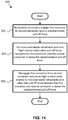
- a method 300 of detecting actuation of a flight control cable of an aircraft includes removably co-movably engaging a first connector (e.g., first connector 158), which is co-movably fixed to an extendable-retractable wire (e.g., extendable-retractable wire 154) of a draw wire encoder (e.g., draw wire encoder 152), to a second connector (e.g., second connector 164), co-movably fixed to the flight control cable, up to a predetermined pull-off force at step 302.
- a first connector e.g., first connector 158
- an extendable-retractable wire e.g., extendable-retractable wire 154
- draw wire encoder e.g., draw wire encoder 152
- second connector e.g., second connector 164
- Removably co-movably engaging the first connector to the second connector includes magnetically coupling the first connector to the second connector.
- the method 300 additionally includes co-moving the extendable-retractable wire and the flight control cable when a pull-off force between the first connector and the second connector is below the predetermined pull-off force at 304.
- the method 300 further includes disengaging the first connector from the second connector and moving the flight control cable relative to the extendable-retractable wire when the pull-off force between the first connector and the second connector is above the predetermined pull-off force at step 306. Allowing the flight control cable to move relative to the extendable-retractable wire of the draw wire encoder enables the flight control cable to continue operating properly to move the flight control surface even when the extendable-retractable wire of the draw wire encoder binds. Accordingly, in some examples, the pull-off force between the first connector and the second connector is above the predetermined pull-off force in response to the extendable-retractable wire binding to the spring-loaded reel.
- the method 300 further includes determining a first position of a flight control surface, operably coupled to the flight control cable, in response to output from the draw wire encoder, determining a second position of the flight control surface, operably coupled to the flight control cable, independently of output from the draw wire encoder, and detecting disablement of the draw wire encoder based on a difference between the first position of the flight control surface and the second position of the flight control surface being greater than a predetermined threshold.
- instances in this specification where one element is "coupled" to another element can include direct and indirect coupling.
- Direct coupling can be defined as one element coupled to and in some contact with another element.
- Indirect coupling can be defined as coupling between two elements not in direct contact with each other, but having one or more additional elements between the coupled elements.
- securing one element to another element can include direct securing and indirect securing.
- adjacent does not necessarily denote contact. For example, one element can be adjacent another element without being in contact with that element.
- the phrase "at least one of', when used with a list of items, means different combinations of one or more of the listed items may be used and only one of the items in the list may be needed.
- the item may be a particular object, thing, or category.
- "at least one of' means any combination of items or number of items may be used from the list, but not all of the items in the list may be required.
- "at least one of item A, item B, and item C" may mean item A; item A and item B; item B; item A, item B, and item C; or item B and item C.
- "at least one of item A, item B, and item C” may mean, for example, without limitation, two of item A, one of item B, and ten of item C; four of item B and seven of item C; or some other suitable combination.
- first, second, etc. are used herein merely as labels, and are not intended to impose ordinal, positional, or hierarchical requirements on the items to which these terms refer. Moreover, reference to, e.g., a “second” item does not require or preclude the existence of, e.g., a "first” or lower-numbered item, and/or, e.g., a "third" or higher-numbered item.
- a system, apparatus, structure, article, element, component, or hardware “configured to” perform a specified function is indeed capable of performing the specified function without any alteration, rather than merely having potential to perform the specified function after further modification.
- the system, apparatus, structure, article, element, component, or hardware “configured to” perform a specified function is specifically selected, created, implemented, utilized, programmed, and/or designed for the purpose of performing the specified function.
- "configured to” denotes existing characteristics of a system, apparatus, structure, article, element, component, or hardware which enable the system, apparatus, structure, article, element, component, or hardware to perform the specified function without further modification.
- a system, apparatus, structure, article, element, component, or hardware described as being “configured to” perform a particular function may additionally or alternatively be described as being “adapted to” and/or as being “operative to” perform that function.
- the schematic flow chart diagrams included herein are generally set forth as logical flow chart diagrams. As such, the depicted order and labeled steps are indicative of one example of the presented method. Other steps and methods may be conceived that are equivalent in function, logic, or effect to one or more steps, or portions thereof, of the illustrated method. Additionally, the format and symbols employed are provided to explain the logical steps of the method and are understood not to limit the scope of the method. Although various arrow types and line types may be employed in the flow chart diagrams, they are understood not to limit the scope of the corresponding method. Indeed, some arrows or other connectors may be used to indicate only the logical flow of the method. For instance, an arrow may indicate a waiting or monitoring period of unspecified duration between enumerated steps of the depicted method. Additionally, the order in which a particular method occurs may or may not strictly adhere to the order of the corresponding steps shown.
- the electronic controller and associated modules described in this specification may be implemented as a hardware circuit comprising custom VLSI circuits or gate arrays, off-the-shelf semiconductors such as logic chips, transistors, or other discrete components.
- the electronic controller may also be implemented in programmable hardware devices such as field programmable gate arrays, programmable array logic, programmable logic devices or the like.
- the electronic controller may also be implemented in code and/or software for execution by various types of processors.
- An identified module of code may, for instance, comprise one or more physical or logical blocks of executable code which may, for instance, be organized as an object, procedure, or function. Nevertheless, the executables of the electronic controller need not be physically located together, but may comprise disparate instructions stored in different locations which, when joined logically together, comprise the electronic controller and achieve the stated purpose for the electronic controller.
- code of the electronic controller may be a single instruction, or many instructions, and may even be distributed over several different code segments, among different programs, and across several memory devices.
- operational data may be identified and illustrated herein within the electronic controller, and may be embodied in any suitable form and organized within any suitable type of data structure. The operational data may be collected as a single data set, or may be distributed over different locations including over different computer readable storage devices. Where the electronic controller or portions of the electronic controller are implemented in software, the software portions are stored on one or more computer readable storage devices.
- the computer readable medium may be a computer readable storage medium.
- the computer readable storage medium may be a storage device storing the code.
- the storage device may be, for example, but not limited to, an electronic, magnetic, optical, electromagnetic, infrared, holographic, micromechanical, or semiconductor system, apparatus, or device, or any suitable combination of the foregoing.
- a storage device More specific examples (a non-exhaustive list) of the storage device would include the following: an electrical connection having one or more wires, a portable computer diskette, a hard disk, a random access memory (RAM), a read-only memory (ROM), an erasable programmable read-only memory (EPROM or Flash memory), a portable compact disc read-only memory (CD-ROM), an optical storage device, a magnetic storage device, or any suitable combination of the foregoing.
- a computer readable storage medium may be any tangible medium that can contain, or store a program for use by or in connection with an instruction execution system, apparatus, or device.
- Code for carrying out operations for examples may be written in any combination of one or more programming languages including an object oriented programming language such as Python, Ruby, Java, Smalltalk, C++, or the like, and conventional procedural programming languages, such as the "C" programming language, or the like, and/or machine languages such as assembly languages.
- the code may execute entirely on the user's computer, partly on the user's computer, as a stand-alone software package, partly on the user's computer and partly on a remote computer or entirely on the remote computer or server.
- the remote computer may be connected to the user's computer through any type of network, including a local area network (LAN) or a wide area network (WAN), or the connection may be made to an external computer (for example, through the Internet using an Internet Service Provider).
- LAN local area network
- WAN wide area network
- Internet Service Provider for example, AT&T, Verizon, Comcast, etc.
- the code may also be stored in a storage device that can direct a computer, other programmable data processing apparatus, or other devices to function in a particular manner, such that the instructions stored in the storage device produce an article of manufacture including instructions which implement the function/act specified in the schematic flowchart diagrams and/or schematic block diagrams block or blocks.
- the code may also be loaded onto a computer, other programmable data processing apparatus, or other devices to cause a series of operational steps to be performed on the computer, other programmable apparatus or other devices to produce a computer implemented process such that the code which execute on the computer or other programmable apparatus provide processes for implementing the functions/acts specified in the flowchart and/or block diagram block or blocks.
- each block in the schematic flowchart diagrams and/or schematic block diagrams may represent a module, segment, or portion of code, which comprises one or more executable instructions of the code for implementing the specified logical function(s).
Landscapes
- Engineering & Computer Science (AREA)
- Physics & Mathematics (AREA)
- General Physics & Mathematics (AREA)
- Aviation & Aerospace Engineering (AREA)
- Mechanical Engineering (AREA)
- Manufacturing & Machinery (AREA)
- Transportation (AREA)
- Automation & Control Theory (AREA)
- Details Of Connecting Devices For Male And Female Coupling (AREA)
Abstract
Description
- This disclosure relates generally to aircraft, and more particularly to a flight control cable sensor for detecting actuation of a flight control cable of an aircraft.
- Flight control cables are used to mechanically actuate flight control surfaces of aircraft. Sensors are used to detect actuation of flight control cables. Sensed conditions from the sensors can be used to determine the position of the flight control surfaces. Some sensors for detecting actuation of flight control cables can negatively affect operation of the flight control cables if the sensors become disabled.
- The subject matter of the present application has been developed in response to the present state of the art, and in particular, in response to the shortcomings of conventional sensors for sensing flight control cables that have not yet been fully solved by currently available techniques. Accordingly, the subject matter of the present application has been developed to provide a flight control cable sensor, and associated systems and methods, that overcome at least some of the above-discussed shortcomings of prior art flight control cable sensors.
- Disclosed herein is a flight control cable sensor for detecting actuation of a flight control cable of an aircraft. The flight control cable sensor comprises a draw wire encoder, comprising an extendable-retractable wire. The flight control cable sensor further comprises a first connector, co-movably fixed to the extendable-retractable wire, and a second connector, co-movably fixable to the flight control cable and configured to removably co-movably engage the first connector up to a predetermined pull-off force. The preceding subject matter of this paragraph characterizes example 1 of the present disclosure.
- One of the first connector or the second connector comprises a magnet. An other of the first connector or the second connector is made of a ferromagnetic material magnetically attracted to the magnet. Removable co-movable engagement between the first connector and the second connector comprises magnetic engagement between the magnet and the ferromagnetic material. The predetermined pull-off force corresponds with a maximum magnetic force between the magnet and the ferromagnetic material. The preceding subject matter of this paragraph characterizes example 2 of the present disclosure, wherein example 2 also includes the subject matter according to example 1, above.
- The second connector comprises a receptacle. The first connector is matingly receivable within the receptacle to removably co-movably engage the first connector and the second connector. The preceding subject matter of this paragraph characterizes example 3 of the present disclosure, wherein example 3 also includes the subject matter according to example 2, above.
- The magnet is within the receptacle of the second connector. The first connector is made of the ferromagnetic material magnetically attracted to the magnet. The preceding subject matter of this paragraph characterizes example 4 of the present disclosure, wherein example 4 also includes the subject matter according to example 3, above.
- A portion of the second connector defining the receptacle is made of a second ferromagnetic material. The preceding subject matter of this paragraph characterizes example 5 of the present disclosure, wherein example 5 also includes the subject matter according to example 4, above.
- The first connector comprises the magnet. The second connector is made of the ferromagnetic material magnetically attracted to the magnet. The preceding subject matter of this paragraph characterizes example 6 of the present disclosure, wherein example 6 also includes the subject matter according to example 3, above.
- The first connector comprises a receptacle. The second connector is matingly receivable within the receptacle to removably co-movably engage the first connector and the second connector. The preceding subject matter of this paragraph characterizes example 7 of the present disclosure, wherein example 7 also includes the subject matter according to example 2, above.
- The first connector comprises a first portion of a ball detent mechanism. The second connector comprises a second portion of the ball detent mechanism. Removable co-movable engagement between the first connector and the second connector comprises engagement between the first portion of the ball detent mechanism and the second portion of the ball detent mechanism. The predetermined pull-off force corresponds with a mechanical biasing force of the ball detent mechanism. The preceding subject matter of this paragraph characterizes example 8 of the present disclosure, wherein example 8 also includes the subject matter according to example 1, above.
- The flight control sensor further comprises a carriage comprising a clamp, configured to non-movably fixedly clamp to the flight control cable, and the second connector. The second connector is coupled to the clamp. The preceding subject matter of this paragraph characterizes example 9 of the present disclosure, wherein example 9 also includes the subject matter according to any one of examples 1-8, above.
- The draw wire encoder further comprises a spring-loaded reel about which a portion of the extendable-retractable wire is wound. The draw wire encoder also comprises a rotary encoder coupled to the spring-loaded reel and configured to detect extension and retraction of the extendable-retractable wire. The preceding subject matter of this paragraph characterizes example 10 of the present disclosure, wherein example 10 also includes the subject matter according to any one of examples 1-9, above.
- Also disclosed herein is an aircraft. The aircraft comprises a flight control cable comprising a first end and a second end opposite the first end. The aircraft additional comprises a flight control surface coupled to the first end of the flight control cable and a flight controller coupled to the second end of the flight control cable. The flight controller is operable to actuate the flight control surface by actuating the flight control cable. The aircraft further comprises a flight control cable sensor that comprises a draw wire encoder comprising an extendable-retractable wire, a first connector co-movably fixed to the extendable-retractable wire, and a second connector co-movably fixed to the flight control cable and removably co-movably engaged with the first connector up to a predetermined pull-off force. The draw wire encoder is communicatively coupled with the flight controller to deliver a sensed position of the flight control cable to the flight controller. The flight controller is configured to determine a status of the flight control cable sensor based at least partially on the sensed position of the flight control cable received from the draw wire encoder. The preceding subject matter of this paragraph characterizes example 11 of the present disclosure.
- The flight controller determines the status of the flight control cable sensor by comparing the sensed position of the flight control cable received from the draw wire encoder to an indication of a position of the flight control surface. The preceding subject matter of this paragraph characterizes example 12 of the present disclosure, wherein example 12 also includes the subject matter according to example 11, above.
- The aircraft further comprises an auxiliary actuator coupled to the flight control surface and operable to actuate the flight control surface. The secondary indication of the position of the flight control surface comprises an output from the auxiliary actuator. The preceding subject matter of this paragraph characterizes example 13 of the present disclosure, wherein example 13 also includes the subject matter according to example 12, above.
- The first connector comprises a first magnetic material. The second connector comprises a second magnetic material, magnetically attracted to the first magnetic material. Removable co-movable engagement between the first connector and the second connector comprises magnetic engagement between the first magnetic material and the second magnetic material. The predetermined pull-off force corresponds with a magnetic force between the first magnetic material and the second magnetic material. The preceding subject matter of this paragraph characterizes example 14 of the present disclosure, wherein example 14 also includes the subject matter according to any one of examples 11-13, above.
- One of the first connector or the second connector comprises a receptacle. An other one of the first connector or the second connector is matingly received within the receptacle. An entirety of the receptacle is made of one of the first magnetic material or the second magnetic material. The preceding subject matter of this paragraph characterizes example 15 of the present disclosure, wherein example 15 also includes the subject matter according to example 14, above.
- The second connector is co-movably fixed to the second end of the flight control cable. The preceding subject matter of this paragraph characterizes example 16 of the present disclosure, wherein example 16 also includes the subject matter according to any one of examples 11-15, above.
- Additionally disclosed herein is a method of detecting actuation of a flight control cable of an aircraft. The method includes removably co-movably engaging a first connector, co-movably fixed to an extendable-retractable wire of a draw wire encoder, to a second connector, co-movably fixed to the flight control cable, up to a predetermined pull-off force. The method also includes co-moving the extendable-retractable wire and the flight control cable when a pull-off force between the first connector and the second connector is below the predetermined pull-off force. The method further includes disengaging the first connector from the second connector and moving the flight control cable relative to the extendable-retractable wire when the pull-off force between the first connector and the second connector is above the predetermined pull-off force. The preceding subject matter of this paragraph characterizes example 17 of the present disclosure.
- The draw wire encoder further comprises a spring-loaded reel about which a portion of the extendable-retractable wire is wound. The draw wire encoder additionally comprises a rotary encoder coupled to the spring-loaded reel and configured to detect extension and retraction of the extendable-retractable wire. The pull-off force between the first connector and the second connector is above the predetermined pull-off force in response to the extendable-retractable wire binding to the spring-loaded reel. The preceding subject matter of this paragraph characterizes example 18 of the present disclosure, wherein example 18 also includes the subject matter according to example 17, above.
- The method also comprises determining a first position of a flight control surface, operably coupled to the flight control cable, in response to output from the draw wire encoder, determining a second position of the flight control surface, operably coupled to the flight control cable, independently of output from the draw wire encoder, and detecting disablement of the draw wire encoder based on a difference between the first position of the flight control surface and the second position of the flight control surface being greater than a predetermined threshold. The preceding subject matter of this paragraph characterizes example 19 of the present disclosure, wherein example 19 also includes the subject matter according to example 18, above.
- Removably co-movably engaging the first connector to the second connector comprises magnetically coupling the first connector to the second connector. The preceding subject matter of this paragraph characterizes example 20 of the present disclosure, wherein example 20 also includes the subject matter according to any one of examples 17-19, above.
- The described features, structures, advantages, and/or characteristics of the subject matter of the present disclosure may be combined in any suitable manner in one or more examples and/or implementations. In the following description, numerous specific details are provided to impart a thorough understanding of examples of the subject matter of the present disclosure. One skilled in the relevant art will recognize that the subject matter of the present disclosure may be practiced without one or more of the specific features, details, components, materials, and/or methods of a particular example or implementation. In other instances, additional features and advantages may be recognized in certain examples and/or implementations that may not be present in all examples or implementations. Further, in some instances, well-known structures, materials, or operations are not shown or described in detail to avoid obscuring details of the subject matter of the present disclosure. The features and advantages of the subject matter of the present disclosure will become more fully apparent from the following description and appended claims, or may be learned by the practice of the subject matter as set forth hereinafter.
- In order that the advantages of the subject matter may be more readily understood, a more particular description of the subject matter briefly described above will be rendered by reference to specific examples that are illustrated in the appended drawings. Understanding that these drawings depict only typical examples of the subject matter and are not therefore to be considered to be limiting of its scope, the subject matter will be described and explained with additional specificity and detail through the use of the drawings, in which:
-
Figure 1 is a top plan view of an aircraft, according to one or more examples of the present disclosure; -
Figure 2 is a perspective view of a flight control cable sensor, according to one or more examples of the present disclosure; -
Figure 3 is a perspective view of the flight control cable sensor ofFigure 2 , shown with a first connector disengaged from a second connector, according to one or more examples of the present disclosure; -
Figure 4 is a perspective view of a flight control cable sensor, according to one or more examples of the present disclosure; -
Figure 5 is a cross-sectional side elevation view of the first connector and the second connector of the flight control cable sensor ofFigure 2 , taken along the line 5-5 ofFigure 2 , according to one or more examples of the present disclosure; -
Figure 6 is a cross-sectional side elevation view of the first connector and the second connector of the flight control cable sensor ofFigure 3 , taken along the line 6-6 ofFigure 3 , according to one or more examples of the present disclosure; -
Figure 7 is a cross-sectional side elevation view of the first connector and the second connector of a flight control cable sensor, taken along a line similar to the line 5-5 ofFigure 2 , according to one or more examples of the present disclosure; -
Figure 8 is a cross-sectional side elevation view of the first connector and the second connector of a flight control cable sensor, taken along a line similar to the line 6-6 ofFigure 3 , according to one or more examples of the present disclosure; -
Figure 9 is a cross-sectional side elevation view of the first connector and the second connector of a flight control cable sensor, taken along a line similar to the line 5-5 ofFigure 2 , according to one or more examples of the present disclosure; -
Figure 10 is a cross-sectional side elevation view of the first connector and the second connector of a flight control cable sensor, taken along a line similar to the line 6-6 ofFigure 3 , according to one or more examples of the present disclosure; -
Figure 11 is a cross-sectional side elevation view of the first connector and the second connector of a flight control cable sensor, taken along a line similar to the line 5-5 ofFigure 2 , according to one or more examples of the present disclosure; -
Figure 12 is a cross-sectional side elevation view of the first connector and the second connector of a flight control cable sensor, taken along a line similar to the line 6-6 ofFigure 3 , according to one or more examples of the present disclosure; -
Figure 13 is a schematic box diagram of an aircraft, according to one or more examples of the present disclosure; and -
Figure 14 is schematic flow chart of a method of detecting actuation of a flight control cable of an aircraft, according to one or more examples of the present disclosure. - Reference throughout this specification to "one example," "an example," or similar language means that a particular feature, structure, or characteristic described in connection with the example is included in at least one example of the present disclosure. Appearances of the phrases "in one example," "in an example," and similar language throughout this specification may, but do not necessarily, all refer to the same example. Similarly, the use of the term "implementation" means an implementation having a particular feature, structure, or characteristic described in connection with one or more examples of the present disclosure, however, absent an express correlation to indicate otherwise, an implementation may be associated with one or more examples.
- Referring to
Figure 1 , one example of anaircraft 100 is shown. Theaircraft 100 can be any of various types of aircraft, such as commercial aircraft used for the transportation of passengers, military aircraft for military operations, personal aircraft, and the like. As depicted, theaircraft 100 represents a passenger airplane. The depictedaircraft 100 includes a body 112 (e.g., fuselage), a pair ofwings 114 coupled to and extending from thebody 112, avertical stabilizer 116 coupled to thebody 112, and a pair ofhorizontal stabilizers 118 coupled to thebody 112 and/or thevertical stabilizer 116. - The
aircraft 100 further includes a plurality of flight control surfaces, otherwise known as adjustable aerodynamic surfaces, which are adjustable to change the flight of theaircraft 100 by changing the characteristics of air flow over, around, and trailing the surfaces. For example, eachwing 114, has coupled thereto, anaileron 124, flaps 126, spoilers (not shown), and slats 130. Additionally, thevertical stabilizer 116 includes a rudder (not shown), and eachhorizontal stabilizer 118 includes anelevator 120. For responsive control of the flight of theaircraft 100, the relative position of the flight control surfaces of the aircraft, such as those shown inFigure 1 , should be capable of precise adjustment. - The flight control surfaces are adjustable by mechanically actuating (e.g., pushing/pulling) flight control cables coupled to the flight control surfaces. For example, in the
aircraft 100 ofFigure 1 , each of theailerons 124 andelevators 120 is operably coupled to a respective one of a plurality offlight control cables 144. Although not shown, other flight control surfaces of theaircraft 100 are also operably coupled to respective flight control cables. - Each
flight control cable 144 has afirst end 145 and asecond end 147 that is opposite thefirst end 145. Thefirst end 145 of eachflight control cable 144 is directly coupled to a corresponding one of the flight control surfaces. The first ends 145 of theflight control cables 144 are coupled to respective flight control surfaces using a coupling technique that facilitates actuation of the flight control surfaces when theflight control cables 144 are pushed (e.g., extended) or pulled (e.g., retracted), such as in the directions indicated bydirectional arrows 170 ofFigure 2 . The second ends 147 of theflight control cables 144 are directly coupled to aflight controller 142 of theaircraft 100. The second ends 147 are coupled to theflight controller 142 using a coupling technique that facilitates independent pushing or pulling of theflight control cables 144. Theflight control cables 144 are made of a metallic material in some examples and are tensilely non-elastic or substantially tensilely non-elastic. - The
flight controller 142 includes manual controls, in some examples, which are directly mechanically linked to theflight control cables 144. Manual controls include a pilot-operated control stick, among other manual control devices. Additionally, theflight controller 142 can include software-driven automatic controls, such as autopilot capability, which are electronically linked to theflight control cables 144 via auxiliary actuators, such as servo motors and the like. It is recognized that electronically-controlled actuation of the flight control surfaces via auxiliary actuators also causes a corresponding actuation of theflight control cables 144 because of the mechanical linkage between theflight control cables 144 and the flight control surfaces. To help route theflight control cables 144 from theflight controller 142 to the corresponding flight control surfaces, theaircraft 100 may include one ormore pulleys 146 or other cable-routing mechanisms. - The
aircraft 100 further includes a plurality of flightcontrol cable sensors 150 each configured to detect (e.g., monitor) actuation of a correspondingflight control cable 144. In some examples, the flightcontrol cable sensors 150 are coupled to the second ends 147 of theflight control cables 144. Coupling the flightcontrol cable sensors 150 to the second ends 147 promotes accuracy in detecting actuation of theflight control cables 144 because any stretch in theflight control cables 144 is less at the second ends 147 of theflight control cables 144 than at the first ends 145 of theflight control cables 144. Due to the mechanical linkage and co-movement between theflight control cables 144 and corresponding flight control surfaces, detection of actuation of theflight control cables 144 also indirectly detects actuation of the flight control surfaces. Referring toFigures 2-4 , according to some examples, each flightcontrol cable sensor 150 includes adraw wire encoder 152, afirst connector 158, and asecond connector 164. - The
draw wire encoder 152 includes an extendable-retractable wire 154 that extends from and retracts into ahousing 155 of thedraw wire encoder 152. The extendable-retractable wire 154 can be made of a metallic material and have a construction that makes the extendable-retractable wire 154 tensilely non-elastic or substantially tensilely non-elastic. Thedraw wire encoder 152 further includes a spring-loadedreel 156 about which a portion of the extendable-retractable wire 154 is wound. Although not shown, a spring, or other biasing mechanism, biases the spring-loadedreel 156 to retract the extendable-retractable wire 154 into thehousing 155 and wind the extendable-retractable wire 154 onto the spring-loadedreel 156. As the extendable-retractable wire 154 is wound onto the spring-loadedreel 156, the spring-loadedreel 156 rotates a first rotational direction. In contrast, when a force, greater than the bias of the biasing mechanism, acts on the extendable-retractable wire 154, the extendable-retractable wire 154 is extended from thehousing 155 and unwound from the spring-loadedreel 156, which causes the spring-loadedreel 156 to rotate in a second rotational direction, opposite the first rotational direction. In this manner, rotation of the spring-loadedreel 156 is proportional to amount of extension or retraction of the extendable-retractable wire 154. Thedraw wire encoder 152 promotes a simple, fairly reliable, method of detecting the actuation of theflight control cable 144 through primarily mechanical means. However, under some circumstances, the extendable-retractable wire 154 is prone to binding to itself on the spring-loadedreel 156, which prevents rotation of the spring-loadedreel 156 and extension and retraction of the extendable-retractable wire 154. - The
draw wire encoder 152 also includes arotary encoder 157 coupled to the spring-loadedreel 156. Therotary encoder 157 is configured to detect extension and retraction of the extendable-retractable wire 154 by sensing the rotation of the spring-loadedreel 156. Therotary encoder 157 is also configured to output a detected actuation of the extendable-retractable wire 154, whether as raw reel rotation data or wire actuation data (converted from raw reel rotation data), to theflight controller 142. - The
first connector 158 of the flightcontrol cable sensor 150 is co-movably fixed to an end of the extendable-retractable wire 154. Accordingly, extension of the extendable-retractable wire 154 from thehousing 155 results in thefirst connector 158 moving away from thehousing 155. In contrast, retraction of the extendable-retractable wire 154 into thehousing 155 results in thefirst connector 158 moving toward thehousing 155. In the same manner, pulling or pushing thefirst connector 158 causes the extendable-retractable wire 154 to extend or retract, respecti vel y. - The
second connector 164 of the flightcontrol cable sensor 150 is co-movably fixed to theflight control cable 144. Accordingly, movement of theflight control cable 144, such as to actuate a flight control surface, causes thesecond connector 164 to move in the same manner, such as in the directions indicated bydirectional arrows 172 ofFigure 2 . In some examples, thesecond connector 164 is co-movably fixed to theflight control cable 144 by aclamp 162. Thesecond connector 164 and theclamp 162 together form acarriage 160. Theclamp 162 is non-movably fixedly clamped to theflight control cable 144 at the second end of theflight control cable 144. According to some implementations, theclamp 162 includes afirst half 166A (e.g., first clamp plate) and asecond half 166B (e.g., second clamp plate) secured together by a plurality offasteners 169. With theflight control cable 144 between thefirst half 166A and thesecond half 166B, thefirst half 166A and thesecond half 166B can be tightened together via thefasteners 169 to non-movably fixedly clamp theflight control cable 144 between thefirst half 166A and thesecond half 166B. Thefirst half 166A and thesecond half 166B can include grooves for partially receiving and retaining theflight control cable 144 during and after tightening the halves together. Theclamp 162 promotes a secure, non-movable, coupling of thesecond connector 164 and theflight control cable 144. - The
second connector 164 is coupled to theclamp 162. More specifically, thesecond connector 164 is coupled to thesecond half 166B of theclamp 162. In some implementations, thesecond connector 164 is co-formed (e.g., cast, forged, machined, etc.) with thesecond half 166B of theclamp 162 and forms a one-piece unitary monolithic construction with thesecond half 166B. Alternatively, thesecond connector 164 is separately formed from and attached to thesecond half 166B of theclamp 162. - The
first connector 158 and thesecond connector 164 of the flightcontrol cable sensor 150 are configured to be removably co-movably engaged to each other up to a predetermined pull-off force. In other words, when acted upon by a pull-off force less than the predetermined pull-off force, thefirst connector 158 and thesecond connector 164 of the flightcontrol cable sensor 150 remain removably co-movably engaged (see, e.g.,Figure 2 ). However, when acted upon by a pull-off force more than the predetermined pull-off force, thefirst connector 158 and thesecond connector 164 of the flightcontrol cable sensor 150 disengage from each other (see, e.g.,Figures 3 and4 ). In this manner, the connection between thefirst connector 158 and thesecond connector 164 can be considered a frangible connection. Removable co-movable engagement promotes continued proper actuation of theflight control cable 144 and corresponding flight control surface even if the extendable-retractable wire 154 binds on the spring-loadedreel 156. Without removable co-movable engagement between thefirst connector 158 and thesecond connector 164, binding of the extendable-retractable wire 154 on the spring-loadedreel 156, or other malfunction of the draw wire encoder, would prevent actuation or stop actuation of theflight control cable 144. According to certain examples, the predetermined pull-off force is less than a force sufficient to deform (plastically or elastically) thefirst connector 158 and thesecond connector 164, except for biasing mechanisms, such as the springs of a detent mechanism, configured to deform at the predetermined pull-off force. - In some examples illustrated in
Figures 2-11 , the removable co-movable engagement between thefirst connector 158 and thesecond connector 164 is facilitated by the use of magnets and magnetic force. Generally, either of thefirst connector 158 and thesecond connector 164 includes a magnet and the other of thefirst connector 158 and thesecond connector 164 includes a ferromagnetic material attracted to the magnet. Accordingly, removable co-movable engagement between thefirst connector 158 and thesecond connector 164 includes magnetic attraction and engagement between the magnet and the ferromagnetic material. The predetermined pull-off force corresponds with a maximum magnetic force between the magnet and the ferromagnetic material. Accordingly, thefirst connector 158 and thesecond connector 164 remain co-movably engaged until a pull-off force between the connectors exceeds the maximum magnetic force between the connectors, at which time thesecond connector 164 disengages (e.g., separates) from thefirst connector 158. - Referring to
Figures 4-8 , in some examples, thesecond connector 164 includes areceptacle 174. Thereceptacle 174 can be defined between a sidewall of thesecond connector 164 having an annular shape. Accordingly, thereceptacle 174 can have an enclosed cross-sectional shape, which corresponds to the cross-sectional shape of thefirst connector 158. Although the cross-sectional shape of thereceptacle 174 and thefirst connector 158 in the illustrated examples is round, in other examples, cross-sectional shapes other than round can be used. Thereceptacle 174 is configured to matingly or nestably receive thefirst connector 158. Thereceptacle 174 helps to prevent lateral movement of thefirst connector 158 relative to thesecond connector 164. Moreover, as explained in more detail below, thereceptacle 174 can help to concentrate magnetic flux between thefirst connector 158 and thesecond connector 164, which improves the magnetic attraction between thefirst connector 158 and thesecond connector 164, improves magnetic efficiency, and promotes the use of smaller, less-expensive magnets. However, in some examples, neither thefirst connector 158 nor thesecond connector 164 of the flightcontrol cable sensor 150 disclosed in the present disclosure includes a receptacle, such that engagement between thefirst connector 158 and thesecond connector 164 is via only distal ends of thefirst connector 158 and thesecond connector 164. - In a first example shown in
Figures 5 and 6 , thesecond connector 164 includes amagnet 176 within thereceptacle 174. Themagnet 176 is made of a ferromagnetic material that has been permanently magnetized. Themagnet 176 can have a cross-sectional shape that complements the cross-sectional shape of thereceptacle 174. Accordingly, themagnet 176 is nestably seated within thereceptacle 174 in certain implementations. Thefirst connector 158 is made of a ferromagnetic material that is magnetically attracted to themagnet 176 as indicated by magnetic attraction lines 178. When thefirst connector 158 is matingly received within thereceptacle 174 of thesecond connector 164, the magnetic field of themagnet 176 temporarily magnetizes thefirst connector 158 to magnetically retain thefirst connector 158 against themagnet 176 and within thereceptacle 174 with a maximum magnetic force. The maximum magnetic force can be predetermined or preselected based on the known magnetic properties of the magnet 176 (e.g., in view of the type of ferromagnetic material, the size of the magnet, the shape of the magnet, etc.) and the known ferromagnetic properties of thefirst connector 158. Although not shown, in some implementations, the entirety of thesecond connector 164 is a permanent magnet, such that themagnet 176 makes up the entirety of thesecond connector 164. Additionally, although not shown, in certain implementations, thefirst connector 158 can include a second magnet that is oriented to be magnetically attracted to themagnet 176. - The
second connector 164, including the portion of thesecond connector 164 defining thereceptacle 174, is made of a non-ferromagnetic material in certain examples. However, to help concentrate magnetic flux between thefirst connector 158 and thesecond connector 164 and improve the magnetic coupling between thefirst connector 158 and thesecond connector 164, at least the portion of thesecond connector 164 defining thereceptacle 174 can be made of a second ferromagnetic material in some examples. The ferromagnetic properties of the material of thesecond connector 164 surrounding thereceptacle 174 promote retention of the magnetic flux of themagnet 176 within thereceptacle 174, which results in a concentration of the magnetic flux. The second ferromagnetic material of thesecond connector 164 can be the same as or different than the ferromagnetic material of thefirst connector 158. - Referring to
Figures 7 and 8 , a second example of thefirst connector 158 and thesecond connector 164 is shown. Similar to the first example ofFigures 5 and 6 , thesecond connector 164 includes thereceptacle 174. However, unlike the first example ofFigures 5 and 6 , thereceptacle 174 does not include themagnet 176. Rather, in the second example ofFigures 7 and 8 , thefirst connector 158 includes amagnet 180. Themagnet 180 can be the same as or similar to themagnet 176, with like magnetic and geometric properties. - The
second connector 164 in this second example, at least at the base of thereceptacle 174, is made of a ferromagnetic material that is magnetically attracted to themagnet 180 as indicated by magnetic attraction lines 178. When thefirst connector 158 is matingly received within thereceptacle 174 of thesecond connector 164, the magnetic field of themagnet 180 temporarily magnetizes thesecond connector 164 to magnetically retain thesecond connector 164 against themagnet 180 and correspondingly retain thefirst connector 158 within thereceptacle 174 with a maximum magnetic force. Although portions of thesecond connector 164, other than at the base of thereceptacle 174, can be made of a non-ferromagnetic material, as described above, to help concentrate magnetic flux between thefirst connector 158 and thesecond connector 164 and improve the magnetic coupling between thefirst connector 158 and thesecond connector 164, at least the portion of thesecond connector 164 defining the side of thereceptacle 174 can be made of a ferromagnetic material, such as the same ferromagnetic material as at the base of thereceptacle 174. In this second example, the portion of thefirst connector 158 to which themagnet 180 is attached can be made of a ferromagnetic material or a non-ferromagnetic material. Making the portion of thefirst connector 158 to which themagnet 180 is attached out of a ferromagnetic material can improve the magnetic coupling between thefirst connector 158 and thesecond connector 164. Although not shown, in some implementations, the entirety of thefirst connector 158 is a permanent magnet, such that themagnet 180 makes up the entirety of thefirst connector 158. Additionally, although not shown, in certain implementations, thesecond connector 164 can include a second magnet, within thereceptacle 174, which is oriented to be magnetically attracted to themagnet 180. - Referring to
Figures 9 and 10 , a third example of thefirst connector 158 and thesecond connector 164 is shown. In contrast to the first example ofFigures 5 and 6 and the second examples ofFigures 7 and 8 , the first connector 148 includes areceptacle 179, instead of thesecond connector 164. In the illustrated implementation, thefirst connector 158 includes themagnet 180, which is matingly received (e.g., nestably seated) within thereceptacle 179 of the first connector 148. Thesecond connector 164 is matingly received within thereceptacle 179 of thefirst connector 158. When thesecond connector 164 is matingly received within thereceptacle 179 of thefirst connector 158, the magnetic field of themagnet 180 temporarily magnetizes the ferromagnetic material of thesecond connector 164 to magnetically retain thesecond connector 164 against themagnet 180 and within thereceptacle 179 with a maximum magnetic force. To help concentrate magnetic flux between thefirst connector 158 and thesecond connector 164 and improve the magnetic coupling between thefirst connector 158 and thesecond connector 164, at least the portion of thefirst connector 158 defining thereceptacle 179 can be made of a ferromagnetic material. Although not shown, in some implementations, the entirety of thefirst connector 158 is a permanent magnet, such that themagnet 180 makes up the entirety of thefirst connector 158. Additionally, although not shown, in certain implementations, thesecond connector 164 can include a magnet instead of thefirst connector 158 or thesecond connector 164 can include a second magnet, in addition to themagnet 180, that is oriented to be magnetically attracted to themagnet 180. - In some examples, the
first connector 158 and thesecond connector 164 are removably co-movably engaged by a mechanical force instead of a magnetic force. For example, referring toFigures 11 and 12 , thefirst connector 158 and thesecond connector 164 are removably co-movably engaged by a ball detent mechanism 181. The ball detent mechanism 181 includes afirst portion 182 and asecond portion 183. Thefirst portion 182 is removably engaged with thesecond portion 183 and remains engaged up to a predetermined pull-off force corresponding with a mechanical biasing force of the ball detent mechanism 181. After the predetermined pull-off force is reached, thefirst portion 182 disengages with thesecond portion 183 and thefirst connector 158 disengages with thesecond connector 164. It is recognized that other types of detent mechanisms could be used instead of or in addition to a ball detent mechanism. - In the illustrated example, the
first connector 158 includes thefirst portion 182 and thesecond connector 164 includes thesecond portion 183. However, in other examples, thefirst connector 158 includes thesecond portion 183 and thesecond connector 164 includes thefirst portion 182. Thefirst portion 182 includes at least oneball 184 and a biasing mechanism 186 (e.g., spring) for eachball 184. Thebiasing mechanism 186 is configured to bias thecorresponding ball 184 in a radially outward direction relative to a central axis of thefirst connector 158. Eachball 184 is retained within a corresponding first socket. Thesecond portion 183 includes at least one second socket configured to receive a corresponding one of theballs 184 of thefirst portion 182. In the illustrated example, the second socket is formed in thereceptacle 174 of thesecond connector 164. The second sockets of thesecond portion 183 are spatially aligned with theballs 184 of thefirst portion 182. - In the case of the illustrated example, as the
first connector 158 is inserted into thereceptacle 174 of thesecond connector 164, the wall of thereceptacle 174 forces theballs 184 radially inwardly until theballs 184 are aligned with the second sockets of thesecond portion 183, at which time thebiasing mechanism 186 urges theballs 184 into engagement with corresponding sockets of thesecond portion 183. Theballs 184 remain engages with the sockets of thesecond portion 183 until a pull-off force acting on thefirst connector 158 and thesecond connector 164 exceeds the combined biasing force of the biasingmechanisms 186, which equal the mechanical biasing force of the ball detent mechanism 181. The mechanical biasing force of the ball detent mechanism 181 can be predetermined or preselected by selecting biasingmechanisms 186 having known and desirable biasing forces. Although thesecond connector 164 includes thereceptacle 174, in the illustrated example ofFigures 11 and 12 , in other examples, thefirst connector 158 can include the receptacle instead of thesecond connector 164, similar toFigures 9 and 10 . - It is recognized that in certain environments or under operating conditions, removably co-movably engaging the
first connector 158 and thesecond connector 164 using magnetic force is advantageous over mechanical force or using mechanical force is advantageous over magnetic force. For example, corrosion tends to negatively affect the performance of mechanical components than magnetic components. Accordingly, in environments particularly conducive to corrosion, removably co-movably engaging thefirst connector 158 and thesecond connector 164 using magnetic force may be preferable over mechanical force. - Referring to
Figure 13 , anaircraft 200 according to one example is shown. Theaircraft 200 includes structural features similar to those described above in association with theaircraft 100 ofFigure 1 . Additionally, theaircraft 100 includes asystem 202 for controlling flight of theaircraft 200. Thesystem 202 includes aflight controller 204, a flightcontrol cable sensor 206, aflight control surface 208, and anauxiliary actuator 210. - The
flight controller 204 controls flight characteristics of theaircraft 100 through manual and automatic techniques. In some examples, theflight controller 204 is the same as theflight controller 142 of theaircraft 100. Theflight controller 204 includes aflight control module 212 that is configured to automatically control at least some aspects of the flight characteristics of theaircraft 100. For example, theflight control module 212 is configured to automatically control theauxiliary actuator 210, which can include a motor directly coupled to theflight control surface 208 by amechanical coupler 246. Theauxiliary actuator 210 further includes a position sensor, such as a rotary indicator, that detects a position of theauxiliary actuator 210 and communicates the detected position back to theflight control module 212 of theflight controller 204. In response to the detected position from theauxiliary actuator 210, theflight control module 212 of theflight controller 204 can determine a position of theflight control surface 208. - Manual control of the flight characteristics of the
aircraft 100 by theflight controller 204 is facilitated by mechanical coupling of theflight controller 204 to theflight control surface 208 via aflight control cable 244, which can be configured similarly to, or the same as, theflight control cable 144. In other words, the flight controller is operable to actuate theflight control surface 208 by actuating theflight control cable 244. Theflight control surface 208 can be any one of various flight control surfaces of an aircraft, such as the flight control surfaces shown and described in association with theaircraft 100. - Coupled to the flight control cable at a location between the
flight controller 204 and theflight control surface 208 is the flightcontrol cable sensor 206. The flightcontrol cable sensor 206 is the same as the flightcontrol cable sensor 150 of theaircraft 100 and is configured to detect actuation of theflight control cable 244 in the same way as the flightcontrol cable sensor 150. The flightcontrol cable sensor 206 can be coupled to a second end of theflight control cable 244, which is also coupled to theflight controller 204. In contrast, theflight control surface 208 is coupled to a first end of theflight control cable 244, which is opposite the second end. The flightcontrol cable sensor 206, in particular a draw wire encoder of the flightcontrol cable sensor 206, is communicatively coupled with theflight controller 204 to deliver a sensed or detected position of theflight control cable 244 to the flight control module 121 of theflight controller 204. In response to the sensed position of theflight control cable 244, the flight control module 121 can determine a position of theflight control surface 208. - Additionally, the
flight control module 212 of theflight controller 204 is configured to determine a status of the flightcontrol cable sensor 206 based at least partially on the sensed position of theflight control cable 244 received from the flightcontrol cable sensor 206. The status of the flightcontrol cable sensor 206 can be one of operable (or similar indicator) or disabled (or similar indicator). As described above, when an extendable-retractable wire of the flightcontrol cable sensor 206 gets bound, to prevent rotation of the reel of a draw wire encoder of the flightcontrol cable sensor 206, a first connector and a second connector of the flightcontrol cable sensor 206 disengage. Disengagement between the first connector and the second connector of the flightcontrol cable sensor 206 allows theflight control cable 244 to continue to properly actuate, but results in a sensed position of the flight control cable received from the flightcontrol cable sensor 206 to be incongruent with the position of the flight control surface. When an incongruence is present, theflight control module 212 determines the status of the flightcontrol cable sensor 206 is disabled. In contrast, when an incongruence is not present, theflight control module 212 determines the status of the flightcontrol cable sensor 206 is operable. Therefore, according to some examples, theflight control module 212 of theflight controller 204 detects the presence of an incongruence, and thus determines the status of the flightcontrol cable sensor 206, by comparing the position of theflight control cable 244 received from the draw wire encoder to an indication of a position of theflight control surface 208. The indication of the position of theflight control surface 208 can be a mechanical indication, such as a gauge, directly coupled to theflight control cable 244. Alternatively, or additionally, the indication of the position of theflight control surface 208 can be obtained from an output of theauxiliary actuator 210. - Referring to
Figure 14 , according to one example, amethod 300 of detecting actuation of a flight control cable of an aircraft, such as theflight control cable 144 of theaircraft 100, includes removably co-movably engaging a first connector (e.g., first connector 158), which is co-movably fixed to an extendable-retractable wire (e.g., extendable-retractable wire 154) of a draw wire encoder (e.g., draw wire encoder 152), to a second connector (e.g., second connector 164), co-movably fixed to the flight control cable, up to a predetermined pull-off force atstep 302. Removably co-movably engaging the first connector to the second connector includes magnetically coupling the first connector to the second connector. Themethod 300 additionally includes co-moving the extendable-retractable wire and the flight control cable when a pull-off force between the first connector and the second connector is below the predetermined pull-off force at 304. Themethod 300 further includes disengaging the first connector from the second connector and moving the flight control cable relative to the extendable-retractable wire when the pull-off force between the first connector and the second connector is above the predetermined pull-off force atstep 306. Allowing the flight control cable to move relative to the extendable-retractable wire of the draw wire encoder enables the flight control cable to continue operating properly to move the flight control surface even when the extendable-retractable wire of the draw wire encoder binds. Accordingly, in some examples, the pull-off force between the first connector and the second connector is above the predetermined pull-off force in response to the extendable-retractable wire binding to the spring-loaded reel. - In certain examples, the
method 300 further includes determining a first position of a flight control surface, operably coupled to the flight control cable, in response to output from the draw wire encoder, determining a second position of the flight control surface, operably coupled to the flight control cable, independently of output from the draw wire encoder, and detecting disablement of the draw wire encoder based on a difference between the first position of the flight control surface and the second position of the flight control surface being greater than a predetermined threshold. - In the above description, certain terms may be used such as "up," "down," "upper," "lower," "horizontal," "vertical," "left," "right," "over," "under" and the like. These terms are used, where applicable, to provide some clarity of description when dealing with relative relationships. But, these terms are not intended to imply absolute relationships, positions, and/or orientations. For example, with respect to an object, an "upper" surface can become a "lower" surface simply by turning the object over. Nevertheless, it is still the same object. Further, the terms "including," "comprising," "having," and variations thereof mean "including but not limited to" unless expressly specified otherwise. An enumerated listing of items does not imply that any or all of the items are mutually exclusive and/or mutually inclusive, unless expressly specified otherwise. The terms "a," "an," and "the" also refer to "one or more" unless expressly specified otherwise. Further, the term "plurality" can be defined as "at least two." Moreover, unless otherwise noted, as defined herein a plurality of particular features does not necessarily mean every particular feature of an entire set or class of the particular features.
- Additionally, instances in this specification where one element is "coupled" to another element can include direct and indirect coupling. Direct coupling can be defined as one element coupled to and in some contact with another element. Indirect coupling can be defined as coupling between two elements not in direct contact with each other, but having one or more additional elements between the coupled elements. Further, as used herein, securing one element to another element can include direct securing and indirect securing. Additionally, as used herein, "adjacent" does not necessarily denote contact. For example, one element can be adjacent another element without being in contact with that element.
- As used herein, the phrase "at least one of', when used with a list of items, means different combinations of one or more of the listed items may be used and only one of the items in the list may be needed. The item may be a particular object, thing, or category. In other words, "at least one of' means any combination of items or number of items may be used from the list, but not all of the items in the list may be required. For example, "at least one of item A, item B, and item C" may mean item A; item A and item B; item B; item A, item B, and item C; or item B and item C. In some cases, "at least one of item A, item B, and item C" may mean, for example, without limitation, two of item A, one of item B, and ten of item C; four of item B and seven of item C; or some other suitable combination.
- Unless otherwise indicated, the terms "first," "second," etc. are used herein merely as labels, and are not intended to impose ordinal, positional, or hierarchical requirements on the items to which these terms refer. Moreover, reference to, e.g., a "second" item does not require or preclude the existence of, e.g., a "first" or lower-numbered item, and/or, e.g., a "third" or higher-numbered item.
- As used herein, a system, apparatus, structure, article, element, component, or hardware "configured to" perform a specified function is indeed capable of performing the specified function without any alteration, rather than merely having potential to perform the specified function after further modification. In other words, the system, apparatus, structure, article, element, component, or hardware "configured to" perform a specified function is specifically selected, created, implemented, utilized, programmed, and/or designed for the purpose of performing the specified function. As used herein, "configured to" denotes existing characteristics of a system, apparatus, structure, article, element, component, or hardware which enable the system, apparatus, structure, article, element, component, or hardware to perform the specified function without further modification. For purposes of this disclosure, a system, apparatus, structure, article, element, component, or hardware described as being "configured to" perform a particular function may additionally or alternatively be described as being "adapted to" and/or as being "operative to" perform that function.
- The schematic flow chart diagrams included herein are generally set forth as logical flow chart diagrams. As such, the depicted order and labeled steps are indicative of one example of the presented method. Other steps and methods may be conceived that are equivalent in function, logic, or effect to one or more steps, or portions thereof, of the illustrated method. Additionally, the format and symbols employed are provided to explain the logical steps of the method and are understood not to limit the scope of the method. Although various arrow types and line types may be employed in the flow chart diagrams, they are understood not to limit the scope of the corresponding method. Indeed, some arrows or other connectors may be used to indicate only the logical flow of the method. For instance, an arrow may indicate a waiting or monitoring period of unspecified duration between enumerated steps of the depicted method. Additionally, the order in which a particular method occurs may or may not strictly adhere to the order of the corresponding steps shown.
- The electronic controller and associated modules described in this specification may be implemented as a hardware circuit comprising custom VLSI circuits or gate arrays, off-the-shelf semiconductors such as logic chips, transistors, or other discrete components. The electronic controller may also be implemented in programmable hardware devices such as field programmable gate arrays, programmable array logic, programmable logic devices or the like.
- The electronic controller may also be implemented in code and/or software for execution by various types of processors. An identified module of code may, for instance, comprise one or more physical or logical blocks of executable code which may, for instance, be organized as an object, procedure, or function. Nevertheless, the executables of the electronic controller need not be physically located together, but may comprise disparate instructions stored in different locations which, when joined logically together, comprise the electronic controller and achieve the stated purpose for the electronic controller.
- Indeed, code of the electronic controller may be a single instruction, or many instructions, and may even be distributed over several different code segments, among different programs, and across several memory devices. Similarly, operational data may be identified and illustrated herein within the electronic controller, and may be embodied in any suitable form and organized within any suitable type of data structure. The operational data may be collected as a single data set, or may be distributed over different locations including over different computer readable storage devices. Where the electronic controller or portions of the electronic controller are implemented in software, the software portions are stored on one or more computer readable storage devices.
- Any combination of one or more computer readable medium may be utilized. The computer readable medium may be a computer readable storage medium. The computer readable storage medium may be a storage device storing the code. The storage device may be, for example, but not limited to, an electronic, magnetic, optical, electromagnetic, infrared, holographic, micromechanical, or semiconductor system, apparatus, or device, or any suitable combination of the foregoing.
- More specific examples (a non-exhaustive list) of the storage device would include the following: an electrical connection having one or more wires, a portable computer diskette, a hard disk, a random access memory (RAM), a read-only memory (ROM), an erasable programmable read-only memory (EPROM or Flash memory), a portable compact disc read-only memory (CD-ROM), an optical storage device, a magnetic storage device, or any suitable combination of the foregoing. In the context of this document, a computer readable storage medium may be any tangible medium that can contain, or store a program for use by or in connection with an instruction execution system, apparatus, or device.
- Code for carrying out operations for examples may be written in any combination of one or more programming languages including an object oriented programming language such as Python, Ruby, Java, Smalltalk, C++, or the like, and conventional procedural programming languages, such as the "C" programming language, or the like, and/or machine languages such as assembly languages. The code may execute entirely on the user's computer, partly on the user's computer, as a stand-alone software package, partly on the user's computer and partly on a remote computer or entirely on the remote computer or server. In the latter scenario, the remote computer may be connected to the user's computer through any type of network, including a local area network (LAN) or a wide area network (WAN), or the connection may be made to an external computer (for example, through the Internet using an Internet Service Provider).
- The described features, structures, or characteristics of the examples may be combined in any suitable manner. In the above description, numerous specific details are provided, such as examples of programming, software modules, user selections, network transactions, database queries, database structures, hardware modules, hardware circuits, hardware chips, etc., to provide a thorough understanding of examples. One skilled in the relevant art will recognize, however, that examples may be practiced without one or more of the specific details, or with other methods, components, materials, and so forth. In other instances, well-known structures, materials, or operations are not shown or described in detail to avoid obscuring details of an example.
- Examples are described below with reference to schematic flowchart diagrams and/or schematic block diagrams of methods, apparatuses, systems, and program products according to examples. It will be understood that each block of the schematic flowchart diagrams and/or schematic block diagrams, and combinations of blocks in the schematic flowchart diagrams and/or schematic block diagrams, can be implemented by code. These code may be provided to a processor of a general purpose computer, special purpose computer, or other programmable data processing apparatus to produce a machine, such that the instructions, which execute via the processor of the computer or other programmable data processing apparatus, create means for implementing the functions/acts specified in the schematic flowchart diagrams and/or schematic block diagrams block or blocks.
- The code may also be stored in a storage device that can direct a computer, other programmable data processing apparatus, or other devices to function in a particular manner, such that the instructions stored in the storage device produce an article of manufacture including instructions which implement the function/act specified in the schematic flowchart diagrams and/or schematic block diagrams block or blocks.
- The code may also be loaded onto a computer, other programmable data processing apparatus, or other devices to cause a series of operational steps to be performed on the computer, other programmable apparatus or other devices to produce a computer implemented process such that the code which execute on the computer or other programmable apparatus provide processes for implementing the functions/acts specified in the flowchart and/or block diagram block or blocks.
- The schematic flowchart diagrams and/or schematic block diagrams in the Figures illustrate the architecture, functionality, and operation of possible implementations of apparatuses, systems, methods and program products according to various examples. In this regard, each block in the schematic flowchart diagrams and/or schematic block diagrams may represent a module, segment, or portion of code, which comprises one or more executable instructions of the code for implementing the specified logical function(s).
- It should also be noted that, in some alternative implementations, the functions noted in the block may occur out of the order noted in the Figures. For example, two blocks shown in succession may, in fact, be executed concurrently or substantially concurrently, or the blocks may sometimes be executed in the reverse order, depending upon the functionality involved. Other steps and methods may be conceived that are equivalent in function, logic, or effect to one or more blocks, or portions thereof, of the illustrated Figures.
- Further, the disclosure comprises examples according to the following clauses:
- Clause 1. A flight control cable sensor (150) for detecting actuation of a flight control cable (144) of an aircraft (100), the flight control cable sensor (150) comprising: a draw wire encoder (152), comprising an extendable-retractable wire (154); a first connector (158) co-movably fixed to the extendable-retractable wire (154); and a second connector (164) co-movably fixable to the flight control cable (144) and configured to removably co-movably engage the first connector (158) up to a predetermined pull-off force.
- Clause 2. The flight control cable sensor (150) according to Clause 1, wherein: one of the first connector (158) or the second connector (164) comprises a magnet (176 or 180); an other of the first connector (158) or the second connector (164) is made of a ferromagnetic material magnetically attracted to the magnet (176 or 180); removable co-movable engagement between the first connector (158) and the second connector (164) comprises magnetic engagement between the magnet (176 or 180) and the ferromagnetic material; and the predetermined pull-off force corresponds with a maximum magnetic force between the magnet (176 or 180) and the ferromagnetic material.
- Clause 3. The flight control cable sensor (150) according to Clause 1 or 2, wherein: the second connector (164) comprises a receptacle (174); and the first connector (158) is matingly receivable within the receptacle (174) to removably co-movably engage the first connector (158) and the second connector (164).
- Clause 4. The flight control cable sensor (150) according to Clause 3, wherein: the magnet (176) is within the receptacle (174) of the second connector (164); and the first connector (158) is made of the ferromagnetic material magnetically attracted to the magnet (176).
-
Clause 5. The flight control cable sensor (150) according to Clause 3 or 4, wherein a portion of the second connector (164) defining the receptacle (174) is made of a second ferromagnetic material. -
Clause 6. The flight control cable sensor (150) according to any one of Clauses 2-5, wherein: the first connector (158) comprises the magnet (180); and the second connector (164) is made of the ferromagnetic material magnetically attracted to the magnet (180). - Clause 7. The flight control cable sensor (150) according to any one of Clauses 2-6, wherein: the first connector (158) comprises a receptacle (179); and the second connector (164) is matingly receivable within the receptacle (179) to removably co-movably engage the first connector (158) and the second connector (164).
- Clause 8. The flight control cable sensor (150) according to any one of Clauses 1-7, wherein: the first connector (158) comprises a first portion (182) of a ball detent mechanism (181); the second connector (164) comprises a second portion (183) of the ball detent mechanism (181); removable co-movable engagement between the first connector (158) and the second connector (164) comprises engagement between the first portion (182) of the ball detent mechanism (181) and the second portion (183) of the ball detent mechanism (181); and the predetermined pull-off force corresponds with a mechanical biasing force of the ball detent mechanism (181).
- Clause 9. The flight control cable sensor (150) according to any one of Clauses 1-8, further comprising a carriage (160) comprising: a clamp (162) configured to non-movably fixedly clamp to the flight control cable (144); and the second connector (164); wherein the second connector (164) is coupled to the clamp (162).
- Clause 10. The flight control cable sensor (150) according to any one of Clauses 1-9, wherein the draw wire encoder (152) further comprises: a spring-loaded reel (156) about which a portion of the extendable-retractable wire (154) is wound; and a rotary encoder (157) coupled to the spring-loaded reel (156) and configured to detect extension and retraction of the extendable-retractable wire (154).
- Clause 11. An aircraft (200), comprising: a flight control cable (144) comprising a first end (145) and a second end (147) opposite the first end (145); a flight control surface (208) coupled to the first end (145) of the flight control cable (144); a flight controller (204) coupled to the second end (147) of the flight control cable (144), wherein the flight controller (204) is operable to actuate the flight control surface (108) by actuating the flight control cable (144); and a flight control cable sensor (206), comprising: a draw wire encoder (152) comprising an extendable-retractable wire (154); a first connector (158) co-movably fixed to the extendable-retractable wire (154); and a second connector (164) co-movably fixed to the flight control cable (144) and removably co-movably engaged with the first connector (158) up to a predetermined pull-off force; wherein: the draw wire encoder (152) is communicatively coupled with the flight controller (204) to deliver a sensed position of the flight control cable (144) to the flight controller (204); and the flight controller (204) is configured to determine a status of the flight control cable sensor (206) based at least partially on the sensed position of the flight control cable (144) received from the draw wire encoder (152).
- Clause 12. The aircraft (200) according to Clause 11, wherein the flight controller (204) determines the status of the flight control cable sensor (206) by comparing the sensed position of the flight control cable (144) received from the draw wire encoder (152) to an indication of a position of the flight control surface (208).
- Clause 13. The aircraft (200) according to Clause 11 or 12, further comprising an auxiliary actuator (210) coupled to the flight control surface (208) and operable to actuate the flight control surface (208), wherein the secondary indication of the position of the flight control surface (208) comprises an output from the auxiliary actuator (210).
- Clause 14. The aircraft (200) according to any one of Clauses 11-13, wherein: the first connector (158) comprises a first magnetic material; the second connector (164) comprises a second magnetic material, magnetically attracted to the first magnetic material; removable co-movable engagement between the first connector (158) and the second connector (164) comprises magnetic engagement between the first magnetic material and the second magnetic material; and the predetermined pull-off force corresponds with a magnetic force between the first magnetic material and the second magnetic material.
- Clause 15. The aircraft (200) according to Clause 14, wherein: one of the first connector (158) or the second connector (164) comprises a receptacle (174, 182); an other one of the first connector (158) or the second connector (164) is matingly received within the receptacle (174, 182); and an entirety of the receptacle (174, 182) is made of one of the first magnetic material or the second magnetic material.
- Clause 16. The aircraft (200) according to any one of Clauses 11-15, wherein the second connector (164) is co-movably fixed to the second end (147) of the flight control cable (144).
- Clause 17. A method (300) of detecting actuation of a flight control cable (144) of an aircraft (100), the method (300) comprising: removably co-movably engaging a first connector (158), co-movably fixed to an extendable-retractable wire (154) of a draw wire encoder (152), to a second connector (164), co-movably fixed to the flight control cable (144), up to a predetermined pull-off force; co-moving the extendable-retractable wire (154) and the flight control cable (144) when a pull-off force between the first connector (158) and the second connector (164) is below the predetermined pull-off force; and disengaging the first connector (158) from the second connector (164) and moving the flight control cable (144) relative to the extendable-retractable wire (154) when the pull-off force between the first connector (158) and the second connector (164) is above the predetermined pull-off force.
- Clause 18. The method (300) according to Clause 17, wherein: the draw wire encoder (152) further comprises: a spring-loaded reel (156) about which a portion of the extendable-retractable wire (154) is wound; and a rotary encoder (157) coupled to the spring-loaded reel (156) and configured to detect extension and retraction of the extendable-retractable wire (154); and the pull-off force between the first connector (158) and the second connector (164) is above the predetermined pull-off force in response to the extendable-retractable wire (154) binding to the spring-loaded reel (156).
- Clause 19. The method (300) according to Clause 17 or 18, further comprising: determining a first position of a flight control surface (208), operably coupled to the flight control cable (144), in response to output from the draw wire encoder (152); determining a second position of the flight control surface (208), operably coupled to the flight control cable (144), independently of output from the draw wire encoder (152); and detecting disablement of the draw wire encoder (152) based on a difference between the first position of the flight control surface (208) and the second position of the flight control surface (208) being greater than a predetermined threshold.
- Clause 20. The method (300) according to any one of Clauses 17-19, wherein removably co-movably engaging the first connector (158) to the second connector (164) comprises magnetically coupling the first connector (158) to the second connector (164).
- Clause 21. Flight control apparatus of an aircraft (100) comprising: a flight control cable (144); and a flight control cable sensor (150) for detecting actuation of the flight control cable (144), the flight control cable sensor (150) comprising: a draw wire encoder (152), comprising an extendable-retractable wire (154); a first connector (158) co-movably fixed to the extendable-retractable wire (154); and a second connector (164) co-movably fixed to the flight control cable (144) and configured to removably co-movably engage the first connector (158) up to a predetermined pull-off force.
- Clause 22. The flight control apparatus according to Clause 21, wherein: one of the first connector (158) or the second connector (164) comprises a magnet (176 or 180); an other of the first connector (158) or the second connector (164) is made of a ferromagnetic material magnetically attracted to the magnet (176 or 180); removable co-movable engagement between the first connector (158) and the second connector (164) comprises magnetic engagement between the magnet (176 or 180) and the ferromagnetic material; and the predetermined pull-off force corresponds with a maximum magnetic force between the magnet (176 or 180) and the ferromagnetic material.
- Clause 23. The flight control apparatus according to Clause 21 or 22, wherein: the second connector (164) comprises a receptacle (174); and the first connector (158) is matingly receivable within the receptacle (174) to removably co-movably engage the first connector (158) and the second connector (164).
- Clause 24. The flight control apparatus according to Clause 23, wherein: the magnet (176) is within the receptacle (174) of the second connector (164); and the first connector (158) is made of the ferromagnetic material magnetically attracted to the magnet (176).
- Clause 25. The flight control apparatus according to Clause 23 or 24, wherein a portion of the second connector (164) defining the receptacle (174) is made of a second ferromagnetic material.
- Clause 26. The flight control apparatus according to any one of Clauses 22-25, wherein: the first connector (158) comprises the magnet (180); and the second connector (164) is made of the ferromagnetic material magnetically attracted to the magnet (180).
- Clause 27. The flight control apparatus according to any one of Clauses 22-26, wherein: the first connector (158) comprises a receptacle (179); and the second connector (164) is matingly receivable within the receptacle (179) to removably co-movably engage the first connector (158) and the second connector (164).
- Clause 28. The flight control apparatus according to any one of Clauses 21-27, wherein: the first connector (158) comprises a first portion (182) of a ball detent mechanism (181); the second connector (164) comprises a second portion (183) of the ball detent mechanism (181); removable co-movable engagement between the first connector (158) and the second connector (164) comprises engagement between the first portion (182) of the ball detent mechanism (181) and the second portion (183) of the ball detent mechanism (181); and the predetermined pull-off force corresponds with a mechanical biasing force of the ball detent mechanism (181).
- Clause 29. The flight control apparatus according to any one of Clauses 21-28, wherein the flight control cable sensor (150) further comprises a carriage (160) comprising: a clamp (162) configured to non-movably fixedly clamp to the flight control cable (144); and the second connector (164); wherein the second connector (164) is coupled to the clamp (162).
- Clause 30. The flight control apparatus according to any one of Clauses 21-29, wherein the draw wire encoder (152) further comprises: a spring-loaded reel (156) about which a portion of the extendable-retractable wire (154) is wound; and a rotary encoder (157) coupled to the spring-loaded reel (156) and configured to detect extension and retraction of the extendable-retractable wire (154).
- Clause 31. An aircraft (200), comprising: the flight control apparatus according to any one of Clauses 21-30, wherein the flight control cable (144) comprises a first end (145) and a second end (147) opposite the first end (145); a flight control surface (208) coupled to the first end (145) of the flight control cable (144); and a flight controller (204) coupled to the second end (147) of the flight control cable (144), wherein the flight controller (204) is operable to actuate the flight control surface (108) by actuating the flight control cable (144); and wherein: the draw wire encoder (152) is communicatively coupled with the flight controller (204) to deliver a sensed position of the flight control cable (144) to the flight controller (204); and the flight controller (204) is configured to determine a status of the flight control cable sensor (206) based at least partially on the sensed position of the flight control cable (144) received from the draw wire encoder (152).
- Clause 32. The aircraft (200) according to Clause 31, wherein the flight controller (204) determines the status of the flight control cable sensor (206) by comparing the sensed position of the flight control cable (144) received from the draw wire encoder (152) to an indication of a position of the flight control surface (208).
- Clause 33. The aircraft (200) according to Clause 31 or 32, further comprising an auxiliary actuator (210) coupled to the flight control surface (208) and operable to actuate the flight control surface (208), wherein the secondary indication of the position of the flight control surface (208) comprises an output from the auxiliary actuator (210).
- Clause 34. The aircraft (200) according to any one of Clauses 31-33, wherein: the first connector (158) comprises a first magnetic material; the second connector (164) comprises a second magnetic material, magnetically attracted to the first magnetic material; removable co-movable engagement between the first connector (158) and the second connector (164) comprises magnetic engagement between the first magnetic material and the second magnetic material; and the predetermined pull-off force corresponds with a magnetic force between the first magnetic material and the second magnetic material.
- Clause 35. The aircraft (200) according to Clause 34, wherein: one of the first connector (158) or the second connector (164) comprises a receptacle (174, 182); an other one of the first connector (158) or the second connector (164) is matingly received within the receptacle (174, 182); and an entirety of the receptacle (174, 182) is made of one of the first magnetic material or the second magnetic material.
- Clause 36. The aircraft (200) according to any one of Clauses 31-35, wherein the second connector (164) is co-movably fixed to the second end (147) of the flight control cable (144).
- The present subject matter may be embodied in other specific forms without departing from its spirit or essential characteristics. The described examples are to be considered in all respects only as illustrative and not restrictive. All changes which come within the meaning and range of equivalency of the claims are to be embraced within their scope.
Claims (15)
- A flight control cable sensor (150) for detecting actuation of a flight control cable (144) of an aircraft (100), the flight control cable sensor (150) comprising:a draw wire encoder (152), comprising an extendable-retractable wire (154);a first connector (158) co-movably fixed to the extendable-retractable wire (154); anda second connector (164) co-movably fixable to the flight control cable (144) and configured to removably co-movably engage the first connector (158) up to a predetermined pull-off force.
- The flight control cable sensor (150) according to claim 1, wherein:one of the first connector (158) or the second connector (164) comprises a magnet (176 or 180);an other of the first connector (158) or the second connector (164) is made of a ferromagnetic material magnetically attracted to the magnet (176 or 180);removable co-movable engagement between the first connector (158) and the second connector (164) comprises magnetic engagement between the magnet (176 or 180) and the ferromagnetic material; andthe predetermined pull-off force corresponds with a maximum magnetic force between the magnet (176 or 180) and the ferromagnetic material.
- The flight control cable sensor (150) according to claim 1 or 2, wherein:the second connector (164) comprises a receptacle (174); andthe first connector (158) is matingly receivable within the receptacle (174) to removably co-movably engage the first connector (158) and the second connector (164).
- The flight control cable sensor (150) according to claim 3, wherein:the magnet (176) is within the receptacle (174) of the second connector (164); andthe first connector (158) is made of the ferromagnetic material magnetically attracted to the magnet (176).
- The flight control cable sensor (150) according to claim 3 or 4, wherein a portion of the second connector (164) defining the receptacle (174) is made of a second ferromagnetic material.
- The flight control cable sensor (150) according to claim 2-5, wherein:the first connector (158) comprises a receptacle (179); andthe second connector (164) is matingly receivable within the receptacle (179) to removably co-movably engage the first connector (158) and the second connector (164).
- The flight control cable sensor (150) according to any one of claims 1-6, wherein:the first connector (158) comprises a first portion (182) of a ball detent mechanism (181);the second connector (164) comprises a second portion (183) of the ball detent mechanism (181);removable co-movable engagement between the first connector (158) and the second connector (164) comprises engagement between the first portion (182) of the ball detent mechanism (181) and the second portion (183) of the ball detent mechanism (181); andthe predetermined pull-off force corresponds with a mechanical biasing force of the ball detent mechanism (181).
- The flight control cable sensor (150) according to any one of claims 1-7, further comprising a carriage (160) comprising:a clamp (162) configured to non-movably fixedly clamp to the flight control cable (144); andthe second connector (164); and whereinthe second connector (164) is coupled to the clamp (162).
- The flight control cable sensor (150) according to any one of claims 1-8, wherein the draw wire encoder (152) further comprises:a spring-loaded reel (156) about which a portion of the extendable-retractable wire (154) is wound; anda rotary encoder (157) coupled to the spring-loaded reel (156) and configured to detect extension and retraction of the extendable-retractable wire (154).
- An aircraft (200), comprising:a flight control cable (144) comprising a first end (145) and a second end (147) opposite the first end (145);a flight control surface (208) coupled to the first end (145) of the flight control cable (144);a flight controller (204) coupled to the second end (147) of the flight control cable (144), wherein the flight controller (204) is operable to actuate the flight control surface (108) by actuating the flight control cable (144); andthe flight control cable sensor (206) of any one of claims 1-9, wherein the second connector (164) is co-movably fixed to the flight control cable (144) ; andwherein:the draw wire encoder (152) is communicatively coupled with the flight controller (204) to deliver a sensed position of the flight control cable (144) to the flight controller (204); andthe flight controller (204) is configured to determine a status of the flight control cable sensor (206) based at least partially on the sensed position of the flight control cable (144) received from the draw wire encoder (152), and, optionally,the flight controller (204) determines the status of the flight control cable sensor (206) by comparing the sensed position of the flight control cable (144) received from the draw wire encoder (152) to an indication of a position of the flight control surface (208).
- The aircraft (200) according to claim 10, further comprising an auxiliary actuator (210) coupled to the flight control surface (208) and operable to actuate the flight control surface (208), wherein a secondary indication of the position of the flight control surface (208) comprises an output from the auxiliary actuator (210).
- A method (300) of detecting actuation of a flight control cable (144) of an aircraft (100) using a flight control cable sensor (150), comprising a first connector (158) co-movably fixed to an extendable-retractable wire (154) of a draw wire encoder (152) and a co-movably fixed to the flight control cable (144), and wherein the second connector (164) is removably co-movably engaged with the first connector (158) up to a predetermined pull-off force, the method (300) comprising:co-moving the extendable-retractable wire (154) and the flight control cable (144) when a pull-off force between the first connector (158) and the second connector (164) is below the predetermined pull-off force; anddisengaging the first connector (158) from the second connector (164) and moving the flight control cable (144) relative to the extendable-retractable wire (154) when the pull-off force between the first connector (158) and the second connector (164) is above the predetermined pull-off force.
- The method (300) according to claim 12, wherein the draw wire encoder (152) further comprises:a spring-loaded reel (156) about which a portion of the extendable-retractable wire (154) is wound; anda rotary encoder (157) coupled to the spring-loaded reel (156) and configured to detect extension and retraction of the extendable-retractable wire (154); and whereinthe pull-off force between the first connector (158) and the second connector (164) is above the predetermined pull-off force in response to the extendable-retractable wire (154) binding to the spring-loaded reel (156).
- The method (300) according to claim 13, further comprising:determining a first position of a flight control surface (208), operably coupled to the flight control cable (144), in response to output from the draw wire encoder (152);determining a second position of the flight control surface (208), operably coupled to the flight control cable (144), independently of output from the draw wire encoder (152); anddetecting disablement of the draw wire encoder (152) based on a difference between the first position of the flight control surface (208) and the second position of the flight control surface (208) being greater than a predetermined threshold.
- The method (300) according to any one of claims 12-14, wherein the first connector (158) is magnetically coupled to the second connector (164).
Applications Claiming Priority (1)
| Application Number | Priority Date | Filing Date | Title |
|---|---|---|---|
| US16/212,648 US11203415B2 (en) | 2018-12-06 | 2018-12-06 | Flight control cable sensor for an aircraft |
Publications (2)
| Publication Number | Publication Date |
|---|---|
| EP3663194A1 true EP3663194A1 (en) | 2020-06-10 |
| EP3663194B1 EP3663194B1 (en) | 2022-01-05 |
Family
ID=68653339
Family Applications (1)
| Application Number | Title | Priority Date | Filing Date |
|---|---|---|---|
| EP19210599.7A Active EP3663194B1 (en) | 2018-12-06 | 2019-11-21 | Flight control cable sensor for an aircraft |
Country Status (3)
| Country | Link |
|---|---|
| US (1) | US11203415B2 (en) |
| EP (1) | EP3663194B1 (en) |
| CN (1) | CN111284728A (en) |
Families Citing this family (2)
| Publication number | Priority date | Publication date | Assignee | Title |
|---|---|---|---|---|
| US12049301B2 (en) | 2020-12-17 | 2024-07-30 | The Boeing Company | Systems and methods for overriding autonomous control of a device |
| CN113650796A (en) * | 2021-09-10 | 2021-11-16 | 庆安集团有限公司 | A kind of slat tilt monitoring method and device |
Citations (4)
| Publication number | Priority date | Publication date | Assignee | Title |
|---|---|---|---|---|
| US5551652A (en) * | 1994-03-28 | 1996-09-03 | Mcdonnell Douglas Corporation | Standby control system |
| US20110108671A1 (en) * | 2009-11-09 | 2011-05-12 | Honeywell International Inc. | Flight control surface actuation force fight mitigation system and method |
| EP3223104A2 (en) * | 2016-03-22 | 2017-09-27 | The Boeing Company | Method and apparatus for latent fault detection and management for fly-by-wire flight control systems |
| US20180002028A1 (en) * | 2016-06-29 | 2018-01-04 | Parker-Hannifin Corporation | Near synchronous distributed hydraulic motor driven actuation system |
Family Cites Families (8)
| Publication number | Priority date | Publication date | Assignee | Title |
|---|---|---|---|---|
| GB343630A (en) * | 1929-12-05 | 1931-02-26 | John Stanley Chick | Improvements relating to the control of aeroplanes |
| GB416879A (en) * | 1933-10-26 | 1934-09-24 | Charles Richard Fairey | Improvements in or relating to the control of aircraft |
| US4470570A (en) * | 1982-09-29 | 1984-09-11 | The Boeing Company | Control assembly for aircraft |
| US4533096A (en) * | 1982-12-30 | 1985-08-06 | The Boeing Company | High lift system control assembly |
| JP2008094154A (en) * | 2006-10-06 | 2008-04-24 | Honda Motor Co Ltd | Test equipment for aircraft maneuvering devices |
| CN201856894U (en) * | 2010-11-15 | 2011-06-08 | 陕西飞机工业(集团)有限公司 | Left and right separable soft/hard hybrid operation linear system for airplane |
| CN103424054B (en) * | 2013-07-29 | 2016-12-28 | 湖南三一智能控制设备有限公司 | A kind of stay wire sensor and guard method, engineering machinery |
| US11465771B2 (en) * | 2018-09-20 | 2022-10-11 | The Boeing Company | Flight control position sensor |
-
2018
- 2018-12-06 US US16/212,648 patent/US11203415B2/en active Active
-
2019
- 2019-11-21 EP EP19210599.7A patent/EP3663194B1/en active Active
- 2019-12-04 CN CN201911229096.8A patent/CN111284728A/en active Pending
Patent Citations (4)
| Publication number | Priority date | Publication date | Assignee | Title |
|---|---|---|---|---|
| US5551652A (en) * | 1994-03-28 | 1996-09-03 | Mcdonnell Douglas Corporation | Standby control system |
| US20110108671A1 (en) * | 2009-11-09 | 2011-05-12 | Honeywell International Inc. | Flight control surface actuation force fight mitigation system and method |
| EP3223104A2 (en) * | 2016-03-22 | 2017-09-27 | The Boeing Company | Method and apparatus for latent fault detection and management for fly-by-wire flight control systems |
| US20180002028A1 (en) * | 2016-06-29 | 2018-01-04 | Parker-Hannifin Corporation | Near synchronous distributed hydraulic motor driven actuation system |
Also Published As
| Publication number | Publication date |
|---|---|
| US20200180751A1 (en) | 2020-06-11 |
| US11203415B2 (en) | 2021-12-21 |
| EP3663194B1 (en) | 2022-01-05 |
| CN111284728A (en) | 2020-06-16 |
Similar Documents
| Publication | Publication Date | Title |
|---|---|---|
| EP3663194A1 (en) | Flight control cable sensor for an aircraft | |
| US12046887B2 (en) | Device, system and method for installing an object on a power line | |
| EP3549874A1 (en) | Mobile visual-inspection system | |
| US20170197718A1 (en) | Tether compensated airborne delivery | |
| US20200407053A1 (en) | Inflatable drone with shape memory alloy wires | |
| CN106976083B (en) | Method for releasing brake of robot arm | |
| US11394335B1 (en) | Sensor-less motor reversal apparatus | |
| KR101229846B1 (en) | A method for design and verification of autonomous flight controller of a flight vehicle by utilizing magnetic forces | |
| CN213497592U (en) | A temporary fastener installation device | |
| CN108568660A (en) | High reliability bolt tightens circuit system and its control method | |
| CN103511130A (en) | Valve control device | |
| US11884380B2 (en) | Flight control surface actuation systems including skew detection systems, and associated methods | |
| CN111003206B (en) | Airplane steering column starting force and operating force detection equipment and detection method | |
| Hoang et al. | Adaptive and fail-safe magnetic gripper with charging function for drones on power lines | |
| US10217478B2 (en) | Linear and rotational adjustment systems | |
| CN109375008B (en) | Method for detecting working state of electromagnetic lock | |
| US20230125050A1 (en) | Systems, methods, and apparatus to control aircraft roll operations using wing actuators | |
| CN120553073A (en) | Underwater work vessel damage location positioning indication device and underwater work vessel damage location positioning indication system | |
| US10953502B2 (en) | Fastener error proofing tool | |
| CN112793796A (en) | Unmanned aerial vehicle intelligence control by temperature change battery | |
| CN208696935U (en) | Cutterhead positioning device | |
| CN219890625U (en) | Unmanned aerial vehicle motor performance detection device | |
| CN205729511U (en) | A kind of medical bearing assembly of environmental protection | |
| CN215478238U (en) | Cargo Grab Device for Drone | |
| CN103472861A (en) | Macro-micro control system for space servo-actuated constant tension |
Legal Events
| Date | Code | Title | Description |
|---|---|---|---|
| PUAI | Public reference made under article 153(3) epc to a published international application that has entered the european phase |
Free format text: ORIGINAL CODE: 0009012 |
|
| STAA | Information on the status of an ep patent application or granted ep patent |
Free format text: STATUS: THE APPLICATION HAS BEEN PUBLISHED |
|
| AK | Designated contracting states |
Kind code of ref document: A1 Designated state(s): AL AT BE BG CH CY CZ DE DK EE ES FI FR GB GR HR HU IE IS IT LI LT LU LV MC MK MT NL NO PL PT RO RS SE SI SK SM TR |
|
| AX | Request for extension of the european patent |
Extension state: BA ME |
|
| STAA | Information on the status of an ep patent application or granted ep patent |
Free format text: STATUS: REQUEST FOR EXAMINATION WAS MADE |
|
| 17P | Request for examination filed |
Effective date: 20201202 |
|
| RBV | Designated contracting states (corrected) |
Designated state(s): AL AT BE BG CH CY CZ DE DK EE ES FI FR GB GR HR HU IE IS IT LI LT LU LV MC MK MT NL NO PL PT RO RS SE SI SK SM TR |
|
| GRAP | Despatch of communication of intention to grant a patent |
Free format text: ORIGINAL CODE: EPIDOSNIGR1 |
|
| STAA | Information on the status of an ep patent application or granted ep patent |
Free format text: STATUS: GRANT OF PATENT IS INTENDED |
|
| RIC1 | Information provided on ipc code assigned before grant |
Ipc: G01P 1/00 20060101ALI20210128BHEP Ipc: G01D 3/08 20060101ALI20210128BHEP Ipc: G01L 1/00 20060101ALI20210128BHEP Ipc: B64C 13/30 20060101AFI20210128BHEP Ipc: G01B 1/00 20060101ALI20210128BHEP Ipc: G01D 5/244 20060101ALI20210128BHEP Ipc: B64D 45/00 20060101ALI20210128BHEP |
|
| INTG | Intention to grant announced |
Effective date: 20210226 |
|
| GRAJ | Information related to disapproval of communication of intention to grant by the applicant or resumption of examination proceedings by the epo deleted |
Free format text: ORIGINAL CODE: EPIDOSDIGR1 |
|
| STAA | Information on the status of an ep patent application or granted ep patent |
Free format text: STATUS: REQUEST FOR EXAMINATION WAS MADE |
|
| GRAP | Despatch of communication of intention to grant a patent |
Free format text: ORIGINAL CODE: EPIDOSNIGR1 |
|
| STAA | Information on the status of an ep patent application or granted ep patent |
Free format text: STATUS: GRANT OF PATENT IS INTENDED |
|
| INTC | Intention to grant announced (deleted) | ||
| INTG | Intention to grant announced |
Effective date: 20210705 |
|
| GRAS | Grant fee paid |
Free format text: ORIGINAL CODE: EPIDOSNIGR3 |
|
| GRAA | (expected) grant |
Free format text: ORIGINAL CODE: 0009210 |
|
| STAA | Information on the status of an ep patent application or granted ep patent |
Free format text: STATUS: THE PATENT HAS BEEN GRANTED |
|
| AK | Designated contracting states |
Kind code of ref document: B1 Designated state(s): AL AT BE BG CH CY CZ DE DK EE ES FI FR GB GR HR HU IE IS IT LI LT LU LV MC MK MT NL NO PL PT RO RS SE SI SK SM TR |
|
| REG | Reference to a national code |
Ref country code: GB Ref legal event code: FG4D |
|
| REG | Reference to a national code |
Ref country code: CH Ref legal event code: EP |
|
| REG | Reference to a national code |
Ref country code: AT Ref legal event code: REF Ref document number: 1460315 Country of ref document: AT Kind code of ref document: T Effective date: 20220115 |
|
| REG | Reference to a national code |
Ref country code: DE Ref legal event code: R096 Ref document number: 602019010644 Country of ref document: DE |
|
| REG | Reference to a national code |
Ref country code: IE Ref legal event code: FG4D |
|
| REG | Reference to a national code |
Ref country code: LT Ref legal event code: MG9D |
|
| REG | Reference to a national code |
Ref country code: NL Ref legal event code: MP Effective date: 20220105 |
|
| REG | Reference to a national code |
Ref country code: AT Ref legal event code: MK05 Ref document number: 1460315 Country of ref document: AT Kind code of ref document: T Effective date: 20220105 |
|
| PG25 | Lapsed in a contracting state [announced via postgrant information from national office to epo] |
Ref country code: NL Free format text: LAPSE BECAUSE OF FAILURE TO SUBMIT A TRANSLATION OF THE DESCRIPTION OR TO PAY THE FEE WITHIN THE PRESCRIBED TIME-LIMIT Effective date: 20220105 |
|
| PG25 | Lapsed in a contracting state [announced via postgrant information from national office to epo] |
Ref country code: SE Free format text: LAPSE BECAUSE OF FAILURE TO SUBMIT A TRANSLATION OF THE DESCRIPTION OR TO PAY THE FEE WITHIN THE PRESCRIBED TIME-LIMIT Effective date: 20220105 Ref country code: RS Free format text: LAPSE BECAUSE OF FAILURE TO SUBMIT A TRANSLATION OF THE DESCRIPTION OR TO PAY THE FEE WITHIN THE PRESCRIBED TIME-LIMIT Effective date: 20220105 Ref country code: PT Free format text: LAPSE BECAUSE OF FAILURE TO SUBMIT A TRANSLATION OF THE DESCRIPTION OR TO PAY THE FEE WITHIN THE PRESCRIBED TIME-LIMIT Effective date: 20220505 Ref country code: NO Free format text: LAPSE BECAUSE OF FAILURE TO SUBMIT A TRANSLATION OF THE DESCRIPTION OR TO PAY THE FEE WITHIN THE PRESCRIBED TIME-LIMIT Effective date: 20220405 Ref country code: LT Free format text: LAPSE BECAUSE OF FAILURE TO SUBMIT A TRANSLATION OF THE DESCRIPTION OR TO PAY THE FEE WITHIN THE PRESCRIBED TIME-LIMIT Effective date: 20220105 Ref country code: HR Free format text: LAPSE BECAUSE OF FAILURE TO SUBMIT A TRANSLATION OF THE DESCRIPTION OR TO PAY THE FEE WITHIN THE PRESCRIBED TIME-LIMIT Effective date: 20220105 Ref country code: ES Free format text: LAPSE BECAUSE OF FAILURE TO SUBMIT A TRANSLATION OF THE DESCRIPTION OR TO PAY THE FEE WITHIN THE PRESCRIBED TIME-LIMIT Effective date: 20220105 Ref country code: BG Free format text: LAPSE BECAUSE OF FAILURE TO SUBMIT A TRANSLATION OF THE DESCRIPTION OR TO PAY THE FEE WITHIN THE PRESCRIBED TIME-LIMIT Effective date: 20220405 |
|
| PG25 | Lapsed in a contracting state [announced via postgrant information from national office to epo] |
Ref country code: PL Free format text: LAPSE BECAUSE OF FAILURE TO SUBMIT A TRANSLATION OF THE DESCRIPTION OR TO PAY THE FEE WITHIN THE PRESCRIBED TIME-LIMIT Effective date: 20220105 Ref country code: LV Free format text: LAPSE BECAUSE OF FAILURE TO SUBMIT A TRANSLATION OF THE DESCRIPTION OR TO PAY THE FEE WITHIN THE PRESCRIBED TIME-LIMIT Effective date: 20220105 Ref country code: GR Free format text: LAPSE BECAUSE OF FAILURE TO SUBMIT A TRANSLATION OF THE DESCRIPTION OR TO PAY THE FEE WITHIN THE PRESCRIBED TIME-LIMIT Effective date: 20220406 Ref country code: FI Free format text: LAPSE BECAUSE OF FAILURE TO SUBMIT A TRANSLATION OF THE DESCRIPTION OR TO PAY THE FEE WITHIN THE PRESCRIBED TIME-LIMIT Effective date: 20220105 Ref country code: AT Free format text: LAPSE BECAUSE OF FAILURE TO SUBMIT A TRANSLATION OF THE DESCRIPTION OR TO PAY THE FEE WITHIN THE PRESCRIBED TIME-LIMIT Effective date: 20220105 |
|
| PG25 | Lapsed in a contracting state [announced via postgrant information from national office to epo] |
Ref country code: IS Free format text: LAPSE BECAUSE OF FAILURE TO SUBMIT A TRANSLATION OF THE DESCRIPTION OR TO PAY THE FEE WITHIN THE PRESCRIBED TIME-LIMIT Effective date: 20220505 |
|
| REG | Reference to a national code |
Ref country code: DE Ref legal event code: R097 Ref document number: 602019010644 Country of ref document: DE |
|
| PG25 | Lapsed in a contracting state [announced via postgrant information from national office to epo] |
Ref country code: SM Free format text: LAPSE BECAUSE OF FAILURE TO SUBMIT A TRANSLATION OF THE DESCRIPTION OR TO PAY THE FEE WITHIN THE PRESCRIBED TIME-LIMIT Effective date: 20220105 Ref country code: SK Free format text: LAPSE BECAUSE OF FAILURE TO SUBMIT A TRANSLATION OF THE DESCRIPTION OR TO PAY THE FEE WITHIN THE PRESCRIBED TIME-LIMIT Effective date: 20220105 Ref country code: RO Free format text: LAPSE BECAUSE OF FAILURE TO SUBMIT A TRANSLATION OF THE DESCRIPTION OR TO PAY THE FEE WITHIN THE PRESCRIBED TIME-LIMIT Effective date: 20220105 Ref country code: EE Free format text: LAPSE BECAUSE OF FAILURE TO SUBMIT A TRANSLATION OF THE DESCRIPTION OR TO PAY THE FEE WITHIN THE PRESCRIBED TIME-LIMIT Effective date: 20220105 Ref country code: DK Free format text: LAPSE BECAUSE OF FAILURE TO SUBMIT A TRANSLATION OF THE DESCRIPTION OR TO PAY THE FEE WITHIN THE PRESCRIBED TIME-LIMIT Effective date: 20220105 Ref country code: CZ Free format text: LAPSE BECAUSE OF FAILURE TO SUBMIT A TRANSLATION OF THE DESCRIPTION OR TO PAY THE FEE WITHIN THE PRESCRIBED TIME-LIMIT Effective date: 20220105 |
|
| PLBE | No opposition filed within time limit |
Free format text: ORIGINAL CODE: 0009261 |
|
| STAA | Information on the status of an ep patent application or granted ep patent |
Free format text: STATUS: NO OPPOSITION FILED WITHIN TIME LIMIT |
|
| PG25 | Lapsed in a contracting state [announced via postgrant information from national office to epo] |
Ref country code: AL Free format text: LAPSE BECAUSE OF FAILURE TO SUBMIT A TRANSLATION OF THE DESCRIPTION OR TO PAY THE FEE WITHIN THE PRESCRIBED TIME-LIMIT Effective date: 20220105 |
|
| 26N | No opposition filed |
Effective date: 20221006 |
|
| PG25 | Lapsed in a contracting state [announced via postgrant information from national office to epo] |
Ref country code: SI Free format text: LAPSE BECAUSE OF FAILURE TO SUBMIT A TRANSLATION OF THE DESCRIPTION OR TO PAY THE FEE WITHIN THE PRESCRIBED TIME-LIMIT Effective date: 20220105 |
|
| P01 | Opt-out of the competence of the unified patent court (upc) registered |
Effective date: 20230516 |
|
| PG25 | Lapsed in a contracting state [announced via postgrant information from national office to epo] |
Ref country code: MC Free format text: LAPSE BECAUSE OF FAILURE TO SUBMIT A TRANSLATION OF THE DESCRIPTION OR TO PAY THE FEE WITHIN THE PRESCRIBED TIME-LIMIT Effective date: 20220105 |
|
| REG | Reference to a national code |
Ref country code: CH Ref legal event code: PL |
|
| REG | Reference to a national code |
Ref country code: BE Ref legal event code: MM Effective date: 20221130 |
|
| PG25 | Lapsed in a contracting state [announced via postgrant information from national office to epo] |
Ref country code: LI Free format text: LAPSE BECAUSE OF NON-PAYMENT OF DUE FEES Effective date: 20221130 Ref country code: IT Free format text: LAPSE BECAUSE OF FAILURE TO SUBMIT A TRANSLATION OF THE DESCRIPTION OR TO PAY THE FEE WITHIN THE PRESCRIBED TIME-LIMIT Effective date: 20220105 Ref country code: CH Free format text: LAPSE BECAUSE OF NON-PAYMENT OF DUE FEES Effective date: 20221130 |
|
| PG25 | Lapsed in a contracting state [announced via postgrant information from national office to epo] |
Ref country code: LU Free format text: LAPSE BECAUSE OF NON-PAYMENT OF DUE FEES Effective date: 20221121 |
|
| PG25 | Lapsed in a contracting state [announced via postgrant information from national office to epo] |
Ref country code: IE Free format text: LAPSE BECAUSE OF NON-PAYMENT OF DUE FEES Effective date: 20221121 |
|
| PG25 | Lapsed in a contracting state [announced via postgrant information from national office to epo] |
Ref country code: BE Free format text: LAPSE BECAUSE OF NON-PAYMENT OF DUE FEES Effective date: 20221130 |
|
| PG25 | Lapsed in a contracting state [announced via postgrant information from national office to epo] |
Ref country code: HU Free format text: LAPSE BECAUSE OF FAILURE TO SUBMIT A TRANSLATION OF THE DESCRIPTION OR TO PAY THE FEE WITHIN THE PRESCRIBED TIME-LIMIT; INVALID AB INITIO Effective date: 20191121 |
|
| PG25 | Lapsed in a contracting state [announced via postgrant information from national office to epo] |
Ref country code: CY Free format text: LAPSE BECAUSE OF FAILURE TO SUBMIT A TRANSLATION OF THE DESCRIPTION OR TO PAY THE FEE WITHIN THE PRESCRIBED TIME-LIMIT Effective date: 20220105 |
|
| PG25 | Lapsed in a contracting state [announced via postgrant information from national office to epo] |
Ref country code: MK Free format text: LAPSE BECAUSE OF FAILURE TO SUBMIT A TRANSLATION OF THE DESCRIPTION OR TO PAY THE FEE WITHIN THE PRESCRIBED TIME-LIMIT Effective date: 20220105 |
|
| PG25 | Lapsed in a contracting state [announced via postgrant information from national office to epo] |
Ref country code: MT Free format text: LAPSE BECAUSE OF FAILURE TO SUBMIT A TRANSLATION OF THE DESCRIPTION OR TO PAY THE FEE WITHIN THE PRESCRIBED TIME-LIMIT Effective date: 20220105 |
|
| PG25 | Lapsed in a contracting state [announced via postgrant information from national office to epo] |
Ref country code: TR Free format text: LAPSE BECAUSE OF FAILURE TO SUBMIT A TRANSLATION OF THE DESCRIPTION OR TO PAY THE FEE WITHIN THE PRESCRIBED TIME-LIMIT Effective date: 20220105 |
|
| PGFP | Annual fee paid to national office [announced via postgrant information from national office to epo] |
Ref country code: DE Payment date: 20251128 Year of fee payment: 7 |
|
| PGFP | Annual fee paid to national office [announced via postgrant information from national office to epo] |
Ref country code: GB Payment date: 20251127 Year of fee payment: 7 |
|
| PGFP | Annual fee paid to national office [announced via postgrant information from national office to epo] |
Ref country code: FR Payment date: 20251125 Year of fee payment: 7 |