EP3663169A1 - Front pillar structure - Google Patents
Front pillar structure Download PDFInfo
- Publication number
- EP3663169A1 EP3663169A1 EP19211704.2A EP19211704A EP3663169A1 EP 3663169 A1 EP3663169 A1 EP 3663169A1 EP 19211704 A EP19211704 A EP 19211704A EP 3663169 A1 EP3663169 A1 EP 3663169A1
- Authority
- EP
- European Patent Office
- Prior art keywords
- pillar
- vehicle
- end portion
- rear side
- joining portion
- Prior art date
- Legal status (The legal status is an assumption and is not a legal conclusion. Google has not performed a legal analysis and makes no representation as to the accuracy of the status listed.)
- Granted
Links
Images



Classifications
-
- B—PERFORMING OPERATIONS; TRANSPORTING
- B62—LAND VEHICLES FOR TRAVELLING OTHERWISE THAN ON RAILS
- B62D—MOTOR VEHICLES; TRAILERS
- B62D25/00—Superstructure or monocoque structure sub-units; Parts or details thereof not otherwise provided for
- B62D25/04—Door pillars ; windshield pillars
-
- B—PERFORMING OPERATIONS; TRANSPORTING
- B62—LAND VEHICLES FOR TRAVELLING OTHERWISE THAN ON RAILS
- B62D—MOTOR VEHICLES; TRAILERS
- B62D27/00—Connections between superstructure or understructure sub-units
- B62D27/02—Connections between superstructure or understructure sub-units rigid
-
- B—PERFORMING OPERATIONS; TRANSPORTING
- B62—LAND VEHICLES FOR TRAVELLING OTHERWISE THAN ON RAILS
- B62D—MOTOR VEHICLES; TRAILERS
- B62D27/00—Connections between superstructure or understructure sub-units
- B62D27/02—Connections between superstructure or understructure sub-units rigid
- B62D27/023—Assembly of structural joints
Definitions
- the present disclosure relates to a front pillar structure of a vehicle.
- a triangular window portion is provided at a front pillar to assure a field of view to the side of a vehicle
- a front side inclined frame portion is disposed at a front edge side of a triangular window portion
- a rear side inclined frame portion is disposed at a rear edge side of the triangular window portion
- a lower side horizontal frame portion is disposed at a lower edge side of the triangular window portion.
- a corner portion is formed by a front end portion of a roof side rail disposed at a vehicle width direction outer side of a roof panel and an upper end edge portion at a vehicle rear side of a front pillar.
- a load applied at the vehicle front side relative to the corner portion (below referred to as a generated load) is large.
- a moment that is produced (below referred to as a generated moment) is large.
- joining portions of an upper end portion of the front side inclined frame portion and an upper end portion of the rear side inclined frame portion to a roof side rail are formed at the vehicle front side relative to the corner portion (a front end portion of the roof panel in a side view seen in the vehicle width direction).
- an object of the present disclosure is to provide a front pillar structure that, in a front pillar that includes a transparent member between a front side pillar frame member and a rear side pillar frame member, may suppress an occurrence of pillar-bending when a load is applied from the vehicle front side.
- a front pillar structure includes: a front side pillar frame member and a rear side pillar frame member that structure a front pillar; a transparent member that spans between the front side pillar frame member and the rear side pillar frame member and structures the front pillar; a first joining portion at which an upper end portion of the front side pillar frame member is joined to a roof side rail that is disposed at a vehicle width direction outer side of a roof panel; and a second joining portion at which an upper end portion of the rear side pillar frame member is joined to the roof side rail.
- the first joining portion and the second joining portion are formed at the vehicle rear side relative to a front end portion of the roof panel.
- the first joining portion, at which the upper end portion of the front side pillar frame member is joined to the roof side rail, and the second joining portion, at which the upper end portion of the rear side pillar frame member is joined to the roof side rail, are formed at the vehicle rear side relative to the front end portion of the roof panel.
- a generated load when a load is applied from the vehicle front side is smaller at the vehicle rear side relative to the front end portion of the roof panel, and a resulting generated moment is also smaller. Therefore, even at the first joining portion and second joining portion at which stresses tend to concentrate, an occurrence of pillar-bending from the first joining portion and the second joining portion is suppressed.
- a front pillar structure includes: a front side pillar frame member and a rear side pillar frame member that structure a front pillar; a transparent member that spans between the front side pillar frame member and the rear side pillar frame member and structures the front pillar; a first joining portion at which an upper end portion of the front side pillar frame member is joined to a roof side rail that is disposed at a vehicle width direction outer side of a roof panel; a second joining portion at which an upper end portion of the rear side pillar frame member is joined to the roof side rail; and a connecting member that connects the front side pillar frame member with the rear side pillar frame member at a location at which at least a vehicle rear side end portion of the connecting member overlaps in the vehicle front-and-rear direction with a front end portion of the roof panel.
- the first joining portion and the second joining portion are formed at the vehicle rear side relative to the connecting member.
- the front side pillar frame member and rear side pillar frame member are connected by the connecting member of which at least the vehicle rear side end portion overlaps with the front end portion of the roof panel in the vehicle front-and-rear direction.
- the first joining portion, at which the upper end portion of the front side pillar frame member is joined to the roof side rail, and the second joining portion, at which the upper end portion of the rear side pillar frame member is joined to the roof side rail, are formed at the vehicle rear side relative to the connecting member.
- a generated load when a load is applied from the vehicle front side is smaller at the vehicle rear side relative to the connecting member, and a resulting generated moment is also smaller. Therefore, even at the first joining portion and second joining portion at which stresses tend to concentrate, an occurrence of pillar-bending from the first joining portion and the second joining portion is suppressed.
- the first joining portion and the second joining portion are formed at the vehicle front side relative to an upper end edge portion at the vehicle front side of a center pillar.
- the first joining portion and second joining portion are formed at the vehicle front side relative to the upper end edge portion at the vehicle front side of the center pillar. That is, the first joining portion and second joining portion are formed between the front end portion of the roof panel, or the connecting member, and the front end edge portion at the vehicle front side of the center pillar. Therefore, compared to a structure in which a first joining portion and second joining portion are formed at the vehicle rear side relative to an upper end edge portion at the vehicle front side of a center pillar, an increase in weight of the vehicle is suppressed.
- the first joining portion and the second joining portion are formed at a substantially central portion in the vehicle front-and-rear direction of the roof side rail between the front end portion of the roof panel and an upper end edge portion at the vehicle front side of a center pillar.
- the first joining portion and second joining portion are formed at the central portion in the vehicle front-and-rear direction of the rail outer panel between the front end portion of the roof panel and the upper end edge portion at the vehicle front side of the center pillar.
- the first joining portion and the second joining portion are formed at a substantially central portion in the vehicle front-and-rear direction of the roof side rail between the connecting member and an upper end edge portion at the vehicle front side of a center pillar.
- the first joining portion and second joining portion are formed at the central portion in the vehicle front-and-rear direction of the rail outer panel between the connecting member and the upper end edge portion at the vehicle front side of the center pillar.
- a front pillar that includes a transparent member between a front side pillar frame member and a rear side pillar frame member, an occurrence of pillar-bending when a load is applied from the vehicle front side may be suppressed.
- the arrow UP that is shown where appropriate in the drawings indicates a vehicle upper direction
- the arrow FR indicates a vehicle front direction
- the arrow RH indicates a vehicle right direction.
- a front windshield glass (below referred to as “the front glass”) 18 is provided at a vehicle 12.
- the front glass 18 is inclined to the vehicle rear side toward the vehicle upper side and separates the inside of a passenger compartment from the outside of the passenger compartment.
- An upper end portion of the front glass 18 is connected to a front header (not shown in the drawings) that is disposed at a front end portion 16A of a roof panel 16 that structures a roof 14 (see Fig. 1 ).
- a roof side rail 22 is disposed at each vehicle width direction outer side end portion of the roof 14.
- the roof side rail 22 extends in the vehicle front-and-rear direction.
- the roof side rail 22 is formed in a chamber shape by respective flange portions of a rail inner panel (not shown in the drawings) and a rail outer panel 24 being joined together.
- a side member outer panel (below referred to as “the side member outer") 26 is disposed at the vehicle width direction outer side of the rail outer panel 24.
- a left and right pair of front pillars (below referred to as "the A pillars") 20 are provided at the vehicle width direction outer sides of the front glass 18.
- a front pillar structure 10 according to the present exemplary embodiment is employed at each A pillar 20.
- the left and right pair of A pillars 20 extend along respective vehicle width direction outer side end portions 18A (see Fig. 2 ) of the front glass 18, with length directions of the A pillars 20 substantially in the vehicle vertical direction.
- the left and right pair of A pillars 20 are each inclined to the vehicle rear side toward the vehicle upper side.
- the A pillars 20 have the same structures at the left side (for example, a front passenger seat side) and the right side (for example, a driver seat side) with left-and-right mirror symmetry. Accordingly, only the A pillar 20 at the right side is described below.
- the A pillar 20 includes a front column 30 that serves as a front side pillar frame member and a rear column 40 that serves as a rear side pillar frame member.
- the front column 30 extends substantially in the vehicle vertical direction.
- the front column 30 includes a front side pillar outer panel 32 fabricated of steel plate and a front side pillar inner panel 34 fabricated of steel plate.
- the front column 30 is formed in a chamber shape by the front side pillar outer panel 32 and the front side pillar inner panel 34. That is, the front side pillar inner panel 34 is provided substantially at the vehicle rear side of the front side pillar outer panel 32 to oppose the front side pillar outer panel 32, and the front side pillar outer panel 32 and front side pillar inner panel 34 are joined together by linear welding such as arc welding, laser welding or the like.
- an outer side flange portion 32A is a vehicle width direction outer side end portion of the front side pillar outer panel 32
- an outer side flange portion 34A is a vehicle width direction outer side end portion of the front side pillar inner panel 34.
- the outer side flange portion 32A and outer side flange portion 34A are superposed with one another and the superposed portions are linearly welded. That is, a predetermined gap in the length direction is left open between the outer side flange portion 32A and the outer side flange portion 34A, and plural linear weld portions 36 are formed in the gap.
- an inner side flange portion 32B is a vehicle width direction inner side end portion of the front side pillar outer panel 32
- an inner side flange portion 34B is a vehicle width direction inner side end portion of the front side pillar inner panel 34.
- the inner side flange portion 32B and inner side flange portion 34B are superposed with one another and the superposed portions are linearly welded. That is, a predetermined gap in the length direction is left open between the inner side flange portion 32B and the inner side flange portion 34B, and plural linear weld portions 38 are formed in the gap.
- the vehicle width direction outer side end portion 18A of the front glass 18 is joined to the front column 30 via a urethane adhesive 52 and a cushioning rubber 54.
- a flat surface portion 32D that is oriented to the vehicle front side is formed at the front side pillar outer panel 32 structuring the front column 30.
- the outer side flange portion 32A is continuous with the vehicle width direction outer side of the flat surface portion 32D. In other words, the outer side flange portion 32A is a portion of the flat surface portion 32D.
- the urethane adhesive 52 is provided at an inner face 18B of the vehicle width direction outer side end portion 18A of the front glass 18.
- the inner face 18B is oriented to the passenger compartment side.
- the cushioning rubber 54 is provided for positioning at the vehicle width direction inner side of the inner face 18B relative to the urethane adhesive 52.
- the cushioning rubber 54 is provided in contact with the urethane adhesive 52.
- the rear column 40 is disposed substantially at the vehicle rear side of the front column 30. That is, the rear column 40 is disposed substantially in the vehicle rear direction from the front column 30 with a predetermined gap therebetween and extends substantially in parallel with the front column 30 (substantially in the vehicle vertical direction).
- the rear column 40 includes a rear side pillar outer panel 42 fabricated of steel plate and a rear side pillar inner panel 44 fabricated of steel plate.
- the rear column 40 is formed in a chamber shape by the rear side pillar outer panel 42 and the rear side pillar inner panel 44. That is, the rear side pillar inner panel 44 is provided substantially at the vehicle width direction inner side of the rear side pillar outer panel 42 to oppose the rear side pillar outer panel 42, and the rear side pillar outer panel 42 and rear side pillar inner panel 44 are joined together by linear welding and spot welding such as arc welding, laser welding or the like.
- a front side flange portion 42A is a vehicle front side end portion of the rear side pillar outer panel 42
- a front side flange portion 44A is a vehicle front side end portion of the rear side pillar inner panel 44.
- the front side flange portion 42A and front side flange portion 44A are superposed with one another and the superposed portions are linearly welded. That is, a predetermined gap in the length direction is left open between the front side flange portion 42A and the front side flange portion 44A, and plural linear weld portions 46 are formed in the gap.
- a rear side flange portion 42B is a vehicle rear side end portion of the rear side pillar outer panel 42
- a rear side flange portion 44B is a vehicle rear side end portion of the rear side pillar inner panel 44.
- the rear side flange portion 42B and rear side flange portion 44B are superposed with one another and the superposed portions are spot welded. That is, a predetermined gap in the length direction is left open between the rear side flange portion 42B and the rear side flange portion 44B, and plural spot weld portions 48 are formed in the gap (see Fig. 3 ).
- the side member outer 26 is disposed at the vehicle width direction outer side of the rear side pillar outer panel 42.
- a front side flange portion 26A of the side member outer 26 covers the rear side pillar outer panel 42.
- the front side flange portion 26A is linearly welded to a wall face at the front side of the rear side pillar outer panel 42 by arc welding, laser welding or the like. That is, linear weld portions 47 are formed at the front side flange portion 26A and the wall face at the front side of the rear side pillar outer panel 42.
- a rear side flange portion 26B of the side member outer 26 covers the rear side pillar outer panel 42.
- the rear side flange portion 26B is spot welded to the rear side flange portion 42B.
- the rear side flange portion 26B of the side member outer 26, the rear side flange portion 42B and the rear side flange portion 44B are superposed with one another, and an opening weatherstrip 66 fabricated of resin (fabricated of rubber) is attached to the rear side flange portion 26B, rear side flange portion 42B and rear side flange portion 44B by being tightly fitted thereto substantially from the vehicle rear side.
- An A pillar glass 50 that serves as a transparent member spans between the front column 30 and the rear column 40, via pillar glass moldings 56 and 57, which are described below, the cushioning rubber 54 and the urethane adhesive 52.
- the A pillar glass 50 is a transparent window member with a plate thickness direction substantially in the vehicle width direction. In the side view (see Fig. 1 ), the A pillar glass 50 is inclined to the vehicle rear side toward the vehicle upper side.
- the pillar glass molding 56 which is fabricated of resin (fabricated of rubber), is integrally attached to a front end portion of the A pillar glass 50.
- a protrusion portion 56B that serves as a positioning portion is integrally formed at the vehicle width direction inner side of a wall face 56A of the pillar glass molding 56 that is oriented to the passenger compartment side thereof.
- Another of the urethane adhesive 52 is attached at the vehicle width direction outer side of the protrusion portion 56B.
- the pillar glass molding 57 which is fabricated of resin (fabricated of rubber), is integrally attached to a rear end portion of the A pillar glass 50. Still another of the urethane adhesive 52 is attached to the vehicle rear side of a wall face 57A of the pillar glass molding 57 that is oriented to the vehicle rear side. Another of the cushioning rubber 54 is attached to the vehicle front side of the wall face 57A.
- the pillar glass molding 56 is attached to the front column 30 by being joined by the urethane adhesive 52.
- the pillar glass molding 57 is positioned at the front side flange portion 42A from the vehicle width direction outer side by the cushioning rubber 54, the pillar glass molding 57 is joined to the front side flange portion 26A of the side member outer 26 by the urethane adhesive 52, and the glass molding 57 is attached to the rear column 40 via the front side flange portion 26A of the side member outer 26.
- a molding 19 fabricated of resin (fabricated of rubber) that serves as a sealing member is provided at the vehicle width direction outer side end portion 18A of the front glass 18.
- a vehicle width direction outer side end portion 19A of the molding 19 is abutted against the pillar glass molding 56 in a resiliently deformed state (with a predetermined pressure).
- the molding 19 being provided between the vehicle width direction outer side end portion 18A of the front glass 18 and the pillar glass molding 56.
- a door frame 28 of a front door (not shown in the drawings) is disposed at the vehicle width direction outer side of the rear side pillar outer panel 42.
- a door weatherstrip 67 is provided at the vehicle front side of the door frame 28.
- a glass run 68 is provided at the vehicle rear side of the door frame 28.
- the A pillar glass 50 is not limited to being formed of glass but may be formed of, for example, a transparent fiber-reinforced resin or the like.
- a pillar garnishes 58 are provided at the vehicle width direction inner sides of the front column 30 and the rear column 40.
- the A pillar garnishes 58 are fabricated of resin.
- the A pillar garnishes 58 include a front side pillar garnish 60 provided at the passenger compartment side of the front column 30 and a rear side pillar garnish 70 provided at the passenger compartment side of the rear column 40.
- the front side pillar garnish 60 includes a main body portion 62 that extends along the front column 30 substantially in the vehicle vertical direction.
- a cross section of the main body portion 62 intersecting the length direction thereof (in a plan sectional view) is formed substantially in a "U" shape that opens toward the vehicle front side.
- the main body portion 62 covers the front column 30 from the passenger compartment side thereof in a non-contacting state.
- Plural clips 64 are provided at an inner face of the main body portion 62, spaced by a predetermined spacing along the length direction of the main body portion 62.
- Each clip 64 is formed substantially in an arrowhead shape including a wide breadth portion 64A at a distal end side thereof.
- the clips 64 (wide breadth portions 64A) are formed to be resiliently deformable in a direction intersecting the projection direction thereof.
- the clips 64 (wide breadth portions 64A) project from the inner face of the main body portion 62 so as to be opposable with the front side pillar inner panel 34.
- Penetrating holes 35 are formed in the front side pillar inner panel 34. Inner breadths of the penetrating holes 35 are formed to be a little smaller than outer breadths of the wide breadth portions 64A.
- the front side pillar garnish 60 is attached to the front column 30 by the wide breadth portions 64A of the clips 64 being resiliently deformed and inserted into the penetrating holes 35, after which the wide breadth portions 64A restore shape.
- the rear side pillar garnish 70 includes a main body portion 72 that extends along the rear column 40 substantially in the vehicle vertical direction.
- a cross section of the main body portion 72 intersecting the length direction thereof (in a plan sectional view) is formed substantially in a "U" shape that opens toward the vehicle width direction outer side.
- the main body portion 72 covers the rear column 40 from the passenger compartment side thereof in a non-contacting state.
- Clips (not shown in the drawings) similar to the clips 64 described above are provided at an inner face of the rear side pillar garnish 70.
- the rear side pillar garnish 70 is attached to the rear column 40 by these clips.
- a wire harness 74 is arranged between the rear column 40 and the rear side pillar garnish 70.
- an upper end portion 32C of the front side pillar outer panel 32 extends further to the vehicle rear side than an upper end portion 34C of the front side pillar inner panel 34.
- an upper end portion 42C of the rear side pillar outer panel 42 extends further to the vehicle rear side than an upper end portion 44C of the rear side pillar inner panel 44.
- the upper end portion 32C of the front side pillar outer panel 32 and the upper end portion 42C of the rear side pillar outer panel 42 are each joined by spot welding to the rail outer panel 24, at the vehicle rear side relative to the front end portion 16A of the roof panel 16 in side view but at the vehicle front side relative to an upper end edge portion 80A at the vehicle front side of a center pillar (below referred to as "the B pillar") 80 (see Fig. 1 ).
- a first joining portion 82 and a second joining portion 84 are formed at the rail outer panel 24 between the front end portion 16A of the roof panel 16 and the upper end edge portion 80A of the B pillar 80.
- the first joining portion 82 is formed by the upper end portion 32C of the front side pillar outer panel 32 being bonded (joined) to the rail outer panel 24 by spot welds at plural locations.
- the second joining portion 84 is formed by the upper end portion 42C of the rear side pillar outer panel 42 being bonded (joined) to the rail outer panel 24 by spot welds at plural locations.
- first joining portion 82 and second joining portion 84 are formed at a substantially central portion in the vehicle front-and-rear direction of the rail outer panel 24 (a substantial middle position) between the front end portion 16A of the roof panel 16 (or a rear end portion 76A of a bracket 76 that is described below) and the upper end edge portion 80A of the B pillar 80.
- the upper end portion 32C of the front side pillar outer panel 32 is joined to the rail outer panel 24 (at the first joining portion 82) by spot welding at two locations, and the upper end portion 42C of the rear side pillar outer panel 42 is joined to the rail outer panel 24 (at the second joining portion 84) by spot welding at three locations.
- the front end portion 16A of the roof panel 16 is disposed at substantially the same position in the vehicle front-and-rear direction as an upper end edge portion 50A of the A pillar glass 50. That is, proceeding from the vehicle front side toward the vehicle rear side, a region in which the A pillar glass 50 terminates is also a region in which the roof 14 begins.
- the upper end edge portion 80A at the vehicle front side of the B pillar 80 can also be regarded as a corner portion 86 (a vertex portion) at the vehicle front side where the B pillar 80 and the roof side rail 22 intersect.
- the bracket 76 may serve as a connecting member spanning between the front column 30 and the rear column 40 ( FIG. 1 depicts a structure in which the bracket 76 is included).
- the bracket 76 connects the front column 30 with the rear column 40 in a region in which at least the rear end portion 76A of the bracket 76 overlaps in plan view with the front end portion 16A of the roof panel 16 in the vehicle front-and-rear direction.
- the bracket 76 covers the upper end edge portion 50A (see Fig. 3 ) of the A pillar glass 50 from the vehicle width direction inner side thereof.
- Slit portions 78 with length directions in the front-and-rear direction are formed at two locations in an upper portion of the bracket 76.
- Peripheral edge portions of the slit portions 78 are joined to the front side pillar inner panel 34 of the front column 30 by linear welding such as arc welding, laser welding or the like.
- a lower end edge portion 76B of the bracket 76 is bonded to the rear side pillar inner panel 44 of the rear column 40 by linear welding such as arc welding, laser welding or the like.
- An upper end portion 76C of the bracket 76 is bonded to an upper side flange portion 26C of the side member outer 26 by spot welding at three locations.
- a front pillar structure 100 according to a comparative example, which is shown in Fig. 7 , is described.
- a roof side rail 122 is disposed at a vehicle width direction outer side of a roof panel 116.
- a corner portion 186 with an obtuse angle shape in side view is formed by a front end portion of the roof side rail 122 and an upper end portion 140C of a rear column 140.
- An upper end portion 130C of a front column 130 is joined to the roof side rail 122 (in a vicinity of the corner portion 186) at the vehicle front side relative to a front end portion 116A of the roof panel 116. That is, joining portions 182 and 184 of the upper end portion 130C of the front column 130 and the upper end portion 140C of the rear column 140 to the roof side rail 122 are both formed at the vehicle front side relative to the front end portion 116A of the roof panel 116.
- a generated load at the vehicle front side relative to the corner portion 186 (and the front end portion 116A of the roof panel 116) is large, as a result which a generated moment is large (see Fig. 5 and Fig. 6 ). Consequently, during the front collision of the vehicle 12, pillar-bending may occur at the A pillar 120, with the origin of the bending being the corner portion 186.
- the upper end portion 32C of the front side pillar outer panel 32 that structures the front column 30 and the upper end portion 42C of the rear side pillar outer panel 42 that structures the rear column 40 are both joined to the rail outer panel 24 of the roof side rail 22 at the vehicle rear side relative to the front end portion 16A of the roof panel 16.
- first joining portion 82 at which the upper end portion 32C of the front side pillar outer panel 32 is joined to the rail outer panel 24 and the second joining portion 84 at which the upper end portion 42C of the rear side pillar outer panel 42 is joined to the rail outer panel 24 are formed at the vehicle rear side relative to the front end portion 16A of the roof panel 16.
- a generated load when a load is applied from the vehicle front side is smaller at the vehicle rear side relative to the front end portion 16A of the roof panel 16 than at the vehicle front side, the opposite side of the front end portion 16A. Consequently, a generated moment is also smaller at the vehicle rear side (with a decreasing trend). Therefore, during a front collision of the vehicle 12, an occurrence of pillar-bending from the first joining portion 82 and the second joining portion 84 may be suppressed (endurance of the A pillar 20 may be improved) even at the first joining portion 82 and second joining portion 84 at which stresses tend to concentrate.
- the bracket 76 is provided connecting the front column 30 with the rear column 40, as shown in Fig. 4 . That is, the bracket 76 is provided at a location at which at least the rear end portion 76A overlaps in plan view with the front end portion 16A of the roof panel 16 in the vehicle front-and-rear direction, and the first joining portion 82 and second joining portion 84 are formed at the vehicle rear side relative to the rear end portion 76A of the bracket 76.
- a generated load when a load is applied from the vehicle front side is smaller at the vehicle rear side relative to the rear end portion 76A of the bracket 76 than at the vehicle front side, the opposite side of the rear end portion 76A, and consequently a generated moment is smaller at the vehicle rear side (with a decreasing trend).
- stiffness at the upper end portion of the A pillar 20 may be improved by the bracket 76. Therefore, an occurrence of pillar-bending from the first joining portion 82 and the second joining portion 84 during a front collision of the vehicle 12 may be suppressed (endurance of the A pillar 20 may be further improved).
- the first joining portion 82 and second joining portion 84 are formed at the vehicle front side relative to the upper end edge portion 80A of the B pillar 80.
- the first joining portion 82 and second joining portion 84 are formed between the front end portion 16A of the roof panel 16 or rear end portion 76A of the bracket 76 and the upper end edge portion 80A of the B pillar 80.
- lengths of the front column 30 and the rear column 40 may be reduced compared to, for example, a structure in which the first joining portion 82 and second joining portion 84 are formed at the vehicle rear side relative to the upper end edge portion 80A of the B pillar 80 (i.e., the front column 30 and rear column 40 are elongated to the vehicle rear side beyond the upper end edge portion 80A of the B pillar 80).
- an increase in weight of the vehicle 12 may be suppressed.
- first joining portion 82 and the second joining portion 84 are formed at a substantially central portion in the vehicle front-and-rear direction of the rail outer panel 24 (a substantial middle position) between the front end portion 16A of the roof panel 16 or rear end portion 76A of the bracket 76 and the upper end edge portion 80A of the B pillar 80 (see Fig. 1 ). According to this structure, a good balance may be found between suppressing an occurrence of pillar-bending from the first joining portion 82 and second joining portion 84 and suppressing an increase in weight of the vehicle 12.
- the A pillar 20 structuring the front pillar structure 10 according to the present exemplary embodiment is provided with the transparent A pillar glass 50. Therefore, a benefit is provided in that a driver (a vehicle occupant) may view conditions at the outer side of the A pillar 20 through the A pillar glass 50 between the front side pillar garnish 60 (the front column 30) and the rear side pillar garnish 70 (the rear column 40).
- the front pillar structure 10 according to the present exemplary embodiment has been described in accordance with the attached drawings.
- the front pillar structure 10 according to the present exemplary embodiment is not limited to the illustrated structure; suitable design modifications may be applied within the scope of the present disclosure.
- the numbers of spot welds constituting the first joining portion 82 and the second joining portion 84 are not limited to the illustrated numbers.
Landscapes
- Engineering & Computer Science (AREA)
- Chemical & Material Sciences (AREA)
- Combustion & Propulsion (AREA)
- Transportation (AREA)
- Mechanical Engineering (AREA)
- Body Structure For Vehicles (AREA)
Abstract
Description
- The present disclosure relates to a front pillar structure of a vehicle.
- A structure in which a triangular window portion is provided at a front pillar to assure a field of view to the side of a vehicle has been known since heretofore (for example, see Japanese Patent Application Laid-Open (
JP-A) No. 2013-184659 - A corner portion is formed by a front end portion of a roof side rail disposed at a vehicle width direction outer side of a roof panel and an upper end edge portion at a vehicle rear side of a front pillar. During a front collision of a vehicle, a load applied at the vehicle front side relative to the corner portion (below referred to as a generated load) is large. As a result, a moment that is produced (below referred to as a generated moment) is large. In the structure described above, joining portions of an upper end portion of the front side inclined frame portion and an upper end portion of the rear side inclined frame portion to a roof side rail are formed at the vehicle front side relative to the corner portion (a front end portion of the roof panel in a side view seen in the vehicle width direction).
- Because the joining portions of the upper end portion of the front side inclined frame portion and the upper end portion of the rear side inclined frame portion to the roof side rail are a region in which two members are joined to one member, there is an abrupt yield point difference and stress tends to concentrate thereat. Consequently, during a front collision of the vehicle, there is a high possibility of the pillar bending from the joining portions. Thus, there is scope for improvement of a structure that suppresses an occurrence of pillar-bending of a front pillar that includes a triangular window portion.
- Accordingly, an object of the present disclosure is to provide a front pillar structure that, in a front pillar that includes a transparent member between a front side pillar frame member and a rear side pillar frame member, may suppress an occurrence of pillar-bending when a load is applied from the vehicle front side.
- A front pillar structure according to a first aspect includes: a front side pillar frame member and a rear side pillar frame member that structure a front pillar; a transparent member that spans between the front side pillar frame member and the rear side pillar frame member and structures the front pillar; a first joining portion at which an upper end portion of the front side pillar frame member is joined to a roof side rail that is disposed at a vehicle width direction outer side of a roof panel; and a second joining portion at which an upper end portion of the rear side pillar frame member is joined to the roof side rail. The first joining portion and the second joining portion are formed at the vehicle rear side relative to a front end portion of the roof panel.
- According to the first aspect, the first joining portion, at which the upper end portion of the front side pillar frame member is joined to the roof side rail, and the second joining portion, at which the upper end portion of the rear side pillar frame member is joined to the roof side rail, are formed at the vehicle rear side relative to the front end portion of the roof panel. A generated load when a load is applied from the vehicle front side is smaller at the vehicle rear side relative to the front end portion of the roof panel, and a resulting generated moment is also smaller. Therefore, even at the first joining portion and second joining portion at which stresses tend to concentrate, an occurrence of pillar-bending from the first joining portion and the second joining portion is suppressed.
- A front pillar structure according to a second aspect includes: a front side pillar frame member and a rear side pillar frame member that structure a front pillar; a transparent member that spans between the front side pillar frame member and the rear side pillar frame member and structures the front pillar; a first joining portion at which an upper end portion of the front side pillar frame member is joined to a roof side rail that is disposed at a vehicle width direction outer side of a roof panel; a second joining portion at which an upper end portion of the rear side pillar frame member is joined to the roof side rail; and a connecting member that connects the front side pillar frame member with the rear side pillar frame member at a location at which at least a vehicle rear side end portion of the connecting member overlaps in the vehicle front-and-rear direction with a front end portion of the roof panel. The first joining portion and the second joining portion are formed at the vehicle rear side relative to the connecting member.
- According to the second aspect, the front side pillar frame member and rear side pillar frame member are connected by the connecting member of which at least the vehicle rear side end portion overlaps with the front end portion of the roof panel in the vehicle front-and-rear direction. The first joining portion, at which the upper end portion of the front side pillar frame member is joined to the roof side rail, and the second joining portion, at which the upper end portion of the rear side pillar frame member is joined to the roof side rail, are formed at the vehicle rear side relative to the connecting member. A generated load when a load is applied from the vehicle front side is smaller at the vehicle rear side relative to the connecting member, and a resulting generated moment is also smaller. Therefore, even at the first joining portion and second joining portion at which stresses tend to concentrate, an occurrence of pillar-bending from the first joining portion and the second joining portion is suppressed.
- In a front pillar structure according to a third aspect, in the front pillar structure according to the first aspect or the second aspect, the first joining portion and the second joining portion are formed at the vehicle front side relative to an upper end edge portion at the vehicle front side of a center pillar.
- According to the third aspect, the first joining portion and second joining portion are formed at the vehicle front side relative to the upper end edge portion at the vehicle front side of the center pillar. That is, the first joining portion and second joining portion are formed between the front end portion of the roof panel, or the connecting member, and the front end edge portion at the vehicle front side of the center pillar. Therefore, compared to a structure in which a first joining portion and second joining portion are formed at the vehicle rear side relative to an upper end edge portion at the vehicle front side of a center pillar, an increase in weight of the vehicle is suppressed.
- In a front pillar structure according to a fourth aspect, in the front pillar structure according to the first aspect, the first joining portion and the second joining portion are formed at a substantially central portion in the vehicle front-and-rear direction of the roof side rail between the front end portion of the roof panel and an upper end edge portion at the vehicle front side of a center pillar.
- According to the fourth aspect, the first joining portion and second joining portion are formed at the central portion in the vehicle front-and-rear direction of the rail outer panel between the front end portion of the roof panel and the upper end edge portion at the vehicle front side of the center pillar. Thus, a good balance is found between suppressing an occurrence of pillar-bending from the first joining portion and second joining portion and suppressing an increase in weight of the vehicle.
- In a front pillar structure according to a fifth aspect, in the front pillar structure according to the second aspect, the first joining portion and the second joining portion are formed at a substantially central portion in the vehicle front-and-rear direction of the roof side rail between the connecting member and an upper end edge portion at the vehicle front side of a center pillar.
- According to the fifth aspect, the first joining portion and second joining portion are formed at the central portion in the vehicle front-and-rear direction of the rail outer panel between the connecting member and the upper end edge portion at the vehicle front side of the center pillar. Thus, a good balance is found between suppressing an occurrence of pillar-bending from the first joining portion and second joining portion and suppressing an increase in weight of the vehicle.
- According to the present disclosure as described above, in a front pillar that includes a transparent member between a front side pillar frame member and a rear side pillar frame member, an occurrence of pillar-bending when a load is applied from the vehicle front side may be suppressed.
-
-
Fig. 1 is a side view showing a front pillar structure according to a present exemplary embodiment. -
Fig. 2 is a sectional diagram cut along line X-X inFig. 1 . -
Fig. 3 is a partial magnified side view showing the front pillar structure according to the present exemplary embodiment without a bracket. -
Fig. 4 is a partial magnified side view showing the front pillar structure according to the present exemplary embodiment with a bracket. -
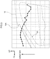
Fig. 5 is a graph showing generated load during a front collision of a vehicle equipped with the front pillar structure according to the present exemplary embodiment. -
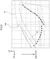
Fig. 6 is a graph showing generated moment during the front collision of the vehicle equipped with the front pillar structure according to the present exemplary embodiment. -
Fig. 7 is a side view showing a front pillar structure according to a comparative example. - Herebelow, an exemplary embodiment relating to the present disclosure is described in detail in accordance with the drawings. For convenience of description, the arrow UP that is shown where appropriate in the drawings indicates a vehicle upper direction, the arrow FR indicates a vehicle front direction, and the arrow RH indicates a vehicle right direction. Thus, in the following descriptions, where the directions upper and lower, front and rear, and left and right are recited without being particularly specified, the same represent upper and lower in the vehicle vertical direction, front and rear in the vehicle front-and-rear direction, and left and right in the vehicle left-and-right direction (the vehicle width direction).
- As shown in
Fig. 2 , a front windshield glass (below referred to as "the front glass") 18 is provided at avehicle 12. Thefront glass 18 is inclined to the vehicle rear side toward the vehicle upper side and separates the inside of a passenger compartment from the outside of the passenger compartment. An upper end portion of thefront glass 18 is connected to a front header (not shown in the drawings) that is disposed at afront end portion 16A of aroof panel 16 that structures a roof 14 (seeFig. 1 ). - As shown in
Fig. 3 , aroof side rail 22 is disposed at each vehicle width direction outer side end portion of theroof 14. Theroof side rail 22 extends in the vehicle front-and-rear direction. Theroof side rail 22 is formed in a chamber shape by respective flange portions of a rail inner panel (not shown in the drawings) and a railouter panel 24 being joined together. A side member outer panel (below referred to as "the side member outer") 26 is disposed at the vehicle width direction outer side of the railouter panel 24. - As shown in
Fig. 1 , a left and right pair of front pillars (below referred to as "the A pillars") 20 are provided at the vehicle width direction outer sides of thefront glass 18. Afront pillar structure 10 according to the present exemplary embodiment is employed at eachA pillar 20. The left and right pair ofA pillars 20 extend along respective vehicle width direction outerside end portions 18A (seeFig. 2 ) of thefront glass 18, with length directions of theA pillars 20 substantially in the vehicle vertical direction. - That is, the left and right pair of
A pillars 20 are each inclined to the vehicle rear side toward the vehicle upper side. TheA pillars 20 have the same structures at the left side (for example, a front passenger seat side) and the right side (for example, a driver seat side) with left-and-right mirror symmetry. Accordingly, only theA pillar 20 at the right side is described below. - As shown in
Fig. 2 , theA pillar 20 includes afront column 30 that serves as a front side pillar frame member and arear column 40 that serves as a rear side pillar frame member. Thefront column 30 extends substantially in the vehicle vertical direction. Thefront column 30 includes a front side pillarouter panel 32 fabricated of steel plate and a front side pillarinner panel 34 fabricated of steel plate. - The
front column 30 is formed in a chamber shape by the front side pillarouter panel 32 and the front side pillarinner panel 34. That is, the front side pillarinner panel 34 is provided substantially at the vehicle rear side of the front side pillarouter panel 32 to oppose the front side pillarouter panel 32, and the front side pillarouter panel 32 and front side pillarinner panel 34 are joined together by linear welding such as arc welding, laser welding or the like. - To describe this in more detail, an outer
side flange portion 32A is a vehicle width direction outer side end portion of the front side pillarouter panel 32, and an outerside flange portion 34A is a vehicle width direction outer side end portion of the front side pillarinner panel 34. The outerside flange portion 32A and outerside flange portion 34A are superposed with one another and the superposed portions are linearly welded. That is, a predetermined gap in the length direction is left open between the outerside flange portion 32A and the outerside flange portion 34A, and plurallinear weld portions 36 are formed in the gap. - Meanwhile, an inner
side flange portion 32B is a vehicle width direction inner side end portion of the front side pillarouter panel 32, and an innerside flange portion 34B is a vehicle width direction inner side end portion of the front side pillarinner panel 34. The innerside flange portion 32B and innerside flange portion 34B are superposed with one another and the superposed portions are linearly welded. That is, a predetermined gap in the length direction is left open between the innerside flange portion 32B and the innerside flange portion 34B, and plurallinear weld portions 38 are formed in the gap. - The vehicle width direction outer
side end portion 18A of thefront glass 18 is joined to thefront column 30 via aurethane adhesive 52 and acushioning rubber 54. To describe this in more detail, aflat surface portion 32D that is oriented to the vehicle front side is formed at the front side pillarouter panel 32 structuring thefront column 30. The outerside flange portion 32A is continuous with the vehicle width direction outer side of theflat surface portion 32D. In other words, the outerside flange portion 32A is a portion of theflat surface portion 32D. - The
urethane adhesive 52 is provided at aninner face 18B of the vehicle width direction outerside end portion 18A of thefront glass 18. Theinner face 18B is oriented to the passenger compartment side. The cushioningrubber 54 is provided for positioning at the vehicle width direction inner side of theinner face 18B relative to theurethane adhesive 52. The cushioningrubber 54 is provided in contact with theurethane adhesive 52. Thus, while the vehicle width direction outerside end portion 18A of thefront glass 18 is positioned relative to theflat surface portion 32D of the front side pillarouter panel 32 by the cushioningrubber 54, the vehicle width direction outerside end portion 18A is joined to theflat surface portion 32D from the vehicle front side thereof by theurethane adhesive 52. - The
rear column 40 is disposed substantially at the vehicle rear side of thefront column 30. That is, therear column 40 is disposed substantially in the vehicle rear direction from thefront column 30 with a predetermined gap therebetween and extends substantially in parallel with the front column 30 (substantially in the vehicle vertical direction). Therear column 40 includes a rear side pillarouter panel 42 fabricated of steel plate and a rear side pillarinner panel 44 fabricated of steel plate. - The
rear column 40 is formed in a chamber shape by the rear side pillarouter panel 42 and the rear side pillarinner panel 44. That is, the rear side pillarinner panel 44 is provided substantially at the vehicle width direction inner side of the rear side pillarouter panel 42 to oppose the rear side pillarouter panel 42, and the rear side pillarouter panel 42 and rear side pillarinner panel 44 are joined together by linear welding and spot welding such as arc welding, laser welding or the like. - To describe this in more detail, a front
side flange portion 42A is a vehicle front side end portion of the rear side pillarouter panel 42, and a frontside flange portion 44A is a vehicle front side end portion of the rear side pillarinner panel 44. The frontside flange portion 42A and frontside flange portion 44A are superposed with one another and the superposed portions are linearly welded. That is, a predetermined gap in the length direction is left open between the frontside flange portion 42A and the frontside flange portion 44A, and plurallinear weld portions 46 are formed in the gap. - Meanwhile, a rear
side flange portion 42B is a vehicle rear side end portion of the rear side pillarouter panel 42, and a rearside flange portion 44B is a vehicle rear side end portion of the rear side pillarinner panel 44. The rearside flange portion 42B and rearside flange portion 44B are superposed with one another and the superposed portions are spot welded. That is, a predetermined gap in the length direction is left open between the rearside flange portion 42B and the rearside flange portion 44B, and pluralspot weld portions 48 are formed in the gap (seeFig. 3 ). - The side member outer 26 is disposed at the vehicle width direction outer side of the rear side pillar
outer panel 42. A frontside flange portion 26A of the side member outer 26 covers the rear side pillarouter panel 42. The frontside flange portion 26A is linearly welded to a wall face at the front side of the rear side pillarouter panel 42 by arc welding, laser welding or the like. That is,linear weld portions 47 are formed at the frontside flange portion 26A and the wall face at the front side of the rear side pillarouter panel 42. - A rear
side flange portion 26B of the side member outer 26 covers the rear side pillarouter panel 42. The rearside flange portion 26B is spot welded to the rearside flange portion 42B. The rearside flange portion 26B of the side member outer 26, the rearside flange portion 42B and the rearside flange portion 44B are superposed with one another, and an openingweatherstrip 66 fabricated of resin (fabricated of rubber) is attached to the rearside flange portion 26B, rearside flange portion 42B and rearside flange portion 44B by being tightly fitted thereto substantially from the vehicle rear side. - An A
pillar glass 50 that serves as a transparent member spans between thefront column 30 and therear column 40, viapillar glass moldings rubber 54 and theurethane adhesive 52. TheA pillar glass 50 is a transparent window member with a plate thickness direction substantially in the vehicle width direction. In the side view (seeFig. 1 ), theA pillar glass 50 is inclined to the vehicle rear side toward the vehicle upper side. - The
pillar glass molding 56, which is fabricated of resin (fabricated of rubber), is integrally attached to a front end portion of theA pillar glass 50. Aprotrusion portion 56B that serves as a positioning portion is integrally formed at the vehicle width direction inner side of awall face 56A of thepillar glass molding 56 that is oriented to the passenger compartment side thereof. Another of theurethane adhesive 52 is attached at the vehicle width direction outer side of theprotrusion portion 56B. - The
pillar glass molding 57, which is fabricated of resin (fabricated of rubber), is integrally attached to a rear end portion of theA pillar glass 50. Still another of theurethane adhesive 52 is attached to the vehicle rear side of awall face 57A of thepillar glass molding 57 that is oriented to the vehicle rear side. Another of the cushioningrubber 54 is attached to the vehicle front side of thewall face 57A. - Accordingly, at the front end portion of the
A pillar glass 50, while thepillar glass molding 56 is positioned at the outerside flange portion 32A (theflat surface portion 32D) from the vehicle front side by theprotrusion portion 56B, thepillar glass molding 56 is attached to thefront column 30 by being joined by theurethane adhesive 52. At the rear end portion of theA pillar glass 50, while thepillar glass molding 57 is positioned at the frontside flange portion 42A from the vehicle width direction outer side by the cushioningrubber 54, thepillar glass molding 57 is joined to the frontside flange portion 26A of the side member outer 26 by theurethane adhesive 52, and theglass molding 57 is attached to therear column 40 via the frontside flange portion 26A of the side member outer 26. - A
molding 19 fabricated of resin (fabricated of rubber) that serves as a sealing member is provided at the vehicle width direction outerside end portion 18A of thefront glass 18. A vehicle width direction outerside end portion 19A of themolding 19 is abutted against thepillar glass molding 56 in a resiliently deformed state (with a predetermined pressure). Thus, the ingression of rainwater and the like between theA pillar glass 50 and thefront glass 18 is prevented by themolding 19 being provided between the vehicle width direction outerside end portion 18A of thefront glass 18 and thepillar glass molding 56. - A
door frame 28 of a front door (not shown in the drawings) is disposed at the vehicle width direction outer side of the rear side pillarouter panel 42. Adoor weatherstrip 67 is provided at the vehicle front side of thedoor frame 28. Aglass run 68 is provided at the vehicle rear side of thedoor frame 28. TheA pillar glass 50 is not limited to being formed of glass but may be formed of, for example, a transparent fiber-reinforced resin or the like. - A pillar garnishes 58 are provided at the vehicle width direction inner sides of the
front column 30 and therear column 40. The A pillar garnishes 58 are fabricated of resin. The A pillar garnishes 58 include a frontside pillar garnish 60 provided at the passenger compartment side of thefront column 30 and a rearside pillar garnish 70 provided at the passenger compartment side of therear column 40. - The front
side pillar garnish 60 includes amain body portion 62 that extends along thefront column 30 substantially in the vehicle vertical direction. A cross section of themain body portion 62 intersecting the length direction thereof (in a plan sectional view) is formed substantially in a "U" shape that opens toward the vehicle front side. Themain body portion 62 covers thefront column 30 from the passenger compartment side thereof in a non-contacting state. -
Plural clips 64 are provided at an inner face of themain body portion 62, spaced by a predetermined spacing along the length direction of themain body portion 62. Eachclip 64 is formed substantially in an arrowhead shape including awide breadth portion 64A at a distal end side thereof. The clips 64 (wide breadth portions 64A) are formed to be resiliently deformable in a direction intersecting the projection direction thereof. The clips 64 (wide breadth portions 64A) project from the inner face of themain body portion 62 so as to be opposable with the front side pillarinner panel 34. - Penetrating
holes 35 are formed in the front side pillarinner panel 34. Inner breadths of the penetratingholes 35 are formed to be a little smaller than outer breadths of thewide breadth portions 64A. Thus, the frontside pillar garnish 60 is attached to thefront column 30 by thewide breadth portions 64A of theclips 64 being resiliently deformed and inserted into the penetratingholes 35, after which thewide breadth portions 64A restore shape. - The rear
side pillar garnish 70 includes amain body portion 72 that extends along therear column 40 substantially in the vehicle vertical direction. A cross section of themain body portion 72 intersecting the length direction thereof (in a plan sectional view) is formed substantially in a "U" shape that opens toward the vehicle width direction outer side. Themain body portion 72 covers therear column 40 from the passenger compartment side thereof in a non-contacting state. - Clips (not shown in the drawings) similar to the
clips 64 described above are provided at an inner face of the rearside pillar garnish 70. The rearside pillar garnish 70 is attached to therear column 40 by these clips. Awire harness 74 is arranged between therear column 40 and the rearside pillar garnish 70. - As shown in
Fig. 3 , at an upper end portion of thefront column 30, anupper end portion 32C of the front side pillarouter panel 32 extends further to the vehicle rear side than anupper end portion 34C of the front side pillarinner panel 34. At an upper end portion of therear column 40, anupper end portion 42C of the rear side pillarouter panel 42 extends further to the vehicle rear side than anupper end portion 44C of the rear side pillarinner panel 44. - The
upper end portion 32C of the front side pillarouter panel 32 and theupper end portion 42C of the rear side pillarouter panel 42 are each joined by spot welding to the railouter panel 24, at the vehicle rear side relative to thefront end portion 16A of theroof panel 16 in side view but at the vehicle front side relative to an upperend edge portion 80A at the vehicle front side of a center pillar (below referred to as "the B pillar") 80 (seeFig. 1 ). - To describe this in more detail, a first joining
portion 82 and a second joiningportion 84 are formed at the railouter panel 24 between thefront end portion 16A of theroof panel 16 and the upperend edge portion 80A of theB pillar 80. The first joiningportion 82 is formed by theupper end portion 32C of the front side pillarouter panel 32 being bonded (joined) to the railouter panel 24 by spot welds at plural locations. The second joiningportion 84 is formed by theupper end portion 42C of the rear side pillarouter panel 42 being bonded (joined) to the railouter panel 24 by spot welds at plural locations. - It is more preferable if the first joining
portion 82 and second joiningportion 84 are formed at a substantially central portion in the vehicle front-and-rear direction of the rail outer panel 24 (a substantial middle position) between thefront end portion 16A of the roof panel 16 (or arear end portion 76A of abracket 76 that is described below) and the upperend edge portion 80A of theB pillar 80. - The
upper end portion 32C of the front side pillarouter panel 32 is joined to the rail outer panel 24 (at the first joining portion 82) by spot welding at two locations, and theupper end portion 42C of the rear side pillarouter panel 42 is joined to the rail outer panel 24 (at the second joining portion 84) by spot welding at three locations. - As shown in
Fig. 3 , thefront end portion 16A of theroof panel 16 is disposed at substantially the same position in the vehicle front-and-rear direction as an upperend edge portion 50A of theA pillar glass 50. That is, proceeding from the vehicle front side toward the vehicle rear side, a region in which theA pillar glass 50 terminates is also a region in which theroof 14 begins. As shown inFig. 1 , the upperend edge portion 80A at the vehicle front side of theB pillar 80 can also be regarded as a corner portion 86 (a vertex portion) at the vehicle front side where theB pillar 80 and theroof side rail 22 intersect. - As shown in
Fig. 4 , thebracket 76 may serve as a connecting member spanning between thefront column 30 and the rear column 40 (Fig. 1 depicts a structure in which thebracket 76 is included). Thebracket 76 connects thefront column 30 with therear column 40 in a region in which at least therear end portion 76A of thebracket 76 overlaps in plan view with thefront end portion 16A of theroof panel 16 in the vehicle front-and-rear direction. Thebracket 76 covers the upperend edge portion 50A (seeFig. 3 ) of theA pillar glass 50 from the vehicle width direction inner side thereof. -
Slit portions 78 with length directions in the front-and-rear direction are formed at two locations in an upper portion of thebracket 76. Peripheral edge portions of theslit portions 78 are joined to the front side pillarinner panel 34 of thefront column 30 by linear welding such as arc welding, laser welding or the like. A lowerend edge portion 76B of thebracket 76 is bonded to the rear side pillarinner panel 44 of therear column 40 by linear welding such as arc welding, laser welding or the like. Anupper end portion 76C of thebracket 76 is bonded to an upperside flange portion 26C of the side member outer 26 by spot welding at three locations. - Now, operation of the
front pillar structure 10 according to the present exemplary embodiment with the structure described above is described. - First, a
front pillar structure 100 according to a comparative example, which is shown inFig. 7 , is described. At anA pillar 120, aroof side rail 122 is disposed at a vehicle width direction outer side of aroof panel 116. As shown inFig. 7 , acorner portion 186 with an obtuse angle shape in side view is formed by a front end portion of theroof side rail 122 and anupper end portion 140C of arear column 140. - An
upper end portion 130C of afront column 130 is joined to the roof side rail 122 (in a vicinity of the corner portion 186) at the vehicle front side relative to afront end portion 116A of theroof panel 116. That is, joiningportions upper end portion 130C of thefront column 130 and theupper end portion 140C of therear column 140 to theroof side rail 122 are both formed at the vehicle front side relative to thefront end portion 116A of theroof panel 116. - During a front collision of the vehicle 12 (when a load is applied from the vehicle front side), a generated load at the vehicle front side relative to the corner portion 186 (and the
front end portion 116A of the roof panel 116) is large, as a result which a generated moment is large (seeFig. 5 andFig. 6 ). Consequently, during the front collision of thevehicle 12, pillar-bending may occur at theA pillar 120, with the origin of the bending being thecorner portion 186. - In contrast, in the
front pillar structure 10 according to the present exemplary embodiment, as shown inFig. 3 , theupper end portion 32C of the front side pillarouter panel 32 that structures thefront column 30 and theupper end portion 42C of the rear side pillarouter panel 42 that structures therear column 40 are both joined to the railouter panel 24 of theroof side rail 22 at the vehicle rear side relative to thefront end portion 16A of theroof panel 16. - In other words, the first joining
portion 82 at which theupper end portion 32C of the front side pillarouter panel 32 is joined to the railouter panel 24 and the second joiningportion 84 at which theupper end portion 42C of the rear side pillarouter panel 42 is joined to the railouter panel 24 are formed at the vehicle rear side relative to thefront end portion 16A of theroof panel 16. - As illustrated in
Fig. 5 andFig. 6 , a generated load when a load is applied from the vehicle front side is smaller at the vehicle rear side relative to thefront end portion 16A of theroof panel 16 than at the vehicle front side, the opposite side of thefront end portion 16A. Consequently, a generated moment is also smaller at the vehicle rear side (with a decreasing trend). Therefore, during a front collision of thevehicle 12, an occurrence of pillar-bending from the first joiningportion 82 and the second joiningportion 84 may be suppressed (endurance of theA pillar 20 may be improved) even at the first joiningportion 82 and second joiningportion 84 at which stresses tend to concentrate. - The same applies in a mode in which the
bracket 76 is provided connecting thefront column 30 with therear column 40, as shown inFig. 4 . That is, thebracket 76 is provided at a location at which at least therear end portion 76A overlaps in plan view with thefront end portion 16A of theroof panel 16 in the vehicle front-and-rear direction, and the first joiningportion 82 and second joiningportion 84 are formed at the vehicle rear side relative to therear end portion 76A of thebracket 76. - Therefore, similarly to the above description, a generated load when a load is applied from the vehicle front side is smaller at the vehicle rear side relative to the
rear end portion 76A of thebracket 76 than at the vehicle front side, the opposite side of therear end portion 76A, and consequently a generated moment is smaller at the vehicle rear side (with a decreasing trend). In addition, stiffness at the upper end portion of theA pillar 20 may be improved by thebracket 76. Therefore, an occurrence of pillar-bending from the first joiningportion 82 and the second joiningportion 84 during a front collision of thevehicle 12 may be suppressed (endurance of theA pillar 20 may be further improved). - As shown in
Fig. 1 , in thefront pillar structure 10 according to the present exemplary embodiment, the first joiningportion 82 and second joiningportion 84 are formed at the vehicle front side relative to the upperend edge portion 80A of theB pillar 80. In other words, the first joiningportion 82 and second joiningportion 84 are formed between thefront end portion 16A of theroof panel 16 orrear end portion 76A of thebracket 76 and the upperend edge portion 80A of theB pillar 80. - Accordingly, lengths of the
front column 30 and therear column 40 may be reduced compared to, for example, a structure in which the first joiningportion 82 and second joiningportion 84 are formed at the vehicle rear side relative to the upperend edge portion 80A of the B pillar 80 (i.e., thefront column 30 andrear column 40 are elongated to the vehicle rear side beyond the upperend edge portion 80A of the B pillar 80). Thus, an increase in weight of thevehicle 12 may be suppressed. - As mentioned above, it is preferable if the first joining
portion 82 and the second joiningportion 84 are formed at a substantially central portion in the vehicle front-and-rear direction of the rail outer panel 24 (a substantial middle position) between thefront end portion 16A of theroof panel 16 orrear end portion 76A of thebracket 76 and the upperend edge portion 80A of the B pillar 80 (seeFig. 1 ). According to this structure, a good balance may be found between suppressing an occurrence of pillar-bending from the first joiningportion 82 and second joiningportion 84 and suppressing an increase in weight of thevehicle 12. - The
A pillar 20 structuring thefront pillar structure 10 according to the present exemplary embodiment is provided with the transparentA pillar glass 50. Therefore, a benefit is provided in that a driver (a vehicle occupant) may view conditions at the outer side of theA pillar 20 through theA pillar glass 50 between the front side pillar garnish 60 (the front column 30) and the rear side pillar garnish 70 (the rear column 40). - Hereabove, the
front pillar structure 10 according to the present exemplary embodiment has been described in accordance with the attached drawings. However, thefront pillar structure 10 according to the present exemplary embodiment is not limited to the illustrated structure; suitable design modifications may be applied within the scope of the present disclosure. For example, the numbers of spot welds constituting the first joiningportion 82 and the second joiningportion 84 are not limited to the illustrated numbers.
Claims (5)
- A front pillar structure comprising:a front side pillar frame member (30) and a rear side pillar frame member (40) that structure a front pillar (20);a transparent member (50) that spans between the front side pillar frame member (30) and the rear side pillar frame member (40) and structures the front pillar (20);a first joining portion (82) at which an upper end portion of the front side pillar frame member (30) is joined to a roof side rail (22) that is disposed at a vehicle width direction outer side of a roof panel (16); anda second joining portion (84) at which an upper end portion of the rear side pillar frame member (40) is joined to the roof side rail (22), wherein the first joining portion (82) and the second joining portion (84) are formed at the vehicle rear side relative to a front end portion of the roof panel (16).
- A front pillar structure according to claim 1, further comprising:
a connecting member (76) that connects the front side pillar frame member (30) with the rear side pillar frame member (40), at a location at which at least a vehicle rear side end portion of the connecting member (76) overlaps in the vehicle front-and-rear direction with a front end portion of the roof panel (16), wherein the first joining portion (82) and the second joining portion (84) are formed at the vehicle rear side relative to the connecting member (76). - The front pillar structure according to claim 1 or claim 2, wherein the first joining portion (82) and the second joining portion (84) are formed at the vehicle front side relative to an upper end edge portion at the vehicle front side of a center pillar (80).
- The front pillar structure according to claim 1, wherein the first joining portion (82) and the second joining portion (84) are formed at a substantially central portion in the vehicle front-and-rear direction of the roof side rail (22) between the front end portion of the roof panel (16) and an upper end edge portion at the vehicle front side of a center pillar (80).
- The front pillar structure according to claim 2, wherein the first joining portion (82) and the second joining portion (84) are formed at a substantially central portion in the vehicle front-and-rear direction of the roof side rail (22) between the connecting member (76) and an upper end edge portion at the vehicle front side of a center pillar (80).
Applications Claiming Priority (1)
| Application Number | Priority Date | Filing Date | Title |
|---|---|---|---|
| JP2018226522A JP7110952B2 (en) | 2018-12-03 | 2018-12-03 | Front pillar structure |
Publications (2)
| Publication Number | Publication Date |
|---|---|
| EP3663169A1 true EP3663169A1 (en) | 2020-06-10 |
| EP3663169B1 EP3663169B1 (en) | 2022-07-06 |
Family
ID=68699260
Family Applications (1)
| Application Number | Title | Priority Date | Filing Date |
|---|---|---|---|
| EP19211704.2A Active EP3663169B1 (en) | 2018-12-03 | 2019-11-27 | Front pillar structure |
Country Status (4)
| Country | Link |
|---|---|
| US (1) | US11148726B2 (en) |
| EP (1) | EP3663169B1 (en) |
| JP (1) | JP7110952B2 (en) |
| CN (1) | CN111252144B (en) |
Families Citing this family (2)
| Publication number | Priority date | Publication date | Assignee | Title |
|---|---|---|---|---|
| JP7074021B2 (en) * | 2018-10-26 | 2022-05-24 | トヨタ自動車株式会社 | Pillar structure for vehicles |
| CN114620144A (en) * | 2022-02-11 | 2022-06-14 | 浙江零跑科技股份有限公司 | Glass fixing structure for B column of frameless vehicle door |
Citations (4)
| Publication number | Priority date | Publication date | Assignee | Title |
|---|---|---|---|---|
| US4807925A (en) * | 1986-02-13 | 1989-02-28 | Mazda Motor Corporation | Front vehicle body structure |
| GB2476350A (en) * | 2009-12-21 | 2011-06-22 | Gm Global Tech Operations Inc | A motor vehicle featuring a structural car body column with a structural component and a method for connecting a structural component of a structural car body |
| JP2013184659A (en) | 2012-03-09 | 2013-09-19 | Toyota Motor Corp | Vehicle side structure |
| EP3511230A1 (en) * | 2018-01-16 | 2019-07-17 | Toyota Jidosha Kabushiki Kaisha | Vehicle pillar structure and vehicle side portion structure |
Family Cites Families (11)
| Publication number | Priority date | Publication date | Assignee | Title |
|---|---|---|---|---|
| KR100356669B1 (en) * | 1996-12-10 | 2003-01-24 | 기아자동차주식회사 | Joining structure of roof panel and a-pillar of electric vehicle |
| JP3324493B2 (en) | 1998-02-19 | 2002-09-17 | トヨタ車体株式会社 | Car front pillar structure |
| JP2001301653A (en) * | 2000-04-25 | 2001-10-31 | Nissan Motor Co Ltd | Automobile body assembly method and body structure |
| DE102007014116A1 (en) * | 2007-03-23 | 2008-09-25 | Ford Global Technologies, LLC, Dearborn | Column, particularly A-column for use as part of body structure of motor vehicle, has hollow profile with closed cross section, where hollow profile is connected to body structure with intended connection plate |
| GB2479363A (en) | 2010-04-07 | 2011-10-12 | Gm Global Tech Operations Inc | Partially transparent vehicle body component |
| JP2012051563A (en) * | 2011-08-29 | 2012-03-15 | Fujio Miyazaki | Safety confirmation device |
| JP5400862B2 (en) | 2011-11-25 | 2014-01-29 | 本田技研工業株式会社 | Body side structure |
| JP6073280B2 (en) | 2014-11-11 | 2017-02-01 | 本田技研工業株式会社 | Body superstructure |
| JP6477286B2 (en) | 2015-06-22 | 2019-03-06 | トヨタ自動車株式会社 | Pillar structure for automobile |
| JP6447535B2 (en) * | 2016-02-22 | 2019-01-09 | トヨタ自動車株式会社 | Pillar structure for vehicles |
| JP6794837B2 (en) * | 2017-01-12 | 2020-12-02 | スズキ株式会社 | Body side structure |
-
2018
- 2018-12-03 JP JP2018226522A patent/JP7110952B2/en active Active
-
2019
- 2019-10-29 CN CN201911036095.1A patent/CN111252144B/en active Active
- 2019-11-07 US US16/676,437 patent/US11148726B2/en active Active
- 2019-11-27 EP EP19211704.2A patent/EP3663169B1/en active Active
Patent Citations (4)
| Publication number | Priority date | Publication date | Assignee | Title |
|---|---|---|---|---|
| US4807925A (en) * | 1986-02-13 | 1989-02-28 | Mazda Motor Corporation | Front vehicle body structure |
| GB2476350A (en) * | 2009-12-21 | 2011-06-22 | Gm Global Tech Operations Inc | A motor vehicle featuring a structural car body column with a structural component and a method for connecting a structural component of a structural car body |
| JP2013184659A (en) | 2012-03-09 | 2013-09-19 | Toyota Motor Corp | Vehicle side structure |
| EP3511230A1 (en) * | 2018-01-16 | 2019-07-17 | Toyota Jidosha Kabushiki Kaisha | Vehicle pillar structure and vehicle side portion structure |
Also Published As
| Publication number | Publication date |
|---|---|
| EP3663169B1 (en) | 2022-07-06 |
| JP2020090112A (en) | 2020-06-11 |
| CN111252144A (en) | 2020-06-09 |
| US11148726B2 (en) | 2021-10-19 |
| US20200172168A1 (en) | 2020-06-04 |
| CN111252144B (en) | 2022-06-07 |
| JP7110952B2 (en) | 2022-08-02 |
Similar Documents
| Publication | Publication Date | Title |
|---|---|---|
| JP7156451B2 (en) | Front pillar structure | |
| CN105377674B (en) | Body top section structure | |
| US10053154B2 (en) | Vehicle side structure | |
| JP6610595B2 (en) | Pillar structure for vehicles | |
| JP7074029B2 (en) | Pillar structure for vehicles | |
| CN109747719B (en) | Column structure for automobile | |
| JP2017154706A (en) | Vehicular pillar structure | |
| CN112455546A (en) | Subframe for vehicle | |
| EP3663169B1 (en) | Front pillar structure | |
| US8398157B2 (en) | Pillar reduction by outer panel cut | |
| CN111434569A (en) | Lower structure of vehicle body | |
| JP2019084887A (en) | Pillar structure for automobile | |
| US11548554B2 (en) | Vehicle rear portion structure | |
| US10676045B1 (en) | Vehicle assembly | |
| US20100301636A1 (en) | Vehicle body front portion structure | |
| EP3653445B1 (en) | Front pillar structure | |
| US9764774B2 (en) | Vehicle body front portion structure | |
| CN100371202C (en) | body frame structure | |
| JP6107209B2 (en) | Roof side rail structure | |
| JP7358922B2 (en) | Vehicle front structure | |
| US20250108865A1 (en) | Vehicle body structure | |
| JP7750793B2 (en) | Front pillar upper structure | |
| JP4127226B2 (en) | Body frame structure |
Legal Events
| Date | Code | Title | Description |
|---|---|---|---|
| PUAI | Public reference made under article 153(3) epc to a published international application that has entered the european phase |
Free format text: ORIGINAL CODE: 0009012 |
|
| STAA | Information on the status of an ep patent application or granted ep patent |
Free format text: STATUS: REQUEST FOR EXAMINATION WAS MADE |
|
| 17P | Request for examination filed |
Effective date: 20191127 |
|
| AK | Designated contracting states |
Kind code of ref document: A1 Designated state(s): AL AT BE BG CH CY CZ DE DK EE ES FI FR GB GR HR HU IE IS IT LI LT LU LV MC MK MT NL NO PL PT RO RS SE SI SK SM TR |
|
| AX | Request for extension of the european patent |
Extension state: BA ME |
|
| GRAP | Despatch of communication of intention to grant a patent |
Free format text: ORIGINAL CODE: EPIDOSNIGR1 |
|
| STAA | Information on the status of an ep patent application or granted ep patent |
Free format text: STATUS: GRANT OF PATENT IS INTENDED |
|
| INTG | Intention to grant announced |
Effective date: 20220406 |
|
| GRAS | Grant fee paid |
Free format text: ORIGINAL CODE: EPIDOSNIGR3 |
|
| GRAA | (expected) grant |
Free format text: ORIGINAL CODE: 0009210 |
|
| STAA | Information on the status of an ep patent application or granted ep patent |
Free format text: STATUS: THE PATENT HAS BEEN GRANTED |
|
| AK | Designated contracting states |
Kind code of ref document: B1 Designated state(s): AL AT BE BG CH CY CZ DE DK EE ES FI FR GB GR HR HU IE IS IT LI LT LU LV MC MK MT NL NO PL PT RO RS SE SI SK SM TR |
|
| REG | Reference to a national code |
Ref country code: AT Ref legal event code: REF Ref document number: 1502693 Country of ref document: AT Kind code of ref document: T Effective date: 20220715 Ref country code: CH Ref legal event code: EP |
|
| REG | Reference to a national code |
Ref country code: DE Ref legal event code: R096 Ref document number: 602019016651 Country of ref document: DE |
|
| REG | Reference to a national code |
Ref country code: IE Ref legal event code: FG4D |
|
| REG | Reference to a national code |
Ref country code: LT Ref legal event code: MG9D |
|
| REG | Reference to a national code |
Ref country code: NL Ref legal event code: MP Effective date: 20220706 |
|
| PGFP | Annual fee paid to national office [announced via postgrant information from national office to epo] |
Ref country code: FR Payment date: 20221010 Year of fee payment: 4 |
|
| PG25 | Lapsed in a contracting state [announced via postgrant information from national office to epo] |
Ref country code: SE Free format text: LAPSE BECAUSE OF FAILURE TO SUBMIT A TRANSLATION OF THE DESCRIPTION OR TO PAY THE FEE WITHIN THE PRESCRIBED TIME-LIMIT Effective date: 20220706 Ref country code: RS Free format text: LAPSE BECAUSE OF FAILURE TO SUBMIT A TRANSLATION OF THE DESCRIPTION OR TO PAY THE FEE WITHIN THE PRESCRIBED TIME-LIMIT Effective date: 20220706 Ref country code: PT Free format text: LAPSE BECAUSE OF FAILURE TO SUBMIT A TRANSLATION OF THE DESCRIPTION OR TO PAY THE FEE WITHIN THE PRESCRIBED TIME-LIMIT Effective date: 20221107 Ref country code: NO Free format text: LAPSE BECAUSE OF FAILURE TO SUBMIT A TRANSLATION OF THE DESCRIPTION OR TO PAY THE FEE WITHIN THE PRESCRIBED TIME-LIMIT Effective date: 20221006 Ref country code: NL Free format text: LAPSE BECAUSE OF FAILURE TO SUBMIT A TRANSLATION OF THE DESCRIPTION OR TO PAY THE FEE WITHIN THE PRESCRIBED TIME-LIMIT Effective date: 20220706 Ref country code: LV Free format text: LAPSE BECAUSE OF FAILURE TO SUBMIT A TRANSLATION OF THE DESCRIPTION OR TO PAY THE FEE WITHIN THE PRESCRIBED TIME-LIMIT Effective date: 20220706 Ref country code: LT Free format text: LAPSE BECAUSE OF FAILURE TO SUBMIT A TRANSLATION OF THE DESCRIPTION OR TO PAY THE FEE WITHIN THE PRESCRIBED TIME-LIMIT Effective date: 20220706 Ref country code: FI Free format text: LAPSE BECAUSE OF FAILURE TO SUBMIT A TRANSLATION OF THE DESCRIPTION OR TO PAY THE FEE WITHIN THE PRESCRIBED TIME-LIMIT Effective date: 20220706 Ref country code: ES Free format text: LAPSE BECAUSE OF FAILURE TO SUBMIT A TRANSLATION OF THE DESCRIPTION OR TO PAY THE FEE WITHIN THE PRESCRIBED TIME-LIMIT Effective date: 20220706 |
|
| REG | Reference to a national code |
Ref country code: AT Ref legal event code: MK05 Ref document number: 1502693 Country of ref document: AT Kind code of ref document: T Effective date: 20220706 |
|
| PG25 | Lapsed in a contracting state [announced via postgrant information from national office to epo] |
Ref country code: PL Free format text: LAPSE BECAUSE OF FAILURE TO SUBMIT A TRANSLATION OF THE DESCRIPTION OR TO PAY THE FEE WITHIN THE PRESCRIBED TIME-LIMIT Effective date: 20220706 Ref country code: IS Free format text: LAPSE BECAUSE OF FAILURE TO SUBMIT A TRANSLATION OF THE DESCRIPTION OR TO PAY THE FEE WITHIN THE PRESCRIBED TIME-LIMIT Effective date: 20221106 Ref country code: HR Free format text: LAPSE BECAUSE OF FAILURE TO SUBMIT A TRANSLATION OF THE DESCRIPTION OR TO PAY THE FEE WITHIN THE PRESCRIBED TIME-LIMIT Effective date: 20220706 Ref country code: GR Free format text: LAPSE BECAUSE OF FAILURE TO SUBMIT A TRANSLATION OF THE DESCRIPTION OR TO PAY THE FEE WITHIN THE PRESCRIBED TIME-LIMIT Effective date: 20221007 |
|
| REG | Reference to a national code |
Ref country code: DE Ref legal event code: R097 Ref document number: 602019016651 Country of ref document: DE |
|
| PG25 | Lapsed in a contracting state [announced via postgrant information from national office to epo] |
Ref country code: SM Free format text: LAPSE BECAUSE OF FAILURE TO SUBMIT A TRANSLATION OF THE DESCRIPTION OR TO PAY THE FEE WITHIN THE PRESCRIBED TIME-LIMIT Effective date: 20220706 Ref country code: RO Free format text: LAPSE BECAUSE OF FAILURE TO SUBMIT A TRANSLATION OF THE DESCRIPTION OR TO PAY THE FEE WITHIN THE PRESCRIBED TIME-LIMIT Effective date: 20220706 Ref country code: DK Free format text: LAPSE BECAUSE OF FAILURE TO SUBMIT A TRANSLATION OF THE DESCRIPTION OR TO PAY THE FEE WITHIN THE PRESCRIBED TIME-LIMIT Effective date: 20220706 Ref country code: CZ Free format text: LAPSE BECAUSE OF FAILURE TO SUBMIT A TRANSLATION OF THE DESCRIPTION OR TO PAY THE FEE WITHIN THE PRESCRIBED TIME-LIMIT Effective date: 20220706 Ref country code: AT Free format text: LAPSE BECAUSE OF FAILURE TO SUBMIT A TRANSLATION OF THE DESCRIPTION OR TO PAY THE FEE WITHIN THE PRESCRIBED TIME-LIMIT Effective date: 20220706 |
|
| PLBE | No opposition filed within time limit |
Free format text: ORIGINAL CODE: 0009261 |
|
| STAA | Information on the status of an ep patent application or granted ep patent |
Free format text: STATUS: NO OPPOSITION FILED WITHIN TIME LIMIT |
|
| PG25 | Lapsed in a contracting state [announced via postgrant information from national office to epo] |
Ref country code: SK Free format text: LAPSE BECAUSE OF FAILURE TO SUBMIT A TRANSLATION OF THE DESCRIPTION OR TO PAY THE FEE WITHIN THE PRESCRIBED TIME-LIMIT Effective date: 20220706 Ref country code: EE Free format text: LAPSE BECAUSE OF FAILURE TO SUBMIT A TRANSLATION OF THE DESCRIPTION OR TO PAY THE FEE WITHIN THE PRESCRIBED TIME-LIMIT Effective date: 20220706 |
|
| 26N | No opposition filed |
Effective date: 20230411 |
|
| P01 | Opt-out of the competence of the unified patent court (upc) registered |
Effective date: 20230427 |
|
| REG | Reference to a national code |
Ref country code: DE Ref legal event code: R084 Ref document number: 602019016651 Country of ref document: DE |
|
| PG25 | Lapsed in a contracting state [announced via postgrant information from national office to epo] |
Ref country code: MC Free format text: LAPSE BECAUSE OF FAILURE TO SUBMIT A TRANSLATION OF THE DESCRIPTION OR TO PAY THE FEE WITHIN THE PRESCRIBED TIME-LIMIT Effective date: 20220706 Ref country code: AL Free format text: LAPSE BECAUSE OF FAILURE TO SUBMIT A TRANSLATION OF THE DESCRIPTION OR TO PAY THE FEE WITHIN THE PRESCRIBED TIME-LIMIT Effective date: 20220706 |
|
| REG | Reference to a national code |
Ref country code: CH Ref legal event code: PL |
|
| REG | Reference to a national code |
Ref country code: BE Ref legal event code: MM Effective date: 20221130 |
|
| PG25 | Lapsed in a contracting state [announced via postgrant information from national office to epo] |
Ref country code: LI Free format text: LAPSE BECAUSE OF NON-PAYMENT OF DUE FEES Effective date: 20221130 Ref country code: CH Free format text: LAPSE BECAUSE OF NON-PAYMENT OF DUE FEES Effective date: 20221130 |
|
| REG | Reference to a national code |
Ref country code: GB Ref legal event code: 746 Effective date: 20230731 |
|
| PG25 | Lapsed in a contracting state [announced via postgrant information from national office to epo] |
Ref country code: SI Free format text: LAPSE BECAUSE OF FAILURE TO SUBMIT A TRANSLATION OF THE DESCRIPTION OR TO PAY THE FEE WITHIN THE PRESCRIBED TIME-LIMIT Effective date: 20220706 Ref country code: LU Free format text: LAPSE BECAUSE OF NON-PAYMENT OF DUE FEES Effective date: 20221127 |
|
| PG25 | Lapsed in a contracting state [announced via postgrant information from national office to epo] |
Ref country code: IE Free format text: LAPSE BECAUSE OF NON-PAYMENT OF DUE FEES Effective date: 20221127 |
|
| PG25 | Lapsed in a contracting state [announced via postgrant information from national office to epo] |
Ref country code: BE Free format text: LAPSE BECAUSE OF NON-PAYMENT OF DUE FEES Effective date: 20221130 |
|
| PG25 | Lapsed in a contracting state [announced via postgrant information from national office to epo] |
Ref country code: IT Free format text: LAPSE BECAUSE OF FAILURE TO SUBMIT A TRANSLATION OF THE DESCRIPTION OR TO PAY THE FEE WITHIN THE PRESCRIBED TIME-LIMIT Effective date: 20220706 |
|
| PG25 | Lapsed in a contracting state [announced via postgrant information from national office to epo] |
Ref country code: HU Free format text: LAPSE BECAUSE OF FAILURE TO SUBMIT A TRANSLATION OF THE DESCRIPTION OR TO PAY THE FEE WITHIN THE PRESCRIBED TIME-LIMIT; INVALID AB INITIO Effective date: 20191127 |
|
| PG25 | Lapsed in a contracting state [announced via postgrant information from national office to epo] |
Ref country code: CY Free format text: LAPSE BECAUSE OF FAILURE TO SUBMIT A TRANSLATION OF THE DESCRIPTION OR TO PAY THE FEE WITHIN THE PRESCRIBED TIME-LIMIT Effective date: 20220706 |
|
| PG25 | Lapsed in a contracting state [announced via postgrant information from national office to epo] |
Ref country code: MK Free format text: LAPSE BECAUSE OF FAILURE TO SUBMIT A TRANSLATION OF THE DESCRIPTION OR TO PAY THE FEE WITHIN THE PRESCRIBED TIME-LIMIT Effective date: 20220706 |
|
| GBPC | Gb: european patent ceased through non-payment of renewal fee |
Effective date: 20231127 |
|
| PG25 | Lapsed in a contracting state [announced via postgrant information from national office to epo] |
Ref country code: BG Free format text: LAPSE BECAUSE OF FAILURE TO SUBMIT A TRANSLATION OF THE DESCRIPTION OR TO PAY THE FEE WITHIN THE PRESCRIBED TIME-LIMIT Effective date: 20220706 |
|
| PG25 | Lapsed in a contracting state [announced via postgrant information from national office to epo] |
Ref country code: MT Free format text: LAPSE BECAUSE OF FAILURE TO SUBMIT A TRANSLATION OF THE DESCRIPTION OR TO PAY THE FEE WITHIN THE PRESCRIBED TIME-LIMIT Effective date: 20220706 |
|
| PG25 | Lapsed in a contracting state [announced via postgrant information from national office to epo] |
Ref country code: GB Free format text: LAPSE BECAUSE OF NON-PAYMENT OF DUE FEES Effective date: 20231127 |
|
| PG25 | Lapsed in a contracting state [announced via postgrant information from national office to epo] |
Ref country code: FR Free format text: LAPSE BECAUSE OF NON-PAYMENT OF DUE FEES Effective date: 20231130 |
|
| PG25 | Lapsed in a contracting state [announced via postgrant information from national office to epo] |
Ref country code: GB Free format text: LAPSE BECAUSE OF NON-PAYMENT OF DUE FEES Effective date: 20231127 Ref country code: FR Free format text: LAPSE BECAUSE OF NON-PAYMENT OF DUE FEES Effective date: 20231130 |
|
| PG25 | Lapsed in a contracting state [announced via postgrant information from national office to epo] |
Ref country code: TR Free format text: LAPSE BECAUSE OF FAILURE TO SUBMIT A TRANSLATION OF THE DESCRIPTION OR TO PAY THE FEE WITHIN THE PRESCRIBED TIME-LIMIT Effective date: 20220706 |
|
| PGFP | Annual fee paid to national office [announced via postgrant information from national office to epo] |
Ref country code: DE Payment date: 20250930 Year of fee payment: 7 |