EP3663150A1 - Method for determining a response time parameter of a brake chamber of a brake system for a vehicle, method for controlling a brake system for a vehicle and brake system for a vehicle - Google Patents
Method for determining a response time parameter of a brake chamber of a brake system for a vehicle, method for controlling a brake system for a vehicle and brake system for a vehicle Download PDFInfo
- Publication number
- EP3663150A1 EP3663150A1 EP18210064.4A EP18210064A EP3663150A1 EP 3663150 A1 EP3663150 A1 EP 3663150A1 EP 18210064 A EP18210064 A EP 18210064A EP 3663150 A1 EP3663150 A1 EP 3663150A1
- Authority
- EP
- European Patent Office
- Prior art keywords
- pressure
- brake
- solenoid valve
- brake chamber
- fallback
- Prior art date
- Legal status (The legal status is an assumption and is not a legal conclusion. Google has not performed a legal analysis and makes no representation as to the accuracy of the status listed.)
- Granted
Links
Images


Classifications
-
- B—PERFORMING OPERATIONS; TRANSPORTING
- B60—VEHICLES IN GENERAL
- B60T—VEHICLE BRAKE CONTROL SYSTEMS OR PARTS THEREOF; BRAKE CONTROL SYSTEMS OR PARTS THEREOF, IN GENERAL; ARRANGEMENT OF BRAKING ELEMENTS ON VEHICLES IN GENERAL; PORTABLE DEVICES FOR PREVENTING UNWANTED MOVEMENT OF VEHICLES; VEHICLE MODIFICATIONS TO FACILITATE COOLING OF BRAKES
- B60T17/00—Component parts, details, or accessories of power brake systems not covered by groups B60T8/00, B60T13/00 or B60T15/00, or presenting other characteristic features
- B60T17/18—Safety devices; Monitoring
- B60T17/22—Devices for monitoring or checking brake systems; Signal devices
-
- B—PERFORMING OPERATIONS; TRANSPORTING
- B60—VEHICLES IN GENERAL
- B60T—VEHICLE BRAKE CONTROL SYSTEMS OR PARTS THEREOF; BRAKE CONTROL SYSTEMS OR PARTS THEREOF, IN GENERAL; ARRANGEMENT OF BRAKING ELEMENTS ON VEHICLES IN GENERAL; PORTABLE DEVICES FOR PREVENTING UNWANTED MOVEMENT OF VEHICLES; VEHICLE MODIFICATIONS TO FACILITATE COOLING OF BRAKES
- B60T17/00—Component parts, details, or accessories of power brake systems not covered by groups B60T8/00, B60T13/00 or B60T15/00, or presenting other characteristic features
- B60T17/18—Safety devices; Monitoring
- B60T17/22—Devices for monitoring or checking brake systems; Signal devices
- B60T17/226—Devices for monitoring or checking brake systems; Signal devices using devices being responsive to the difference between the fluid pressions in conduits of multiple braking systems
-
- B—PERFORMING OPERATIONS; TRANSPORTING
- B60—VEHICLES IN GENERAL
- B60T—VEHICLE BRAKE CONTROL SYSTEMS OR PARTS THEREOF; BRAKE CONTROL SYSTEMS OR PARTS THEREOF, IN GENERAL; ARRANGEMENT OF BRAKING ELEMENTS ON VEHICLES IN GENERAL; PORTABLE DEVICES FOR PREVENTING UNWANTED MOVEMENT OF VEHICLES; VEHICLE MODIFICATIONS TO FACILITATE COOLING OF BRAKES
- B60T2270/00—Further aspects of brake control systems not otherwise provided for
- B60T2270/10—ABS control systems
- B60T2270/14—ABS control systems hydraulic model
-
- B—PERFORMING OPERATIONS; TRANSPORTING
- B60—VEHICLES IN GENERAL
- B60T—VEHICLE BRAKE CONTROL SYSTEMS OR PARTS THEREOF; BRAKE CONTROL SYSTEMS OR PARTS THEREOF, IN GENERAL; ARRANGEMENT OF BRAKING ELEMENTS ON VEHICLES IN GENERAL; PORTABLE DEVICES FOR PREVENTING UNWANTED MOVEMENT OF VEHICLES; VEHICLE MODIFICATIONS TO FACILITATE COOLING OF BRAKES
- B60T2270/00—Further aspects of brake control systems not otherwise provided for
- B60T2270/40—Failsafe aspects of brake control systems
- B60T2270/406—Test-mode; Self-diagnosis
Definitions
- the present invention relates to a method for determining a response time parameter of a brake chamber of a brake system for a vehicle, to a method for controlling a brake system for a vehicle, to a controller and to a brake system for a vehicle.
- Brake pressure in a vehicle may have a characteristic response time or delay when reacting to pressure changes, and it may be controlled by an electronic pressure modulator (EPM).
- EPM electronic pressure modulator
- This response time may vary with brake chamber size and pipe diameter and length. Since it is desirable for this response time to be known, it may be estimated based on parametric simulations, or it may be considered as a fixed value during development. Conventionally, the response time of a brake chamber may not be known, and it may vary from vehicle to vehicle. Actual brake pressure, in a dynamic sense, may also not be known conventionally.
- This object is achieved by a method for determining a response time parameter of a brake chamber of a brake system for a vehicle, by a method for controlling a brake system for a vehicle, by a controller and by a brake system for a vehicle according to the main claims.
- brake chamber dynamics data may be determined by observing relay valve pressure.
- a brake chamber response time or delay may be determined by observing pressure gradients in a pressure signal of an electronic pressure modulator of a vehicle brake system.
- a defined relationship between a course or gradient of the pressure signal as measured at the electronic pressure modulator and an actual pressure in the brake chamber may be utilized.
- knowledge of brake chamber response time helps pressure control adaptation in order to guarantee control loop response time with regards to brake pressure.
- knowledge of brake chamber dynamics, particularly brake chamber response time helps ABS performance, with the potential to decrease brake distance, because knowledge of actual brake pressure peaks can help ABS better detect slip-threshold pressure. It may otherwise not be possible to measure and tune this parameter without external sensors on the brake chamber, but according to embodiments it may be a self-configuration feature, or it may work like continuous online learning.
- pressure control performance may be ensured with regard to brake chamber pressure, not local pressure of the electronic pressure modulator, without external tuning. Therefore, according to embodiments, improvements in brake control, ABS and pressure control may be provided for a vehicle.
- an electronic pressure modulator which may be sensitive to brake chamber size, may be operated reliably to provide safe braking functions, and variability of pressure control performance may be minimized or eliminated. Pressure control may be made more robust with regard to output parameters, such as brake chamber size, tubing the like. In order to make pressure control robust and to ensure pressure control performance, brake chamber parameters may be identified according to embodiments.
- a method for determining a response time parameter of a brake chamber of a brake system for a vehicle, wherein the brake system comprises an electronic pressure modulator configured to modulate pressure in the brake chamber and a solenoid valve for the brake chamber, comprises:
- the vehicle may be a utility vehicle or commercial vehicle, for example a truck, bus or the like.
- the method or the steps of the method may be executed using a controller.
- the solenoid valve may be part of or combined with the electronic pressure modulator.
- the electronic pressure modulator may comprise the solenoid valve.
- the end of the fallback slope may correspond to a state in which pressure represented by the pressure signal as measured at the electronic pressure modulator and actual brake chamber pressure are equal. At the end of the fallback slope the pressure signal as measured at the electronic pressure modulator may show a constant or near-constant pressure gradient, or it may revert direction due to noise or disturbances.
- the response time parameter may be updated. Additionally or alternatively, in the step of setting, the response time parameter may be maintained or changed.
- the brake system may also comprise a sensor for measuring the pressure signal at the electronic pressure modulator.
- the brake system may further comprise a relay valve.
- the relay valve may function as a pneumatic amplification mechanism.
- the relay valve may be a mechanism that controls pressure and air-flow output, and is controlled by pressure input.
- the solenoid valve may drive the relay valve.
- the relay valve may have a feedback orifice.
- the feedback orifice may be an opening connecting control and output chambers of the relay valve.
- the relay valve may have a piston inside. When the solenoid valve is open, the piston may keep opening more and more. When the solenoid valve closes, there may be the pressure peak, and the piston may start closing again.
- the piston of the relay valve may close at the end of the fallback slope, later than the solenoid valve.
- the electro-pneumatic modulator may be defined as an electronically controlled relay valve.
- Control pressure of the relay valve may not be an external input, but instead the control pressure may be created by solenoid valves.
- An output of the relay valve may be measured by means of a sensor, and a feedback loop may be created, wherein the solenoid valves may keep increasing or decreasing control pressure until a pre-defined output pressure is achieved.
- a pulse of the solenoid valve may be a time interval or duration between opening and closing of the solenoid valve that provides the input to the relay.
- An end of the pulse of the solenoid valve may correspond to a peak in the pressure signal as measured at the electronic pressure modulator.
- the step of detecting the end of the fallback slope may be detected by searching for a change of sign in a slope or derivative of the pressure signal after the pulse of the solenoid valve.
- the change of sign may include a positive sign, a negative sign and zero.
- the method may comprise a step of computing a response time using a pulse duration of the solenoid valve and a fallback duration from the end of the pulse of the solenoid valve to the end of the fallback slope.
- the step of setting the response time may be set as the response time parameter.
- a time constant used in brake chamber simulation may be set as the response time parameter as a function of a pulse duration of the solenoid valve and a fallback duration from the end of the pulse of the solenoid valve to the end of the fallback slope.
- the method may comprise a step of comparing the pressure signal as measured at the electronic pressure modulator at the end of the fallback slope to a model pressure value of a brake pressure simulation at the end of the fallback slope, in order to obtain a pressure difference.
- the pressure difference may indicate that the pressure signal and the model pressure value are equal or different at the end of the fallback slope.
- a time constant used in the brake pressure simulation may be adjusted depending on the pressure difference, in order to set the response time parameter.
- the time constant may be incremented, decremented or maintained at the previous level or value.
- a method for controlling a brake system for a vehicle comprising:
- the method or the steps of the method may be executed using a controller.
- the method may be executed to control an embodiment of a subsequently mentioned brake system.
- the approach presented here also provides a controller configured to execute, control or perform, in corresponding units, the steps of a variant of a method presented here.
- the object underlying the invention may be achieved quickly and efficiently also by this embodiment of the invention in form of a controller.
- the controller may comprise at least one processing unit for processing signals or data, at least one storage unit for storing signals or data, at least one interface to the sensor or an actuator reading sensor signals from the sensor or for outputting control signals to the actuator and/or at least one communication interface for reading or outputting data embedded in a communication protocol.
- the processing unit may, for example, be a signal processor, a microcontroller or the like, wherein the storage unit may be a flash memory, an EPROM, EEPROM or a magnetic storage unit.
- the communication interface may be configured to read or output data in a wireless and/or wired manner, wherein a communication interface capable of reading or outputting data via a line may read this data electrically or optically from a corresponding data transmission line or output the same into a corresponding data transmission line, for example.
- a controller may be a technical device processing sensor signals and outputting control and/or data signals depending thereon.
- the controller may comprise an interface, which may be configured as hardware and/or software. If configured as hardware, the interfaces may, for example, be part of a so-called system ASIC including various functions of the controller. However, it is also possible for the interfaces to be discrete integrated circuits or at least partly consist of discrete components. If configured as software, the interfaces may be software modules present on a microcontroller along with other software modules, for example.
- What is also advantageous is a computer program product or to program with program code which may be stored on a machine-readable carrier or storage medium, such as a semiconductor memory, a hard-drive memory or an optical memory, and is used for executing, performing/controlling the steps of the method according to one of the embodiments previously described, in particular when the program product or program is executed on a computer or a device.
- a machine-readable carrier or storage medium such as a semiconductor memory, a hard-drive memory or an optical memory
- a brake system for a vehicle comprises:
- the brake system may comprise an embodiment of the aforementioned controller or a similar controller.
- the solenoid valve may be part of or combined with the electronic pressure modulator.
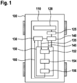
- Fig. 1 shows a schematic illustration of a vehicle 100 comprising a brake system 110 according to an embodiment of the present invention.
- the vehicle 100 is a utility vehicle or commercial vehicle, such as a truck.
- the brake system 110 comprises at least one brake chamber 120, an electronic pressure modulator 130, a solenoid valve 140 and a controller 150.
- the electronic pressure modulator 130 is configured to modulate pressure in the brake chamber 120.
- the electronic pressure modulator 130 is fluidically and/or communicatively connected to the solenoid valve 140.
- the solenoid valve 140 is associated with a relay valve 125 for the brake chamber 120. More specifically, the relay valve 125 is fluidically connected to the brake chamber 120. Furthermore, even though not shown in Fig. 1 , the relay valve 125 is connected into a fluid line between the brake chamber 120 and a reservoir for pressurized fluid.
- the controller 150 is communicatively connected at least to the electronic pressure modulator 130 and to the solenoid valve 140.
- the controller 150 is configured to control the brake system 110. To this end, the controller 150 comprises means or units configured to execute, control or perform steps of a method for controlling a brake system as described in Fig. 3 or a similar method. The controller 150 also comprises means or units configured to execute, control or perform steps of a method for determining a response time parameter of the brake chamber 120 as described in Fig. 2 or a similar method.
- the controller 150 comprises means 152 for detecting, means 154 for setting and means 156 for modulating.
- the controller 150 or the means for detecting 152 is configured to read or receive a pressure signal 135 from the electronic pressure modulator 130.
- the pressure signal 135 represents fluid pressure measured at the electronic pressure modulator.
- the controller 150 or the means for detecting 152 is configured to read or receive a pulse signal 145 from the solenoid valve 140.
- the pulse signal 145 represents information on a pulse of the solenoid valve 140.
- the information on the pulse of the solenoid valve 140 may comprise an opening time of the solenoid valve 140, a closing time of the solenoid valve 140 and/or a pulse duration or time interval between opening and closing of the solenoid valve 140.
- the means 152 for detecting is configured to detect an end of a fallback slope of the pressure signal 135 after a pulse of the solenoid valve 140. Furthermore, the means 152 for detecting is configured to pass on information the end of the fallback slope of the pressure signal 135 to the means 154 for setting.
- the means 154 for setting is configured to set the response time parameter of the brake chamber 120 depending on the detected end of the fallback slope.
- the means 154 for setting also is configured to pass on information on the set response time parameter to the means 156 for modulating.
- the means 156 for modulating is configured to modulate pressure for the brake chamber 120 depending on the response time parameter.
- the means 156 for modulating is configured to generate a control signal 160 depending on the response time parameter and output the control signal 160 to the electronic pressure modulator 130.
- the control signal 160 is suitable for driving the electronic pressure modulator 130 so as to modulate pressure for the brake chamber 120.
- the brake system 110 may also comprise a sensor for measuring the pressure signal 135 at the electronic pressure modulator 130, even though this is not explicitly shown in Fig. 1 .
- the controller 150 may be distinct from the brake system 110, for example realized as or in another controller of the vehicle 100.
- the controller 150 and the electronic pressure modulator 130 may be combined.
- the electronic pressure modulator and the solenoid valve 140 may be combined.
- the electronic pressure modulator 130 may then comprise a circuit board, at least one solenoid valve and electronics.
- Fig. 2 shows a flowchart of a method 200 for determining according to an embodiment of the present invention.
- the method 200 is executable for determining a response time parameter of a brake chamber of a brake system for a vehicle.
- the brake system corresponds to or is similar to the brake system as described with reference to Fig. 1 .
- the method 200 or the steps of the method 200 may be executed using the controller as described with reference to Fig. 1 or a similar controller.
- a step 210 of detecting an end of a fallback slope of a pressure signal as measured at the electronic pressure modulator is detected after a pulse of the solenoid valve.
- the end of the fallback slope is detected by searching for a change of sign in a slope or derivative of the pressure signal after the pulse of the solenoid valve in the step 210 of detecting.
- the response time parameter of the brake chamber is set depending on the detected end of the fallback slope.
- the method 200 for determining comprises a step 230 of computing a response time using a pulse duration of the solenoid valve and a fallback duration from the end of the pulse of the solenoid valve to the end of the fallback slope.
- the computed response time is set as the response time parameter in the step 220 of setting.
- a time constant used in brake chamber simulation is set as the response time parameter as a function of a pulse duration of the solenoid valve and a fallback duration from the end of the pulse of the solenoid valve to the end of the fallback slope.
- the method 200 for determining comprises a step 240 of comparing the pressure signal as measured at the electronic pressure modulator at the end of the fallback slope to a model pressure value of a brake pressure simulation at the end of the fallback slope, in order to obtain a pressure difference.
- a time constant used in the brake pressure simulation is adjusted depending on the pressure difference the step 220 of setting, in order to set the response time parameter.
- Fig. 3 shows a flowchart of a method 300 for controlling according to an embodiment of the present invention.
- the method 300 is executable for controlling a brake system for a vehicle.
- the brake system corresponds to or is similar to the brake system as described with reference to Fig. 1 .
- the method 300 or the steps of the method 300 may be executed using the controller as described with reference to Fig. 1 or a similar controller.
- the response time parameter of the brake chamber is determined by executing the method for determining as described with reference to Fig. 1 or a similar method.
- the step 305 of determining can be executed repeatedly, periodically or once.
- a step 350 of modulating pressure for the brake chamber is modulated depending on the response time parameter.
- Fig. 4 shows a schematic pressure diagram 400 according to an embodiment of the present invention.
- the time t is plotted on the abscissa in seconds
- the pressure P is plotted on the ordinate in bar.
- a first graph of the pressure diagram 400 represents the pressure signal 135 as described with reference to Fig. 1 .
- the pressure signal 135 shows a pressure gradient as measured at the electronic pressure modulator of the brake system as described with reference to Fig. 1 .
- a second graph of the pressure diagram 400 represents actual pressure 425 or simulated pressure 425 in the brake chamber of Fig. 1 or a similar brake chamber.
- the first time instant t 1 corresponds to an opening of the solenoid valve of the brake system as described with reference to Fig. 1 .
- the first time instant t 1 corresponds to a beginning of a pulse of the solenoid valve.
- the pressure signal 135 has a greater rising slope than the actual pressure 425.
- the second time instant t 2 corresponds to a closing of the solenoid valve of the pressure modulator of the brake system as described with reference to Fig. 1 .
- the second time instant t 2 corresponds to an end of the pulse of the solenoid valve.
- the second time instant t 2 marks a peak in the pressure signal 135.
- the pressure signal 135 has a falling slope
- the actual pressure 425 has a rising slope.
- the time interval between the second time instant t 2 and the third time instant t 3 corresponds to a fallback time t f of the pressure signal 135.
- the third time instant t 3 represents the end of a fallback slope of the pressure signal 135.
- the third time instant t 3 corresponds to a state in which a pressure value of the pressure signal 135 is equal to the actual pressure 425. From the third time instant t 3 onward, both the pressure signal 135 and the actual pressure 425 level off and have the same overlapping course again.
- Fig. 5 shows a schematic pressure diagram 500 according to an embodiment of the present invention.
- the pressure diagram 500 corresponds to the pressure diagram of Fig. 4 except that out of the time-related reference signs only the third time instant t 3 is indicated.
- the pressure diagram 500 relates to a brake chamber which is characterized as a large-sized chamber.
- Fig. 6 shows a schematic pressure diagram 600 according to an embodiment of the present invention.
- the pressure diagram 600 corresponds to the pressure diagram of Fig. 5 except that the pressure diagram 600 relates to a brake chamber which is characterized as a medium-sized chamber.
- the fallback time in Fig. 6 is shorter than in Fig. 4 or Fig. 5 .
- Fig. 7 shows a schematic pressure diagram 700 according to an embodiment of the present invention.
- the pressure diagram 700 corresponds to the pressure diagram of Fig. 5 or Fig. 6 except that the pressure diagram 700 relates to a brake chamber which is characterized as a small -sized chamber.
- the fallback time in Fig. 7 is shorter than in Fig. 6 .
- Each pulse of the solenoid valve 140 in the electronic pressure modulator 130 results in an overshoot-like behavior of the pressure signal 135, which is characterized by the system-level environment.
- the measured pressure or local pressure in the electronic pressure modulator 130 reaches its peak, as shown in the pressure signal 135, and then starts falling back because of a feedback orifice in a control piston.
- This fallback or fallback slope is characterized by a more or less constant pressure gradient, and lasts until the actual pressure in the brake chamber 120 catches up with the pressure signal 135.
- the end of the fallback slope is detected in the local pressure signal 135, and it gives a point in time when the actual brake pressure in the brake chamber 120 can be regarded as equal to the value of the pressure signal 135.
- the end of the fallback slope is used to set or update response-time parameters of the brake chamber 120.
- the aforementioned details accommodate an explicit method and an implicit method.
- the explicit method after each pulse of the solenoid valve, the end of the fallback slope is detected by searching for a change in gradient direction, in particular a zero-crossing in the pressure derivative of the pressure signal 135. Furthermore, the time duration recorded as the fallback time t f and the reaction or response time parameter of the brake chamber 120, (or example, a time constant of a PT1 used for brake chamber simulation, is updated as a function of the pulse duration and the fallback duration.
- the implicit method the end of the fallback slope also is detected after each pulse. Furthermore, there is a simulation of the actual brake pressure running in parallel. When the end-of-slope is detected, the actual brake pressure should be equal to the local or measured pressure as represented by pressure signal 135. If it is higher, or lower, the time-constant used for simulation is incremented or decremented accordingly.
Landscapes
- Engineering & Computer Science (AREA)
- Transportation (AREA)
- Mechanical Engineering (AREA)
- Regulating Braking Force (AREA)
- Braking Systems And Boosters (AREA)
Abstract
Description
- The present invention relates to a method for determining a response time parameter of a brake chamber of a brake system for a vehicle, to a method for controlling a brake system for a vehicle, to a controller and to a brake system for a vehicle.
- Brake pressure in a vehicle may have a characteristic response time or delay when reacting to pressure changes, and it may be controlled by an electronic pressure modulator (EPM). This response time may vary with brake chamber size and pipe diameter and length. Since it is desirable for this response time to be known, it may be estimated based on parametric simulations, or it may be considered as a fixed value during development. Conventionally, the response time of a brake chamber may not be known, and it may vary from vehicle to vehicle. Actual brake pressure, in a dynamic sense, may also not be known conventionally.
- Against this background, it is the object of the present invention to provide an improved method for determining a response time parameter of a brake chamber of a brake system for a vehicle, an improved method for controlling a brake system for a vehicle, an improved controller and an improved brake system for a vehicle.
- This object is achieved by a method for determining a response time parameter of a brake chamber of a brake system for a vehicle, by a method for controlling a brake system for a vehicle, by a controller and by a brake system for a vehicle according to the main claims.
- According to embodiments, for example, brake chamber dynamics data may be determined by observing relay valve pressure. In particular, a brake chamber response time or delay may be determined by observing pressure gradients in a pressure signal of an electronic pressure modulator of a vehicle brake system. Herein, a defined relationship between a course or gradient of the pressure signal as measured at the electronic pressure modulator and an actual pressure in the brake chamber may be utilized.
- Advantageously, according to embodiments, knowledge of brake chamber response time helps pressure control adaptation in order to guarantee control loop response time with regards to brake pressure. Furthermore, knowledge of brake chamber dynamics, particularly brake chamber response time, helps ABS performance, with the potential to decrease brake distance, because knowledge of actual brake pressure peaks can help ABS better detect slip-threshold pressure. It may otherwise not be possible to measure and tune this parameter without external sensors on the brake chamber, but according to embodiments it may be a self-configuration feature, or it may work like continuous online learning. Thus, pressure control performance may be ensured with regard to brake chamber pressure, not local pressure of the electronic pressure modulator, without external tuning. Therefore, according to embodiments, improvements in brake control, ABS and pressure control may be provided for a vehicle.
- Also, tedious procedures for finding appropriate tuning or simulations for brake chamber dynamics can be avoided, without simply leaving the parameter constant for all types of vehicles and brake systems. For example, this also makes ABS behavior more predictable and reproducible. Moreover, an electronic pressure modulator, which may be sensitive to brake chamber size, may be operated reliably to provide safe braking functions, and variability of pressure control performance may be minimized or eliminated. Pressure control may be made more robust with regard to output parameters, such as brake chamber size, tubing the like. In order to make pressure control robust and to ensure pressure control performance, brake chamber parameters may be identified according to embodiments.
- A method for determining a response time parameter of a brake chamber of a brake system for a vehicle, wherein the brake system comprises an electronic pressure modulator configured to modulate pressure in the brake chamber and a solenoid valve for the brake chamber, comprises:
- detecting an end of a fallback slope of a pressure signal as measured at the electronic pressure modulator after a pulse of the solenoid valve; and
- setting the response time parameter of the brake chamber depending on the detected end of the fallback slope.
- The vehicle may be a utility vehicle or commercial vehicle, for example a truck, bus or the like. The method or the steps of the method may be executed using a controller. The solenoid valve may be part of or combined with the electronic pressure modulator. The electronic pressure modulator may comprise the solenoid valve. The end of the fallback slope may correspond to a state in which pressure represented by the pressure signal as measured at the electronic pressure modulator and actual brake chamber pressure are equal. At the end of the fallback slope the pressure signal as measured at the electronic pressure modulator may show a constant or near-constant pressure gradient, or it may revert direction due to noise or disturbances. In the step of setting, the response time parameter may be updated. Additionally or alternatively, in the step of setting, the response time parameter may be maintained or changed. The brake system may also comprise a sensor for measuring the pressure signal at the electronic pressure modulator. The brake system may further comprise a relay valve. The relay valve may function as a pneumatic amplification mechanism. The relay valve may be a mechanism that controls pressure and air-flow output, and is controlled by pressure input. The solenoid valve may drive the relay valve. The relay valve may have a feedback orifice. The feedback orifice may be an opening connecting control and output chambers of the relay valve. The relay valve may have a piston inside. When the solenoid valve is open, the piston may keep opening more and more. When the solenoid valve closes, there may be the pressure peak, and the piston may start closing again. The piston of the relay valve may close at the end of the fallback slope, later than the solenoid valve. The electro-pneumatic modulator may be defined as an electronically controlled relay valve. Control pressure of the relay valve may not be an external input, but instead the control pressure may be created by solenoid valves. An output of the relay valve may be measured by means of a sensor, and a feedback loop may be created, wherein the solenoid valves may keep increasing or decreasing control pressure until a pre-defined output pressure is achieved. A pulse of the solenoid valve may be a time interval or duration between opening and closing of the solenoid valve that provides the input to the relay. An end of the pulse of the solenoid valve may correspond to a peak in the pressure signal as measured at the electronic pressure modulator.
- According to an embodiment, in the step of detecting the end of the fallback slope may be detected by searching for a change of sign in a slope or derivative of the pressure signal after the pulse of the solenoid valve. The change of sign may include a positive sign, a negative sign and zero. Such an embodiment offers the advantage that the end of the fallback slope can be identified in a reliable and effective way.
- Also, according to an embodiment, the method may comprise a step of computing a response time using a pulse duration of the solenoid valve and a fallback duration from the end of the pulse of the solenoid valve to the end of the fallback slope. In the step of setting the response time may be set as the response time parameter. Such an embodiment offers the advantage that meaningful dynamic properties of the brake chamber can be determined in an easy and reliable manner.
- Furthermore, according to an embodiment, in the step of setting a time constant used in brake chamber simulation may be set as the response time parameter as a function of a pulse duration of the solenoid valve and a fallback duration from the end of the pulse of the solenoid valve to the end of the fallback slope. Such an embodiment offers the advantage that simulations of brake chamber dynamics and other properties can be made more accurate.
- According to an embodiment, the method may comprise a step of comparing the pressure signal as measured at the electronic pressure modulator at the end of the fallback slope to a model pressure value of a brake pressure simulation at the end of the fallback slope, in order to obtain a pressure difference. The pressure difference may indicate that the pressure signal and the model pressure value are equal or different at the end of the fallback slope. Such an embodiment offers the advantage that the detected end of the fallback slope can be used as a meaningful point in time for a comparison between measured values and model values, giving rise to a simple and quick test of the model or simulations.
- In this context, according to an embodiment, in the step of setting a time constant used in the brake pressure simulation may be adjusted depending on the pressure difference, in order to set the response time parameter. When being adjusted, the time constant may be incremented, decremented or maintained at the previous level or value. Such an embodiment offers the advantage that the brake pressure simulation can be enhanced in an easy and reliable manner by updates in case of a pressure difference obtained in the step of comparing.
- A method for controlling a brake system for a vehicle, wherein the brake system comprises a brake chamber, an electronic pressure modulator configured to modulate pressure in the brake chamber and a solenoid valve for the brake chamber, comprises:
- determining the response time parameter of the brake chamber pursuant to an embodiment of the aforementioned method; and
- modulating pressure for the brake chamber depending on the response time parameter.
- The method or the steps of the method may be executed using a controller. Thus, the method may be executed to control an embodiment of a subsequently mentioned brake system.
- The approach presented here also provides a controller configured to execute, control or perform, in corresponding units, the steps of a variant of a method presented here. The object underlying the invention may be achieved quickly and efficiently also by this embodiment of the invention in form of a controller.
- To this end, the controller may comprise at least one processing unit for processing signals or data, at least one storage unit for storing signals or data, at least one interface to the sensor or an actuator reading sensor signals from the sensor or for outputting control signals to the actuator and/or at least one communication interface for reading or outputting data embedded in a communication protocol. The processing unit may, for example, be a signal processor, a microcontroller or the like, wherein the storage unit may be a flash memory, an EPROM, EEPROM or a magnetic storage unit. The communication interface may be configured to read or output data in a wireless and/or wired manner, wherein a communication interface capable of reading or outputting data via a line may read this data electrically or optically from a corresponding data transmission line or output the same into a corresponding data transmission line, for example.
- A controller may be a technical device processing sensor signals and outputting control and/or data signals depending thereon. The controller may comprise an interface, which may be configured as hardware and/or software. If configured as hardware, the interfaces may, for example, be part of a so-called system ASIC including various functions of the controller. However, it is also possible for the interfaces to be discrete integrated circuits or at least partly consist of discrete components. If configured as software, the interfaces may be software modules present on a microcontroller along with other software modules, for example.
- What is also advantageous is a computer program product or to program with program code which may be stored on a machine-readable carrier or storage medium, such as a semiconductor memory, a hard-drive memory or an optical memory, and is used for executing, performing/controlling the steps of the method according to one of the embodiments previously described, in particular when the program product or program is executed on a computer or a device.
- A brake system for a vehicle comprises:
- a brake chamber;
- an electronic pressure modulator configured to modulate pressure in the brake chamber;
- a solenoid valve for the brake chamber; and
- a controller configured to execute, control or perform, in corresponding units, the steps of an embodiment of the aforementioned method for controlling, wherein the controller is communicatively connected to the electronic pressure modulator and to the solenoid valve.
- The brake system may comprise an embodiment of the aforementioned controller or a similar controller. The solenoid valve may be part of or combined with the electronic pressure modulator.
- Embodiments of the approach presented here shall be explained in greater detail in the subsequent description with reference to the figures, wherein:
-
Fig. 1 shows a schematic illustration of a vehicle comprising a brake system according to an embodiment of the present invention; -
Fig. 2 shows a flowchart of a method for determining according to an embodiment of the present invention; -
Fig. 3 shows a flowchart of a method for controlling according to an embodiment of the present invention; -
Fig. 4 shows a schematic pressure diagram according to an embodiment of the present invention; -
Fig. 5 shows a schematic pressure diagram according to an embodiment of the present invention; -
Fig. 6 shows a schematic pressure diagram according to an embodiment of the present invention; and -
Fig. 7 shows a schematic pressure diagram according to an embodiment of the present invention. - In the following description of advantageous embodiments of the present invention, the same or similar reference numerals shall be used for the elements depicted in the various figures and acting in a similar way, wherein repeated description of these elements shall be omitted.
-
Fig. 1 shows a schematic illustration of avehicle 100 comprising abrake system 110 according to an embodiment of the present invention. Thevehicle 100 is a utility vehicle or commercial vehicle, such as a truck. Thebrake system 110 comprises at least onebrake chamber 120, anelectronic pressure modulator 130, asolenoid valve 140 and a controller 150. - The
electronic pressure modulator 130 is configured to modulate pressure in thebrake chamber 120. Theelectronic pressure modulator 130 is fluidically and/or communicatively connected to thesolenoid valve 140. Thesolenoid valve 140 is associated with arelay valve 125 for thebrake chamber 120. More specifically, therelay valve 125 is fluidically connected to thebrake chamber 120. Furthermore, even though not shown inFig. 1 , therelay valve 125 is connected into a fluid line between thebrake chamber 120 and a reservoir for pressurized fluid. The controller 150 is communicatively connected at least to theelectronic pressure modulator 130 and to thesolenoid valve 140. - The controller 150 is configured to control the
brake system 110. To this end, the controller 150 comprises means or units configured to execute, control or perform steps of a method for controlling a brake system as described inFig. 3 or a similar method. The controller 150 also comprises means or units configured to execute, control or perform steps of a method for determining a response time parameter of thebrake chamber 120 as described inFig. 2 or a similar method. - According to the embodiment shown here, the controller 150 comprises
means 152 for detecting, means 154 for setting and means 156 for modulating. The controller 150 or the means for detecting 152 is configured to read or receive apressure signal 135 from theelectronic pressure modulator 130. Thepressure signal 135 represents fluid pressure measured at the electronic pressure modulator. Furthermore, the controller 150 or the means for detecting 152 is configured to read or receive apulse signal 145 from thesolenoid valve 140. Thepulse signal 145 represents information on a pulse of thesolenoid valve 140. The information on the pulse of thesolenoid valve 140 may comprise an opening time of thesolenoid valve 140, a closing time of thesolenoid valve 140 and/or a pulse duration or time interval between opening and closing of thesolenoid valve 140. - The means 152 for detecting is configured to detect an end of a fallback slope of the
pressure signal 135 after a pulse of thesolenoid valve 140. Furthermore, themeans 152 for detecting is configured to pass on information the end of the fallback slope of thepressure signal 135 to themeans 154 for setting. The means 154 for setting is configured to set the response time parameter of thebrake chamber 120 depending on the detected end of the fallback slope. The means 154 for setting also is configured to pass on information on the set response time parameter to themeans 156 for modulating. The means 156 for modulating is configured to modulate pressure for thebrake chamber 120 depending on the response time parameter. To this end, themeans 156 for modulating is configured to generate acontrol signal 160 depending on the response time parameter and output thecontrol signal 160 to theelectronic pressure modulator 130. Thecontrol signal 160 is suitable for driving theelectronic pressure modulator 130 so as to modulate pressure for thebrake chamber 120. - The
brake system 110 may also comprise a sensor for measuring thepressure signal 135 at theelectronic pressure modulator 130, even though this is not explicitly shown inFig. 1 . According to an embodiment, the controller 150 may be distinct from thebrake system 110, for example realized as or in another controller of thevehicle 100. According to another embodiment, the controller 150 and theelectronic pressure modulator 130 may be combined. According to yet another embodiment, the electronic pressure modulator and thesolenoid valve 140 may be combined. Theelectronic pressure modulator 130 may then comprise a circuit board, at least one solenoid valve and electronics. -
Fig. 2 shows a flowchart of amethod 200 for determining according to an embodiment of the present invention. Themethod 200 is executable for determining a response time parameter of a brake chamber of a brake system for a vehicle. The brake system corresponds to or is similar to the brake system as described with reference toFig. 1 . Themethod 200 or the steps of themethod 200 may be executed using the controller as described with reference toFig. 1 or a similar controller. - In a
step 210 of detecting, an end of a fallback slope of a pressure signal as measured at the electronic pressure modulator is detected after a pulse of the solenoid valve. In particular, the end of the fallback slope is detected by searching for a change of sign in a slope or derivative of the pressure signal after the pulse of the solenoid valve in thestep 210 of detecting. Subsequently, in astep 220 of setting, the response time parameter of the brake chamber is set depending on the detected end of the fallback slope. - According to an embodiment, the
method 200 for determining comprises astep 230 of computing a response time using a pulse duration of the solenoid valve and a fallback duration from the end of the pulse of the solenoid valve to the end of the fallback slope. Herein, the computed response time is set as the response time parameter in thestep 220 of setting. - According to a further embodiment, in the
step 220 setting, a time constant used in brake chamber simulation is set as the response time parameter as a function of a pulse duration of the solenoid valve and a fallback duration from the end of the pulse of the solenoid valve to the end of the fallback slope. - Alternatively or additionally, the
method 200 for determining comprises astep 240 of comparing the pressure signal as measured at the electronic pressure modulator at the end of the fallback slope to a model pressure value of a brake pressure simulation at the end of the fallback slope, in order to obtain a pressure difference. Herein, a time constant used in the brake pressure simulation is adjusted depending on the pressure difference thestep 220 of setting, in order to set the response time parameter. -
Fig. 3 shows a flowchart of amethod 300 for controlling according to an embodiment of the present invention. Themethod 300 is executable for controlling a brake system for a vehicle. The brake system corresponds to or is similar to the brake system as described with reference toFig. 1 . Themethod 300 or the steps of themethod 300 may be executed using the controller as described with reference toFig. 1 or a similar controller. - In a
step 305 of determining, the response time parameter of the brake chamber is determined by executing the method for determining as described with reference toFig. 1 or a similar method. Thestep 305 of determining can be executed repeatedly, periodically or once. Subsequently, in astep 350 of modulating, pressure for the brake chamber is modulated depending on the response time parameter. -
Fig. 4 shows a schematic pressure diagram 400 according to an embodiment of the present invention. In the pressure diagram 400, the time t is plotted on the abscissa in seconds, and the pressure P is plotted on the ordinate in bar. A first graph of the pressure diagram 400 represents thepressure signal 135 as described with reference toFig. 1 . Thepressure signal 135 shows a pressure gradient as measured at the electronic pressure modulator of the brake system as described with reference toFig. 1 . A second graph of the pressure diagram 400 representsactual pressure 425 orsimulated pressure 425 in the brake chamber ofFig. 1 or a similar brake chamber. - To a first time instant t1, the
pressure signal 135 and theactual pressure 425 have the same course and thus overlap. The first time instant t1 corresponds to an opening of the solenoid valve of the brake system as described with reference toFig. 1 . In other words, the first time instant t1 corresponds to a beginning of a pulse of the solenoid valve. Between the first time instant t1 and a second time instant t2, thepressure signal 135 has a greater rising slope than theactual pressure 425. The second time instant t2 corresponds to a closing of the solenoid valve of the pressure modulator of the brake system as described with reference toFig. 1 . In other words, the second time instant t2 corresponds to an end of the pulse of the solenoid valve. The second time instant t2 marks a peak in thepressure signal 135. Between the second time instant t2 and a third second time instant t3, thepressure signal 135 has a falling slope, and theactual pressure 425 has a rising slope. The time interval between the second time instant t2 and the third time instant t3, corresponds to a fallback time tf of thepressure signal 135. The third time instant t3 represents the end of a fallback slope of thepressure signal 135. In particular, the third time instant t3 corresponds to a state in which a pressure value of thepressure signal 135 is equal to theactual pressure 425. From the third time instant t3 onward, both thepressure signal 135 and theactual pressure 425 level off and have the same overlapping course again. -
Fig. 5 shows a schematic pressure diagram 500 according to an embodiment of the present invention. The pressure diagram 500 corresponds to the pressure diagram ofFig. 4 except that out of the time-related reference signs only the third time instant t3 is indicated. The pressure diagram 500 relates to a brake chamber which is characterized as a large-sized chamber. -
Fig. 6 shows a schematic pressure diagram 600 according to an embodiment of the present invention. The pressure diagram 600 corresponds to the pressure diagram ofFig. 5 except that the pressure diagram 600 relates to a brake chamber which is characterized as a medium-sized chamber. The fallback time inFig. 6 is shorter than inFig. 4 or Fig. 5 . -
Fig. 7 shows a schematic pressure diagram 700 according to an embodiment of the present invention. The pressure diagram 700 corresponds to the pressure diagram ofFig. 5 orFig. 6 except that the pressure diagram 700 relates to a brake chamber which is characterized as a small -sized chamber. The fallback time inFig. 7 is shorter than inFig. 6 . - With reference to the figures previously described, embodiments of the present invention shall be summarized and/or briefly presented in other words in the following.
- Each pulse of the
solenoid valve 140 in theelectronic pressure modulator 130 results in an overshoot-like behavior of thepressure signal 135, which is characterized by the system-level environment. At the end of the pulse of thesolenoid valve 140, the measured pressure or local pressure in theelectronic pressure modulator 130 reaches its peak, as shown in thepressure signal 135, and then starts falling back because of a feedback orifice in a control piston. This fallback or fallback slope is characterized by a more or less constant pressure gradient, and lasts until the actual pressure in thebrake chamber 120 catches up with thepressure signal 135. The end of the fallback slope is detected in thelocal pressure signal 135, and it gives a point in time when the actual brake pressure in thebrake chamber 120 can be regarded as equal to the value of thepressure signal 135. The end of the fallback slope is used to set or update response-time parameters of thebrake chamber 120. - The aforementioned details accommodate an explicit method and an implicit method. In the explicit method, after each pulse of the solenoid valve, the end of the fallback slope is detected by searching for a change in gradient direction, in particular a zero-crossing in the pressure derivative of the
pressure signal 135. Furthermore, the time duration recorded as the fallback time tf and the reaction or response time parameter of thebrake chamber 120, (or example, a time constant of a PT1 used for brake chamber simulation, is updated as a function of the pulse duration and the fallback duration. In the implicit method, the end of the fallback slope also is detected after each pulse. Furthermore, there is a simulation of the actual brake pressure running in parallel. When the end-of-slope is detected, the actual brake pressure should be equal to the local or measured pressure as represented bypressure signal 135. If it is higher, or lower, the time-constant used for simulation is incremented or decremented accordingly. -
- 100
- vehicle
- 110
- brake system
- 120
- brake chamber
- 125
- relay valve
- 130
- electronic pressure modulator
- 135
- pressure signal
- 140
- solenoid valve
- 145
- pulse signal
- 150
- controller
- 152
- means for detecting
- 154
- means for setting
- 156
- means for modulating
- 160
- control signal
- 200
- method for determining
- 210
- step of detecting
- 220
- step of setting
- 230
- step of computing
- 240
- step of comparing
- 300
- method for controlling
- 305
- step of determining
- 350
- step of modulating
- 400
- pressure diagram
- P
- pressure
- t
- time
- t1
- first time instant
- t2
- second time instant
- t3
- third time instant
- tf
- fallback time
- 425
- pressure in the brake chamber
- 500
- pressure diagram
- 600
- pressure diagram
- 700
- pressure diagram
Claims (9)
- Method (200) for determining a response time parameter of a brake chamber (120) of a brake system (110) for a vehicle (100), wherein the brake system (110) comprises an electronic pressure modulator (130) configured to modulate pressure in the brake chamber (120) and a solenoid valve (140) for the brake chamber (120), wherein the method (200) comprises:detecting (210) an end (t3) of a fallback slope of a pressure signal (135) as measured at the electronic pressure modulator (130) after a pulse of the solenoid valve (140); andsetting (220) the response time parameter of the brake chamber (120) depending on the detected end (t3) of the fallback slope.
- Method (200) according to claim 1, wherein in the step (210) of detecting the end (t3) of the fallback slope is detected by searching for a change of sign in a slope or derivative of the pressure signal (135) after the pulse of the solenoid valve (140).
- Method (200) according to one of the preceding claims, comprising a step (230) of computing a response time using a pulse duration (t2-t1) of the solenoid valve (120) and a fallback duration (tf) from the end (t2) of the pulse of the solenoid valve (140) to the end (t3) of the fallback slope, wherein in the step (220) of setting the response time is set as the response time parameter.
- Method (200) according to one of the preceding claims, wherein in the step (220) of setting a time constant used in brake chamber simulation is set as the response time parameter as a function of a pulse duration (t2-t1) of the solenoid valve (140) and a fallback duration (tf) from the end (t2) of the pulse of the solenoid valve (140) to the end (t3) of the fallback slope.
- Method (200) according to one of the preceding claims, comprising a step (240) of comparing the pressure signal (135) as measured at the electronic pressure modulator (130) at the end (t3) of the fallback slope to a model pressure value of a brake pressure simulation at the end (t3) of the fallback slope, in order to obtain a pressure difference.
- Method (200) according to claim 5, wherein in the step (220) of setting a time constant used in the brake pressure simulation is adjusted depending on the pressure difference, in order to set the response time parameter.
- Method (300) for controlling a brake system (110) for a vehicle (100), wherein the brake system (110) comprises a brake chamber (120), an electronic pressure modulator (130) configured to modulate pressure in the brake chamber (120) and a solenoid valve (140) for the brake chamber (120), wherein the method (300) comprises:determining (305) the response time parameter of the brake chamber (120) pursuant to the method (200) according to one of the preceding claims; andmodulating (350) pressure for the brake chamber (120) depending on the response time parameter.
- Controller (150) configured to to execute, control or perform, in corresponding units (152, 154, 158), the steps of a method (200; 300) according to one of the preceding claims.
- Brake system (110) for a vehicle (100), wherein the brake system (110) comprises:a brake chamber (120);an electronic pressure modulator (130) configured to modulate pressure in the brake chamber (120);a solenoid valve (140) for the brake chamber (120); anda controller (150) configured to execute, control or perform, in corresponding units (152, 154, 158), the steps of the method (300) according to claim 7, wherein the controller (150) is communicatively connected to the electronic pressure modulator (130) and to the solenoid valve (140).
Priority Applications (2)
| Application Number | Priority Date | Filing Date | Title |
|---|---|---|---|
| EP18210064.4A EP3663150B1 (en) | 2018-12-04 | 2018-12-04 | Method for determining a response time parameter of a brake chamber of a brake system for a vehicle, method for controlling a brake system for a vehicle and brake system for a vehicle |
| PCT/EP2019/082437 WO2020114823A1 (en) | 2018-12-04 | 2019-11-25 | Method for determining a response time parameter of a brake chamber of a brake system for a vehicle, method for controlling a brake system for a vehicle and brake system for a vehicle |
Applications Claiming Priority (1)
| Application Number | Priority Date | Filing Date | Title |
|---|---|---|---|
| EP18210064.4A EP3663150B1 (en) | 2018-12-04 | 2018-12-04 | Method for determining a response time parameter of a brake chamber of a brake system for a vehicle, method for controlling a brake system for a vehicle and brake system for a vehicle |
Publications (2)
| Publication Number | Publication Date |
|---|---|
| EP3663150A1 true EP3663150A1 (en) | 2020-06-10 |
| EP3663150B1 EP3663150B1 (en) | 2023-02-08 |
Family
ID=64604526
Family Applications (1)
| Application Number | Title | Priority Date | Filing Date |
|---|---|---|---|
| EP18210064.4A Active EP3663150B1 (en) | 2018-12-04 | 2018-12-04 | Method for determining a response time parameter of a brake chamber of a brake system for a vehicle, method for controlling a brake system for a vehicle and brake system for a vehicle |
Country Status (2)
| Country | Link |
|---|---|
| EP (1) | EP3663150B1 (en) |
| WO (1) | WO2020114823A1 (en) |
Cited By (2)
| Publication number | Priority date | Publication date | Assignee | Title |
|---|---|---|---|---|
| CN113135173A (en) * | 2021-05-24 | 2021-07-20 | 湖南三一车身有限公司 | Braking difference monitoring system based on air braking response time |
| CN113688584A (en) * | 2020-12-05 | 2021-11-23 | 清华大学 | Method for estimating pressure of brake chamber of vehicle air pressure line control brake system |
Citations (2)
| Publication number | Priority date | Publication date | Assignee | Title |
|---|---|---|---|---|
| EP0733531A2 (en) * | 1995-03-24 | 1996-09-25 | WABCO GmbH | Method for braking a vehicle |
| US5788337A (en) * | 1993-04-16 | 1998-08-04 | Itt Automotive Europe Gmbh | Auxiliary energy brake system of automotive vehicles |
-
2018
- 2018-12-04 EP EP18210064.4A patent/EP3663150B1/en active Active
-
2019
- 2019-11-25 WO PCT/EP2019/082437 patent/WO2020114823A1/en not_active Ceased
Patent Citations (2)
| Publication number | Priority date | Publication date | Assignee | Title |
|---|---|---|---|---|
| US5788337A (en) * | 1993-04-16 | 1998-08-04 | Itt Automotive Europe Gmbh | Auxiliary energy brake system of automotive vehicles |
| EP0733531A2 (en) * | 1995-03-24 | 1996-09-25 | WABCO GmbH | Method for braking a vehicle |
Cited By (2)
| Publication number | Priority date | Publication date | Assignee | Title |
|---|---|---|---|---|
| CN113688584A (en) * | 2020-12-05 | 2021-11-23 | 清华大学 | Method for estimating pressure of brake chamber of vehicle air pressure line control brake system |
| CN113135173A (en) * | 2021-05-24 | 2021-07-20 | 湖南三一车身有限公司 | Braking difference monitoring system based on air braking response time |
Also Published As
| Publication number | Publication date |
|---|---|
| WO2020114823A1 (en) | 2020-06-11 |
| EP3663150B1 (en) | 2023-02-08 |
Similar Documents
| Publication | Publication Date | Title |
|---|---|---|
| EP3663150B1 (en) | Method for determining a response time parameter of a brake chamber of a brake system for a vehicle, method for controlling a brake system for a vehicle and brake system for a vehicle | |
| US11084468B2 (en) | Device and method for actuating valves | |
| Li et al. | Angular acceleration estimation-based incremental nonlinear dynamic inversion for robust flight control | |
| US20060052959A1 (en) | Mathematical model useful for determining and calibrating output of a linear sensor | |
| US9205819B2 (en) | Electronic control device for a braking system, suitable for a distance control system | |
| US7865327B2 (en) | Method for determining the temperature of an electrical component with the aid of a temperature model | |
| US9988025B2 (en) | Method for ascertaining a pressure-volume characteristic of a braking system of a vehicle, and evaluation and/or control apparatus for at least one braking system component of a braking system of a vehicle | |
| CN110753979A (en) | Method and device for actuating a component movable by means of a coil and a solenoid valve | |
| CN108625923B (en) | Apparatus and method for fast position control of a hydraulic actuator | |
| KR102729857B1 (en) | System of modeling abs controller of vehicle | |
| CN101372222B (en) | Method and system for consistent braking control | |
| JP2016521658A (en) | Method for determining brake master cylinder estimated internal pressure and apparatus for determining brake master cylinder estimated internal pressure | |
| US6907373B2 (en) | Method for calibrating a sensor and switching arrangement for operating a sensor | |
| JP2012091577A (en) | Control device of linear solenoid valve | |
| US6668634B1 (en) | Method and device for estimating an admission pressure in a motor vehicle brake system | |
| CN1957230B (en) | Error correction method for displacement sensor signal | |
| CN114962631A (en) | Retarder electromagnetic valve control method, device, equipment and medium | |
| CN111479730B (en) | Braking system with correction device for valve opening time and method for correcting valve opening time | |
| CN103260980A (en) | Method for calibrating modulation point of pneumatic brake booster which is calculated on the basis of pressure sensor signal | |
| EP3879358B1 (en) | Generalized hysteresis control | |
| US10056832B2 (en) | Load driving control apparatus | |
| US4161962A (en) | Circuit for determining the response current of magnetic valves | |
| US7323858B2 (en) | Method for measuring pressure | |
| CN113715794B (en) | Method and system for intelligent braking of automobiles based on artificial intelligence | |
| CN113439047A (en) | Method and system for controlling the pneumatic pressure in a volume |
Legal Events
| Date | Code | Title | Description |
|---|---|---|---|
| PUAI | Public reference made under article 153(3) epc to a published international application that has entered the european phase |
Free format text: ORIGINAL CODE: 0009012 |
|
| STAA | Information on the status of an ep patent application or granted ep patent |
Free format text: STATUS: THE APPLICATION HAS BEEN PUBLISHED |
|
| AK | Designated contracting states |
Kind code of ref document: A1 Designated state(s): AL AT BE BG CH CY CZ DE DK EE ES FI FR GB GR HR HU IE IS IT LI LT LU LV MC MK MT NL NO PL PT RO RS SE SI SK SM TR |
|
| AX | Request for extension of the european patent |
Extension state: BA ME |
|
| STAA | Information on the status of an ep patent application or granted ep patent |
Free format text: STATUS: REQUEST FOR EXAMINATION WAS MADE |
|
| 17P | Request for examination filed |
Effective date: 20201210 |
|
| RBV | Designated contracting states (corrected) |
Designated state(s): AL AT BE BG CH CY CZ DE DK EE ES FI FR GB GR HR HU IE IS IT LI LT LU LV MC MK MT NL NO PL PT RO RS SE SI SK SM TR |
|
| GRAP | Despatch of communication of intention to grant a patent |
Free format text: ORIGINAL CODE: EPIDOSNIGR1 |
|
| STAA | Information on the status of an ep patent application or granted ep patent |
Free format text: STATUS: GRANT OF PATENT IS INTENDED |
|
| INTG | Intention to grant announced |
Effective date: 20220712 |
|
| GRAS | Grant fee paid |
Free format text: ORIGINAL CODE: EPIDOSNIGR3 |
|
| GRAA | (expected) grant |
Free format text: ORIGINAL CODE: 0009210 |
|
| STAA | Information on the status of an ep patent application or granted ep patent |
Free format text: STATUS: THE PATENT HAS BEEN GRANTED |
|
| AK | Designated contracting states |
Kind code of ref document: B1 Designated state(s): AL AT BE BG CH CY CZ DE DK EE ES FI FR GB GR HR HU IE IS IT LI LT LU LV MC MK MT NL NO PL PT RO RS SE SI SK SM TR |
|
| REG | Reference to a national code |
Ref country code: GB Ref legal event code: FG4D |
|
| REG | Reference to a national code |
Ref country code: CH Ref legal event code: EP Ref country code: AT Ref legal event code: REF Ref document number: 1547409 Country of ref document: AT Kind code of ref document: T Effective date: 20230215 |
|
| REG | Reference to a national code |
Ref country code: IE Ref legal event code: FG4D |
|
| REG | Reference to a national code |
Ref country code: DE Ref legal event code: R096 Ref document number: 602018045986 Country of ref document: DE |
|
| REG | Reference to a national code |
Ref country code: SE Ref legal event code: TRGR |
|
| REG | Reference to a national code |
Ref country code: LT Ref legal event code: MG9D |
|
| P01 | Opt-out of the competence of the unified patent court (upc) registered |
Effective date: 20230508 |
|
| REG | Reference to a national code |
Ref country code: NL Ref legal event code: MP Effective date: 20230208 |
|
| REG | Reference to a national code |
Ref country code: AT Ref legal event code: MK05 Ref document number: 1547409 Country of ref document: AT Kind code of ref document: T Effective date: 20230208 |
|
| PG25 | Lapsed in a contracting state [announced via postgrant information from national office to epo] |
Ref country code: RS Free format text: LAPSE BECAUSE OF FAILURE TO SUBMIT A TRANSLATION OF THE DESCRIPTION OR TO PAY THE FEE WITHIN THE PRESCRIBED TIME-LIMIT Effective date: 20230208 Ref country code: PT Free format text: LAPSE BECAUSE OF FAILURE TO SUBMIT A TRANSLATION OF THE DESCRIPTION OR TO PAY THE FEE WITHIN THE PRESCRIBED TIME-LIMIT Effective date: 20230609 Ref country code: NO Free format text: LAPSE BECAUSE OF FAILURE TO SUBMIT A TRANSLATION OF THE DESCRIPTION OR TO PAY THE FEE WITHIN THE PRESCRIBED TIME-LIMIT Effective date: 20230508 Ref country code: NL Free format text: LAPSE BECAUSE OF FAILURE TO SUBMIT A TRANSLATION OF THE DESCRIPTION OR TO PAY THE FEE WITHIN THE PRESCRIBED TIME-LIMIT Effective date: 20230208 Ref country code: LV Free format text: LAPSE BECAUSE OF FAILURE TO SUBMIT A TRANSLATION OF THE DESCRIPTION OR TO PAY THE FEE WITHIN THE PRESCRIBED TIME-LIMIT Effective date: 20230208 Ref country code: LT Free format text: LAPSE BECAUSE OF FAILURE TO SUBMIT A TRANSLATION OF THE DESCRIPTION OR TO PAY THE FEE WITHIN THE PRESCRIBED TIME-LIMIT Effective date: 20230208 Ref country code: HR Free format text: LAPSE BECAUSE OF FAILURE TO SUBMIT A TRANSLATION OF THE DESCRIPTION OR TO PAY THE FEE WITHIN THE PRESCRIBED TIME-LIMIT Effective date: 20230208 Ref country code: ES Free format text: LAPSE BECAUSE OF FAILURE TO SUBMIT A TRANSLATION OF THE DESCRIPTION OR TO PAY THE FEE WITHIN THE PRESCRIBED TIME-LIMIT Effective date: 20230208 Ref country code: AT Free format text: LAPSE BECAUSE OF FAILURE TO SUBMIT A TRANSLATION OF THE DESCRIPTION OR TO PAY THE FEE WITHIN THE PRESCRIBED TIME-LIMIT Effective date: 20230208 |
|
| PG25 | Lapsed in a contracting state [announced via postgrant information from national office to epo] |
Ref country code: PL Free format text: LAPSE BECAUSE OF FAILURE TO SUBMIT A TRANSLATION OF THE DESCRIPTION OR TO PAY THE FEE WITHIN THE PRESCRIBED TIME-LIMIT Effective date: 20230208 Ref country code: IS Free format text: LAPSE BECAUSE OF FAILURE TO SUBMIT A TRANSLATION OF THE DESCRIPTION OR TO PAY THE FEE WITHIN THE PRESCRIBED TIME-LIMIT Effective date: 20230608 Ref country code: GR Free format text: LAPSE BECAUSE OF FAILURE TO SUBMIT A TRANSLATION OF THE DESCRIPTION OR TO PAY THE FEE WITHIN THE PRESCRIBED TIME-LIMIT Effective date: 20230509 Ref country code: FI Free format text: LAPSE BECAUSE OF FAILURE TO SUBMIT A TRANSLATION OF THE DESCRIPTION OR TO PAY THE FEE WITHIN THE PRESCRIBED TIME-LIMIT Effective date: 20230208 |
|
| PG25 | Lapsed in a contracting state [announced via postgrant information from national office to epo] |
Ref country code: SM Free format text: LAPSE BECAUSE OF FAILURE TO SUBMIT A TRANSLATION OF THE DESCRIPTION OR TO PAY THE FEE WITHIN THE PRESCRIBED TIME-LIMIT Effective date: 20230208 Ref country code: RO Free format text: LAPSE BECAUSE OF FAILURE TO SUBMIT A TRANSLATION OF THE DESCRIPTION OR TO PAY THE FEE WITHIN THE PRESCRIBED TIME-LIMIT Effective date: 20230208 Ref country code: EE Free format text: LAPSE BECAUSE OF FAILURE TO SUBMIT A TRANSLATION OF THE DESCRIPTION OR TO PAY THE FEE WITHIN THE PRESCRIBED TIME-LIMIT Effective date: 20230208 Ref country code: DK Free format text: LAPSE BECAUSE OF FAILURE TO SUBMIT A TRANSLATION OF THE DESCRIPTION OR TO PAY THE FEE WITHIN THE PRESCRIBED TIME-LIMIT Effective date: 20230208 Ref country code: CZ Free format text: LAPSE BECAUSE OF FAILURE TO SUBMIT A TRANSLATION OF THE DESCRIPTION OR TO PAY THE FEE WITHIN THE PRESCRIBED TIME-LIMIT Effective date: 20230208 |
|
| REG | Reference to a national code |
Ref country code: DE Ref legal event code: R097 Ref document number: 602018045986 Country of ref document: DE |
|
| PG25 | Lapsed in a contracting state [announced via postgrant information from national office to epo] |
Ref country code: SK Free format text: LAPSE BECAUSE OF FAILURE TO SUBMIT A TRANSLATION OF THE DESCRIPTION OR TO PAY THE FEE WITHIN THE PRESCRIBED TIME-LIMIT Effective date: 20230208 |
|
| PLBE | No opposition filed within time limit |
Free format text: ORIGINAL CODE: 0009261 |
|
| STAA | Information on the status of an ep patent application or granted ep patent |
Free format text: STATUS: NO OPPOSITION FILED WITHIN TIME LIMIT |
|
| 26N | No opposition filed |
Effective date: 20231109 |
|
| PG25 | Lapsed in a contracting state [announced via postgrant information from national office to epo] |
Ref country code: SI Free format text: LAPSE BECAUSE OF FAILURE TO SUBMIT A TRANSLATION OF THE DESCRIPTION OR TO PAY THE FEE WITHIN THE PRESCRIBED TIME-LIMIT Effective date: 20230208 |
|
| REG | Reference to a national code |
Ref country code: CH Ref legal event code: PL |
|
| PG25 | Lapsed in a contracting state [announced via postgrant information from national office to epo] |
Ref country code: LU Free format text: LAPSE BECAUSE OF NON-PAYMENT OF DUE FEES Effective date: 20231204 |
|
| PG25 | Lapsed in a contracting state [announced via postgrant information from national office to epo] |
Ref country code: MC Free format text: LAPSE BECAUSE OF FAILURE TO SUBMIT A TRANSLATION OF THE DESCRIPTION OR TO PAY THE FEE WITHIN THE PRESCRIBED TIME-LIMIT Effective date: 20230208 |
|
| GBPC | Gb: european patent ceased through non-payment of renewal fee |
Effective date: 20231204 |
|
| REG | Reference to a national code |
Ref country code: BE Ref legal event code: MM Effective date: 20231231 |
|
| PG25 | Lapsed in a contracting state [announced via postgrant information from national office to epo] |
Ref country code: MC Free format text: LAPSE BECAUSE OF FAILURE TO SUBMIT A TRANSLATION OF THE DESCRIPTION OR TO PAY THE FEE WITHIN THE PRESCRIBED TIME-LIMIT Effective date: 20230208 Ref country code: LU Free format text: LAPSE BECAUSE OF NON-PAYMENT OF DUE FEES Effective date: 20231204 |
|
| REG | Reference to a national code |
Ref country code: IE Ref legal event code: MM4A |
|
| PG25 | Lapsed in a contracting state [announced via postgrant information from national office to epo] |
Ref country code: IE Free format text: LAPSE BECAUSE OF NON-PAYMENT OF DUE FEES Effective date: 20231204 |
|
| PG25 | Lapsed in a contracting state [announced via postgrant information from national office to epo] |
Ref country code: GB Free format text: LAPSE BECAUSE OF NON-PAYMENT OF DUE FEES Effective date: 20231204 |
|
| PG25 | Lapsed in a contracting state [announced via postgrant information from national office to epo] |
Ref country code: BE Free format text: LAPSE BECAUSE OF NON-PAYMENT OF DUE FEES Effective date: 20231231 |
|
| PG25 | Lapsed in a contracting state [announced via postgrant information from national office to epo] |
Ref country code: CH Free format text: LAPSE BECAUSE OF NON-PAYMENT OF DUE FEES Effective date: 20231231 |
|
| PG25 | Lapsed in a contracting state [announced via postgrant information from national office to epo] |
Ref country code: IE Free format text: LAPSE BECAUSE OF NON-PAYMENT OF DUE FEES Effective date: 20231204 Ref country code: GB Free format text: LAPSE BECAUSE OF NON-PAYMENT OF DUE FEES Effective date: 20231204 Ref country code: CH Free format text: LAPSE BECAUSE OF NON-PAYMENT OF DUE FEES Effective date: 20231231 Ref country code: BE Free format text: LAPSE BECAUSE OF NON-PAYMENT OF DUE FEES Effective date: 20231231 |
|
| PG25 | Lapsed in a contracting state [announced via postgrant information from national office to epo] |
Ref country code: BG Free format text: LAPSE BECAUSE OF FAILURE TO SUBMIT A TRANSLATION OF THE DESCRIPTION OR TO PAY THE FEE WITHIN THE PRESCRIBED TIME-LIMIT Effective date: 20230208 |
|
| PG25 | Lapsed in a contracting state [announced via postgrant information from national office to epo] |
Ref country code: BG Free format text: LAPSE BECAUSE OF FAILURE TO SUBMIT A TRANSLATION OF THE DESCRIPTION OR TO PAY THE FEE WITHIN THE PRESCRIBED TIME-LIMIT Effective date: 20230208 |
|
| PG25 | Lapsed in a contracting state [announced via postgrant information from national office to epo] |
Ref country code: CY Free format text: LAPSE BECAUSE OF FAILURE TO SUBMIT A TRANSLATION OF THE DESCRIPTION OR TO PAY THE FEE WITHIN THE PRESCRIBED TIME-LIMIT; INVALID AB INITIO Effective date: 20181204 |
|
| PG25 | Lapsed in a contracting state [announced via postgrant information from national office to epo] |
Ref country code: HU Free format text: LAPSE BECAUSE OF FAILURE TO SUBMIT A TRANSLATION OF THE DESCRIPTION OR TO PAY THE FEE WITHIN THE PRESCRIBED TIME-LIMIT; INVALID AB INITIO Effective date: 20181204 |
|
| PG25 | Lapsed in a contracting state [announced via postgrant information from national office to epo] |
Ref country code: TR Free format text: LAPSE BECAUSE OF FAILURE TO SUBMIT A TRANSLATION OF THE DESCRIPTION OR TO PAY THE FEE WITHIN THE PRESCRIBED TIME-LIMIT Effective date: 20230208 |
|
| PGFP | Annual fee paid to national office [announced via postgrant information from national office to epo] |
Ref country code: IT Payment date: 20251218 Year of fee payment: 8 |
|
| PGFP | Annual fee paid to national office [announced via postgrant information from national office to epo] |
Ref country code: FR Payment date: 20251230 Year of fee payment: 8 |
|
| PGFP | Annual fee paid to national office [announced via postgrant information from national office to epo] |
Ref country code: SE Payment date: 20251222 Year of fee payment: 8 |
|
| PGFP | Annual fee paid to national office [announced via postgrant information from national office to epo] |
Ref country code: DE Payment date: 20251229 Year of fee payment: 8 |