EP3663117A1 - Parallel hybrid vehicle - Google Patents
Parallel hybrid vehicle Download PDFInfo
- Publication number
- EP3663117A1 EP3663117A1 EP19212446.9A EP19212446A EP3663117A1 EP 3663117 A1 EP3663117 A1 EP 3663117A1 EP 19212446 A EP19212446 A EP 19212446A EP 3663117 A1 EP3663117 A1 EP 3663117A1
- Authority
- EP
- European Patent Office
- Prior art keywords
- engine
- electric motor
- water pump
- transmission
- cooling path
- Prior art date
- Legal status (The legal status is an assumption and is not a legal conclusion. Google has not performed a legal analysis and makes no representation as to the accuracy of the status listed.)
- Granted
Links
Images


Classifications
-
- F—MECHANICAL ENGINEERING; LIGHTING; HEATING; WEAPONS; BLASTING
- F01—MACHINES OR ENGINES IN GENERAL; ENGINE PLANTS IN GENERAL; STEAM ENGINES
- F01P—COOLING OF MACHINES OR ENGINES IN GENERAL; COOLING OF INTERNAL-COMBUSTION ENGINES
- F01P7/00—Controlling of coolant flow
- F01P7/14—Controlling of coolant flow the coolant being liquid
-
- B—PERFORMING OPERATIONS; TRANSPORTING
- B60—VEHICLES IN GENERAL
- B60K—ARRANGEMENT OR MOUNTING OF PROPULSION UNITS OR OF TRANSMISSIONS IN VEHICLES; ARRANGEMENT OR MOUNTING OF PLURAL DIVERSE PRIME-MOVERS IN VEHICLES; AUXILIARY DRIVES FOR VEHICLES; INSTRUMENTATION OR DASHBOARDS FOR VEHICLES; ARRANGEMENTS IN CONNECTION WITH COOLING, AIR INTAKE, GAS EXHAUST OR FUEL SUPPLY OF PROPULSION UNITS IN VEHICLES
- B60K6/00—Arrangement or mounting of plural diverse prime-movers for mutual or common propulsion, e.g. hybrid propulsion systems comprising electric motors and internal combustion engines
- B60K6/20—Arrangement or mounting of plural diverse prime-movers for mutual or common propulsion, e.g. hybrid propulsion systems comprising electric motors and internal combustion engines the prime-movers consisting of electric motors and internal combustion engines, e.g. HEVs
- B60K6/22—Arrangement or mounting of plural diverse prime-movers for mutual or common propulsion, e.g. hybrid propulsion systems comprising electric motors and internal combustion engines the prime-movers consisting of electric motors and internal combustion engines, e.g. HEVs characterised by apparatus, components or means specially adapted for HEVs
- B60K6/38—Arrangement or mounting of plural diverse prime-movers for mutual or common propulsion, e.g. hybrid propulsion systems comprising electric motors and internal combustion engines the prime-movers consisting of electric motors and internal combustion engines, e.g. HEVs characterised by apparatus, components or means specially adapted for HEVs characterised by the driveline clutches
- B60K6/383—One-way clutches or freewheel devices
-
- B—PERFORMING OPERATIONS; TRANSPORTING
- B60—VEHICLES IN GENERAL
- B60K—ARRANGEMENT OR MOUNTING OF PROPULSION UNITS OR OF TRANSMISSIONS IN VEHICLES; ARRANGEMENT OR MOUNTING OF PLURAL DIVERSE PRIME-MOVERS IN VEHICLES; AUXILIARY DRIVES FOR VEHICLES; INSTRUMENTATION OR DASHBOARDS FOR VEHICLES; ARRANGEMENTS IN CONNECTION WITH COOLING, AIR INTAKE, GAS EXHAUST OR FUEL SUPPLY OF PROPULSION UNITS IN VEHICLES
- B60K6/00—Arrangement or mounting of plural diverse prime-movers for mutual or common propulsion, e.g. hybrid propulsion systems comprising electric motors and internal combustion engines
- B60K6/20—Arrangement or mounting of plural diverse prime-movers for mutual or common propulsion, e.g. hybrid propulsion systems comprising electric motors and internal combustion engines the prime-movers consisting of electric motors and internal combustion engines, e.g. HEVs
- B60K6/22—Arrangement or mounting of plural diverse prime-movers for mutual or common propulsion, e.g. hybrid propulsion systems comprising electric motors and internal combustion engines the prime-movers consisting of electric motors and internal combustion engines, e.g. HEVs characterised by apparatus, components or means specially adapted for HEVs
- B60K6/38—Arrangement or mounting of plural diverse prime-movers for mutual or common propulsion, e.g. hybrid propulsion systems comprising electric motors and internal combustion engines the prime-movers consisting of electric motors and internal combustion engines, e.g. HEVs characterised by apparatus, components or means specially adapted for HEVs characterised by the driveline clutches
- B60K6/387—Actuated clutches, i.e. clutches engaged or disengaged by electric, hydraulic or mechanical actuating means
-
- B—PERFORMING OPERATIONS; TRANSPORTING
- B60—VEHICLES IN GENERAL
- B60K—ARRANGEMENT OR MOUNTING OF PROPULSION UNITS OR OF TRANSMISSIONS IN VEHICLES; ARRANGEMENT OR MOUNTING OF PLURAL DIVERSE PRIME-MOVERS IN VEHICLES; AUXILIARY DRIVES FOR VEHICLES; INSTRUMENTATION OR DASHBOARDS FOR VEHICLES; ARRANGEMENTS IN CONNECTION WITH COOLING, AIR INTAKE, GAS EXHAUST OR FUEL SUPPLY OF PROPULSION UNITS IN VEHICLES
- B60K6/00—Arrangement or mounting of plural diverse prime-movers for mutual or common propulsion, e.g. hybrid propulsion systems comprising electric motors and internal combustion engines
- B60K6/20—Arrangement or mounting of plural diverse prime-movers for mutual or common propulsion, e.g. hybrid propulsion systems comprising electric motors and internal combustion engines the prime-movers consisting of electric motors and internal combustion engines, e.g. HEVs
- B60K6/22—Arrangement or mounting of plural diverse prime-movers for mutual or common propulsion, e.g. hybrid propulsion systems comprising electric motors and internal combustion engines the prime-movers consisting of electric motors and internal combustion engines, e.g. HEVs characterised by apparatus, components or means specially adapted for HEVs
- B60K6/40—Arrangement or mounting of plural diverse prime-movers for mutual or common propulsion, e.g. hybrid propulsion systems comprising electric motors and internal combustion engines the prime-movers consisting of electric motors and internal combustion engines, e.g. HEVs characterised by apparatus, components or means specially adapted for HEVs characterised by the assembly or relative disposition of components
-
- B—PERFORMING OPERATIONS; TRANSPORTING
- B60—VEHICLES IN GENERAL
- B60K—ARRANGEMENT OR MOUNTING OF PROPULSION UNITS OR OF TRANSMISSIONS IN VEHICLES; ARRANGEMENT OR MOUNTING OF PLURAL DIVERSE PRIME-MOVERS IN VEHICLES; AUXILIARY DRIVES FOR VEHICLES; INSTRUMENTATION OR DASHBOARDS FOR VEHICLES; ARRANGEMENTS IN CONNECTION WITH COOLING, AIR INTAKE, GAS EXHAUST OR FUEL SUPPLY OF PROPULSION UNITS IN VEHICLES
- B60K6/00—Arrangement or mounting of plural diverse prime-movers for mutual or common propulsion, e.g. hybrid propulsion systems comprising electric motors and internal combustion engines
- B60K6/20—Arrangement or mounting of plural diverse prime-movers for mutual or common propulsion, e.g. hybrid propulsion systems comprising electric motors and internal combustion engines the prime-movers consisting of electric motors and internal combustion engines, e.g. HEVs
- B60K6/42—Arrangement or mounting of plural diverse prime-movers for mutual or common propulsion, e.g. hybrid propulsion systems comprising electric motors and internal combustion engines the prime-movers consisting of electric motors and internal combustion engines, e.g. HEVs characterised by the architecture of the hybrid electric vehicle
- B60K6/48—Parallel type
- B60K6/485—Motor-assist type
-
- B—PERFORMING OPERATIONS; TRANSPORTING
- B60—VEHICLES IN GENERAL
- B60K—ARRANGEMENT OR MOUNTING OF PROPULSION UNITS OR OF TRANSMISSIONS IN VEHICLES; ARRANGEMENT OR MOUNTING OF PLURAL DIVERSE PRIME-MOVERS IN VEHICLES; AUXILIARY DRIVES FOR VEHICLES; INSTRUMENTATION OR DASHBOARDS FOR VEHICLES; ARRANGEMENTS IN CONNECTION WITH COOLING, AIR INTAKE, GAS EXHAUST OR FUEL SUPPLY OF PROPULSION UNITS IN VEHICLES
- B60K6/00—Arrangement or mounting of plural diverse prime-movers for mutual or common propulsion, e.g. hybrid propulsion systems comprising electric motors and internal combustion engines
- B60K6/20—Arrangement or mounting of plural diverse prime-movers for mutual or common propulsion, e.g. hybrid propulsion systems comprising electric motors and internal combustion engines the prime-movers consisting of electric motors and internal combustion engines, e.g. HEVs
- B60K6/50—Architecture of the driveline characterised by arrangement or kind of transmission units
- B60K6/54—Transmission for changing ratio
- B60K6/547—Transmission for changing ratio the transmission being a stepped gearing
-
- B—PERFORMING OPERATIONS; TRANSPORTING
- B60—VEHICLES IN GENERAL
- B60W—CONJOINT CONTROL OF VEHICLE SUB-UNITS OF DIFFERENT TYPE OR DIFFERENT FUNCTION; CONTROL SYSTEMS SPECIALLY ADAPTED FOR HYBRID VEHICLES; ROAD VEHICLE DRIVE CONTROL SYSTEMS FOR PURPOSES NOT RELATED TO THE CONTROL OF A PARTICULAR SUB-UNIT
- B60W10/00—Conjoint control of vehicle sub-units of different type or different function
- B60W10/30—Conjoint control of vehicle sub-units of different type or different function including control of auxiliary equipment, e.g. air-conditioning compressors or oil pumps
-
- F—MECHANICAL ENGINEERING; LIGHTING; HEATING; WEAPONS; BLASTING
- F01—MACHINES OR ENGINES IN GENERAL; ENGINE PLANTS IN GENERAL; STEAM ENGINES
- F01P—COOLING OF MACHINES OR ENGINES IN GENERAL; COOLING OF INTERNAL-COMBUSTION ENGINES
- F01P5/00—Pumping cooling-air or liquid coolants
- F01P5/10—Pumping liquid coolant; Arrangements of coolant pumps
- F01P5/12—Pump-driving arrangements
-
- F—MECHANICAL ENGINEERING; LIGHTING; HEATING; WEAPONS; BLASTING
- F01—MACHINES OR ENGINES IN GENERAL; ENGINE PLANTS IN GENERAL; STEAM ENGINES
- F01P—COOLING OF MACHINES OR ENGINES IN GENERAL; COOLING OF INTERNAL-COMBUSTION ENGINES
- F01P7/00—Controlling of coolant flow
- F01P7/02—Controlling of coolant flow the coolant being cooling-air
- F01P7/04—Controlling of coolant flow the coolant being cooling-air by varying pump speed, e.g. by changing pump-drive gear ratio
- F01P7/042—Controlling of coolant flow the coolant being cooling-air by varying pump speed, e.g. by changing pump-drive gear ratio using fluid couplings
-
- B—PERFORMING OPERATIONS; TRANSPORTING
- B60—VEHICLES IN GENERAL
- B60K—ARRANGEMENT OR MOUNTING OF PROPULSION UNITS OR OF TRANSMISSIONS IN VEHICLES; ARRANGEMENT OR MOUNTING OF PLURAL DIVERSE PRIME-MOVERS IN VEHICLES; AUXILIARY DRIVES FOR VEHICLES; INSTRUMENTATION OR DASHBOARDS FOR VEHICLES; ARRANGEMENTS IN CONNECTION WITH COOLING, AIR INTAKE, GAS EXHAUST OR FUEL SUPPLY OF PROPULSION UNITS IN VEHICLES
- B60K6/00—Arrangement or mounting of plural diverse prime-movers for mutual or common propulsion, e.g. hybrid propulsion systems comprising electric motors and internal combustion engines
- B60K6/20—Arrangement or mounting of plural diverse prime-movers for mutual or common propulsion, e.g. hybrid propulsion systems comprising electric motors and internal combustion engines the prime-movers consisting of electric motors and internal combustion engines, e.g. HEVs
- B60K6/42—Arrangement or mounting of plural diverse prime-movers for mutual or common propulsion, e.g. hybrid propulsion systems comprising electric motors and internal combustion engines the prime-movers consisting of electric motors and internal combustion engines, e.g. HEVs characterised by the architecture of the hybrid electric vehicle
- B60K6/48—Parallel type
- B60K2006/4825—Electric machine connected or connectable to gearbox input shaft
-
- B—PERFORMING OPERATIONS; TRANSPORTING
- B60—VEHICLES IN GENERAL
- B60W—CONJOINT CONTROL OF VEHICLE SUB-UNITS OF DIFFERENT TYPE OR DIFFERENT FUNCTION; CONTROL SYSTEMS SPECIALLY ADAPTED FOR HYBRID VEHICLES; ROAD VEHICLE DRIVE CONTROL SYSTEMS FOR PURPOSES NOT RELATED TO THE CONTROL OF A PARTICULAR SUB-UNIT
- B60W2300/00—Indexing codes relating to the type of vehicle
- B60W2300/36—Cycles; Motorcycles; Scooters
-
- F—MECHANICAL ENGINEERING; LIGHTING; HEATING; WEAPONS; BLASTING
- F01—MACHINES OR ENGINES IN GENERAL; ENGINE PLANTS IN GENERAL; STEAM ENGINES
- F01P—COOLING OF MACHINES OR ENGINES IN GENERAL; COOLING OF INTERNAL-COMBUSTION ENGINES
- F01P5/00—Pumping cooling-air or liquid coolants
- F01P5/10—Pumping liquid coolant; Arrangements of coolant pumps
- F01P5/12—Pump-driving arrangements
- F01P2005/125—Driving auxiliary pumps electrically
-
- F—MECHANICAL ENGINEERING; LIGHTING; HEATING; WEAPONS; BLASTING
- F01—MACHINES OR ENGINES IN GENERAL; ENGINE PLANTS IN GENERAL; STEAM ENGINES
- F01P—COOLING OF MACHINES OR ENGINES IN GENERAL; COOLING OF INTERNAL-COMBUSTION ENGINES
- F01P2050/00—Applications
- F01P2050/24—Hybrid vehicles
-
- F—MECHANICAL ENGINEERING; LIGHTING; HEATING; WEAPONS; BLASTING
- F01—MACHINES OR ENGINES IN GENERAL; ENGINE PLANTS IN GENERAL; STEAM ENGINES
- F01P—COOLING OF MACHINES OR ENGINES IN GENERAL; COOLING OF INTERNAL-COMBUSTION ENGINES
- F01P2070/00—Details
- F01P2070/10—Details using electrical or electromechanical means
-
- Y—GENERAL TAGGING OF NEW TECHNOLOGICAL DEVELOPMENTS; GENERAL TAGGING OF CROSS-SECTIONAL TECHNOLOGIES SPANNING OVER SEVERAL SECTIONS OF THE IPC; TECHNICAL SUBJECTS COVERED BY FORMER USPC CROSS-REFERENCE ART COLLECTIONS [XRACs] AND DIGESTS
- Y02—TECHNOLOGIES OR APPLICATIONS FOR MITIGATION OR ADAPTATION AGAINST CLIMATE CHANGE
- Y02T—CLIMATE CHANGE MITIGATION TECHNOLOGIES RELATED TO TRANSPORTATION
- Y02T10/00—Road transport of goods or passengers
- Y02T10/60—Other road transportation technologies with climate change mitigation effect
- Y02T10/62—Hybrid vehicles
Definitions
- a parallel hybrid vehicle which includes an engine and an electric motor as drive sources for travel of the vehicle, the engine and electric motor being coupled to a drive wheel to transmit power to the drive wheel (see Japanese Laid-Open Patent Application Publication No. H10-339185 , for example).
- components such as the engine, the electric motor, and an inverter heat up, and these components need to be cooled.
- Patent Literature 1 proposes providing an auxiliary motor separately from the drive sources for travel and driving the water pump using the auxiliary motor during stoppage of the engine.
- Patent Literature 1 With the configuration of Patent Literature 1, however, the need for additionally providing the auxiliary motor for the water pump leads to reduction in the component-mounting space of the vehicle and also to increase in the vehicle weight and component cost.
- the water pump is driven by rotational power of the engine when the engine is in operation, while when the electric motor is in operation, the water pump is driven by rotational power of the electric motor.
- the water pump is driven by the electric motor when the engine is not in operation and by the engine when the electric motor is not in operation.
- the parallel hybrid vehicle therefore, the water pump can be driven even during stoppage of the engine, and the need for an auxiliary motor dedicated for driving of the water pump can be eliminated. Consequently, the use efficiency of the component-mounting space of the vehicle can be improved, and the vehicle weight and component cost can be reduced.
- the engine can drive the water pump by means of the transmission during stoppage of the electric motor.
- the vehicle may further include: a main clutch provided in a power transmission route between a crankshaft of the engine and the input shaft of the transmission; a first one-way clutch that permits transmission of power from the engine to the water pump; and a second one-way clutch that permits transmission of power from the electric motor to the water pump.
- the water pump connected to the electric motor can be driven with power transmitted from the engine even when the main clutch is disengaged.
- a first power transmission route for power transmission from the engine to the water pump via the first one-way clutch and a second power transmission route for power transmission from the electric motor to the water pump via the second one-way clutch may be different from a power transmission route of the transmission.
- a crankshaft of the engine, a rotation shaft of the electric motor, the input shaft of the transmission, and the output shaft of the transmission may be arranged parallel to one another, and a drive shaft of the water pump may be disposed coaxially with or parallel to one of the crankshaft, the rotation shaft, the input shaft, and the output shaft.
- the space efficiency in arrangement of the transmission mechanism and the water pump can be improved, and the improved space efficiency can contribute to size reduction of the vehicle.
- the vehicle may further include an oil pump that causes a lubricant oil to circulate in a lubrication path, and the water pump and the oil pump may be coaxially connected to each other.
- the vehicle may further include: an inverter operable to bring the electric motor into operation; a radiator provided in the cooling path; and at least one valve provided in the cooling path, wherein the cooling path includes: a common cooling path passing through the radiator; an engine cooling path branching from the common cooling path to enable cooling of the engine; and an electric component cooling path branching from the common cooling path to enable cooling of at least one of the electric motor and the inverter, the valve is switchable between a first state in which the valve allows the engine cooling path to be open and a second state in which the valve restricts flow of the cooling liquid through the engine cooling path so that the flow of the cooling liquid through the engine cooling path is less than that in the first state, the valve is in the first state when the electric motor is in a non-driving state and the engine is in a driving state, and the valve is in the second state when the engine is in a non-driving state and the electric motor is in a driving state.
- the cooling path includes: a common cooling path passing through the radiator; an engine cooling path
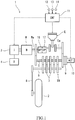
- FIG. 1 is a configuration diagram of a parallel hybrid vehicle 1 according to a first embodiment.
- the vehicle 1 is, for example, a motorcycle.
- the vehicle 1 includes an unillustrated driven wheel (front wheel) and a drive wheel 2 (rear wheel).
- the vehicle 1 includes an engine E and an electric motor M.
- the engine E and electric motor M are disposed between the front wheel (driven wheel) and rear wheel (drive wheel 2).
- the engine E is an internal combustion engine.
- the engine E serves as a drive source for travel which drives the drive wheel 2.
- the engine E serves also as an electricity generator drive source.
- the engine E is, for example, a four-stroke engine.
- the electric motor M generates power from electricity supplied from a battery 4 via an inverter 3, thus serving as a drive source for travel which drives the drive wheel 2.
- the electric motor M generates electricity from power transmitted from an input shaft 5 of a transmission TM, thus serving also as an electricity generator that electrically charges the battery 4.
- the vehicle 1 includes the transmission TM, which is configured to change the speed of rotational power output from the engine E and the electric motor M and transmit the resulting rotational power to the drive wheel 2.
- the transmission TM is, for example, a manual transmission that performs a gear-shifting process by mechanically responding to a manual operation performed by the driver of the vehicle.
- the transmission TM includes the input shaft 5, an output shaft 6, and a gear train 7.
- the input shaft 5 receives rotational power output from the engine E and the electric motor M.
- the gear train 7 changes the speed of rotation transmitted from the input shaft 5 at a selected gear ratio and transmits the resulting rotation to the output shaft 6.
- the output shaft 6 receives the rotational power resulting from the speed change by the gear train 7, and outputs this rotational power to the drive wheel 2 via an output transmission member 8 (e.g., a chain or a belt).
- an output transmission member 8 e.g., a chain or a belt
- a crankshaft Ea of the engine E, a rotation shaft Ma of the electric motor M, the input shaft 5 of the transmission TM, and the output shaft 6 of the transmission TM are arranged parallel to one another.
- the rotational power of the crankshaft Ea of the engine E is input to the input shaft 5 at one axial end (right end in FIG. 1 ) of the input shaft 5 via a main clutch 9.
- the rotational power of the rotation shaft Ma of the electric motor M is input to the input shaft 5 at the other axial end (left end in FIG. 1 ) of the input shaft 5.
- the power transmission route from the electric motor M to the input shaft 5 is different from the power transmission route from the engine E to the input shaft 5.
- the vehicle 1 includes a controller 11.
- the controller 11 includes a processor, a volatile memory, a non-volatile memory, and an I/O interface.
- the controller 11 receives output signals such as those from an accelerator operation amount sensor 12, an engine speed sensor 13, and a battery sensor 14 via the I/O interface.
- the controller 11 controls the engine E (in particular, the throttle valve, fuel injection valve, and ignition plug of the engine), the electric motor M, and the clutch actuator 10.
- the processor makes reference to information such as that obtained from the sensors 12 to 14 and performs processing operations using the volatile memory according to a program stored in the non-volatile memory, thereby controlling the engine E, the electric motor M, and the clutch actuator 10.
- the vehicle 1 includes a water pump 16 and an oil pump 17.
- the water pump 16 causes a cooling liquid to circulate in a cooling path for cooling of the engine E and the inverter 3.
- the oil pump 17 causes a lubricant oil to circulate in a lubrication path for lubrication of the engine E, the transmission TM, and other lubrication targets 18.
- the water pump 16 and the oil pump 17 are connected to the electric motor M to receive power from the electric motor M, and are therefore connected to the engine E to receive power from the engine E.
- the water pump 16 and the oil pump 17 are coaxially connected to each other.
- the drive shafts of the water pump 16 and oil pump 17 are disposed coaxially with the rotation shaft Ma of the electric motor M and are coupled to the rotation shaft Ma of the electric motor M.
- the water pump 16 and the oil pump 17 can be compactly arranged to prevent size increase of the vehicle.
- FIG. 2 is a block diagram of a cooling system 20 of the vehicle 1 of FIG. 1 .
- the cooling system 20 includes a cooling path 21 configured as a closed circuit.
- the cooling path 21 includes a common cooling path 21a, an engine cooling path 21b, and an electric component cooling path 21c.
- the common cooling path 21a extends so as to connect the water pump 16 and a radiator 22 in series.
- the engine cooling path 21b branches from the common cooling path 21a to enable cooling of the engine E.
- the engine cooling path 21b passes through a water jacket (not shown) provided for the engine E.
- the electric component cooling path 21c branches from the common cooling path 21a to enable cooling of the inverter 3 (and/or the motor M).
- the electric component cooling path 21c passes through a water jacket (not shown) provided for the inverter 3 (and/or the motor M).
- the electric component cooling path 21c may be configured to further enable cooling of the electric motor M.
- At least one valve is provided in the cooling path 21.
- the at least one valve consists of a valve 23 provided in the engine cooling path 21b.
- the valve 23 is configured to be switchable between a first state in which the valve 23 allows the engine cooling path 21b to be fully open and a second state in which the valve 23 restricts flow of the cooling liquid through the engine cooling path 21b so that the flow of the cooling liquid through the engine cooling path is less than that in the first state.
- the first state is a fully open state
- the second state is a closed state.
- the second state may be a state in which the valve is open to a smaller degree than in the first state.
- the controller 11 brings the valve 23 into the first state (open state), while when the engine E is in a non-driving state and the electric motor M is in a driving state, the controller 11 brings the valve 23 into the second state (closed state).
- the cooling liquid flows principally into the electric component cooling path 21c from the common cooling path 21a, while when the electric motor M is stopped and does not need to be cooled, the cooling liquid flows principally into the engine cooling path 21b from the common cooling path 21a. This provides improved efficiency of cooling of the drive system for travel of the parallel hybrid vehicle 1.
- a valve may be provided also in the electric component cooling path 21c. That is, a configuration may be employed in which the at least one valve provided in the cooling path 21 includes the valve 23 provided in the engine cooling path 21b and a valve (not shown) provided in the electric component cooling path 21c.
- the first state of the at least one valve provided in the cooling path 21 be a state in which the flow through the engine cooling path 21b is favored over the flow through the electric component cooling path 21c and that the second state of the at least one valve provided in the cooling path 21 be a state in which the flow through the electric component cooling path 21c is favored over the flow through the engine cooling path 21b.
- the first state may be a state in which the valve 23 of the engine cooling path 21b is open while the valve (not shown) of the electric component cooling path 21c is closed
- the second state may be a state in which the valve 23 of the engine cooling path 21b is closed while the valve (not shown) of the electric component cooling path 21c is open.
- FIG. 3 is a block diagram of a lubrication system 30 of the vehicle 1 shown in FIG. 1 .
- the lubrication system 30 includes a lubrication path 31 configured as a closed circuit.
- the lubrication path 31 includes a common lubrication path 31a, an engine lubrication path 31b, a transmission lubrication path 31c, and an additional lubrication path 31d.
- the common lubrication path 31a extends so as to connect the oil pump 17 and an oil cooler 32 in series.
- the engine lubrication path 31b branches from the common lubrication path 31a to enable lubrication of the engine E.
- the engine lubrication path 31b passes through an actuation system for intake and exhaust valves of the engine E.
- the transmission lubrication path 31c branches from the common lubrication path 31a to enable lubrication of the transmission TM.
- the transmission lubrication path 31c serves in lubrication of the gear train 7 of the transmission TM.
- the additional lubrication path 31d serves in lubrication of the other lubrication targets 18 (such as bearings).
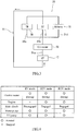
- FIG. 4 is a table illustrating the state of the vehicle 1 of FIG. 1 in different modes.
- the controller 11 selects one mode from a plurality of travel modes including an EV mode, an HEV mode, and an EGV mode, and controls the engine E, the electric motor M, and the clutch actuator 10.
- the EV mode is a mode in which the engine E is stopped and the drive wheel 2 is driven with power generated by the electric motor M.
- the clutch actuator 10 brings the main clutch 9 into a disengaged state to prevent the engine E from acting as a resistance when the electric motor M is in operation.
- the electric motor M is brought into the driving state during acceleration, while during deceleration, the electric motor M is brought into a regeneration state.
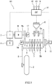
- FIG. 6 is a configuration diagram of a parallel hybrid vehicle 201 according to a third embodiment.
- the drive shaft of the water pump 16 is coupled to the crankshaft Ea of the engine E via a first one-way clutch 261.
- the first one-way clutch 261 permits transmission of power from the crankshaft Ea of the engine E to the water pump 16, and prohibits transmission of power from the water pump 16 to the crankshaft Ea of the engine E.
Landscapes
- Engineering & Computer Science (AREA)
- Chemical & Material Sciences (AREA)
- Combustion & Propulsion (AREA)
- Mechanical Engineering (AREA)
- Transportation (AREA)
- General Engineering & Computer Science (AREA)
- Hybrid Electric Vehicles (AREA)
- Electric Propulsion And Braking For Vehicles (AREA)
- Lubrication Of Internal Combustion Engines (AREA)
Abstract
Description
- The present disclosure relates to a parallel hybrid vehicle including a water pump.
- A parallel hybrid vehicle is known which includes an engine and an electric motor as drive sources for travel of the vehicle, the engine and electric motor being coupled to a drive wheel to transmit power to the drive wheel (see Japanese Laid-Open Patent Application Publication No.
H10-339185 Patent Literature 1 proposes providing an auxiliary motor separately from the drive sources for travel and driving the water pump using the auxiliary motor during stoppage of the engine. - With the configuration of
Patent Literature 1, however, the need for additionally providing the auxiliary motor for the water pump leads to reduction in the component-mounting space of the vehicle and also to increase in the vehicle weight and component cost. - It is an object of the present disclosure to ensure the maintenance of the function of a water pump in a parallel hybrid vehicle and at the same time achieve improvement in the use efficiency of the component-mounting space of the vehicle and reduction in the vehicle weight and component cost.
- A parallel hybrid vehicle according to an aspect of the present disclosure includes: an engine serving as a drive source for travel of the parallel hybrid vehicle; an electric motor serving as a drive source for travel of the parallel hybrid vehicle; and a water pump that causes a cooling liquid to circulate in a cooling path, wherein the water pump is connected to the engine to receive power from the engine and is connected to the electric motor to receive power from the electric motor.
- With the above configuration, the water pump is driven by rotational power of the engine when the engine is in operation, while when the electric motor is in operation, the water pump is driven by rotational power of the electric motor. Thus, the water pump is driven by the electric motor when the engine is not in operation and by the engine when the electric motor is not in operation. In the parallel hybrid vehicle, therefore, the water pump can be driven even during stoppage of the engine, and the need for an auxiliary motor dedicated for driving of the water pump can be eliminated. Consequently, the use efficiency of the component-mounting space of the vehicle can be improved, and the vehicle weight and component cost can be reduced.
- In an example, the vehicle may further include a transmission including an input shaft, an output shaft, and a gear train, the transmission being configured to change the speed of rotational power output from the engine and the electric motor at a selected gear ratio and configured to output the resulting rotational power to a drive wheel. In this example, rotational power of the engine may be transmitted to the electric motor via the input shaft of the transmission, and the water pump may be connected to the electric motor to receive power from the electric motor.
- With this configuration, the engine can drive the water pump by means of the transmission during stoppage of the electric motor.
- In an example, the vehicle may further include: a main clutch provided in a power transmission route between a crankshaft of the engine and the input shaft of the transmission; a first one-way clutch that permits transmission of power from the engine to the water pump; and a second one-way clutch that permits transmission of power from the electric motor to the water pump.
- With this configuration, the water pump connected to the electric motor can be driven with power transmitted from the engine even when the main clutch is disengaged.
- In an example, a first power transmission route for power transmission from the engine to the water pump via the first one-way clutch and a second power transmission route for power transmission from the electric motor to the water pump via the second one-way clutch may be different from a power transmission route of the transmission.
- With this configuration, the flexibility in arrangement of the water pump can be increased while the transmission is kept compact.
- In an example, a crankshaft of the engine, a rotation shaft of the electric motor, the input shaft of the transmission, and the output shaft of the transmission may be arranged parallel to one another, and a drive shaft of the water pump may be disposed coaxially with or parallel to one of the crankshaft, the rotation shaft, the input shaft, and the output shaft.
- With this configuration, the space efficiency in arrangement of the transmission mechanism and the water pump can be improved, and the improved space efficiency can contribute to size reduction of the vehicle.
- In an example, the vehicle may further include an oil pump that causes a lubricant oil to circulate in a lubrication path, and the water pump and the oil pump may be coaxially connected to each other.
- With this configuration, the need for an auxiliary motor dedicated for driving of the water pump and the oil pump is eliminated, and the cooling liquid and the lubricant oil can be circulated both when the engine is not in operation and when the electric motor is not in operation. Additionally, the space efficiency can be improved.
- In an example, the vehicle may further include: an inverter operable to bring the electric motor into operation; a radiator provided in the cooling path; and at least one valve provided in the cooling path, wherein the cooling path includes: a common cooling path passing through the radiator; an engine cooling path branching from the common cooling path to enable cooling of the engine; and an electric component cooling path branching from the common cooling path to enable cooling of at least one of the electric motor and the inverter, the valve is switchable between a first state in which the valve allows the engine cooling path to be open and a second state in which the valve restricts flow of the cooling liquid through the engine cooling path so that the flow of the cooling liquid through the engine cooling path is less than that in the first state, the valve is in the first state when the electric motor is in a non-driving state and the engine is in a driving state, and the valve is in the second state when the engine is in a non-driving state and the electric motor is in a driving state.
- With this configuration, when the engine is stopped and does not need to be cooled, the flow of the cooling liquid from the common cooling path into the engine cooling path is restricted, while when the engine is in operation and needs to be cooled, the flow of the cooling liquid from the common cooling path into the engine cooling path is promoted. This provides improved efficiency of cooling of the drive system for travel of the parallel hybrid vehicle.
- The above and further objects, features and advantages of the present disclosure will be more apparent from the following detailed description of preferred embodiments with reference to the accompanying drawings.
-
-
FIG. 1 is a configuration diagram of a parallel hybrid vehicle according to a first embodiment. -
FIG. 2 is a block diagram of a cooling system of the vehicle ofFIG. 1 . -
FIG. 3 is a block diagram of a lubrication system of the vehicle ofFIG. 1 . -
FIG. 4 is a table illustrating the state of the vehicle ofFIG. 1 in different modes. -
FIG. 5 is a configuration diagram of a parallel hybrid vehicle according to a second embodiment. -
FIG. 6 is a configuration diagram of a parallel hybrid vehicle according to a third embodiment. - Hereinafter, embodiments will be described with reference to the drawings.
-
FIG. 1 is a configuration diagram of aparallel hybrid vehicle 1 according to a first embodiment. As shown inFIG. 1 , thevehicle 1 is, for example, a motorcycle. Thevehicle 1 includes an unillustrated driven wheel (front wheel) and a drive wheel 2 (rear wheel). Thevehicle 1 includes an engine E and an electric motor M. The engine E and electric motor M are disposed between the front wheel (driven wheel) and rear wheel (drive wheel 2). - The engine E is an internal combustion engine. The engine E serves as a drive source for travel which drives the
drive wheel 2. The engine E serves also as an electricity generator drive source. The engine E is, for example, a four-stroke engine. - The electric motor M generates power from electricity supplied from a
battery 4 via aninverter 3, thus serving as a drive source for travel which drives thedrive wheel 2. The electric motor M generates electricity from power transmitted from an input shaft 5 of a transmission TM, thus serving also as an electricity generator that electrically charges thebattery 4. - The
vehicle 1 includes the transmission TM, which is configured to change the speed of rotational power output from the engine E and the electric motor M and transmit the resulting rotational power to thedrive wheel 2. The transmission TM is, for example, a manual transmission that performs a gear-shifting process by mechanically responding to a manual operation performed by the driver of the vehicle. The transmission TM includes the input shaft 5, anoutput shaft 6, and agear train 7. The input shaft 5 receives rotational power output from the engine E and the electric motor M. Thegear train 7 changes the speed of rotation transmitted from the input shaft 5 at a selected gear ratio and transmits the resulting rotation to theoutput shaft 6. Theoutput shaft 6 receives the rotational power resulting from the speed change by thegear train 7, and outputs this rotational power to thedrive wheel 2 via an output transmission member 8 (e.g., a chain or a belt). - A crankshaft Ea of the engine E, a rotation shaft Ma of the electric motor M, the input shaft 5 of the transmission TM, and the
output shaft 6 of the transmission TM are arranged parallel to one another. The rotational power of the crankshaft Ea of the engine E is input to the input shaft 5 at one axial end (right end inFIG. 1 ) of the input shaft 5 via amain clutch 9. The rotational power of the rotation shaft Ma of the electric motor M is input to the input shaft 5 at the other axial end (left end inFIG. 1 ) of the input shaft 5. Thus, the power transmission route from the electric motor M to the input shaft 5 is different from the power transmission route from the engine E to the input shaft 5. - With the
main clutch 9 engaged, the rotational power of the crankshaft Ea of the engine E is transmitted to the electric motor M via the input shaft 5 of the transmission TM. Thus, the rotational power of the crankshaft Ea of the engine E can cause the electric motor M to operate for electricity generation or cause the electric motor M to run idle in a state where the circuit of the electric motor M is open. With themain clutch 9 disengaged, the rotational power of the rotation shaft Ma of the electric motor M is not transmitted to the engine E. Thus, when the electric motor M is in operation, themain clutch 9 can be disengaged to prevent the engine E from acting as a resistance. - The main clutch 9 (e.g., a multi-plate clutch) is provided in the power transmission route between the crankshaft Ea of the engine E and the input shaft 5 of the transmission TM. The
main clutch 9 is actuated by aclutch actuator 10 to be disengaged and engaged. The power transmission route between the rotation shaft Ma of the electric motor M and the input shaft 5 of the transmission TM is constantly kept in a power transmission state. - The
vehicle 1 includes acontroller 11. Thecontroller 11 includes a processor, a volatile memory, a non-volatile memory, and an I/O interface. Thecontroller 11 receives output signals such as those from an acceleratoroperation amount sensor 12, anengine speed sensor 13, and abattery sensor 14 via the I/O interface. Thecontroller 11 controls the engine E (in particular, the throttle valve, fuel injection valve, and ignition plug of the engine), the electric motor M, and theclutch actuator 10. The processor makes reference to information such as that obtained from thesensors 12 to 14 and performs processing operations using the volatile memory according to a program stored in the non-volatile memory, thereby controlling the engine E, the electric motor M, and theclutch actuator 10. - The
vehicle 1 includes awater pump 16 and anoil pump 17. Thewater pump 16 causes a cooling liquid to circulate in a cooling path for cooling of the engine E and theinverter 3. Theoil pump 17 causes a lubricant oil to circulate in a lubrication path for lubrication of the engine E, the transmission TM, and other lubrication targets 18. Thewater pump 16 and theoil pump 17 are connected to the electric motor M to receive power from the electric motor M, and are therefore connected to the engine E to receive power from the engine E. In the present embodiment, thewater pump 16 and theoil pump 17 are coaxially connected to each other. The drive shafts of thewater pump 16 andoil pump 17 are disposed coaxially with the rotation shaft Ma of the electric motor M and are coupled to the rotation shaft Ma of the electric motor M. Thus, thewater pump 16 and theoil pump 17 can be compactly arranged to prevent size increase of the vehicle. -
FIG. 2 is a block diagram of acooling system 20 of thevehicle 1 ofFIG. 1 . As shown inFIG. 2 , thecooling system 20 includes acooling path 21 configured as a closed circuit. The coolingpath 21 includes acommon cooling path 21a, anengine cooling path 21b, and an electriccomponent cooling path 21c. Thecommon cooling path 21a extends so as to connect thewater pump 16 and aradiator 22 in series. Theengine cooling path 21b branches from thecommon cooling path 21a to enable cooling of the engine E. For example, theengine cooling path 21b passes through a water jacket (not shown) provided for the engine E. The electriccomponent cooling path 21c branches from thecommon cooling path 21a to enable cooling of the inverter 3 (and/or the motor M). For example, the electriccomponent cooling path 21c passes through a water jacket (not shown) provided for the inverter 3 (and/or the motor M). The electriccomponent cooling path 21c may be configured to further enable cooling of the electric motor M. - At least one valve is provided in the
cooling path 21. Referring toFIG. 2 , the at least one valve consists of a valve 23 provided in theengine cooling path 21b. The valve 23 is configured to be switchable between a first state in which the valve 23 allows theengine cooling path 21b to be fully open and a second state in which the valve 23 restricts flow of the cooling liquid through theengine cooling path 21b so that the flow of the cooling liquid through the engine cooling path is less than that in the first state. In the present embodiment, the first state is a fully open state, and the second state is a closed state. The second state may be a state in which the valve is open to a smaller degree than in the first state. - When the electric motor M is in a non-driving state and the engine E is in a driving state, the
controller 11 brings the valve 23 into the first state (open state), while when the engine E is in a non-driving state and the electric motor M is in a driving state, thecontroller 11 brings the valve 23 into the second state (closed state). Thus, when the engine E is stopped and does not need to be cooled, the cooling liquid flows principally into the electriccomponent cooling path 21c from thecommon cooling path 21a, while when the electric motor M is stopped and does not need to be cooled, the cooling liquid flows principally into theengine cooling path 21b from thecommon cooling path 21a. This provides improved efficiency of cooling of the drive system for travel of theparallel hybrid vehicle 1. - Alternatively, a valve may be provided also in the electric
component cooling path 21c. That is, a configuration may be employed in which the at least one valve provided in thecooling path 21 includes the valve 23 provided in theengine cooling path 21b and a valve (not shown) provided in the electriccomponent cooling path 21c. In this case, it is advantageous that the first state of the at least one valve provided in thecooling path 21 be a state in which the flow through theengine cooling path 21b is favored over the flow through the electriccomponent cooling path 21c and that the second state of the at least one valve provided in thecooling path 21 be a state in which the flow through the electriccomponent cooling path 21c is favored over the flow through theengine cooling path 21b. Specifically, the first state may be a state in which the valve 23 of theengine cooling path 21b is open while the valve (not shown) of the electriccomponent cooling path 21c is closed, and the second state may be a state in which the valve 23 of theengine cooling path 21b is closed while the valve (not shown) of the electriccomponent cooling path 21c is open. -
FIG. 3 is a block diagram of alubrication system 30 of thevehicle 1 shown inFIG. 1 . As shown inFIG. 3 , thelubrication system 30 includes alubrication path 31 configured as a closed circuit. Thelubrication path 31 includes acommon lubrication path 31a, anengine lubrication path 31b, atransmission lubrication path 31c, and anadditional lubrication path 31d. Thecommon lubrication path 31a extends so as to connect theoil pump 17 and an oil cooler 32 in series. Theengine lubrication path 31b branches from thecommon lubrication path 31a to enable lubrication of the engine E. For example, theengine lubrication path 31b passes through an actuation system for intake and exhaust valves of the engine E. Thetransmission lubrication path 31c branches from thecommon lubrication path 31a to enable lubrication of the transmission TM. For example, thetransmission lubrication path 31c serves in lubrication of thegear train 7 of the transmission TM. Theadditional lubrication path 31d serves in lubrication of the other lubrication targets 18 (such as bearings). -
FIG. 4 is a table illustrating the state of thevehicle 1 ofFIG. 1 in different modes. In theparallel hybrid vehicle 1, as shown inFIG. 4 , thecontroller 11 selects one mode from a plurality of travel modes including an EV mode, an HEV mode, and an EGV mode, and controls the engine E, the electric motor M, and theclutch actuator 10. - The EV mode is a mode in which the engine E is stopped and the
drive wheel 2 is driven with power generated by the electric motor M. In the EV mode, theclutch actuator 10 brings themain clutch 9 into a disengaged state to prevent the engine E from acting as a resistance when the electric motor M is in operation. In the EV mode, the electric motor M is brought into the driving state during acceleration, while during deceleration, the electric motor M is brought into a regeneration state. - The HEV mode is a mode in which the
drive wheel 2 is driven with power generated by the electric motor M and the engine E. In the HEV mode, theclutch actuator 10 brings themain clutch 9 into an engaged state to allow the rotational power of the engine E to be transmitted to thedrive wheel 2 via the transmission TM. In the HEV mode, the electric motor M is brought into the driving state during acceleration, while during deceleration, the electric motor M is brought into a regeneration state. - The EGV mode is a mode in which the engine E is brought into operation with the electric motor M not in operation so as to drive the
drive wheel 2 only with rotational power of the engine E. In the EGV mode, theclutch actuator 10 brings themain clutch 9 into an engaged state to allow the rotational power of the engine E to be transmitted to thedrive wheel 2 via the transmission TM. In the EGV mode, the electric motor M is in a regeneration state or an idle running state (free state) both during acceleration and during deceleration. That is, in the EGV mode, power of the engine E is transmitted to the electric motor M via the input shaft 5, and thus the rotation shaft Ma of the electric motor M is rotated although the electric motor M is not brought into operation. - In the
parallel hybrid vehicle 1, as seen from the table ofFIG. 4 , thewater pump 16 andoil pump 17 are driven by rotational power of the engine E when the engine E is in operation, while when the electric motor M is in operation, thewater pump 16 andoil pump 17 are driven by rotational power of the electric motor M. Thus, thewater pump 16 andoil pump 17 are driven by the electric motor M when the engine E is not in operation and by the engine E when the electric motor M is not in operation. In theparallel hybrid vehicle 1, therefore, thewater pump 16 andoil pump 17 can be driven even during stoppage of the engine E, and the need for an auxiliary motor dedicated for driving of thewater pump 16 andoil pump 17 can be eliminated. Consequently, the use efficiency of the component-mounting space of the vehicle can be improved, and the vehicle weight and component cost can be reduced. -
FIG. 5 is a configuration diagram of aparallel hybrid vehicle 101 according to a second embodiment. In theparallel hybrid vehicle 101 of the second embodiment, as seen fromFIG. 5 , thewater pump 16 is disposed in a different way. In theparallel hybrid vehicle 101, the drive shaft of thewater pump 16 is disposed coaxially with, and coupled to, the input shaft 5 of the transmission TM. The drive shaft of theoil pump 17 is disposed coaxially with, and coupled to, the rotation shaft Ma of the electric motor M. With this configuration, as in the first embodiment, thewater pump 16 andoil pump 17 can be driven irrespective of the travel mode and without the need for providing an auxiliary motor dedicated for driving of thewater pump 16 andoil pump 17. The other elements are the same as those of the first embodiment described above. The same elements are denoted by the same reference signs and will not be described again. -
FIG. 6 is a configuration diagram of aparallel hybrid vehicle 201 according to a third embodiment. In theparallel hybrid vehicle 201 of the third embodiment, as shown inFIG. 6 , the drive shaft of thewater pump 16 is coupled to the crankshaft Ea of the engine E via a first one-way clutch 261. The first one-way clutch 261 permits transmission of power from the crankshaft Ea of the engine E to thewater pump 16, and prohibits transmission of power from thewater pump 16 to the crankshaft Ea of the engine E. - The drive shaft of the
water pump 16 is coupled to the rotation shaft Ma of the electric motor M via a second one-way clutch 262. The second one-way clutch 262 permits transmission of power from the rotation shaft Ma of the electric motor M to thewater pump 16, and prohibits transmission of power from thewater pump 16 to the rotation shaft Ma of the electric motor M. The drive shaft of theoil pump 17 is coupled to the drive shaft of thewater pump 16. For example, the drive shaft of theoil pump 17 is disposed coaxially with the drive shaft of thewater pump 16. - With this configuration, the
water pump 16 andoil pump 17 connected to the electric motor M can be driven with power transmitted from the engine E even when themain clutch 9 is disengaged. - Additionally, a first
power transmission route 251 for power transmission from the engine E to thewater pump 16 via the first one-way clutch 261 and a secondpower transmission route 252 for power transmission from the electric motor M to thewater pump 16 via the second one-way clutch 262 are different from the power transmission route of the transmission TM. Thus, the flexibility in arrangement of thewater pump 16 andoil pump 17 can be increased while the transmission TM is kept compact. The other elements are the same as those of the first embodiment described above. The same elements are denoted by the same reference signs and will not be described again. - Many modifications and other embodiments of the present invention will be apparent to those skilled in the art from the foregoing description. Accordingly, the foregoing description is to be construed as illustrative only, and is provided for the purpose of teaching those skilled in the art the best mode for carrying out the invention.
- The details of the structure and/or function may be varied substantially without departing from the scope of the invention.
Claims (7)
- A parallel hybrid vehicle comprising:an engine serving as a drive source for travel of the parallel hybrid vehicle;an electric motor serving as a drive source for travel of the parallel hybrid vehicle; anda water pump that causes a cooling liquid to circulate in a cooling path, whereinthe water pump is connected to the engine to receive power from the engine and is connected to the electric motor to receive power from the electric motor.
- The parallel hybrid vehicle according to claim 1, further comprising a transmission comprising an input shaft, an output shaft, and a gear train, the transmission being configured to change the speed of rotational power output from the engine and the electric motor at a selected gear ratio and configured to output the resulting rotational power to a drive wheel, wherein
rotational power of the engine is transmitted to the electric motor via the input shaft of the transmission, and
the water pump is connected to the electric motor to receive power from the electric motor. - The parallel hybrid vehicle according to claim 2, further comprising:a main clutch provided in a power transmission route between a crankshaft of the engine and the input shaft of the transmission;a first one-way clutch that permits transmission of power from the engine to the water pump; anda second one-way clutch that permits transmission of power from the electric motor to the water pump.
- The parallel hybrid vehicle according to claim 3, wherein a first power transmission route for power transmission from the engine to the water pump via the first one-way clutch and a second power transmission route for power transmission from the electric motor to the water pump via the second one-way clutch are different from a power transmission route of the transmission.
- The parallel hybrid vehicle according to any one of claims 2 to 4, wherein
a crankshaft of the engine, a rotation shaft of the electric motor, the input shaft of the transmission, and the output shaft of the transmission are arranged parallel to one another, and
a drive shaft of the water pump is disposed coaxially with or parallel to one of the crankshaft, the rotation shaft, the input shaft, and the output shaft. - The parallel hybrid vehicle according to any one of claims 1 to 5, further comprising an oil pump that causes a lubricant oil to circulate in a lubrication path, wherein
the water pump and the oil pump are coaxially connected to each other. - The parallel hybrid vehicle according to any one of claims 1 to 6, further comprising:an inverter operable to bring the electric motor into operation;a radiator provided in the cooling path; andat least one valve provided in the cooling path, whereinthe cooling path comprises: a common cooling path passing through the radiator; an engine cooling path branching from the common cooling path to enable cooling of the engine; and an electric component cooling path branching from the common cooling path to enable cooling of at least one of the electric motor and the inverter,the valve is switchable between a first state in which the valve allows the engine cooling path to be open and a second state in which the valve restricts flow of the cooling liquid through the engine cooling path so that the flow of the cooling liquid through the engine cooling path is less than that in the first state,the valve is in the first state when the electric motor is in a non-driving state and the engine is in a driving state, andthe valve is in the second state when the engine is in a non-driving state and the electric motor is in a driving state.
Applications Claiming Priority (1)
| Application Number | Priority Date | Filing Date | Title |
|---|---|---|---|
| JP2018227335A JP7235489B2 (en) | 2018-12-04 | 2018-12-04 | parallel hybrid vehicle |
Publications (2)
| Publication Number | Publication Date |
|---|---|
| EP3663117A1 true EP3663117A1 (en) | 2020-06-10 |
| EP3663117B1 EP3663117B1 (en) | 2022-02-23 |
Family
ID=68732867
Family Applications (1)
| Application Number | Title | Priority Date | Filing Date |
|---|---|---|---|
| EP19212446.9A Active EP3663117B1 (en) | 2018-12-04 | 2019-11-29 | Parallel hybrid motorcycle |
Country Status (3)
| Country | Link |
|---|---|
| US (1) | US11041427B2 (en) |
| EP (1) | EP3663117B1 (en) |
| JP (1) | JP7235489B2 (en) |
Families Citing this family (5)
| Publication number | Priority date | Publication date | Assignee | Title |
|---|---|---|---|---|
| JP6894734B2 (en) * | 2017-03-22 | 2021-06-30 | 川崎重工業株式会社 | Hybrid vehicle |
| CN110601451B (en) * | 2019-09-18 | 2024-07-05 | 精进电动科技股份有限公司 | An engine and motor assembly |
| JP7594422B2 (en) * | 2020-12-08 | 2024-12-04 | カワサキモータース株式会社 | Power unit and vehicle equipped with power unit |
| CN116971855B (en) * | 2022-04-24 | 2024-12-10 | 比亚迪股份有限公司 | Cooling lubrication system and vehicle having the same |
| CN115972891B (en) * | 2022-12-31 | 2026-05-26 | 东风商用车有限公司 | Cooling systems that reuse motor coolant and hybrid vehicles |
Citations (5)
| Publication number | Priority date | Publication date | Assignee | Title |
|---|---|---|---|---|
| JPH10339185A (en) | 1997-06-06 | 1998-12-22 | Nissan Motor Co Ltd | Combined vehicle drive device of internal combustion engine and electric motor and control method therefor |
| US20120173063A1 (en) * | 2010-12-31 | 2012-07-05 | Mahesh Madurai Kumar | Hybrid vehicle powertrain cooling system |
| EP2527177A1 (en) * | 2010-01-12 | 2012-11-28 | Honda Motor Co., Ltd. | Driving force transmission device for hybrid vehicle |
| US20150354447A1 (en) * | 2014-06-09 | 2015-12-10 | Schaeffler Technologies AG & Co. KG | Accessories drive system including a transmission driven motor generator unit |
| US20180050686A1 (en) * | 2016-08-17 | 2018-02-22 | GM Global Technology Operations LLC | Hybrid Vehicle Propulsion Systems And Methods |
Family Cites Families (9)
| Publication number | Priority date | Publication date | Assignee | Title |
|---|---|---|---|---|
| DE19934790A1 (en) * | 1999-07-27 | 2001-02-08 | Bosch Gmbh Robert | Drive system for motor vehicles |
| US20030116368A1 (en) * | 2001-12-20 | 2003-06-26 | Winkelman James R. | Accessory drive for vehicle with hybrid drive system |
| US6668766B1 (en) * | 2002-07-22 | 2003-12-30 | Visteon Global Technologies, Inc. | Vehicle engine cooling system with variable speed water pump |
| CN102007302B (en) * | 2008-04-17 | 2013-05-22 | 博格华纳公司 | coolant pump |
| JP2011178280A (en) * | 2010-03-01 | 2011-09-15 | Honda Motor Co Ltd | Power transmission device for hybrid vehicle and control method for the same |
| US8978600B2 (en) * | 2012-04-11 | 2015-03-17 | Borgwarner Inc. | Control methods for dual mode cooling pump |
| JP5915008B2 (en) * | 2011-06-30 | 2016-05-11 | いすゞ自動車株式会社 | Hybrid vehicle |
| JP5929678B2 (en) * | 2012-10-04 | 2016-06-08 | 株式会社デンソー | Control device for hybrid vehicle |
| DE102013105026B4 (en) * | 2013-05-16 | 2024-06-20 | Dr. Ing. H.C. F. Porsche Aktiengesellschaft | Drivetrain for a hybrid vehicle |
-
2018
- 2018-12-04 JP JP2018227335A patent/JP7235489B2/en active Active
-
2019
- 2019-11-21 US US16/690,406 patent/US11041427B2/en active Active
- 2019-11-29 EP EP19212446.9A patent/EP3663117B1/en active Active
Patent Citations (5)
| Publication number | Priority date | Publication date | Assignee | Title |
|---|---|---|---|---|
| JPH10339185A (en) | 1997-06-06 | 1998-12-22 | Nissan Motor Co Ltd | Combined vehicle drive device of internal combustion engine and electric motor and control method therefor |
| EP2527177A1 (en) * | 2010-01-12 | 2012-11-28 | Honda Motor Co., Ltd. | Driving force transmission device for hybrid vehicle |
| US20120173063A1 (en) * | 2010-12-31 | 2012-07-05 | Mahesh Madurai Kumar | Hybrid vehicle powertrain cooling system |
| US20150354447A1 (en) * | 2014-06-09 | 2015-12-10 | Schaeffler Technologies AG & Co. KG | Accessories drive system including a transmission driven motor generator unit |
| US20180050686A1 (en) * | 2016-08-17 | 2018-02-22 | GM Global Technology Operations LLC | Hybrid Vehicle Propulsion Systems And Methods |
Also Published As
| Publication number | Publication date |
|---|---|
| US20200173341A1 (en) | 2020-06-04 |
| EP3663117B1 (en) | 2022-02-23 |
| US11041427B2 (en) | 2021-06-22 |
| JP2020090137A (en) | 2020-06-11 |
| JP7235489B2 (en) | 2023-03-08 |
Similar Documents
| Publication | Publication Date | Title |
|---|---|---|
| US11041427B2 (en) | Parallel hybrid vehicle | |
| CN203511265U (en) | Power train of motor vehicle and with internal combustion engine and starting electric generator | |
| EP1586477B1 (en) | Arrangement of motor-generator in a vehicule | |
| US6306056B1 (en) | Dual engine hybrid electric vehicle | |
| CN106828078B (en) | Cooling device for vehicle | |
| US10124796B2 (en) | Hybrid vehicle system | |
| JP4139294B2 (en) | Hybrid electric vehicle cooling system and method | |
| US7748483B2 (en) | Accessory drive system and method for a parallel electric hybrid vehicle | |
| US7954580B2 (en) | Accessory drive system and method for a belt-alternator-starter electric hybrid vehicle | |
| US6949041B2 (en) | Vehicle driving system | |
| US10953865B2 (en) | Modular hybrid transmission with torque converter baffle | |
| CN110072722A (en) | Transmission mounted charging system with engine stall slip and dual mode HVAC | |
| KR20150008029A (en) | Hybrid electric vehicle powertrain | |
| JP2017100700A (en) | Vehicular cooling apparatus | |
| CN110366500A (en) | Hybrid powertrain for hybrid vehicles | |
| US10892668B2 (en) | Cooling systems for cooling electric machines within electrified vehicles | |
| CN107415684A (en) | Hybrid electric drive system | |
| CN114771493A (en) | Hybrid vehicle transmission shift control for electric machine thermal management | |
| US9352738B2 (en) | Dual clutch powertrain architecture | |
| CN104709069B (en) | The front-end module of hybrid vehicle | |
| RU96541U1 (en) | DEVICE FOR OPERATING HYBRID POWER PLANT WITH STARTER-GENERATOR DEVICE | |
| JP2012081793A (en) | Control device for hybrid vehicle | |
| CN111204322A (en) | Control device for hybrid vehicle | |
| CN108602424B (en) | hybrid vehicle | |
| JP2012192885A (en) | Control apparatus for hybrid vehicle |
Legal Events
| Date | Code | Title | Description |
|---|---|---|---|
| PUAI | Public reference made under article 153(3) epc to a published international application that has entered the european phase |
Free format text: ORIGINAL CODE: 0009012 |
|
| STAA | Information on the status of an ep patent application or granted ep patent |
Free format text: STATUS: REQUEST FOR EXAMINATION WAS MADE |
|
| 17P | Request for examination filed |
Effective date: 20191129 |
|
| AK | Designated contracting states |
Kind code of ref document: A1 Designated state(s): AL AT BE BG CH CY CZ DE DK EE ES FI FR GB GR HR HU IE IS IT LI LT LU LV MC MK MT NL NO PL PT RO RS SE SI SK SM TR |
|
| AX | Request for extension of the european patent |
Extension state: BA ME |
|
| STAA | Information on the status of an ep patent application or granted ep patent |
Free format text: STATUS: EXAMINATION IS IN PROGRESS |
|
| 17Q | First examination report despatched |
Effective date: 20210208 |
|
| GRAP | Despatch of communication of intention to grant a patent |
Free format text: ORIGINAL CODE: EPIDOSNIGR1 |
|
| STAA | Information on the status of an ep patent application or granted ep patent |
Free format text: STATUS: GRANT OF PATENT IS INTENDED |
|
| INTG | Intention to grant announced |
Effective date: 20210909 |
|
| GRAS | Grant fee paid |
Free format text: ORIGINAL CODE: EPIDOSNIGR3 |
|
| GRAA | (expected) grant |
Free format text: ORIGINAL CODE: 0009210 |
|
| STAA | Information on the status of an ep patent application or granted ep patent |
Free format text: STATUS: THE PATENT HAS BEEN GRANTED |
|
| AK | Designated contracting states |
Kind code of ref document: B1 Designated state(s): AL AT BE BG CH CY CZ DE DK EE ES FI FR GB GR HR HU IE IS IT LI LT LU LV MC MK MT NL NO PL PT RO RS SE SI SK SM TR |
|
| REG | Reference to a national code |
Ref country code: GB Ref legal event code: FG4D |
|
| REG | Reference to a national code |
Ref country code: CH Ref legal event code: EP |
|
| REG | Reference to a national code |
Ref country code: AT Ref legal event code: REF Ref document number: 1470200 Country of ref document: AT Kind code of ref document: T Effective date: 20220315 |
|
| REG | Reference to a national code |
Ref country code: IE Ref legal event code: FG4D |
|
| REG | Reference to a national code |
Ref country code: DE Ref legal event code: R096 Ref document number: 602019011839 Country of ref document: DE |
|
| RAP2 | Party data changed (patent owner data changed or rights of a patent transferred) |
Owner name: KAWASAKI MOTORS, LTD. |
|
| REG | Reference to a national code |
Ref country code: LT Ref legal event code: MG9D |
|
| REG | Reference to a national code |
Ref country code: NL Ref legal event code: MP Effective date: 20220223 |
|
| REG | Reference to a national code |
Ref country code: AT Ref legal event code: MK05 Ref document number: 1470200 Country of ref document: AT Kind code of ref document: T Effective date: 20220223 |
|
| PG25 | Lapsed in a contracting state [announced via postgrant information from national office to epo] |
Ref country code: SE Free format text: LAPSE BECAUSE OF FAILURE TO SUBMIT A TRANSLATION OF THE DESCRIPTION OR TO PAY THE FEE WITHIN THE PRESCRIBED TIME-LIMIT Effective date: 20220223 Ref country code: RS Free format text: LAPSE BECAUSE OF FAILURE TO SUBMIT A TRANSLATION OF THE DESCRIPTION OR TO PAY THE FEE WITHIN THE PRESCRIBED TIME-LIMIT Effective date: 20220223 Ref country code: PT Free format text: LAPSE BECAUSE OF FAILURE TO SUBMIT A TRANSLATION OF THE DESCRIPTION OR TO PAY THE FEE WITHIN THE PRESCRIBED TIME-LIMIT Effective date: 20220623 Ref country code: NO Free format text: LAPSE BECAUSE OF FAILURE TO SUBMIT A TRANSLATION OF THE DESCRIPTION OR TO PAY THE FEE WITHIN THE PRESCRIBED TIME-LIMIT Effective date: 20220523 Ref country code: NL Free format text: LAPSE BECAUSE OF FAILURE TO SUBMIT A TRANSLATION OF THE DESCRIPTION OR TO PAY THE FEE WITHIN THE PRESCRIBED TIME-LIMIT Effective date: 20220223 Ref country code: LT Free format text: LAPSE BECAUSE OF FAILURE TO SUBMIT A TRANSLATION OF THE DESCRIPTION OR TO PAY THE FEE WITHIN THE PRESCRIBED TIME-LIMIT Effective date: 20220223 Ref country code: HR Free format text: LAPSE BECAUSE OF FAILURE TO SUBMIT A TRANSLATION OF THE DESCRIPTION OR TO PAY THE FEE WITHIN THE PRESCRIBED TIME-LIMIT Effective date: 20220223 Ref country code: ES Free format text: LAPSE BECAUSE OF FAILURE TO SUBMIT A TRANSLATION OF THE DESCRIPTION OR TO PAY THE FEE WITHIN THE PRESCRIBED TIME-LIMIT Effective date: 20220223 Ref country code: BG Free format text: LAPSE BECAUSE OF FAILURE TO SUBMIT A TRANSLATION OF THE DESCRIPTION OR TO PAY THE FEE WITHIN THE PRESCRIBED TIME-LIMIT Effective date: 20220523 |
|
| PG25 | Lapsed in a contracting state [announced via postgrant information from national office to epo] |
Ref country code: PL Free format text: LAPSE BECAUSE OF FAILURE TO SUBMIT A TRANSLATION OF THE DESCRIPTION OR TO PAY THE FEE WITHIN THE PRESCRIBED TIME-LIMIT Effective date: 20220223 Ref country code: LV Free format text: LAPSE BECAUSE OF FAILURE TO SUBMIT A TRANSLATION OF THE DESCRIPTION OR TO PAY THE FEE WITHIN THE PRESCRIBED TIME-LIMIT Effective date: 20220223 Ref country code: GR Free format text: LAPSE BECAUSE OF FAILURE TO SUBMIT A TRANSLATION OF THE DESCRIPTION OR TO PAY THE FEE WITHIN THE PRESCRIBED TIME-LIMIT Effective date: 20220524 Ref country code: FI Free format text: LAPSE BECAUSE OF FAILURE TO SUBMIT A TRANSLATION OF THE DESCRIPTION OR TO PAY THE FEE WITHIN THE PRESCRIBED TIME-LIMIT Effective date: 20220223 Ref country code: AT Free format text: LAPSE BECAUSE OF FAILURE TO SUBMIT A TRANSLATION OF THE DESCRIPTION OR TO PAY THE FEE WITHIN THE PRESCRIBED TIME-LIMIT Effective date: 20220223 |
|
| PG25 | Lapsed in a contracting state [announced via postgrant information from national office to epo] |
Ref country code: IS Free format text: LAPSE BECAUSE OF FAILURE TO SUBMIT A TRANSLATION OF THE DESCRIPTION OR TO PAY THE FEE WITHIN THE PRESCRIBED TIME-LIMIT Effective date: 20220623 |
|
| PG25 | Lapsed in a contracting state [announced via postgrant information from national office to epo] |
Ref country code: SM Free format text: LAPSE BECAUSE OF FAILURE TO SUBMIT A TRANSLATION OF THE DESCRIPTION OR TO PAY THE FEE WITHIN THE PRESCRIBED TIME-LIMIT Effective date: 20220223 Ref country code: SK Free format text: LAPSE BECAUSE OF FAILURE TO SUBMIT A TRANSLATION OF THE DESCRIPTION OR TO PAY THE FEE WITHIN THE PRESCRIBED TIME-LIMIT Effective date: 20220223 Ref country code: RO Free format text: LAPSE BECAUSE OF FAILURE TO SUBMIT A TRANSLATION OF THE DESCRIPTION OR TO PAY THE FEE WITHIN THE PRESCRIBED TIME-LIMIT Effective date: 20220223 Ref country code: EE Free format text: LAPSE BECAUSE OF FAILURE TO SUBMIT A TRANSLATION OF THE DESCRIPTION OR TO PAY THE FEE WITHIN THE PRESCRIBED TIME-LIMIT Effective date: 20220223 Ref country code: DK Free format text: LAPSE BECAUSE OF FAILURE TO SUBMIT A TRANSLATION OF THE DESCRIPTION OR TO PAY THE FEE WITHIN THE PRESCRIBED TIME-LIMIT Effective date: 20220223 Ref country code: CZ Free format text: LAPSE BECAUSE OF FAILURE TO SUBMIT A TRANSLATION OF THE DESCRIPTION OR TO PAY THE FEE WITHIN THE PRESCRIBED TIME-LIMIT Effective date: 20220223 |
|
| REG | Reference to a national code |
Ref country code: DE Ref legal event code: R097 Ref document number: 602019011839 Country of ref document: DE |
|
| PG25 | Lapsed in a contracting state [announced via postgrant information from national office to epo] |
Ref country code: AL Free format text: LAPSE BECAUSE OF FAILURE TO SUBMIT A TRANSLATION OF THE DESCRIPTION OR TO PAY THE FEE WITHIN THE PRESCRIBED TIME-LIMIT Effective date: 20220223 |
|
| PLBE | No opposition filed within time limit |
Free format text: ORIGINAL CODE: 0009261 |
|
| STAA | Information on the status of an ep patent application or granted ep patent |
Free format text: STATUS: NO OPPOSITION FILED WITHIN TIME LIMIT |
|
| 26N | No opposition filed |
Effective date: 20221124 |
|
| PG25 | Lapsed in a contracting state [announced via postgrant information from national office to epo] |
Ref country code: SI Free format text: LAPSE BECAUSE OF FAILURE TO SUBMIT A TRANSLATION OF THE DESCRIPTION OR TO PAY THE FEE WITHIN THE PRESCRIBED TIME-LIMIT Effective date: 20220223 |
|
| PG25 | Lapsed in a contracting state [announced via postgrant information from national office to epo] |
Ref country code: MC Free format text: LAPSE BECAUSE OF FAILURE TO SUBMIT A TRANSLATION OF THE DESCRIPTION OR TO PAY THE FEE WITHIN THE PRESCRIBED TIME-LIMIT Effective date: 20220223 |
|
| REG | Reference to a national code |
Ref country code: CH Ref legal event code: PL |
|
| REG | Reference to a national code |
Ref country code: BE Ref legal event code: MM Effective date: 20221130 |
|
| PG25 | Lapsed in a contracting state [announced via postgrant information from national office to epo] |
Ref country code: LI Free format text: LAPSE BECAUSE OF NON-PAYMENT OF DUE FEES Effective date: 20221130 Ref country code: IT Free format text: LAPSE BECAUSE OF FAILURE TO SUBMIT A TRANSLATION OF THE DESCRIPTION OR TO PAY THE FEE WITHIN THE PRESCRIBED TIME-LIMIT Effective date: 20220223 Ref country code: CH Free format text: LAPSE BECAUSE OF NON-PAYMENT OF DUE FEES Effective date: 20221130 |
|
| PG25 | Lapsed in a contracting state [announced via postgrant information from national office to epo] |
Ref country code: LU Free format text: LAPSE BECAUSE OF NON-PAYMENT OF DUE FEES Effective date: 20221129 |
|
| PG25 | Lapsed in a contracting state [announced via postgrant information from national office to epo] |
Ref country code: IE Free format text: LAPSE BECAUSE OF NON-PAYMENT OF DUE FEES Effective date: 20221129 |
|
| PG25 | Lapsed in a contracting state [announced via postgrant information from national office to epo] |
Ref country code: BE Free format text: LAPSE BECAUSE OF NON-PAYMENT OF DUE FEES Effective date: 20221130 |
|
| PG25 | Lapsed in a contracting state [announced via postgrant information from national office to epo] |
Ref country code: HU Free format text: LAPSE BECAUSE OF FAILURE TO SUBMIT A TRANSLATION OF THE DESCRIPTION OR TO PAY THE FEE WITHIN THE PRESCRIBED TIME-LIMIT; INVALID AB INITIO Effective date: 20191129 |
|
| PG25 | Lapsed in a contracting state [announced via postgrant information from national office to epo] |
Ref country code: CY Free format text: LAPSE BECAUSE OF FAILURE TO SUBMIT A TRANSLATION OF THE DESCRIPTION OR TO PAY THE FEE WITHIN THE PRESCRIBED TIME-LIMIT Effective date: 20220223 |
|
| PG25 | Lapsed in a contracting state [announced via postgrant information from national office to epo] |
Ref country code: MK Free format text: LAPSE BECAUSE OF FAILURE TO SUBMIT A TRANSLATION OF THE DESCRIPTION OR TO PAY THE FEE WITHIN THE PRESCRIBED TIME-LIMIT Effective date: 20220223 |
|
| PG25 | Lapsed in a contracting state [announced via postgrant information from national office to epo] |
Ref country code: TR Free format text: LAPSE BECAUSE OF FAILURE TO SUBMIT A TRANSLATION OF THE DESCRIPTION OR TO PAY THE FEE WITHIN THE PRESCRIBED TIME-LIMIT Effective date: 20220223 |
|
| GBPC | Gb: european patent ceased through non-payment of renewal fee |
Effective date: 20231129 |
|
| PG25 | Lapsed in a contracting state [announced via postgrant information from national office to epo] |
Ref country code: MT Free format text: LAPSE BECAUSE OF FAILURE TO SUBMIT A TRANSLATION OF THE DESCRIPTION OR TO PAY THE FEE WITHIN THE PRESCRIBED TIME-LIMIT Effective date: 20220223 |
|
| PG25 | Lapsed in a contracting state [announced via postgrant information from national office to epo] |
Ref country code: GB Free format text: LAPSE BECAUSE OF NON-PAYMENT OF DUE FEES Effective date: 20231129 |
|
| PG25 | Lapsed in a contracting state [announced via postgrant information from national office to epo] |
Ref country code: GB Free format text: LAPSE BECAUSE OF NON-PAYMENT OF DUE FEES Effective date: 20231129 |
|
| PGFP | Annual fee paid to national office [announced via postgrant information from national office to epo] |
Ref country code: FR Payment date: 20250930 Year of fee payment: 7 |
|
| PGFP | Annual fee paid to national office [announced via postgrant information from national office to epo] |
Ref country code: DE Payment date: 20250930 Year of fee payment: 7 |