EP3662994A1 - Flow reactor - Google Patents
Flow reactor Download PDFInfo
- Publication number
- EP3662994A1 EP3662994A1 EP18841200.1A EP18841200A EP3662994A1 EP 3662994 A1 EP3662994 A1 EP 3662994A1 EP 18841200 A EP18841200 A EP 18841200A EP 3662994 A1 EP3662994 A1 EP 3662994A1
- Authority
- EP
- European Patent Office
- Prior art keywords
- reactor
- raw material
- vessel
- line
- reactor unit
- Prior art date
- Legal status (The legal status is an assumption and is not a legal conclusion. Google has not performed a legal analysis and makes no representation as to the accuracy of the status listed.)
- Withdrawn
Links
- 239000002994 raw material Substances 0.000 claims abstract description 117
- 239000012530 fluid Substances 0.000 claims abstract description 72
- 239000007795 chemical reaction product Substances 0.000 claims abstract description 15
- 239000007788 liquid Substances 0.000 claims description 39
- 238000004519 manufacturing process Methods 0.000 claims description 29
- 239000000126 substance Substances 0.000 claims description 20
- 238000000034 method Methods 0.000 claims description 15
- 238000011144 upstream manufacturing Methods 0.000 claims description 15
- 239000012295 chemical reaction liquid Substances 0.000 claims description 8
- 239000000203 mixture Substances 0.000 claims description 7
- 238000010791 quenching Methods 0.000 claims description 4
- 230000000171 quenching effect Effects 0.000 claims description 3
- 238000006243 chemical reaction Methods 0.000 description 25
- 150000001875 compounds Chemical class 0.000 description 11
- 238000010438 heat treatment Methods 0.000 description 10
- UCPYLLCMEDAXFR-UHFFFAOYSA-N triphosgene Chemical compound ClC(Cl)(Cl)OC(=O)OC(Cl)(Cl)Cl UCPYLLCMEDAXFR-UHFFFAOYSA-N 0.000 description 9
- YGYAWVDWMABLBF-UHFFFAOYSA-N Phosgene Chemical compound ClC(Cl)=O YGYAWVDWMABLBF-UHFFFAOYSA-N 0.000 description 7
- 125000002887 hydroxy group Chemical group [H]O* 0.000 description 7
- XLYOFNOQVPJJNP-UHFFFAOYSA-N water Substances O XLYOFNOQVPJJNP-UHFFFAOYSA-N 0.000 description 6
- 239000007789 gas Substances 0.000 description 5
- 239000000463 material Substances 0.000 description 5
- 239000000243 solution Substances 0.000 description 5
- 239000007864 aqueous solution Substances 0.000 description 4
- 238000000149 argon plasma sintering Methods 0.000 description 4
- 238000001816 cooling Methods 0.000 description 4
- 230000005484 gravity Effects 0.000 description 4
- 238000009877 rendering Methods 0.000 description 4
- 150000001412 amines Chemical class 0.000 description 3
- 230000000694 effects Effects 0.000 description 3
- 125000000962 organic group Chemical group 0.000 description 3
- 229920005989 resin Polymers 0.000 description 3
- 239000011347 resin Substances 0.000 description 3
- 239000002904 solvent Substances 0.000 description 3
- RTZKZFJDLAIYFH-UHFFFAOYSA-N Diethyl ether Chemical compound CCOCC RTZKZFJDLAIYFH-UHFFFAOYSA-N 0.000 description 2
- PXHVJJICTQNCMI-UHFFFAOYSA-N Nickel Chemical compound [Ni] PXHVJJICTQNCMI-UHFFFAOYSA-N 0.000 description 2
- 230000004308 accommodation Effects 0.000 description 2
- JNGZXGGOCLZBFB-IVCQMTBJSA-N compound E Chemical compound N([C@@H](C)C(=O)N[C@@H]1C(N(C)C2=CC=CC=C2C(C=2C=CC=CC=2)=N1)=O)C(=O)CC1=CC(F)=CC(F)=C1 JNGZXGGOCLZBFB-IVCQMTBJSA-N 0.000 description 2
- 239000002826 coolant Substances 0.000 description 2
- 230000007423 decrease Effects 0.000 description 2
- 230000003247 decreasing effect Effects 0.000 description 2
- 125000004435 hydrogen atom Chemical group [H]* 0.000 description 2
- 230000014759 maintenance of location Effects 0.000 description 2
- 229910052751 metal Inorganic materials 0.000 description 2
- 239000002184 metal Substances 0.000 description 2
- 238000012986 modification Methods 0.000 description 2
- 230000004048 modification Effects 0.000 description 2
- LVTJOONKWUXEFR-FZRMHRINSA-N protoneodioscin Natural products O(C[C@@H](CC[C@]1(O)[C@H](C)[C@@H]2[C@]3(C)[C@H]([C@H]4[C@@H]([C@]5(C)C(=CC4)C[C@@H](O[C@@H]4[C@H](O[C@H]6[C@@H](O)[C@@H](O)[C@@H](O)[C@H](C)O6)[C@@H](O)[C@H](O[C@H]6[C@@H](O)[C@@H](O)[C@@H](O)[C@H](C)O6)[C@H](CO)O4)CC5)CC3)C[C@@H]2O1)C)[C@H]1[C@H](O)[C@H](O)[C@H](O)[C@@H](CO)O1 LVTJOONKWUXEFR-FZRMHRINSA-N 0.000 description 2
- 229940126062 Compound A Drugs 0.000 description 1
- RYGMFSIKBFXOCR-UHFFFAOYSA-N Copper Chemical compound [Cu] RYGMFSIKBFXOCR-UHFFFAOYSA-N 0.000 description 1
- LFQSCWFLJHTTHZ-UHFFFAOYSA-N Ethanol Chemical compound CCO LFQSCWFLJHTTHZ-UHFFFAOYSA-N 0.000 description 1
- NLDMNSXOCDLTTB-UHFFFAOYSA-N Heterophylliin A Natural products O1C2COC(=O)C3=CC(O)=C(O)C(O)=C3C3=C(O)C(O)=C(O)C=C3C(=O)OC2C(OC(=O)C=2C=C(O)C(O)=C(O)C=2)C(O)C1OC(=O)C1=CC(O)=C(O)C(O)=C1 NLDMNSXOCDLTTB-UHFFFAOYSA-N 0.000 description 1
- 239000004696 Poly ether ether ketone Substances 0.000 description 1
- RTAQQCXQSZGOHL-UHFFFAOYSA-N Titanium Chemical compound [Ti] RTAQQCXQSZGOHL-UHFFFAOYSA-N 0.000 description 1
- 229910052782 aluminium Inorganic materials 0.000 description 1
- XAGFODPZIPBFFR-UHFFFAOYSA-N aluminium Chemical compound [Al] XAGFODPZIPBFFR-UHFFFAOYSA-N 0.000 description 1
- JUPQTSLXMOCDHR-UHFFFAOYSA-N benzene-1,4-diol;bis(4-fluorophenyl)methanone Chemical compound OC1=CC=C(O)C=C1.C1=CC(F)=CC=C1C(=O)C1=CC=C(F)C=C1 JUPQTSLXMOCDHR-UHFFFAOYSA-N 0.000 description 1
- 150000001728 carbonyl compounds Chemical class 0.000 description 1
- 125000002915 carbonyl group Chemical group [*:2]C([*:1])=O 0.000 description 1
- 239000003054 catalyst Substances 0.000 description 1
- 239000000919 ceramic Substances 0.000 description 1
- 238000006757 chemical reactions by type Methods 0.000 description 1
- 239000000470 constituent Substances 0.000 description 1
- 229910052802 copper Inorganic materials 0.000 description 1
- 239000010949 copper Substances 0.000 description 1
- 230000007797 corrosion Effects 0.000 description 1
- 238000005260 corrosion Methods 0.000 description 1
- 238000013461 design Methods 0.000 description 1
- 238000009792 diffusion process Methods 0.000 description 1
- 239000006185 dispersion Substances 0.000 description 1
- FVIZARNDLVOMSU-UHFFFAOYSA-N ginsenoside K Natural products C1CC(C2(CCC3C(C)(C)C(O)CCC3(C)C2CC2O)C)(C)C2C1C(C)(CCC=C(C)C)OC1OC(CO)C(O)C(O)C1O FVIZARNDLVOMSU-UHFFFAOYSA-N 0.000 description 1
- 239000011521 glass Substances 0.000 description 1
- 229910000856 hastalloy Inorganic materials 0.000 description 1
- 230000001771 impaired effect Effects 0.000 description 1
- 229910001026 inconel Inorganic materials 0.000 description 1
- 239000011261 inert gas Substances 0.000 description 1
- 239000003999 initiator Substances 0.000 description 1
- 230000000977 initiatory effect Effects 0.000 description 1
- 238000005259 measurement Methods 0.000 description 1
- 238000012544 monitoring process Methods 0.000 description 1
- 229910052759 nickel Inorganic materials 0.000 description 1
- 229920002530 polyetherether ketone Polymers 0.000 description 1
- 238000011165 process development Methods 0.000 description 1
- 238000012545 processing Methods 0.000 description 1
- 238000005070 sampling Methods 0.000 description 1
- 238000004904 shortening Methods 0.000 description 1
- 229920002050 silicone resin Polymers 0.000 description 1
- 229910001220 stainless steel Inorganic materials 0.000 description 1
- 239000010935 stainless steel Substances 0.000 description 1
- 230000003068 static effect Effects 0.000 description 1
- 238000003756 stirring Methods 0.000 description 1
- 239000010936 titanium Substances 0.000 description 1
- 229910052719 titanium Inorganic materials 0.000 description 1
- 238000012546 transfer Methods 0.000 description 1
- 238000003466 welding Methods 0.000 description 1
Images


Classifications
-
- B—PERFORMING OPERATIONS; TRANSPORTING
- B01—PHYSICAL OR CHEMICAL PROCESSES OR APPARATUS IN GENERAL
- B01J—CHEMICAL OR PHYSICAL PROCESSES, e.g. CATALYSIS OR COLLOID CHEMISTRY; THEIR RELEVANT APPARATUS
- B01J19/00—Chemical, physical or physico-chemical processes in general; Their relevant apparatus
- B01J19/24—Stationary reactors without moving elements inside
-
- B—PERFORMING OPERATIONS; TRANSPORTING
- B01—PHYSICAL OR CHEMICAL PROCESSES OR APPARATUS IN GENERAL
- B01J—CHEMICAL OR PHYSICAL PROCESSES, e.g. CATALYSIS OR COLLOID CHEMISTRY; THEIR RELEVANT APPARATUS
- B01J19/00—Chemical, physical or physico-chemical processes in general; Their relevant apparatus
- B01J19/0093—Microreactors, e.g. miniaturised or microfabricated reactors
-
- B—PERFORMING OPERATIONS; TRANSPORTING
- B01—PHYSICAL OR CHEMICAL PROCESSES OR APPARATUS IN GENERAL
- B01J—CHEMICAL OR PHYSICAL PROCESSES, e.g. CATALYSIS OR COLLOID CHEMISTRY; THEIR RELEVANT APPARATUS
- B01J19/00—Chemical, physical or physico-chemical processes in general; Their relevant apparatus
- B01J19/0006—Controlling or regulating processes
- B01J19/002—Avoiding undesirable reactions or side-effects, e.g. avoiding explosions, or improving the yield by suppressing side-reactions
-
- B—PERFORMING OPERATIONS; TRANSPORTING
- B01—PHYSICAL OR CHEMICAL PROCESSES OR APPARATUS IN GENERAL
- B01J—CHEMICAL OR PHYSICAL PROCESSES, e.g. CATALYSIS OR COLLOID CHEMISTRY; THEIR RELEVANT APPARATUS
- B01J19/00—Chemical, physical or physico-chemical processes in general; Their relevant apparatus
- B01J19/24—Stationary reactors without moving elements inside
- B01J19/2415—Tubular reactors
- B01J19/242—Tubular reactors in series
-
- B—PERFORMING OPERATIONS; TRANSPORTING
- B01—PHYSICAL OR CHEMICAL PROCESSES OR APPARATUS IN GENERAL
- B01J—CHEMICAL OR PHYSICAL PROCESSES, e.g. CATALYSIS OR COLLOID CHEMISTRY; THEIR RELEVANT APPARATUS
- B01J19/00—Chemical, physical or physico-chemical processes in general; Their relevant apparatus
- B01J19/24—Stationary reactors without moving elements inside
- B01J19/2415—Tubular reactors
- B01J19/2425—Tubular reactors in parallel
-
- B—PERFORMING OPERATIONS; TRANSPORTING
- B01—PHYSICAL OR CHEMICAL PROCESSES OR APPARATUS IN GENERAL
- B01J—CHEMICAL OR PHYSICAL PROCESSES, e.g. CATALYSIS OR COLLOID CHEMISTRY; THEIR RELEVANT APPARATUS
- B01J19/00—Chemical, physical or physico-chemical processes in general; Their relevant apparatus
- B01J19/24—Stationary reactors without moving elements inside
- B01J19/2415—Tubular reactors
- B01J19/243—Tubular reactors spirally, concentrically or zigzag wound
-
- C—CHEMISTRY; METALLURGY
- C07—ORGANIC CHEMISTRY
- C07C—ACYCLIC OR CARBOCYCLIC COMPOUNDS
- C07C263/00—Preparation of derivatives of isocyanic acid
- C07C263/10—Preparation of derivatives of isocyanic acid by reaction of amines with carbonyl halides, e.g. with phosgene
-
- B—PERFORMING OPERATIONS; TRANSPORTING
- B01—PHYSICAL OR CHEMICAL PROCESSES OR APPARATUS IN GENERAL
- B01J—CHEMICAL OR PHYSICAL PROCESSES, e.g. CATALYSIS OR COLLOID CHEMISTRY; THEIR RELEVANT APPARATUS
- B01J19/00—Chemical, physical or physico-chemical processes in general; Their relevant apparatus
- B01J19/0006—Controlling or regulating processes
- B01J19/0013—Controlling the temperature of the process
-
- B—PERFORMING OPERATIONS; TRANSPORTING
- B01—PHYSICAL OR CHEMICAL PROCESSES OR APPARATUS IN GENERAL
- B01J—CHEMICAL OR PHYSICAL PROCESSES, e.g. CATALYSIS OR COLLOID CHEMISTRY; THEIR RELEVANT APPARATUS
- B01J2219/00—Chemical, physical or physico-chemical processes in general; Their relevant apparatus
- B01J2219/00049—Controlling or regulating processes
- B01J2219/00051—Controlling the temperature
- B01J2219/00074—Controlling the temperature by indirect heating or cooling employing heat exchange fluids
- B01J2219/00076—Controlling the temperature by indirect heating or cooling employing heat exchange fluids with heat exchange elements inside the reactor
- B01J2219/00085—Plates; Jackets; Cylinders
-
- B—PERFORMING OPERATIONS; TRANSPORTING
- B01—PHYSICAL OR CHEMICAL PROCESSES OR APPARATUS IN GENERAL
- B01J—CHEMICAL OR PHYSICAL PROCESSES, e.g. CATALYSIS OR COLLOID CHEMISTRY; THEIR RELEVANT APPARATUS
- B01J2219/00—Chemical, physical or physico-chemical processes in general; Their relevant apparatus
- B01J2219/00049—Controlling or regulating processes
- B01J2219/00164—Controlling or regulating processes controlling the flow
- B01J2219/00166—Controlling or regulating processes controlling the flow controlling the residence time inside the reactor vessel
-
- B—PERFORMING OPERATIONS; TRANSPORTING
- B01—PHYSICAL OR CHEMICAL PROCESSES OR APPARATUS IN GENERAL
- B01J—CHEMICAL OR PHYSICAL PROCESSES, e.g. CATALYSIS OR COLLOID CHEMISTRY; THEIR RELEVANT APPARATUS
- B01J2219/00—Chemical, physical or physico-chemical processes in general; Their relevant apparatus
- B01J2219/00049—Controlling or regulating processes
- B01J2219/00245—Avoiding undesirable reactions or side-effects
- B01J2219/00256—Leakage
-
- B—PERFORMING OPERATIONS; TRANSPORTING
- B01—PHYSICAL OR CHEMICAL PROCESSES OR APPARATUS IN GENERAL
- B01J—CHEMICAL OR PHYSICAL PROCESSES, e.g. CATALYSIS OR COLLOID CHEMISTRY; THEIR RELEVANT APPARATUS
- B01J2219/00—Chemical, physical or physico-chemical processes in general; Their relevant apparatus
- B01J2219/00781—Aspects relating to microreactors
- B01J2219/00788—Three-dimensional assemblies, i.e. the reactor comprising a form other than a stack of plates
- B01J2219/00792—One or more tube-shaped elements
- B01J2219/00795—Spiral-shaped
-
- B—PERFORMING OPERATIONS; TRANSPORTING
- B01—PHYSICAL OR CHEMICAL PROCESSES OR APPARATUS IN GENERAL
- B01J—CHEMICAL OR PHYSICAL PROCESSES, e.g. CATALYSIS OR COLLOID CHEMISTRY; THEIR RELEVANT APPARATUS
- B01J2219/00—Chemical, physical or physico-chemical processes in general; Their relevant apparatus
- B01J2219/00781—Aspects relating to microreactors
- B01J2219/00851—Additional features
- B01J2219/00867—Microreactors placed in series, on the same or on different supports
-
- B—PERFORMING OPERATIONS; TRANSPORTING
- B01—PHYSICAL OR CHEMICAL PROCESSES OR APPARATUS IN GENERAL
- B01J—CHEMICAL OR PHYSICAL PROCESSES, e.g. CATALYSIS OR COLLOID CHEMISTRY; THEIR RELEVANT APPARATUS
- B01J2219/00—Chemical, physical or physico-chemical processes in general; Their relevant apparatus
- B01J2219/00781—Aspects relating to microreactors
- B01J2219/00851—Additional features
- B01J2219/00869—Microreactors placed in parallel, on the same or on different supports
-
- B—PERFORMING OPERATIONS; TRANSPORTING
- B01—PHYSICAL OR CHEMICAL PROCESSES OR APPARATUS IN GENERAL
- B01J—CHEMICAL OR PHYSICAL PROCESSES, e.g. CATALYSIS OR COLLOID CHEMISTRY; THEIR RELEVANT APPARATUS
- B01J2219/00—Chemical, physical or physico-chemical processes in general; Their relevant apparatus
- B01J2219/00781—Aspects relating to microreactors
- B01J2219/0095—Control aspects
- B01J2219/00988—Leakage
-
- B—PERFORMING OPERATIONS; TRANSPORTING
- B01—PHYSICAL OR CHEMICAL PROCESSES OR APPARATUS IN GENERAL
- B01J—CHEMICAL OR PHYSICAL PROCESSES, e.g. CATALYSIS OR COLLOID CHEMISTRY; THEIR RELEVANT APPARATUS
- B01J2219/00—Chemical, physical or physico-chemical processes in general; Their relevant apparatus
- B01J2219/24—Stationary reactors without moving elements inside
-
- B—PERFORMING OPERATIONS; TRANSPORTING
- B01—PHYSICAL OR CHEMICAL PROCESSES OR APPARATUS IN GENERAL
- B01J—CHEMICAL OR PHYSICAL PROCESSES, e.g. CATALYSIS OR COLLOID CHEMISTRY; THEIR RELEVANT APPARATUS
- B01J8/00—Chemical or physical processes in general, conducted in the presence of fluids and solid particles; Apparatus for such processes
- B01J8/02—Chemical or physical processes in general, conducted in the presence of fluids and solid particles; Apparatus for such processes with stationary particles, e.g. in fixed beds
- B01J8/04—Chemical or physical processes in general, conducted in the presence of fluids and solid particles; Apparatus for such processes with stationary particles, e.g. in fixed beds the fluid passing successively through two or more beds
- B01J8/0496—Heating or cooling the reactor
-
- Y—GENERAL TAGGING OF NEW TECHNOLOGICAL DEVELOPMENTS; GENERAL TAGGING OF CROSS-SECTIONAL TECHNOLOGIES SPANNING OVER SEVERAL SECTIONS OF THE IPC; TECHNICAL SUBJECTS COVERED BY FORMER USPC CROSS-REFERENCE ART COLLECTIONS [XRACs] AND DIGESTS
- Y02—TECHNOLOGIES OR APPLICATIONS FOR MITIGATION OR ADAPTATION AGAINST CLIMATE CHANGE
- Y02P—CLIMATE CHANGE MITIGATION TECHNOLOGIES IN THE PRODUCTION OR PROCESSING OF GOODS
- Y02P20/00—Technologies relating to chemical industry
- Y02P20/141—Feedstock
Definitions
- the present invention relates to a flow reactor.
- a micro-flow reactor is a chemical reaction apparatus generally utilizing a microchannel in the order of submillimeter as a reaction field.
- the micro-flow reactor has attracted attention in recent years because it has specific effects, due to the micro reaction field, such as high-speed mixing performance (for example, when two liquids are mixed in a micro-space, the substance diffusion distance in the two liquids decreases, resulting in shortening the time of mass transfer movement), heat removal efficiency (since the reaction field is small, thermal efficiency is extremely high and temperature control is easy), reaction control performance, interface control performance, or the like.
- micro-flow reactor provides various effects such as improved safety and significantly reduced cost of equipment along with downsizing of the whole process, process intensification (micro in macro) by incorporating into existing processes, and production of substances that could not be produced by an existing production method.
- the micro-flow reactor has a problem that only a limited amount can be processed at a time. Therefore, process development of a flow reactor which can be practically used even if a processing amount increases is being carried out.
- the flow reactor is a chemical reaction apparatus in which the diameter of a flow channel is enlarged to the order of millimeters to centimeters to the extent that the characteristics of the micro-flow reactor are not impaired to enhance the operability.
- the flow reactor is mainly composed of a raw material feeding line, a reaction unit, and an operation control unit (such as, for example, Patent Document 1).
- Patent Document 1 JP 2013-543021 (A )
- the flow reactor is configured with a plurality of lines connected to each other, and there is a concern that leakage may occur at the connections of the lines. If leakage occurs, the leakage continues until a liquid-feeding stop signal is transmitted to an operation controller, resulting in polluting the surrounding environment. In particular, if a leaked substance is a dangerous substance, the damage to the surroundings increases.
- the present invention has been made by focusing on the above situation, and an object of the present invention is to provide a flow reactor that can ensure safety even if leakage occurs at the connections of the lines.
- the inventors have found that when a connection of the lines is accommodated in a vessel in which a reactor unit and a fluid are accommodated to be capable of being in contact with each other, even if leakage occurs at the connection of the lines, the leaked substance remains in the vessel and can be appropriately handled by using the fluid in the vessel, so that safety can be ensured, and completed the present invention accordingly.
- the present invention is as follows:
- connection of the lines is accommodated in the vessel in which the reactor unit and the fluid are accommodated to be capable of being in contact with each other, and even if leakage occurs at this connection of the lines, a leaked substance remains in the vessel, so that safety can be ensured.
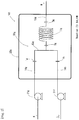
- FIG. 1 is a schematic view showing a first example of the flow reactor of the present invention, the first example having a line set assuming the above three-step reaction.
- a flow reactor 100 of FIG. 1 includes a line structure 20a for performing the first step, a line structure 20c for performing the second step, and a line structure 20e for performing the third step.
- the line structure 20c for the second step is characterized by feeding only one kind of raw material (D) (hereinafter, a line structure for feeding one kind of raw material may be referred to as an A-type line structure).
- the line structure 20a for the first step and the line structure 20e for the third step are common in that two kinds of raw materials are mixed to be allowed to react (hereinafter, a line structure for feeding a plurality of raw materials may be referred to as a B-type line structure).
- These line structures have each an appropriate configuration based on such a characteristic or commonality.
- the line structure 20c which falls under the A-type line structure, includes a single raw material feeding line 14c, reactor units 11c and 12c to react a raw material (D) fed from the raw material feeding line 14c, and a discharge line 15c to discharge a reaction product produced in the reactor units 11c and 12c.
- each of the line structures 20a and 20e which fall under the B-type line structure, includes two raw material feeding lines (14a and 14b, or 14e and 14f), reactor units (11a and 12a, or 11e and 12e) to react raw materials (A and B, or C and E) fed from the raw material feeding lines (14a and 14b, or 14e and 14f), a discharge line (15a or 15e) to discharge a reaction product produced in the reactor units (11a and 12a, or 11e and 12e), and further includes, between the raw material feeding lines (14a and 14b, or 14e and 14f) and the reactor unit (11a or 11e), a mixing unit (13a or 13e) to mix the raw materials (A and B, or C and E) fed from the raw material feeding lines (14a and 14b, or 14e and 14f) and send the mixture to the reactor unit.
- the line structures 20a, 20c, and 20e when the line structures 20a, 20c, and 20e are provided and have a relationship in which one line structure 20e uses the reaction products (discharged materials) of the other line structures 20a and 20c as raw materials, the line structures on the upstream side may also serve as raw material feeding lines for the line structure on the downstream side, and the line structure on the downstream side may also serve as a discharge line for the line structures on the upstream side.
- the line structures on the upstream side may also serve as raw material feeding lines for the line structure on the downstream side
- the line structure on the downstream side may also serve as a discharge line for the line structures on the upstream side.
- part of the line structure 20a on the upstream side also serves as the raw material feeding line 14e of the line structure 20e on the downstream side
- part of the line structure 20e on the downstream side also serves as the discharge line 15a of the line structure 20a on the upstream side.
- Each of the line structures has two or more attachable and detachable connections (hereinafter sometimes referred to as attachable and detachable parts).
- attachable and detachable parts When a plurality of line structures are included as in the illustrated example, two or more attachable and detachable parts are provided in the entire line structures.
- a section between the two attachable and detachable parts can be removed and replaced with the same or another configuration depending on the selection of two attachable and detachable parts.
- the two or more attachable and detachable parts are preferably selected so as to be a combination in which that a section between the attachable and detachable parts can be removed or replaced.
- the number of the attachable and detachable parts is not limited to two and may be three or more, or all of the joint portions may be attachable and detachable parts.
- the joint portion may be a portion of continuous piping or a welded portion.
- At least one (all in the illustrated example) of the attachable and detachable parts is accommodated in a vessel 22p. Therefore, even if leakage occurs at this connection, a leaked substance remains in the vessel 22p, and safety can be ensured.
- a fluid is accommodated in the vessel 22p, and part or all (all in the illustrated example) of the reactor units 11a, 12a, 11c, 12c, 11e and 12e are accommodated in the vessel 22p.
- the reactor units are accommodated to be capable of being in contact with the fluid, it is possible to give various functions to the fluid and improve the usefulness of the flow reactor 100.
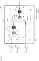
- a flow reactor 101 in FIG. 2 has a line set assuming the above the first step reaction, and thus includes a single B-type line structure 20g for two kinds of raw materials.
- the flow reactor 101 includes a single line structure composed of two raw material feeding lines 14g and 14h, a reactor unit 11g to react raw materials (K and L) fed from the raw material feeding lines 14g and 14h, a discharge line 15g to discharge a reaction product produced in the reactor unit 11g, and a mixing unit 13g to mix the raw materials (K and L) fed from the raw material feeding line 14g and 14h and send the mixture to the reactor unit 11g.
- the line structure has two or more attachable and detachable parts as a whole.
- two or more joint portions are configured as attachable and detachable parts.
- the reactor unit 11g is divided into two or more parts, it is sufficient that two or more joint portions among all the joint portions including joint portions between the parts of the reactor unit are configured as attachable and detachable parts.
- At least one (all in the illustrated example) of the attachable and detachable parts is accommodated in a vessel 22q.
- a fluid is accommodated in the vessel 22q, and part or all (all in the illustrated example) of the reactor unit 11g is accommodated in the vessel 22q.
- the combination may be selected (set) such that each line structure can be individually removed, such that part of a line structure can be removed, or such that a section across a plurality of line structures can be removed. Removal of each line structure is explained with reference to the illustrated example.
- the line structure 20a can be individually removed.
- the other B-type line structures 20e and 20g for two kinds of raw materials.
- the line structure 20c can be individually removed.
- part of a line structure can be removed.
- two or more joint portions are appropriately selected, as attachable and detachable parts, from among 2a, 2c, 2e and 2g located immediately before the reactor unit (when the reactor units are continuously arranged, portions corresponding between the parts of the reactor units are not included), 4a, 4c and 4e between the parts of the reactor units, and 3a, 3c, 3e and 3g located immediately after the reactor unit (when the reactor units are continuously arranged, portions corresponding between the parts of the reactor units are not included), any parts of the reactor units such as the first halves 11a, 11c and 11e of the reactor units, the second halves 12a, 12c and 12e of the reactor units, or all of the reactor units (11a + 12a, 11c + 12c, 11e + 12e, 11g) can be removed.
- one joint portion (for example, 4a) in the first line structure 20a, one joint portion (for example, 4c) in the second line structure 20c, and one joint portion (for example, 2e) in the third line structure 20e are configured as attachable and detachable parts.
- a combination of a joint portion (for example, a set of the joint portions 1a and 1b, or the joint portion 2a) on the upstream side of the reactor unit and a joint portion (for example, the joint portion 4a or 5p (which is also 3a or 1e)) on the downstream of the reactor unit can be mentioned.
- a joint portion for example, a set of the joint portions 1a and 1b, or the joint portion 2a
- a joint portion for example, the joint portion 4a or 5p (which is also 3a or 1e)
- a combination of a joint portion (for example, a set of the joint portions 1a and 1b) on the upstream side of the mixing unit and a joint portion (for example, the joint portion 4a or 5p (which is also 3a or 1e)) on the downstream of the reactor unit can be mentioned.
- a joint portion for example, a set of the joint portions 1a and 1b
- a joint portion for example, the joint portion 4a or 5p (which is also 3a or 1e)
- the attachable and detachable parts are accommodated in the vessel 22p, 22q, it is preferred that two or more of the attachable and detachable parts are accommodated in the vessel 22p, 22q. More preferably, the attachable and detachable parts required for removal or replacement are all accommodated in the vessel 22p, 22q.
- the attachable and detachable parts accommodated in the vessel some of the attachable and detachable parts may be in contact with the fluid in the vessel, or all of the attachable and detachable parts may be in contact with the fluid in the vessel. It is preferred that all of the attachable and detachable parts can be in contact with the fluid.
- the fluid when the fluid is a liquid, some of the attachable and detachable parts in the vessel may be immersed in the liquid, or all of the attachable and detachable parts may be immersed in the liquid. It is preferred that all of the attachable and detachable parts are immersed in the liquid.
- a form of the attachable and detachable part may be suitably selected, and examples thereof include a flange structure, a screw connection structure, and a coupler connection structure.
- a means for passing a raw material through each of the raw material feeding lines 14a, 14b, 14c, 14g, and 14h of the flow reactors as described above can be appropriately selected according to the state (liquid, gas, or dispersion) of the raw material, the stability of the raw material, and the like.
- the raw material is a liquid (including a solution)
- the reaction may be initiated based on a temperature (for example, by using a fluid to heat the reactor units 11c and 12c to a reaction initiation point or higher) or by using a reaction accelerator such as a catalyst or an initiator.
- the reaction accelerator can be placed in an appropriate position (inside the reactor) including the inner walls of the reactor units 11c and 12c.
- the number of the raw material feeding lines can be appropriately increased or decreased according to the kind of raw material and according to the mixing procedure. For example, when three raw materials are fed separately, three raw material feeding lines corresponding to the respective raw materials are used, and the three raw materials may be mixed at the same time in one mixing unit, or two of the three raw materials may be mixed in one mixing unit and then the resulting mixture may be mixed with the remaining raw material in another mixing unit.
- the raw material A is divided into two portions (raw material A1 and raw material A2), the raw material A1 and the raw material B are mixed, and then the raw material A2 may be mixed with this mixture.
- the number of raw material feeding lines is larger than the number of kinds of raw materials.
- the reactor unit may be the reactor unit 11g composed of a single part, and may be the reactor unit (11a and 12a, 11c and 12c, 11e and 12e) divided into two or more parts (two parts in the illustrated example) in the flow direction of the reaction fluid.
- the shape of the reactor unit 11a, 11c, or 11e on the upstream side may or may not be equal to the shape of the reactor unit 12a, 12c, or 12e on the downstream side.
- the inner diameter of the reactor unit on the upstream side may be smaller or larger than the inner diameter of the reactor unit on the downstream side.
- the length of the reactor unit on the upstream side may be shorter or longer than the length of the reactor unit on the downstream side.
- the shape, inner diameter, and length of the reactor unit as described above can be appropriately selected according to the reaction type and the required retention time.
- the design of the inner diameter of the reactor unit is not limited to the above example.
- the mixing efficiency improves as the inner diameter of the reactor unit decreases, and the pressure drop can reduce as the inner diameter of the reactor unit increases. Therefore, the reaction can be allowed to proceed efficiently by decreasing the inner diameter of the reactor unit on the upstream side and increasing the inner diameter of the reactor unit on the downstream side.
- a joint portion between the parts may be an attachable and detachable part that can be removed or replaced depending on a mode of use, or may be a portion of continuous piping or a welded portion.
- the joint portion as an attachable and detachable part that can be removed or replaced, it is possible to replace only an appropriate section with a new configuration.
- continuous piping or joint by welding it is possible to reduce the risk of leakage from the joint portions, resulting in safe use.
- all of the reactor unit may be capable of being in contact with the fluid in the vessel 22p, 22q, but only part of the reactor unit may be capable of being in contact with the fluid.
- the fluid is a liquid
- only part of the reactor unit may be immersed in the liquid, and the remaining part may be exposed to gas.
- each of the two or more parts of the reactor unit may be individually immersed.
- each of the reactor units 11a, 12a, 11c, 12c, 11e, 12e, and 11g is not particularly limited, and may be linear, columnar, spiral, or coiled.
- the line shape is preferably a shape with at least one bent part. This shape with at least one bent part includes a shape with at least one bent back.
- the reactor unit is preferably in a shape with an unvaried curvature like the shape of a straight line, spiral, coil, or the like.
- Non-uniformity in flow can be prevented by making the reactor unit in the shape having an unvaried curvature.
- the axial direction of the spiral or coil is not particularly limited, and may be parallel to the direction of gravity or perpendicular to the direction of gravity, but is more preferably parallel to the direction of gravity.
- a material for the reactor unit can be selected from various materials, and may be appropriately selected depending on needs for solvent resistance, pressure resistance, heat resistance, or the like.
- the reactor unit may be made of stainless steel such as SUS304, SUS316, and SUS316L, a corrosion-resistant metal such as Hastelloy and Inconel, a nonferrous metal such as titanium, copper, nickel, and aluminum, ceramics, which may be glass, (such as an inorganic sintered material), SiC, and a resin such as PEEK resin, silicone resin, and fluororesin.
- the inner diameter of the reactor unit is, for example, 0.1 mm or more, preferably 0.2 mm or more, and more preferably 0.3 mm or more, and is, for example, 50 mm or less, preferably 10 mm or less, and more preferably 5 mm or less.
- the length (entire length) of the reactor unit is preferably 1 cm or more, and more preferably 10 cm or more.
- the upper limit of the length of the reactor unit is not particularly limited, and is preferably 500 m or less, and more preferably 300 m or less.
- the length of the reactor unit may be appropriately determined according to a retention time and the like.
- the mixing unit may be equipped with a known mixer in order to sufficiently stir the raw materials.
- a known mixer examples include a T-shape mixer, a Y-shape mixer, a static mixer, a helix-type mixer, and the like.
- the number of line structures (A-type line structure, B-type line structure, and the like) constituting the flow reactor may be any of one, two, three, or four or more, and is preferably three or less.
- a fluid accommodated in the vessel 22p, 22q it is desirable to properly select a fluid accommodated in the vessel 22p, 22q to cause the fluid to provide various functions. For example, using an inert gas or a non-reactive solution as the fluid is helpful to prevent ignition, even if a highly flammable substance leaks from the connections.
- an inert gas or a non-reactive solution as the fluid is helpful to prevent ignition, even if a highly flammable substance leaks from the connections.
- a fluid whose characteristics for example, color, light scattering, pH, etc.
- a fluid such as a quench liquid for a raw material, reaction liquid, solvent, etc.
- a leaked substance a raw material, reaction liquid, solvent, etc.
- a heating medium or a cooling medium as the fluid is helpful to perform heating or heat removal at least part of the line structure by heat exchange.
- a raw material feeding line, a mixing unit, a reactor unit, a discharge line, and the like can be mentioned.
- the lower limit of the volume percentage of the part of the reactor unit to the entire reactor unit is not particularly limited, and, for example, is preferably 20% or more, more preferably 30% or more, and further preferably 40% or more.
- the upper limit of the volume percentage of the part of the reactor unit to the entire reactor unit is not particularly limited, and, for example, is preferably 90% or less, more preferably 80% or less, and further preferably 70% or less.
- the fluid is preferably a liquid, more preferably water, an aqueous solution, alcohol, or ether, and further preferably water or an aqueous solution.
- the lower limit of the amount (capacity) of the liquid with respect to the size (hereinafter referred to as a fluid accommodation size) of the vessel excluding the line structures inside the vessel is not particularly limited.
- the volume ratio of the liquid with respect to 100 volume of the fluid accommodation size is preferably 5 or more, more preferably 50 or more, and further preferably 80 or more.
- the vessel 22p and the vessel 22q may have an opening on a portion (for example, on the upper portion) of the vessel, and is preferably a closed vessel, such as a vessel with no opening or with an opening being closed, that is capable of isolating the contents from the outside.
- a closed vessel may have an outlet and an inlet, such as piping for taking in and out the fluid accommodated in the vessel.
- the size (internal capacity, etc.) of the vessel 22p or the vessel 22q is not particularly limited, and is preferably 0.05 L or more, more preferably 0.1 L or more, further preferably 0.5 L or more, and still further preferably 5 L or more.
- the upper limit of the size (internal capacity, etc.) is not particularly limited, and is preferably 1000 L or less, and more preferably 500 L or less.
- the fluid in the vessel is easily diffused, so that the uniformity of fluid characteristics can be improved, and it is possible to improve the accuracy or efficiency for detecting leakage through the fluid, for rendering a leaked substance harmless by the fluid, or for heating or cooling the reactor by the fluid. Therefore, for example, when leakage from the connections occurs, it is possible to take appropriate measures against the leakage by quickly and accurately detecting a change in the characteristics of the fluid, and higher safety can be maintained.
- the lower limit of the size (internal capacity) of the vessel 22p or the vessel 22q with respect to the total size (internal capacity) of all the line structures of the flow reactor is not particularly limited.
- the volume ratio of the internal volume of the vessel to the total internal volume of all the line structures is preferably 2 times or more, more preferably 5 times or more, and further preferably 10 times or more.
- the upper limit of the internal volume (volume ratio) of the vessel with respect to the total internal volume of all the line structures is also not particularly limited, and is preferably 5000 times or less, more preferably 2500 times or less, and further preferably 1000 times or less.
- the liquid in the line structures leaks into the vessel whose volume ratio is 5000 times or less, it is possible to detect leakage from the connections by observing a change in the characteristics (color, light scattering, pH, etc.) of the fluid in the vessel with a conventional detector and appropriate measures against the leakage can be taken.
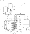
- FIG. 3 shows one example of a manufacturing facility equipped with the above flow reactor. More specifically, the manufacturing facility includes a flow reactor in which the example of FIG. 2 is more limited in that a closed vessel is adopted as the vessel 22q, in that a liquid (water in the illustrated example) is accommodated in the vessel as the fluid, and in that the entire reactor part 11g and the attachable and detachable parts 1g, 1h, 3g and 2g in the vessel are immersed in this liquid.
- the explanation of this manufacturing facility is applicable to the scope including the flow reactor of FIG. 2 and even to the scope including all flow reactors of the present invention including the flow reactor of FIG. 1 .
- the same constituents as those in FIG. 2 are given the same reference numerals, and are not described in detail.
- raw material feeding lines 14g and 14h are connected to raw material tanks 31g and 31h, respectively, and raw materials (K, L) sent out from the respective tanks are fed to the lines 14g and 14h by pumps 21g and 21h, respectively.
- the reaction product (M) is sent to a receiver tank 32 coupled to a discharge line 15g.
- a liquid 33 for quenching a reaction liquid may be placed in the receiver tank 32. By placing the liquid 33 in the receiver tank 32, safety can be further enhanced.
- the manufacturing facility of FIG. 3 includes a circulation line 36 for a fluid 30, and a heat exchanger 37 is installed on the circulation line 36. Therefore, the temperature of the fluid 30 can be controlled, and the reaction temperature in the reactor unit 11g can be controlled through the fluid 30.
- the manufacturing facility of FIG. 3 further includes a stirrer (an impeller in the illustrated example) 34 in the vessel 22q. Therefore, the uniformity of the characteristics of the fluid 30 can be improved, and it is possible to improve the accuracy or efficiency for detecting leakage through the fluid, for rendering a leaked substance harmless by the fluid, or for heating or cooling the reactor by the fluid.
- a stirrer an impeller in the illustrated example
- the pH of the fluid (water in the illustrated example) 30 becomes higher or lower when leakage occurs. By monitoring a value displayed on a pH meter 35 inserted into the vessel 22q, the presence or absence of leakage can be detected.
- stirrer a known means such as a fluid jet means can be employed in addition to the impeller as required.
- the change in the characteristics includes not only a pH change but also a color change and a light scattering change as described above.
- an appropriate observation means such as a chromaticity meter, a scattered light measurement device, and a turbidimeter may be attached to a window through which the characteristics of the fluid in the vessel 22q can be observed.
- the position at which a sensor, such as a pH meter or a chromaticity meter, that reads the characteristics of the fluid is attached is not particularly limited as long as the characteristics of the fluid can be observed.
- the sensor may be attached at any place in the vessel 22q where the characteristics of the fluid can be observed, or at any place where the characteristics of the fluid 30 taken out from the vessel 22q by an appropriate means such as a fluid outlet valve, a circulation means, and a sampling port can be observed.
- a signal may be transmitted to an alarm generator, the raw material feeding pumps 21g and 21h, or raw material feeding control valves 38g and 38h installed on the raw material feeding lines, whereby an alarm can be raised, or the feeding of the raw materials can be stopped.
- the new configuration refers to a configuration including one or more selected from line structure components including a raw material feeding line, a mixing unit, a reactor unit, and a discharge line.
- the new configuration to be attached may be part of the line structure (for example, a feeding line only, a mixing unit only, a reactor unit only, a discharge line only, or an appropriate combination thereof), or may be a combination of one or more line structures and part of another line structure (for example, a configuration formed of one line structure composed of a feeding line, a mixing unit, a reactor unit, and a discharge line, and a reactor unit connected to such a line structure).
- the new configuration may be the same as or different from the configuration of the section before replacement. When the configurations before and after replacement are the same, the flow reactor can be refreshed without changing the reaction mode. When the configurations before and after replacement are different, the reaction mode can be changed as appropriate.
- the line is disconnected at the connections 2c and 5q before and after the reactor unit to remove the reactor units 11c and 12c, and a new raw material feeding line 14i is installed to form another flow reactor 102 as shown in FIG. 4 .
- the line is disconnected at the connections 2g and 3g before and after the reactor unit to remove the reactor unit 11g, and a new reactor unit 11h with an inner diameter different from the inner diameter of the former reactor unit 11g is installed to form another flow reactor 103 as shown in FIG. 5 .
- the timing for replacement with the new configuration can be set as appropriate.
- replacement with the new configuration may be performed at the timing of changing a raw material. More specifically, it is preferred to stop a flow stream from the raw material to the reaction product and start the flow stream after replacing with the new configuration and changing the raw material.
- the timing of changing the raw material includes the timing of switching a production item, the timing of changing a raw material lot, and the timing of switching from one small unit to another small unit when a raw material lot is divided into small units.
- the timing of replacement with the new configuration may be at the time of the outage of the manufacturing facility (such as the time of shutdown of a plant), at the time of routine check of the manufacturing facility, at the time of parts replacement of the manufacturing facility, or the like.
- a reaction using the above flow reactor is not particularly limited.
- a raw material to be fed may be a gas or a liquid, and a liquid raw material is often used.
- the flow reactor is preferably used to react a solution containing a compound having an SH group, an OH group, an NH 2 group, or an NHR group (where R represents an organic group) with a solution containing an activated carbonyl compound such as phosgene or triphosgene.
- the NH 2 group reacts with phosgene or triphosgene to be isocyanated.
- a compound having two or more of the SH group, the OH group, the NHR group, and the like is used as a raw material to allow to react with phosgene, triphosgene, or the like, a compound can be formed in which a hydrogen atom is removed from each of two groups selected from the SH group, the OH group, the NHR group, and the like, and the groups are linked via a carbonyl group.
- triphosgene When triphosgene is used, it is preferred to also use an amine as a raw material.
- the use of an amine allows triphosgene to quickly change to phosgene, and the reaction with a compound having an SH group, an OH group, an NH 2 group, or an NHR group (where R represents an organic group) can be accelerated.
- the three raw materials may be fed from separate raw material feeding lines, mixed in a single mixing unit, and then reacted in the reactor unit; or a mixture obtained by mixing the two raw materials in advance may be fed from a raw material feeding line, the remaining raw material may be fed from another raw material feeding line, and both may be mixed in the mixing unit and then reacted in the reactor unit.
Landscapes
- Chemical & Material Sciences (AREA)
- Organic Chemistry (AREA)
- Chemical Kinetics & Catalysis (AREA)
- Physical Or Chemical Processes And Apparatus (AREA)
- Organic Low-Molecular-Weight Compounds And Preparation Thereof (AREA)
Abstract
Description
- The present invention relates to a flow reactor.
- A micro-flow reactor is a chemical reaction apparatus generally utilizing a microchannel in the order of submillimeter as a reaction field. The micro-flow reactor has attracted attention in recent years because it has specific effects, due to the micro reaction field, such as high-speed mixing performance (for example, when two liquids are mixed in a micro-space, the substance diffusion distance in the two liquids decreases, resulting in shortening the time of mass transfer movement), heat removal efficiency (since the reaction field is small, thermal efficiency is extremely high and temperature control is easy), reaction control performance, interface control performance, or the like. In addition, it is expected that the technology of the micro-flow reactor provides various effects such as improved safety and significantly reduced cost of equipment along with downsizing of the whole process, process intensification (micro in macro) by incorporating into existing processes, and production of substances that could not be produced by an existing production method.
- The micro-flow reactor has a problem that only a limited amount can be processed at a time. Therefore, process development of a flow reactor which can be practically used even if a processing amount increases is being carried out. The flow reactor is a chemical reaction apparatus in which the diameter of a flow channel is enlarged to the order of millimeters to centimeters to the extent that the characteristics of the micro-flow reactor are not impaired to enhance the operability. The flow reactor is mainly composed of a raw material feeding line, a reaction unit, and an operation control unit (such as, for example, Patent Document 1).
- Patent Document 1:
JP 2013-543021 (A - However, the flow reactor is configured with a plurality of lines connected to each other, and there is a concern that leakage may occur at the connections of the lines. If leakage occurs, the leakage continues until a liquid-feeding stop signal is transmitted to an operation controller, resulting in polluting the surrounding environment. In particular, if a leaked substance is a dangerous substance, the damage to the surroundings increases.
- The present invention has been made by focusing on the above situation, and an object of the present invention is to provide a flow reactor that can ensure safety even if leakage occurs at the connections of the lines.
- As a result of intensive studies for achieving the above object, the inventors have found that when a connection of the lines is accommodated in a vessel in which a reactor unit and a fluid are accommodated to be capable of being in contact with each other, even if leakage occurs at the connection of the lines, the leaked substance remains in the vessel and can be appropriately handled by using the fluid in the vessel, so that safety can be ensured, and completed the present invention accordingly.
- That is, the present invention is as follows:
- [1] A flow reactor comprising one or more line structures, each of the line structures comprising a raw material feeding line, a reactor unit to react a raw material fed from the raw material feeding line, and a discharge line to discharge a reaction product produced in the reactor unit,
wherein the flow reactor comprises a vessel in which part or all of the reactor unit and a fluid are accommodated to be capable of being in contact with each other,
wherein each of the line structures comprises two or more attachable and detachable connections, and
wherein at least one of the attachable and detachable connections is accommodated in the vessel. - [2] The flow reactor according to [1], wherein at least one of the line structures comprises two or more raw material feeding lines, and further comprises, between the raw material feeding lines and the reactor unit, a mixing unit to mix raw materials fed from the two or more raw material feeding lines and send a mixture to the reactor unit.
- [3] The flow reactor according to [1] or [2], wherein the attachable and detachable connections are arranged on an upstream side of the reactor unit and a downstream side of the reactor unit in each of the line structures.
- [4] The flow reactor according to [2], wherein the attachable and detachable connections are arranged on an upstream side of the mixing unit and a downstream side of the reactor unit in each of the line structures.
- [5] The flow reactor according to any of [1] to [4], wherein two or more of the attachable and detachable connections are accommodated in the vessel.
- [6] The flow reactor according to any of [1] to [5], wherein the fluid is a liquid and is capable either of quenching a leaked substance from the line structures, of having a characteristic changeable when contacting the leaked substance, of being heat-exchanged with at least part of the line structures, or of supporting the reactor unit.
- [7] The flow reactor according to [6], wherein the vessel accommodate a liquid as the fluid, the space where there isn't the liquid is filled with a gas, and one or more part of the reactor unit is exposed to the gas portion without contacting the liquid.
- [8] The flow reactor according to any of [1] to [7], wherein the vessel is a closed vessel capable of isolating contents of the vessel from outside.
- [9] The flow reactor according to any of [1] to [8], wherein the reactor unit has a flow channel with an inner diameter of 0.1 mm or more and 50 mm or less.
- [10] The flow reactor according to any of [1] to [9], wherein the reactor unit has a shape with at least one bent part.
- [11] A manufacturing facility comprising the flow reactor according to any of [1] to [10].
- [12] The manufacturing facility according to [11], wherein the fluid accommodated in the vessel of the flow reactor is a medium whose characteristic is changeable when contacting a reaction liquid, and the manufacturing facility comprises a sensor capable of detecting the change of the characteristic.
- [13] A method for using the manufacturing facility according to [11] or [12], the method comprising: when a raw material is fed to the manufacturing facility to obtain a reaction product,
selecting two or more of the attachable and detachable connections to remove a section between the two or more connections, and
replacing with a new configuration comprising one or more selected from line structure components including a raw material feeding line, a mixing unit, a reactor unit, and a discharge line. - [14] The method according to [13] comprising:
- stopping a flow stream from the raw material to the reaction product, and
- after replacing the section between the connections and changing the raw material, starting the flow stream.
- [15] The method according to [13] comprising:
- stopping a flow stream from the raw material to the reaction product, and
- after replacing the section between the connections and performing one or more selected from an outage, routine check, and one or more parts replacement of the manufacturing facility, starting the flow stream.
- According to the present invention, the connection of the lines is accommodated in the vessel in which the reactor unit and the fluid are accommodated to be capable of being in contact with each other, and even if leakage occurs at this connection of the lines, a leaked substance remains in the vessel, so that safety can be ensured.
-
-
FIG. 1 is a schematic view showing one example of a flow reactor of the present invention. -
FIG. 2 is a schematic view showing another example of a flow reactor of the present invention. -
FIG. 3 is a schematic view showing one example of a manufacturing facility using a flow reactor of the present invention. -
FIG. 4 is a schematic view of a flow reactor for explaining one example of a method for using a manufacturing facility of the present invention. -
FIG. 5 is a schematic view of a flow reactor for explaining another example of a method for using a manufacturing facility of the present invention. - As for the entire line set of a flow reactor, there are an infinite number of variations depending on a reaction mode to be performed. Hereinafter, the present invention will be illustrated and described with reference to representative examples. However, the present invention is not intended to be limited to examples illustrated and described below and can also be carried out with appropriate modifications within the scope of the invention, and such modifications are included in the technical scope of the invention.
-
- [First step: Compound A + Compound B → Compound C];
- [Second step: Compound D → Compound E]; and
- [Third step: Compound C + Compound E → Compound F]
-
FIG. 1 is a schematic view showing a first example of the flow reactor of the present invention, the first example having a line set assuming the above three-step reaction. - Specifically, a
flow reactor 100 ofFIG. 1 includes aline structure 20a for performing the first step, aline structure 20c for performing the second step, and aline structure 20e for performing the third step. Theline structure 20c for the second step is characterized by feeding only one kind of raw material (D) (hereinafter, a line structure for feeding one kind of raw material may be referred to as an A-type line structure). Theline structure 20a for the first step and theline structure 20e for the third step are common in that two kinds of raw materials are mixed to be allowed to react (hereinafter, a line structure for feeding a plurality of raw materials may be referred to as a B-type line structure). These line structures have each an appropriate configuration based on such a characteristic or commonality. Specifically, theline structure 20c, which falls under the A-type line structure, includes a single rawmaterial feeding line 14c,reactor units material feeding line 14c, and adischarge line 15c to discharge a reaction product produced in thereactor units line structures - As in the example of
FIG. 1 , when theline structures line structure 20e uses the reaction products (discharged materials) of theother line structures FIG. 1 , part of theline structure 20a on the upstream side (specifically, the downstream part of thereactor unit 12a) also serves as the rawmaterial feeding line 14e of theline structure 20e on the downstream side, and part of theline structure 20e on the downstream side (specifically, the upstream part of the rawmaterial mixing unit 13e) also serves as thedischarge line 15a of theline structure 20a on the upstream side. The same relationship applied to the relationship between theline structure 20c and theline structure 20e. - Each of the line structures has two or more attachable and detachable connections (hereinafter sometimes referred to as attachable and detachable parts). When a plurality of line structures are included as in the illustrated example, two or more attachable and detachable parts are provided in the entire line structures. Specifically, among
joint portions material feeding lines units joint portions units material feeding line 14c and thereactor units joint portions reactor units discharge lines joint portions parts joint portions - In the present invention, at least one (all in the illustrated example) of the attachable and detachable parts is accommodated in a
vessel 22p. Therefore, even if leakage occurs at this connection, a leaked substance remains in thevessel 22p, and safety can be ensured. - Furthermore, in the present invention, a fluid is accommodated in the
vessel 22p, and part or all (all in the illustrated example) of thereactor units vessel 22p. When the fluid is accommodated in the vessel, and the reactor units are accommodated to be capable of being in contact with the fluid, it is possible to give various functions to the fluid and improve the usefulness of theflow reactor 100. - The basic concept of the flow reactor shown in the first example is the same even if the assumption reaction, that is, the entire line set changes. A
flow reactor 101 inFIG. 2 has a line set assuming the above the first step reaction, and thus includes a single B-type line structure 20g for two kinds of raw materials. Specifically, theflow reactor 101 includes a single line structure composed of two rawmaterial feeding lines reactor unit 11g to react raw materials (K and L) fed from the rawmaterial feeding lines discharge line 15g to discharge a reaction product produced in thereactor unit 11g, and amixing unit 13g to mix the raw materials (K and L) fed from the rawmaterial feeding line reactor unit 11g. - In the example of
FIG. 2 as well, the line structure has two or more attachable and detachable parts as a whole. Specifically, amongjoint portions material feeding lines mixing unit 13g; ajoint portion 2g of themixing unit 13g and thereactor unit 11g; and ajoint portion 3g of thereactor unit 11g and thedischarge line 15g, two or more joint portions are configured as attachable and detachable parts. When thereactor unit 11g is divided into two or more parts, it is sufficient that two or more joint portions among all the joint portions including joint portions between the parts of the reactor unit are configured as attachable and detachable parts. - In addition, in the example of
FIG. 2 as well, at least one (all in the illustrated example) of the attachable and detachable parts is accommodated in avessel 22q. Furthermore, in the example ofFIG. 2 as well, a fluid is accommodated in thevessel 22q, and part or all (all in the illustrated example) of thereactor unit 11g is accommodated in thevessel 22q. - In the flow reactor of the present invention including the examples of
FIG. 1 andFIG. 2 , it is recommended to appropriately select (set) a combination of attachable and detachable parts from the above-described joint portions so that a section between the attachable and detachable parts can be removed and replaced with another configuration. For example, in the selection (setting) of a combination of the attachable and detachable parts, the combination may be selected (set) such that each line structure can be individually removed, such that part of a line structure can be removed, or such that a section across a plurality of line structures can be removed. Removal of each line structure is explained with reference to the illustrated example. For example, when thejoint portions unit 13a and the rawmaterial feeding lines joint portion 3a between thereactor unit 12a and thedischarge line 15a are configured as attachable and detachable parts, theline structure 20a can be individually removed. The same applies to the other B-type line structures A-type line structure 20c having a single raw material feeding line, if thejoint portion 2c between the rawmaterial feeding line 14c and thereactor unit 11c and thejoint portion 3c between thereactor unit 12c and thedischarge line 15c are configured as attachable and detachable parts, theline structure 20c can be individually removed. - An example in which part of a line structure can be removed is explained with reference to the illustrated example. When two or more joint portions are appropriately selected, as attachable and detachable parts, from among 2a, 2c, 2e and 2g located immediately before the reactor unit (when the reactor units are continuously arranged, portions corresponding between the parts of the reactor units are not included), 4a, 4c and 4e between the parts of the reactor units, and 3a, 3c, 3e and 3g located immediately after the reactor unit (when the reactor units are continuously arranged, portions corresponding between the parts of the reactor units are not included), any parts of the reactor units such as the
first halves second halves - There are many examples in which a section across line structures can be removed. One example thereof is such that one joint portion (for example, 4a) in the
first line structure 20a, one joint portion (for example, 4c) in thesecond line structure 20c, and one joint portion (for example, 2e) in thethird line structure 20e are configured as attachable and detachable parts. - As one example of a preferable combination of the attachable and detachable parts, in the case of assuming removal of a specific reactor unit (for example, 11a), a combination of a joint portion (for example, a set of the
joint portions joint portion 2a) on the upstream side of the reactor unit and a joint portion (for example, thejoint portion FIG. 2 is a combination of a set of thejoint portions joint portion 2g, and thejoint portion 3g. - As another example of a preferable combination of the attachable and detachable parts, in the case of assuming removal of a specific reactor unit (for example, 11a) together with a mixing unit (for example, 13a), a combination of a joint portion (for example, a set of the
joint portions joint portion FIG. 2 is a combination of a set of thejoint portions joint portion 3g. - Although it is sufficient that at least one of the attachable and detachable parts is accommodated in the
vessel vessel vessel - A form of the attachable and detachable part may be suitably selected, and examples thereof include a flange structure, a screw connection structure, and a coupler connection structure.
- A means for passing a raw material through each of the raw
material feeding lines pumps - In the
A-type line structure 20c having a single raw material feeding line, the reaction may be initiated based on a temperature (for example, by using a fluid to heat thereactor units reactor units - In the B-
type line structures - The reactor unit may be the
reactor unit 11g composed of a single part, and may be the reactor unit (11a and 12a, 11c and 12c, 11e and 12e) divided into two or more parts (two parts in the illustrated example) in the flow direction of the reaction fluid. In the case of the reactor unit divided into two or more parts, the shape of thereactor unit reactor unit - In the case of the reactor unit divided into two or more parts, a joint portion between the parts may be an attachable and detachable part that can be removed or replaced depending on a mode of use, or may be a portion of continuous piping or a welded portion. For example, by forming the joint portion as an attachable and detachable part that can be removed or replaced, it is possible to replace only an appropriate section with a new configuration. Moreover, by using continuous piping or joint by welding, it is possible to reduce the risk of leakage from the joint portions, resulting in safe use.
- As described above, all of the reactor unit may be capable of being in contact with the fluid in the
vessel - The line shape of each of the
reactor units - A material for the reactor unit can be selected from various materials, and may be appropriately selected depending on needs for solvent resistance, pressure resistance, heat resistance, or the like. For example, the reactor unit may be made of stainless steel such as SUS304, SUS316, and SUS316L, a corrosion-resistant metal such as Hastelloy and Inconel, a nonferrous metal such as titanium, copper, nickel, and aluminum, ceramics, which may be glass, (such as an inorganic sintered material), SiC, and a resin such as PEEK resin, silicone resin, and fluororesin.
- The inner diameter of the reactor unit is, for example, 0.1 mm or more, preferably 0.2 mm or more, and more preferably 0.3 mm or more, and is, for example, 50 mm or less, preferably 10 mm or less, and more preferably 5 mm or less.
- The length (entire length) of the reactor unit is preferably 1 cm or more, and more preferably 10 cm or more. The upper limit of the length of the reactor unit is not particularly limited, and is preferably 500 m or less, and more preferably 300 m or less. The length of the reactor unit may be appropriately determined according to a retention time and the like.
- The mixing unit may be equipped with a known mixer in order to sufficiently stir the raw materials. Examples of such a mixer include a T-shape mixer, a Y-shape mixer, a static mixer, a helix-type mixer, and the like.
- The number of line structures (A-type line structure, B-type line structure, and the like) constituting the flow reactor may be any of one, two, three, or four or more, and is preferably three or less.
- In the flow reactor of the present invention, it is desirable to properly select a fluid accommodated in the
vessel line structures - When the fluid is a liquid, the lower limit of the amount (capacity) of the liquid with respect to the size (hereinafter referred to as a fluid accommodation size) of the vessel excluding the line structures inside the vessel is not particularly limited. For example, the volume ratio of the liquid with respect to 100 volume of the fluid accommodation size is preferably 5 or more, more preferably 50 or more, and further preferably 80 or more. The presence of the fluid in a sufficient amount with respect to the amount of a liquid leaking from the line structures into the vessel makes it possible to improve the accuracy or efficiency for rendering a leaked substance harmless by the fluid or for heating or cooling the reactor by the fluid.
- The
vessel 22p and thevessel 22q may have an opening on a portion (for example, on the upper portion) of the vessel, and is preferably a closed vessel, such as a vessel with no opening or with an opening being closed, that is capable of isolating the contents from the outside. Such a closed vessel may have an outlet and an inlet, such as piping for taking in and out the fluid accommodated in the vessel. - The size (internal capacity, etc.) of the
vessel 22p or thevessel 22q is not particularly limited, and is preferably 0.05 L or more, more preferably 0.1 L or more, further preferably 0.5 L or more, and still further preferably 5 L or more. The upper limit of the size (internal capacity, etc.) is not particularly limited, and is preferably 1000 L or less, and more preferably 500 L or less. By thus adjusting the size of the vessel, it becomes easy to install a device to detect a change in the characteristics of the fluid in the vessel in the event of leakage. In addition, when the size of the vessel is 1000 L or less, the fluid in the vessel is easily diffused, so that the uniformity of fluid characteristics can be improved, and it is possible to improve the accuracy or efficiency for detecting leakage through the fluid, for rendering a leaked substance harmless by the fluid, or for heating or cooling the reactor by the fluid. Therefore, for example, when leakage from the connections occurs, it is possible to take appropriate measures against the leakage by quickly and accurately detecting a change in the characteristics of the fluid, and higher safety can be maintained. - The lower limit of the size (internal capacity) of the
vessel 22p or thevessel 22q with respect to the total size (internal capacity) of all the line structures of the flow reactor is not particularly limited. The volume ratio of the internal volume of the vessel to the total internal volume of all the line structures is preferably 2 times or more, more preferably 5 times or more, and further preferably 10 times or more. By thus adjusting the internal volume of the vessel to be larger than the total internal volume of all the line structures, when the liquid in the line structures leaks into the vessel, it is possible to keep the leaked liquid inside the vessel and effectively suppress leakage to the outside of the vessel. The presence of the fluid in a sufficient amount with respect to the amount of a liquid leaking from the line structures into the vessel makes it possible to improve the accuracy or efficiency for rendering a leaked substance harmless by the fluid or for heating or cooling the reactor by the fluid. - The upper limit of the internal volume (volume ratio) of the vessel with respect to the total internal volume of all the line structures is also not particularly limited, and is preferably 5000 times or less, more preferably 2500 times or less, and further preferably 1000 times or less. When the liquid in the line structures leaks into the vessel whose volume ratio is 5000 times or less, it is possible to detect leakage from the connections by observing a change in the characteristics (color, light scattering, pH, etc.) of the fluid in the vessel with a conventional detector and appropriate measures against the leakage can be taken.
-
FIG. 3 shows one example of a manufacturing facility equipped with the above flow reactor. More specifically, the manufacturing facility includes a flow reactor in which the example ofFIG. 2 is more limited in that a closed vessel is adopted as thevessel 22q, in that a liquid (water in the illustrated example) is accommodated in the vessel as the fluid, and in that theentire reactor part 11g and the attachable anddetachable parts FIG. 2 and even to the scope including all flow reactors of the present invention including the flow reactor ofFIG. 1 . In the explanation of the example ofFIG. 3 , the same constituents as those inFIG. 2 are given the same reference numerals, and are not described in detail. - In the
manufacturing facility 200 ofFIG. 3 , rawmaterial feeding lines raw material tanks lines pumps receiver tank 32 coupled to adischarge line 15g. Depending on the type of reaction, a liquid 33 for quenching a reaction liquid may be placed in thereceiver tank 32. By placing the liquid 33 in thereceiver tank 32, safety can be further enhanced. - The manufacturing facility of
FIG. 3 includes acirculation line 36 for a fluid 30, and aheat exchanger 37 is installed on thecirculation line 36. Therefore, the temperature of the fluid 30 can be controlled, and the reaction temperature in thereactor unit 11g can be controlled through the fluid 30. - The manufacturing facility of
FIG. 3 further includes a stirrer (an impeller in the illustrated example) 34 in thevessel 22q. Therefore, the uniformity of the characteristics of the fluid 30 can be improved, and it is possible to improve the accuracy or efficiency for detecting leakage through the fluid, for rendering a leaked substance harmless by the fluid, or for heating or cooling the reactor by the fluid. In particular, in the example ofFIG. 3 , it is assumed that the pH of the fluid (water in the illustrated example) 30 becomes higher or lower when leakage occurs. By monitoring a value displayed on apH meter 35 inserted into thevessel 22q, the presence or absence of leakage can be detected. - As the stirrer, a known means such as a fluid jet means can be employed in addition to the impeller as required.
- When leakage is detected through a change in the characteristics of the fluid, the change in the characteristics includes not only a pH change but also a color change and a light scattering change as described above. When leakage is detected through a color change, a light scattering change, or the like, an appropriate observation means (sensor) such as a chromaticity meter, a scattered light measurement device, and a turbidimeter may be attached to a window through which the characteristics of the fluid in the
vessel 22q can be observed. - The position at which a sensor, such as a pH meter or a chromaticity meter, that reads the characteristics of the fluid is attached is not particularly limited as long as the characteristics of the fluid can be observed. For example, the sensor may be attached at any place in the
vessel 22q where the characteristics of the fluid can be observed, or at any place where the characteristics of the fluid 30 taken out from thevessel 22q by an appropriate means such as a fluid outlet valve, a circulation means, and a sampling port can be observed. - When leakage is detected, a signal may be transmitted to an alarm generator, the raw material feeding pumps 21g and 21h, or raw material
feeding control valves - In each of the
flow reactors - There are many examples in which the configurations before and after replacement are different, and some of these examples are illustrated. In the
flow reactor 100 ofFIG. 1 , the line is disconnected at theconnections reactor units flow reactor 102 as shown inFIG. 4 . In theflow type reactor 101 ofFIG. 2 , the line is disconnected at theconnections reactor unit 11g, and anew reactor unit 11h with an inner diameter different from the inner diameter of theformer reactor unit 11g is installed to form anotherflow reactor 103 as shown inFIG. 5 . - The timing for replacement with the new configuration can be set as appropriate. For example, replacement with the new configuration may be performed at the timing of changing a raw material. More specifically, it is preferred to stop a flow stream from the raw material to the reaction product and start the flow stream after replacing with the new configuration and changing the raw material. The timing of changing the raw material includes the timing of switching a production item, the timing of changing a raw material lot, and the timing of switching from one small unit to another small unit when a raw material lot is divided into small units.
- The timing of replacement with the new configuration may be at the time of the outage of the manufacturing facility (such as the time of shutdown of a plant), at the time of routine check of the manufacturing facility, at the time of parts replacement of the manufacturing facility, or the like.
- A reaction using the above flow reactor is not particularly limited. A raw material to be fed may be a gas or a liquid, and a liquid raw material is often used. When a liquid raw material is used, for example, the flow reactor is preferably used to react a solution containing a compound having an SH group, an OH group, an NH2 group, or an NHR group (where R represents an organic group) with a solution containing an activated carbonyl compound such as phosgene or triphosgene. The SH group, the OH group, or the NHR group reacts with phosgene or triphosgene, and a compound in which ClC(=O)-group is bonded instead of a hydrogen atom in the SH group, the OH group, or the NHR group is formed. The NH2 group reacts with phosgene or triphosgene to be isocyanated. When a compound having two or more of the SH group, the OH group, the NHR group, and the like is used as a raw material to allow to react with phosgene, triphosgene, or the like, a compound can be formed in which a hydrogen atom is removed from each of two groups selected from the SH group, the OH group, the NHR group, and the like, and the groups are linked via a carbonyl group. In such a reaction, even if the raw material liquid or the reaction liquid containing phosgene, triphosgene, or the like leaks from the connections, the leaked substance can be kept in the vessel by using the flow reactor of the present invention, so that safety can be maintained. In addition, if water or an aqueous solution is used as a fluid to be accommodated in the vessel, phosgene, triphosgene, and the reaction liquid leaking from the connections can be quenched, so that safety can be maintained. Furthermore, by observing the pH of water or the aqueous solution, the leakage of the raw material liquid or the reaction liquid can also be detected.
- When triphosgene is used, it is preferred to also use an amine as a raw material. The use of an amine allows triphosgene to quickly change to phosgene, and the reaction with a compound having an SH group, an OH group, an NH2 group, or an NHR group (where R represents an organic group) can be accelerated.
- When a compound having an SH group, an OH group, an NH2 group, or an NHR group (wherein R represents an organic group), triphosgene, and an amine are used as raw materials, the three raw materials may be fed from separate raw material feeding lines, mixed in a single mixing unit, and then reacted in the reactor unit; or a mixture obtained by mixing the two raw materials in advance may be fed from a raw material feeding line, the remaining raw material may be fed from another raw material feeding line, and both may be mixed in the mixing unit and then reacted in the reactor unit.
- The present application claims priority based on Japanese Patent Application No.
2017-148083 filed on July 31, 2017 2017-148083 filed on July 31, 2017 -
- 200: manufacturing facility
- 100, 101, 102, 103: flow reactor
- 22p, 22q: vessel
- 20a, 20c, 20e, 20g: line structure
- 14a, 14b, 14c, 14e, 14f, 14g, 14h, 14i: raw material feeding line
- 13a, 13e, 13g: mixing unit
- 11a, 12a, 11c, 12c, 11e, 12e, 11g: reactor unit
- 15a, 15c, 15e, 15g: discharge line
- 1a, 1b, 1e, 1f, 1g, 1h, 2a, 2c, 2e, 2g, 3a, 3c, 3e, 3g, 4a, 4c, 4e, 5p, 5q: joint portion (attachable and detachable connection)
- 30: fluid
Claims (15)
- A flow reactor comprising one or more line structures, each of the line structures comprising a raw material feeding line, a reactor unit to react a raw material fed from the raw material feeding line, and a discharge line to discharge a reaction product produced in the reactor unit,
wherein the flow reactor comprises a vessel in which part or all of the reactor unit and a fluid are accommodated to be capable of being in contact with each other,
wherein each of the line structures comprises two or more attachable and detachable connections, and
wherein at least one of the attachable and detachable connections is accommodated in the vessel. - The flow reactor according to claim 1, wherein at least one of the line structures comprises two or more raw material feeding lines, and further comprises, between the raw material feeding lines and the reactor unit, a mixing unit to mix raw materials fed from the two or more raw material feeding lines and send a mixture to the reactor unit.
- The flow reactor according to claim 1 or 2, wherein the attachable and detachable connections are arranged on an upstream side of the reactor unit and a downstream side of the reactor unit in each of the line structures.
- The flow reactor according to claim 2, wherein the attachable and detachable connections are arranged on an upstream side of the mixing unit and a downstream side of the reactor unit in each of the line structures.
- The flow reactor according to any of claims 1 to 4, wherein two or more of the attachable and detachable connections are accommodated in the vessel.
- The flow reactor according to any of claims 1 to 5, wherein the fluid is a liquid and is capable either of quenching a leaked substance from the line structures, of having a characteristic changeable when contacting the leaked substance, of being heat-exchanged with at least part of the line structures, or of supporting the reactor unit.
- The flow reactor according to claim 6, wherein the vessel accommodate a liquid as the fluid, the space where there isn't the liquid is filled with a gas, and one or more part of the reactor unit is exposed to the gas portion without contacting the liquid.
- The flow reactor according to any of claims 1 to 7, wherein the vessel is a closed vessel capable of isolating contents of the vessel from outside.
- The flow reactor according to any of claims 1 to 8, wherein the reactor unit has a flow channel with an inner diameter of 0.1 mm or more and 50 mm or less.
- The flow reactor according to any of claims 1 to 9, wherein the reactor unit has a shape with at least one bent part.
- A manufacturing facility comprising the flow reactor according to any of claims 1 to 10.
- The manufacturing facility according to claim 11, wherein the fluid accommodated in the vessel of the flow reactor is a medium whose characteristic is changeable when contacting a reaction liquid, and the manufacturing facility comprises a sensor capable of detecting the change of the characteristic.
- A method for using the manufacturing facility according to claim 11 or 12, the method comprising: when a raw material is fed to the manufacturing facility to obtain a reaction product,
selecting two or more of the attachable and detachable connections to remove a section between the two or more connections, and
replacing with a new configuration comprising one or more selected from line structure components including a raw material feeding line, a mixing unit, a reactor unit, and a discharge line. - The method according to claim 13 comprising:stopping a flow stream from the raw material to the reaction product, andafter replacing the section between the connections and changing the raw material, starting the flow stream.
- The method according to claim 13 comprising:stopping a flow stream from the raw material to the reaction product, andafter replacing the section between the connections and performing one or more selected from an outage, routine check, and one or more parts replacement of the manufacturing facility, starting the flow stream.
Applications Claiming Priority (2)
| Application Number | Priority Date | Filing Date | Title |
|---|---|---|---|
| JP2017148083 | 2017-07-31 | ||
| PCT/JP2018/022063 WO2019026425A1 (en) | 2017-07-31 | 2018-06-08 | Flow reactor |
Publications (2)
| Publication Number | Publication Date |
|---|---|
| EP3662994A1 true EP3662994A1 (en) | 2020-06-10 |
| EP3662994A4 EP3662994A4 (en) | 2021-03-17 |
Family
ID=65233620
Family Applications (1)
| Application Number | Title | Priority Date | Filing Date |
|---|---|---|---|
| EP18841200.1A Withdrawn EP3662994A4 (en) | 2017-07-31 | 2018-06-08 | Flow reactor |
Country Status (4)
| Country | Link |
|---|---|
| US (1) | US11071965B2 (en) |
| EP (1) | EP3662994A4 (en) |
| JP (1) | JPWO2019026425A1 (en) |
| WO (1) | WO2019026425A1 (en) |
Cited By (1)
| Publication number | Priority date | Publication date | Assignee | Title |
|---|---|---|---|---|
| CN116586002A (en) * | 2023-05-17 | 2023-08-15 | 武汉中能恒信工程技术有限公司 | System and method for preparing vinyl sulfate by oxidizing vinyl sulfite with ozone |
Families Citing this family (4)
| Publication number | Priority date | Publication date | Assignee | Title |
|---|---|---|---|---|
| US11931716B2 (en) | 2019-03-20 | 2024-03-19 | Kaneka Corporation | Reaction apparatus |
| JP7718988B2 (en) * | 2019-12-26 | 2025-08-05 | 株式会社カネカ | Flow Reactor |
| CN115334883B (en) * | 2020-03-09 | 2024-11-29 | 凯米拉公司 | Performic acid production system and method |
| JP2025011636A (en) * | 2023-07-11 | 2025-01-24 | 横河電機株式会社 | Apparatus, method, and program |
Family Cites Families (10)
| Publication number | Priority date | Publication date | Assignee | Title |
|---|---|---|---|---|
| JP2008023406A (en) * | 2006-07-18 | 2008-02-07 | Fuji Xerox Co Ltd | Microreactor comprising an integrated connecting member |
| CA2666413C (en) | 2006-10-18 | 2016-08-02 | Mitsubishi Gas Chemical Company, Inc. | Method for producing peroxymonosulfuric acid and apparatus for continuously producing peroxymonosulfuric acid |
| JP5365232B2 (en) * | 2009-02-06 | 2013-12-11 | 和光純薬工業株式会社 | Method for producing vinyl-substituted aryl compound using microreactor |
| WO2012037596A1 (en) | 2010-09-22 | 2012-03-29 | Commonwealth Scientific And Industrial Research Organisation | Continuous flow polymerisation process |
| JP2012140421A (en) * | 2010-12-16 | 2012-07-26 | Koei Chem Co Ltd | Method of producing organic metal compound |
| EP2766111B1 (en) * | 2011-10-14 | 2018-08-01 | Council of Scientific & Industrial Research | Continuous modular reactor |
| JP2014023982A (en) * | 2012-07-25 | 2014-02-06 | Tokyo Institute Of Technology | Microreactor device and microchannel |
| AU2015320349B2 (en) | 2014-09-25 | 2020-03-12 | Bausch + Lomb Ireland Limited | Continuous flow carboxylation reaction |
| US9481764B1 (en) * | 2015-10-13 | 2016-11-01 | The Boeing Company | Flow reactor synthesis of polymers |
| JP2017148083A (en) | 2016-02-22 | 2017-08-31 | テクノエレメント株式会社 | Potential therapeutic instrument and control method of the same |
-
2018
- 2018-06-08 EP EP18841200.1A patent/EP3662994A4/en not_active Withdrawn
- 2018-06-08 JP JP2019533937A patent/JPWO2019026425A1/en active Pending
- 2018-06-08 WO PCT/JP2018/022063 patent/WO2019026425A1/en not_active Ceased
-
2020
- 2020-01-07 US US16/735,757 patent/US11071965B2/en active Active
Cited By (1)
| Publication number | Priority date | Publication date | Assignee | Title |
|---|---|---|---|---|
| CN116586002A (en) * | 2023-05-17 | 2023-08-15 | 武汉中能恒信工程技术有限公司 | System and method for preparing vinyl sulfate by oxidizing vinyl sulfite with ozone |
Also Published As
| Publication number | Publication date |
|---|---|
| EP3662994A4 (en) | 2021-03-17 |
| WO2019026425A1 (en) | 2019-02-07 |
| US11071965B2 (en) | 2021-07-27 |
| US20200139339A1 (en) | 2020-05-07 |
| JPWO2019026425A1 (en) | 2020-05-28 |
Similar Documents
| Publication | Publication Date | Title |
|---|---|---|
| US11071965B2 (en) | Flow reactor | |
| US10933398B2 (en) | Device for carrying out a chemical reaction by a continuous method | |
| USRE48466E1 (en) | Modular reactor | |
| CN108514855B (en) | Reaction device | |
| US8123398B2 (en) | Fluid-processing device | |
| US20030095471A1 (en) | Apparatus and method for preparation and supply of polymerization inhibitor | |
| US10087093B2 (en) | Fluid treatment apparatus | |
| CN201124092Y (en) | A supercritical state continuous chemical reaction device | |
| EP3778004B1 (en) | Flow type reactor and manufacturing facility including same | |
| US20090251989A1 (en) | Streamlined flow mixer | |
| EP3573755A1 (en) | Device and method for producing individually processed fluid samples | |
| Mikuž et al. | Experimental observation of Taylor bubble disintegration in turbulent flow | |
| Mitkowski et al. | Experimental set-up of motionless hydraulic mixer and analysis of hydraulic mixing | |
| KR20080049777A (en) | Reactors and Methods for Oxygen Deprivation Treatment of Materials in Fluid Reaction Media | |
| CN208506010U (en) | A system for investigating the scaling effects of low-flow tubular reactors | |
| CN210058205U (en) | A liquid phase reaction device | |
| US20240131487A1 (en) | Gas-liquid-solid and liquid-solid reactor cascade for carrying out continuous-flow chemical reactions under high pressure and/or high temperature | |
| CN117250304A (en) | A denitrification rate measuring instrument based on pressure difference method | |
| RU116366U1 (en) | STATIC MIXER | |
| CN108675908A (en) | A kind of explosive microchannel continuous reaction system | |
| US9050576B2 (en) | Device and method for making a dilute aqueous solution of peroxomonosulphuric acid | |
| CN223669188U (en) | A 2,6TDA hydrogenation reactor | |
| RU147147U1 (en) | CHEMICAL REACTOR FOR HETEROGENEOUS PROCESSES | |
| CN207694788U (en) | A kind of isothermal reaction kettle | |
| CN121847001A (en) | Reducing agent catalytic decomposition system |
Legal Events
| Date | Code | Title | Description |
|---|---|---|---|
| STAA | Information on the status of an ep patent application or granted ep patent |
Free format text: STATUS: THE INTERNATIONAL PUBLICATION HAS BEEN MADE |
|
| PUAI | Public reference made under article 153(3) epc to a published international application that has entered the european phase |
Free format text: ORIGINAL CODE: 0009012 |
|
| STAA | Information on the status of an ep patent application or granted ep patent |
Free format text: STATUS: REQUEST FOR EXAMINATION WAS MADE |
|
| 17P | Request for examination filed |
Effective date: 20200116 |
|
| AK | Designated contracting states |
Kind code of ref document: A1 Designated state(s): AL AT BE BG CH CY CZ DE DK EE ES FI FR GB GR HR HU IE IS IT LI LT LU LV MC MK MT NL NO PL PT RO RS SE SI SK SM TR |
|
| AX | Request for extension of the european patent |
Extension state: BA ME |
|
| DAV | Request for validation of the european patent (deleted) | ||
| DAX | Request for extension of the european patent (deleted) | ||
| A4 | Supplementary search report drawn up and despatched |
Effective date: 20210215 |
|
| RIC1 | Information provided on ipc code assigned before grant |
Ipc: B01J 19/00 20060101ALI20210210BHEP Ipc: B01J 19/24 20060101AFI20210210BHEP Ipc: C07C 263/10 20060101ALI20210210BHEP Ipc: C07C 265/02 20060101ALI20210210BHEP |
|
| STAA | Information on the status of an ep patent application or granted ep patent |
Free format text: STATUS: EXAMINATION IS IN PROGRESS |
|
| 17Q | First examination report despatched |
Effective date: 20230804 |
|
| STAA | Information on the status of an ep patent application or granted ep patent |
Free format text: STATUS: THE APPLICATION HAS BEEN WITHDRAWN |
|
| 18W | Application withdrawn |
Effective date: 20231116 |