EP3662874A1 - Apparatus and earphones for removing earwax - Google Patents
Apparatus and earphones for removing earwax Download PDFInfo
- Publication number
- EP3662874A1 EP3662874A1 EP18210555.1A EP18210555A EP3662874A1 EP 3662874 A1 EP3662874 A1 EP 3662874A1 EP 18210555 A EP18210555 A EP 18210555A EP 3662874 A1 EP3662874 A1 EP 3662874A1
- Authority
- EP
- European Patent Office
- Prior art keywords
- earwax
- ear canal
- heat
- insertion portion
- wicking structure
- Prior art date
- Legal status (The legal status is an assumption and is not a legal conclusion. Google has not performed a legal analysis and makes no representation as to the accuracy of the status listed.)
- Withdrawn
Links
- 210000002939 cerumen Anatomy 0.000 title claims abstract description 127
- 206010050337 Cerumen impaction Diseases 0.000 title claims abstract description 126
- 210000000613 ear canal Anatomy 0.000 claims abstract description 92
- 238000003780 insertion Methods 0.000 claims abstract description 71
- 230000037431 insertion Effects 0.000 claims abstract description 71
- 238000012546 transfer Methods 0.000 claims abstract description 58
- 230000009471 action Effects 0.000 claims description 7
- 239000004020 conductor Substances 0.000 claims description 7
- 230000000844 anti-bacterial effect Effects 0.000 claims description 6
- 238000002844 melting Methods 0.000 claims description 6
- 230000008018 melting Effects 0.000 claims description 6
- 239000002904 solvent Substances 0.000 claims description 6
- 239000011248 coating agent Substances 0.000 claims description 5
- 238000000576 coating method Methods 0.000 claims description 5
- 238000010521 absorption reaction Methods 0.000 claims description 3
- 238000012545 processing Methods 0.000 description 11
- 230000006870 function Effects 0.000 description 10
- 239000000463 material Substances 0.000 description 9
- 239000007787 solid Substances 0.000 description 5
- 230000008878 coupling Effects 0.000 description 4
- 238000010168 coupling process Methods 0.000 description 4
- 238000005859 coupling reaction Methods 0.000 description 4
- 210000003454 tympanic membrane Anatomy 0.000 description 4
- 230000009977 dual effect Effects 0.000 description 3
- 239000011521 glass Substances 0.000 description 3
- 238000010146 3D printing Methods 0.000 description 2
- 239000004411 aluminium Substances 0.000 description 2
- 229910052782 aluminium Inorganic materials 0.000 description 2
- XAGFODPZIPBFFR-UHFFFAOYSA-N aluminium Chemical compound [Al] XAGFODPZIPBFFR-UHFFFAOYSA-N 0.000 description 2
- 230000003190 augmentative effect Effects 0.000 description 2
- 230000006835 compression Effects 0.000 description 2
- 238000007906 compression Methods 0.000 description 2
- 238000001816 cooling Methods 0.000 description 2
- 230000006837 decompression Effects 0.000 description 2
- 210000005069 ears Anatomy 0.000 description 2
- 230000000694 effects Effects 0.000 description 2
- 208000015181 infectious disease Diseases 0.000 description 2
- 238000005259 measurement Methods 0.000 description 2
- 238000009877 rendering Methods 0.000 description 2
- 229910001316 Ag alloy Inorganic materials 0.000 description 1
- RYGMFSIKBFXOCR-UHFFFAOYSA-N Copper Chemical compound [Cu] RYGMFSIKBFXOCR-UHFFFAOYSA-N 0.000 description 1
- BQCADISMDOOEFD-UHFFFAOYSA-N Silver Chemical compound [Ag] BQCADISMDOOEFD-UHFFFAOYSA-N 0.000 description 1
- 238000009825 accumulation Methods 0.000 description 1
- 238000005452 bending Methods 0.000 description 1
- 238000004140 cleaning Methods 0.000 description 1
- 239000010949 copper Substances 0.000 description 1
- 229910052802 copper Inorganic materials 0.000 description 1
- 230000007423 decrease Effects 0.000 description 1
- 239000003221 ear drop Substances 0.000 description 1
- 229940047652 ear drops Drugs 0.000 description 1
- 210000000883 ear external Anatomy 0.000 description 1
- 210000003128 head Anatomy 0.000 description 1
- 208000016354 hearing loss disease Diseases 0.000 description 1
- 230000002262 irrigation Effects 0.000 description 1
- 238000003973 irrigation Methods 0.000 description 1
- 239000000155 melt Substances 0.000 description 1
- 229910052751 metal Inorganic materials 0.000 description 1
- 239000002184 metal Substances 0.000 description 1
- 238000000034 method Methods 0.000 description 1
- 238000012986 modification Methods 0.000 description 1
- 230000004048 modification Effects 0.000 description 1
- 230000008569 process Effects 0.000 description 1
- 239000013049 sediment Substances 0.000 description 1
- 229910052709 silver Inorganic materials 0.000 description 1
- 239000004332 silver Substances 0.000 description 1
- 239000002470 thermal conductor Substances 0.000 description 1
- 229910052727 yttrium Inorganic materials 0.000 description 1
Images
Classifications
-
- A—HUMAN NECESSITIES
- A61—MEDICAL OR VETERINARY SCIENCE; HYGIENE
- A61F—FILTERS IMPLANTABLE INTO BLOOD VESSELS; PROSTHESES; DEVICES PROVIDING PATENCY TO, OR PREVENTING COLLAPSING OF, TUBULAR STRUCTURES OF THE BODY, e.g. STENTS; ORTHOPAEDIC, NURSING OR CONTRACEPTIVE DEVICES; FOMENTATION; TREATMENT OR PROTECTION OF EYES OR EARS; BANDAGES, DRESSINGS OR ABSORBENT PADS; FIRST-AID KITS
- A61F13/00—Bandages or dressings; Absorbent pads
- A61F13/15—Absorbent pads, e.g. sanitary towels, swabs or tampons for external or internal application to the body; Supporting or fastening means therefor; Tampon applicators
- A61F13/38—Swabs having a stick-type handle, e.g. cotton tips
-
- A—HUMAN NECESSITIES
- A61—MEDICAL OR VETERINARY SCIENCE; HYGIENE
- A61F—FILTERS IMPLANTABLE INTO BLOOD VESSELS; PROSTHESES; DEVICES PROVIDING PATENCY TO, OR PREVENTING COLLAPSING OF, TUBULAR STRUCTURES OF THE BODY, e.g. STENTS; ORTHOPAEDIC, NURSING OR CONTRACEPTIVE DEVICES; FOMENTATION; TREATMENT OR PROTECTION OF EYES OR EARS; BANDAGES, DRESSINGS OR ABSORBENT PADS; FIRST-AID KITS
- A61F11/00—Methods or devices for treatment of the ears or hearing sense; Non-electric hearing aids; Methods or devices for enabling ear patients to achieve auditory perception through physiological senses other than hearing sense; Protective devices for the ears, carried on the body or in the hand
- A61F11/006—Ear cleaners, e.g. curettes
-
- A—HUMAN NECESSITIES
- A61—MEDICAL OR VETERINARY SCIENCE; HYGIENE
- A61F—FILTERS IMPLANTABLE INTO BLOOD VESSELS; PROSTHESES; DEVICES PROVIDING PATENCY TO, OR PREVENTING COLLAPSING OF, TUBULAR STRUCTURES OF THE BODY, e.g. STENTS; ORTHOPAEDIC, NURSING OR CONTRACEPTIVE DEVICES; FOMENTATION; TREATMENT OR PROTECTION OF EYES OR EARS; BANDAGES, DRESSINGS OR ABSORBENT PADS; FIRST-AID KITS
- A61F7/00—Heating or cooling appliances for medical or therapeutic treatment of the human body
- A61F2007/0001—Body part
- A61F2007/0002—Head or parts thereof
- A61F2007/0005—Ears
-
- A—HUMAN NECESSITIES
- A61—MEDICAL OR VETERINARY SCIENCE; HYGIENE
- A61F—FILTERS IMPLANTABLE INTO BLOOD VESSELS; PROSTHESES; DEVICES PROVIDING PATENCY TO, OR PREVENTING COLLAPSING OF, TUBULAR STRUCTURES OF THE BODY, e.g. STENTS; ORTHOPAEDIC, NURSING OR CONTRACEPTIVE DEVICES; FOMENTATION; TREATMENT OR PROTECTION OF EYES OR EARS; BANDAGES, DRESSINGS OR ABSORBENT PADS; FIRST-AID KITS
- A61F7/00—Heating or cooling appliances for medical or therapeutic treatment of the human body
- A61F7/12—Devices for heating or cooling internal body cavities
-
- F—MECHANICAL ENGINEERING; LIGHTING; HEATING; WEAPONS; BLASTING
- F28—HEAT EXCHANGE IN GENERAL
- F28D—HEAT-EXCHANGE APPARATUS, NOT PROVIDED FOR IN ANOTHER SUBCLASS, IN WHICH THE HEAT-EXCHANGE MEDIA DO NOT COME INTO DIRECT CONTACT
- F28D15/00—Heat-exchange apparatus with the intermediate heat-transfer medium in closed tubes passing into or through the conduit walls ; Heat-exchange apparatus employing intermediate heat-transfer medium or bodies
- F28D15/02—Heat-exchange apparatus with the intermediate heat-transfer medium in closed tubes passing into or through the conduit walls ; Heat-exchange apparatus employing intermediate heat-transfer medium or bodies in which the medium condenses and evaporates, e.g. heat pipes
- F28D2015/0225—Microheat pipes
Definitions
- Examples of the present disclosure relate to apparatus and earphones for removing earwax. Some relate to apparatus and earphones for removing earwax by using heat.
- Earwax occurs naturally and has the function of cleaning and protecting the ear canal. However, due to the shape of the ear canal earwax can deposit in specific locations. If this waxy build-up is not cleared the earwax can accumulate, sediment and compact into a hardened mass which can be difficult to remove. This accumulation of earwax can lead to numerous issues including discomfort, infection, reduced hearing or even loss of hearing.
- an apparatus for removing earwax comprising: an insertion portion configured to be inserted into the ear canal of a subject; heat transfer means for transferring heat through, at least part of, the insertion portion to earwax within the ear canal to enable melting of the earwax within the ear canal; and removing means for removing the melted earwax from the ear canal.
- the removing means may comprise a wicking structure configured to remove melted earwax from the ear canal by capillary action.
- the wicking structure may comprise a mesh.
- the apparatus may comprise sensing means for sensing the amount of earwax that has been absorbed by the wicking structure.
- the sensing means may be configured to detect deformation of the wicking structure which is caused by the absorption of the melted earwax.
- the removing means may comprise a thermally conductive material so that the removing means forms part of the heat transferring means.
- An anti-bacterial coating may be provided on at least part of the removing means
- the heat transfer means may comprise one or more heat pipes located within the insertion portion.
- the apparatus may comprise a heat source configured to provide heat to the heat transfer means.
- the heat transfer means may be configured to be coupled to a heat source where the heat source is provided in a different apparatus so as to enable heat from the heat source to be provided to the heat transferring means.
- the heat source may comprise one or more electrical components.
- the insertion portion may comprise resilient means for pushing the removing means into the ear canal.
- the resilient means may comprise at least one spring coupled to the removing means.
- the insertion portion may comprise one or more channels configured to enable a solvent to be provided to the earwax.
- an earphone comprising: an apparatus for removing earwax, the apparatus comprising: an insertion portion configured to be inserted into the ear canal of a subject; heat transfer means for transferring heat through, at least part of, the insertion portion to earwax within the ear canal to enable melting of the earwax within the ear canal; and removing means for removing the melted earwax from the ear canal; and at least one sound transducer.
- the earphone may comprise processing circuitry wherein the processing circuitry may be thermally coupled to the heat transfer means.
- an apparatus for removing earwax comprising: an insertion portion configured to be inserted into the ear canal of a subject; at least one heat transfer portion configured to transferring heat through, at least part of, the insertion portion to earwax within the ear canal to enable melting of the earwax within the ear canal; and at least one remover configured to remove the melted earwax from the ear canal.
- Examples of the disclosure relate to an apparatus 101 for removing earwax 213 from the ear canal 211 of a subject.
- the apparatus 101 comprises an insertion portion 103 which is configured to be inserted into the ear canal 211 of the subject.
- the apparatus 101 also comprises a heat transfer means 105.
- the heat transfer means 105 is configured so that heat can be transferred through the insertion portion 103 to the earwax 213 within the ear canal 211 so as to enable the earwax 213 to be melted.
- the apparatus 101 also comprises removing means 107 which are configured to remove the melted earwax 213 from the ear canal.
- the apparatus 101 therefore provides a safe and effective way of removing earwax 213 from an ear canal 211 of a subject.
- the apparatus 101 could be incorporated into electronic devices such as ear pieces. This may enable the electronic devices to provide dual functionality such as providing audio to a subject while also enabling the earwax to be removed from the subject's ears.
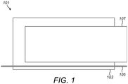
- Fig. 1 schematically illustrates an example apparatus 101.
- the example apparatus 101 comprises an insertion portion 103, heat transfer means 105 and removing means 107. It is to be appreciated that the apparatus 101 could comprise additional features in other examples of the disclosure.
- the insertion portion 103 may comprise a portion of the apparatus 101 that is sized and shaped so as to fit into the ear canal 211 of a subject.
- the insertion portion 103 may have dimensions such that the insertion portion 103 fits snugly into the ear canal 211 of the subject.
- the insertion portion 103 may have a length that prevents the insertion portion 103 from reaching the ear drum 215 of the subject when the insertion portion 103 is positioned within the ear canal 211.
- the apparatus 101 may be available with insertion portions 103 of different sizes. An apparatus 101 having an insertion portion 103 of the appropriate size can then be selected for the subject based on the size of their ear canal 211.
- the apparatus 101 may also comprise a portion that is not inserted into the ear canal 211 of the subject.
- the portion that is not inserted into the ear canal 211 may be provided at an end of the apparatus 101 and may be used to remove the apparatus 101 from the ear canal 211.
- the heat transfer means 105 may comprise any means that enables heat to be transferred from a heat source to a location within the ear canal 211.
- the heat transfer means 105 may be positioned within the insertion portion 103 so that, in use, the heat transfer means 105 can make thermal contact with the earwax 213.
- the thermal contact between the heat transfer means 105 and the earwax 213 enables the melting of the earwax 213 within the ear canal 211.
- the heat transfer means 105 extends through at least part of the insertion portion 103 so that heat can be transferred from a location outside of the ear canal 211 to a location within the ear canal 211. In the example shown in Fig. 1 the heat transfer means 105 extends along the entire length of the insertion portion 103. In the example shown in Fig. 1 the heat transfer means 105 extends out of the end of the insertion portion 103. This may facilitate thermal transfer between the heat transfer means 105 and the earwax 213.
- the heat transfer means 105 could comprise one or more heat pipes or any other thermal conductor that is configured to transfer heat to the earwax 213 within the ear canal 211.
- the heat transfer means 105 may comprise any suitable thermally conductive material.
- the heat transfer means 105 could comprise aluminium, copper or any other suitable material.
- the heat transfer means 105 may be insulated, or partially insulated, to prevent heat from leaking out of the heat transfer means 105 along the length of the insertion portion 103.
- the heat pipe may comprise an evaporator section, an adiabatic section and a condenser section.
- the evaporator section is located close to a heat source and is configured to enable heat to be transferred from the heat source to the heat pipe.
- the condenser section is located close to the section where the heat is to be provided to. In examples of the disclosure the condenser section may be located close to end of the insertion portion 103 so that the heat can be provided to the earwax 213.
- the adiabatic section is provided between the evaporator section and the condenser section and is configured to reduce the loss of heat as it is transported through the heat pipe.
- the apparatus 101 could comprise a heat source which is configured to provide heat to the heat transfer means 105.
- the heat source could be provided in a part of the apparatus 101 that is not inserted into the ear canal 211.
- the apparatus 101 could comprise means for coupling to another apparatus where the another apparatus comprises a heat source. In such examples the coupling to the another apparatus enables heat to be transferred from the heat source within the another apparatus to the heat transfer means 105. This therefore enables heat from another apparatus to be used to melt earwax 213 within an ear canal 211.
- the heat source could comprise any suitable means for generating heat.
- the heat source could comprise one or more electrical components.
- the electrical components could comprise processing circuitry, power sources or any other suitable components.
- the electrical components could generate heat as an auxiliary effect of performing other functions. The transfer of this heat by the heat transfer means 105 could therefore help with cooling of the electrical components.
- the removing means 107 may comprise any means which enables the melted earwax 213 to be removed from the ear canal 211.
- the removing means 107 comprises part of the insertion portion 103 so that, in use, the removing means 107 is positioned within the ear canal 211 of the subject. In examples of the disclosure the removing means 107 is provided at the end of the insertion portion 103 so that when the apparatus 101 is in use the removing means 107 contacts the earwax 213.
- the removing means 107 may be soft and/or deformable. This may make the apparatus 101 comfortable to be inserted into the ear canal 211. This may also help to prevent damage being caused to the ear drum 215 if the apparatus 101 is inserted too far into the ear canal 211.
- the removing means 107 comprises a wicking structure which is configured to remove melted earwax 213 from the ear canal 211 by capillary action.
- the wicking structure may comprise a mesh or other suitable structure which provides channels that enable the capillary action.
- the wicking structure may be formed using three dimensional printing. This may enable the size of the wicking structure to be controlled so that it fits into the ear canal of a subject. In some examples the use of three dimensional printing may also enable the size of the channels within the wicking structure to be controlled. This will affect the porosity of the wicking structure and how efficiently the wicking structure removes the melted earwax 213 from the ear canal 211.
- the removing means 107 may comprise a thermally conductive material. In such examples this may enable the removing means 107 to form part of the heat transfer means 105. This may enable heat to be transferred through the removing means 107 to the earwax 213 within the canal 211.
- the thermally conductive material could comprise a metal such as aluminium or any other suitable material.
- an anti-bacterial coating could be provided on at least part of the removing means 107.
- the anti-bacterial coating may reduce the risk of infections for the user.
- the anti-bacterial coating may comprise silver, silver alloys or any other suitable material.
- both the removing means 107 and the heat transfer means 105 comprise part of the insertion portion 103 so that the removing means 107 and the heat transfer means 105 can be positioned within the ear canal 211 of the subject at the same time.
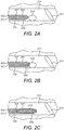
- Figs. 2A to 2C illustrate an example apparatus 101 at different stages of use.
- the apparatus 101 could be an apparatus 101 as shown in Fig. 1 and corresponding reference numerals are used for corresponding features.
- the heat transfer means 105 and the removing means 107 are provided as part of the insertion portion 103.
- the removing means 107 comprises a wicking structure 201.
- the wicking structure 201 comprises a mesh which forms channels that enable melted earwax 213 to be transferred via capillary action.
- the wicking structure 201 extends to the end of the insertion portion 103 so that when the insertion portion 103 is inserted into the ear canal 211 of the subject, the wicking structure 201 makes direct contact with the earwax 213.
- the heat transfer means 105 comprises a heat pipe 203 that extends along the length of the insertion portion 103.
- the heat pipe 203 is thermally coupled to the wicking structure 201 to enable heat to be transferred from the heat pipe 203 to the wicking structure 201.
- the wicking structure 201 may form part of the heat transfer means 105.
- Figs. 2A to 2C show an example of the apparatus 101 at different stages of use.
- the insertion portion 103 of the apparatus 101 is inserted into the ear canal 211 of the subject.
- the insertion portion 103 is sized so that the insertion portion 103 extends far enough along the ear canal 22 so that the end of the insertion portion 103 reaches the earwax 213 within the ear canal 211. This ensures that, at least part of, the wicking structure 201 comes into contact with the earwax 213 that is located in front of the ear drum 215.
- the wicking structure 201 may comprise a thermally conductive material so that heat can, at least partially, be transferred from the heat pipe 203 to the earwax 213 through the wicking structure 201.
- the heat pipe 203 may be positioned within the insertion portion 103 so that the heat pipe 203 contacts the earwax 213 directly. This may enable heat to be transferred directly from the heat pipe 203 to the earwax 213.
- the wicking structure 201 need not be comprise a thermally conductive material.
- Fig. 2A the apparatus 101 has just been inserted in the ear canal 211.
- the insertion portion 103 is pushed far enough into the ear canal 211 so that the wicking structure 201 contacts the earwax 213.
- the apparatus 101 has just been inserted no heat has been transferred to the earwax 213 yet so the earwax 213 is still provided in a solid form.
- Fig. 2B shows the same apparatus 101 as Fig. 2A after the apparatus 101 has been positioned within the ear canal 211 for some time. During this time heat has been provided through the heat pipe 203 and wicking structure 201 to the earwax 213. This has caused some of the earwax 213 to melt.
- Fig. 2C shows the same apparatus 101 as shown in Figs. 2A and 2B after the apparatus 101 has been positioned within the ear canal 211 for a longer period of time. During this time more heat has been provided through the heat pipe 203 and wicking structure 201 to the earwax 213 and this has caused all of the earwax 213 to melt.
- Fig. 2C all of the earwax 213 has been melted and drawn into the wicking structure 201.
- the melted earwax 213 will be removed with the wicking structure 201.
- all of the earwax 213 is melted so that when the apparatus 101 is removed from the ear canal 211 the ear canal 211 is clear of earwax 213.
- the time taken for the earwax 213 to be melted and absorbed by the wicking structure 201 may depend on a number of factors such as the amount of earwax 213 within the ear canal 211, the thermal efficiency of the heat transfer means 105, the porosity of the wicking structure 201 and any other suitable factor. In some examples it could take several hours or even days for the earwax 213 to be melted.
- the insertion portion 103 may therefore be comfortable enough so that it can be positioned within the ear canal 211 for this length of time. The comfort of the insertion portion 103 may be affected by factors such as the size of the insertion portion 103, the softness of the materials used for the insertion portion 103, antibacterial properties of the insertion portion 103 and any other suitable factors.
- the apparatus 101 may be configured to enable this deformation to be measured. This measurement can therefore provide an indication of the amount of earwax 213 that has been absorbed by the wicking structure 201.
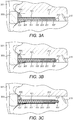
- Figs. 3A to 3C illustrate another example apparatus 101 in use.
- the example apparatus 101 shown in Figs. 3A to 3C also comprises an insertion portion 103, heat transfer means 105 and removing means 107.
- Corresponding reference numerals are used for corresponding features.
- the apparatus 101 also comprises a resilient means 301, a mount portion 303 and an ear cap 305.
- the heat transfer means 105 comprises a heat pipe 205 and the removing means 107 comprises as wicking structure 201 as shown in Figs. 2A to 2C . It is to be appreciated that other types and/or configurations of heat transfer means 105 and removing means 107 could be used in other examples of the disclosure.
- the resilient means 301 provides means for pushing the removing means 107 into the ear canal 211.
- the resilient means 301 may comprise any means which provides a force that pushes the removing means 107 into the ear canal 211.
- the resilient means 301 comprises a spring 311.
- the spring 311 is provided within the insertion portion 103.
- the spring 311 is coupled to the removing means 107.
- the spring 311 is coupled to the wicking structure 201 of the removing means 107 so that movement of the spring 311 causes movement of the wicking structure 201.
- the spring 311 and the wicking structure 201 are configured so that they can move relative to other components of the insertion portion 103.
- the spring 311 can be compressed or extended which allows for movement along the length of the insertion portion 103.
- the compression or extension of the spring 311 causes movement of the wicking structure 201 along the length of the ear canal 211. This may enable movement of the wicking structure 201 relative to other components of the insertion portion 103 such as the heat pipe 205.
- the apparatus 101 also comprises a mount portion 303.
- the mount portion 303 is provided on the opposite end of the insertion portion 103 to the removing means 107.
- the mount portion 303 comprises a portion that is not inserted into the ear canal 211 of the subject.
- the mount portion 303 is sized and shaped so that it does not fit into the ear canal 211.
- the mount portion 303 when the apparatus 101 is in use the mount portion 303 is located within the outer ear 321.
- the mount portion 303 may therefore prevent the insertion portion 103 from being inserted too far into the ear canal 211.
- the mount portion 303 may also be used to insert and remove the apparatus 201 from the subject's ear. For instance, the subject can grip the mount portion 303 to insert or remove the apparatus 101 as needed.
- the mount portion 303 may comprise any suitable material.
- the mount portion 303 may comprise a rigid material such as a plastic.
- the mount portion 303 may comprise additional components that are not shown in Figs. 3A to 3C .
- the mount portion 303 may comprise a heat source or means for coupling the heat transfer means 105 to an external heat source.
- the mount portion 303 could comprise electronic components.
- the electronic components could provide a function to the subject.
- the electronic components could provide audio and/or process audio for rendering to the subject.
- the electronic components could generate heat which could be provided to the heat transfer means 105.
- the apparatus 101 also comprises an ear cap 305.
- the ear cap 305 is coupled to the mount portion 303.
- the ear cap 305 is coupled to the mount portion 303 on the same side as the insertion portion 103 so that when the apparatus 101 is in use the ear cap 305 is positioned in the entrance of the ear canal 211.
- the ear cap 305 may comprise a flexible material.
- the ear cap 305 may provide a seal, or at least a partial seal, of the end of the ear canal 211.
- the ear cap 305 may help the apparatus 101 to fit comfortably into the ear of the subject.
- the ear cap 305 may help the apparatus 101 to fit into different sized and shaped ears.
- Fig. 3A the apparatus 101 has just been inserted in the ear canal 211.
- the insertion portion 103 is pushed far enough into the ear canal 211 so that the wicking structure 201 contacts the earwax 213.
- the apparatus 101 has just been inserted no heat has been transferred to the earwax 213 yet so the earwax 213 is still provided in a solid form.
- the solid earwax 213 provides a resistive force to the wicking structure 201 and the resilient means 301.
- the mount portion 303 is pushed into the ear so that the ear cap 305 fits tightly into the ear. This causes compression of the spring 311.
- the spring 311 is compressed so that the wicking structure 201 does not extend past the end of the heat pipe 105.
- Fig. 3B shows the same apparatus 101 as Fig. 3A after the apparatus 101 has been positioned within the ear canal 211 for some time. During this time heat has been provided through the heat pipe 203 and wicking structure 201 to the earwax 213. This has caused some of the earwax 213 to melt.
- the wicking structure 201 Once the earwax 213 has melted the melted earwax 213 is drawn into the wicking structure 201 by capillary action. This reduces the volume of earwax 213 within the ear canal 211 and so decreases the resistive force applied by the earwax 213. This causes some decompression of the spring 311 which pushes the wicking structure 201 further along the length of the ear canal 211. In the example shown in Fig. 3B the wicking structure 201 now extends past the end of the heat pipe 205. This movement of the wicking structure 201 ensures that, as the earwax 213 is melted, at least some of the earwax 213 remains in contact with the wicking structure 201.
- Fig. 3C shows the same apparatus 101 as shown in Figs. 3A and 3B after the apparatus 101 has been positioned within the ear canal 211 for a longer period of time. During this time more heat has been provided through the heat pipe 203 and wicking structure 201 to the earwax 213 and this has caused all of the earwax 213 to melt.
- Fig. 3C all of the earwax 213 has been melted and drawn into the wicking structure 201.
- the melted earwax 213 will be removed with the wicking structure 201.
- all of the earwax 213 is melted so that when the apparatus 101 is removed from the ear canal 211 the ear canal 211 is clear of earwax 213.
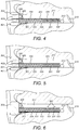
- Fig. 4 illustrates an earphone 401 comprising another example apparatus 101.
- the earphone 401 is configured to provide acoustic signals to the subject.
- the earphone 401 is an inner earphone or an ear bud.
- Other types of earphone 401 could be used in other examples of the disclosure.
- the example apparatus 101 shown in Fig. 4 also comprises an insertion portion 103, heat transfer means 105, removing means 107, resilient means 311, a mount portion 303 and an ear cap 305.
- the heat transfer means 105 comprises a heat pipe 205 and the removing means 107 comprises as wicking structure 201 as shown in Figs. 2A to 3C . It is to be appreciated that other types and/or configurations of heat transfer means 105 and removing means 107 could be used in other examples of the disclosure.
- the earphone 401 shown in Fig. 4 comprises electronic components 403 and an earphone output 405 in addition to the apparatus 101.
- the electronic components 403 are, at least partially, provided in the mount portion 303 of the apparatus 101.
- the electronic components could comprise sound transducers, processing circuitry, power sources and/or any other suitable electronic components 403.
- the earphone output 405 is provided on the mount portion 303.
- the earphone phone output 405 comprises an acoustic channel through which an acoustic signal can travel. This enables sound to be provided from the earphone 401 to the ear canal 211.
- the earphone output 405 is provided on the same side of the mount portion 303 as the insertion portion 103 so that, in use the earphone output 405 directs the acoustic signals towards the ear drum 215.
- the heat transfer means 105 is thermally coupled to the electronic components 403.
- the electronic components 403 may generate heat as they are performing functions relating to processing and/or audio rendering.
- the heat transfer means 105 enables this heat to be removed from the electronic components 403 and provided to the earwax 213 within the ear canal 211.
- the arrows 411 show the heat flow within the apparatus 101. This shows that heat travels from the electronic components 403, through the heat pipe 201 and wicking structure 201 to the earwax 213.
- the apparatus 101 is therefore configured to take unwanted heat from the electronic components 403 and use this to melt the earwax 213.
- This provides a device with dual functionality of providing acoustic signals and also removing earwax 213.
- the transfer of the heat away from the electronic components 403 also helps to cool the electronic components 403.
- the apparatus 101 could comprise a heat source which is configured just to provide heat for the heat transfer means 105.
- the heat source could be provided externally to the apparatus 101.
- the apparatus 101 could comprise coupling means which could be configured to couple the apparatus 101 to another apparatus which comprises a heat source.
- the another apparatus could be a head set such as a virtual reality headset or an augmented reality headset.
- Such apparatus may comprise processing circuitry and/or other components that generate heat that can be coupled to the heat transfer means 105.
- a pair of augmented or virtual reality glasses could comprise processing components in the arm of the glasses. When the glasses are in use these components would be positioned close to the subject's ear and could be thermally coupled to the heat transfer means 105.
- Fig. 5 illustrates an example earphone 401 comprising an apparatus 101.
- the earphone 401 and apparatus 101 shown in Fig. 5 are similar to the apparatus 101 and earphone 401 shown in Fig. 4 and corresponding reference numerals are used for corresponding features.
- the apparatus 101 also comprises a channel 501 which is configured to enable a solvent to be provided to the earwax 213.
- a channel 501 is shown, however it is to be appreciated that more than one channel 501 could be provided in other examples of the disclosure.
- the channel 501 extends along the length of the insertion portion 103.
- the channel 501 has an opening at the end of the insertion portion 103 to enable the solvent to flow from the channel 501 to the earwax 231.
- the channel 501 also extends through the mount portion 303 to the insertion portion 103. This enables ear drops or other solvents to be provided to the earwax 213 while the apparatus 101 is positioned within the subject's ear.
- the use of the solvents may soften the earwax 213 so that the earwax 213 melts more easily when the heat is provided by the heat transfer means 105. This may reduce the length of time that the apparatus 101 needs to be positioned within the subject's ear.
- channel 501 could also be provided within the apparatus 101 which do not form part of an earphone 401.
- one or more channels 501 could be provided within apparatus 101 such as the apparatus 101 shown in Figs. 2A to 3C .
- Fig. 6 illustrates another example apparatus 101.
- the example apparatus 101 is similar to that shown in Figs. 3A to 3C .
- the apparatus 1 also comprises one or more sensing means 601.
- the sensing means 601 may comprise any means that is configured to sense the amount of earwax 213 that has been absorbed by the wicking structure 201.
- the sensing means 601 are configured to detect deformation of the wicking structure 201 which is caused by the absorption of the melted earwax 213.
- the sensing means 601 comprises one or more strain sensors located within the insertion portion 103.
- the strain sensors maybe located within the walls of the insertion portion 103 adjacent to the wicking structure 201.
- the strain sensors 601 could be configured to measure this strain and use this measurement to determine how much earwax 213 has been absorbed by the wicking structure 201.
- the apparatus 101 comprises a plurality of strain sensors 601 where the strain sensors 601 are provided at different locations along the length of the insertion portion 103.
- different strain sensors 601 detect a strain this provides an indication of how far along the wicking structure 201 the earwax 213 has been absorbed. This also provides an indication of how much earwax 213 has been melted.
- the sensing means 601 could comprise means for sensing the position of the spring 311 and/or the load applied to the spring 311. This could sense how much the spring 311 has been compressed and/or how much the spring 311 has moved. This provides an indication of the resistive force applied by the solid earwax 213. This also provides an indication of how much earwax 213 has been melted and absorbed by the wicking structure 201.
- the apparatus 101 could comprise means for both sensing the deformation of the wicking structure 201 and for sensing the forces applied to the spring 311.
- the information from these different types of sensing means 601 could be used in combination to determine how much earwax 213 has been absorbed. In some examples this information could be used to determine whether or not all of the earwax 213 has been melted and absorbed by the wicking structure 201. This information could be used to provide an indication of when the apparatus 101 should be removed from the ear canal 211.
- the information from the sensing means 601 could be provided to processing circuitry.
- the processing circuitry could be configured to determine the amount of earwax removed and/or other information that may be useful for the subject.
- the processing circuitry could be provided in the mount portion 303 of the apparatus 101. In other examples the processing circuitry could be provided in another apparatus.
- the apparatus 101 could also comprise an output device which enables information obtained from the sensing means 601 to be provided to the subject.
- the apparatus 101 comprises part of an earphone 401 the earphone 401 may be configured to provide an audible output to the subject.
- the apparatus 101 could be coupled to another device such as a mobile device.
- the mobile device could comprise an application which links to the apparatus 101 and enables information from the sensing means 601 to be provided to the subject or other user, such as a medical professional.
- the apparatus 101 may be provided in configurations that differ to those shown in the Figs.
- Figs. 4 to 6 all show the use of a resilient means 301, a mount portion 303 and an ear cap 305 however one or more of these components could be omitted in some examples of the disclosure.
- examples of the disclosure provide an apparatus 101 that enables earwax 213 to be removed from an ear canal 211 by applying heat directly to the earwax 213.
- the apparatus 101 could also provide dual functionality in that it may be part of an earphone 401 or other suitable device and/or may assist with the cooling of electronic components 403.
- coupled means operationally coupled and any number or combination of intervening elements can exist between coupled components including no intervening elements.
- 'comprise' is used in this document with an inclusive not an exclusive meaning. That is any reference to X comprising Y indicates that X may comprise only one Y or may comprise more than one Y. If it is intended to use 'comprise' with an exclusive meaning then it will be made clear in the context by referring to 'comprising only one...' or by using 'consisting'.
- a property of the instance can be a property of only that instance or a property of the class or a property of a subclass of the class that includes some but not all of the instances in the class. It is therefore implicitly disclosed that a feature described with reference to one example but not with reference to another example, can where possible be used in that other example as part of a working combination but does not necessarily have to be used in that other example.
- 'a' or 'the' is used in this document with an inclusive not an exclusive meaning. That is any reference to X comprising a/the Y indicates that X may comprise only one Y or may comprise more than one Y unless the context clearly indicates the contrary. If it is intended to use 'a' or 'the' with an exclusive meaning then it will be made clear in the context. In some circumstances the use of 'at least one' or 'one or more' may be used to emphasis an inclusive meaning but the absence of these terms should not be taken to infer and exclusive meaning.
- the presence of a feature (or combination of features) in a claim is a reference to that feature or (combination of features) itself and also to features that achieve substantially the same technical effect (equivalent features).
- the equivalent features include, for example, features that are variants and achieve substantially the same result in substantially the same way.
- the equivalent features include, for example, features that perform substantially the same function, in substantially the same way to achieve substantially the same result.
Landscapes
- Health & Medical Sciences (AREA)
- Life Sciences & Earth Sciences (AREA)
- General Health & Medical Sciences (AREA)
- Public Health (AREA)
- Heart & Thoracic Surgery (AREA)
- Vascular Medicine (AREA)
- Engineering & Computer Science (AREA)
- Animal Behavior & Ethology (AREA)
- Veterinary Medicine (AREA)
- Biomedical Technology (AREA)
- Epidemiology (AREA)
- Physics & Mathematics (AREA)
- Acoustics & Sound (AREA)
- Biophysics (AREA)
- Otolaryngology (AREA)
- Psychology (AREA)
- Thermotherapy And Cooling Therapy Devices (AREA)
Abstract
Examples of the disclosure relate to an apparatus for removing earwax from the ear canal of a subject. The apparatus comprises an insertion portion which is configured to be inserted into the ear canal of the subject. The apparatus also comprises a heat transfer means. The heat transfer means is configured so that heat can be transferred through the insertion portion to the earwax within the ear canal so as to enable the earwax to be melted. The apparatus also comprises removing means which are configured to remove the melted earwax from the ear canal.
Description
- Examples of the present disclosure relate to apparatus and earphones for removing earwax. Some relate to apparatus and earphones for removing earwax by using heat.
- Earwax (cerumen) occurs naturally and has the function of cleaning and protecting the ear canal. However, due to the shape of the ear canal earwax can deposit in specific locations. If this waxy build-up is not cleared the earwax can accumulate, sediment and compact into a hardened mass which can be difficult to remove. This accumulation of earwax can lead to numerous issues including discomfort, infection, reduced hearing or even loss of hearing.
- According to various, but not necessarily all, examples of the disclosure there may be provided an apparatus for removing earwax, the apparatus comprising: an insertion portion configured to be inserted into the ear canal of a subject; heat transfer means for transferring heat through, at least part of, the insertion portion to earwax within the ear canal to enable melting of the earwax within the ear canal; and removing means for removing the melted earwax from the ear canal.
- The removing means may comprise a wicking structure configured to remove melted earwax from the ear canal by capillary action. The wicking structure may comprise a mesh. The apparatus may comprise sensing means for sensing the amount of earwax that has been absorbed by the wicking structure. The sensing means may be configured to detect deformation of the wicking structure which is caused by the absorption of the melted earwax.
- The removing means may comprise a thermally conductive material so that the removing means forms part of the heat transferring means.
- An anti-bacterial coating may be provided on at least part of the removing means
- The heat transfer means may comprise one or more heat pipes located within the insertion portion.
- The apparatus may comprise a heat source configured to provide heat to the heat transfer means.
- The heat transfer means may be configured to be coupled to a heat source where the heat source is provided in a different apparatus so as to enable heat from the heat source to be provided to the heat transferring means.
- The heat source may comprise one or more electrical components.
- The insertion portion may comprise resilient means for pushing the removing means into the ear canal.
- The resilient means may comprise at least one spring coupled to the removing means.
- The insertion portion may comprise one or more channels configured to enable a solvent to be provided to the earwax.
- According to various, but not necessarily all, examples of the disclosure there may be provided an earphone comprising: an apparatus for removing earwax, the apparatus comprising: an insertion portion configured to be inserted into the ear canal of a subject; heat transfer means for transferring heat through, at least part of, the insertion portion to earwax within the ear canal to enable melting of the earwax within the ear canal; and removing means for removing the melted earwax from the ear canal; and at least one sound transducer.
- The earphone may comprise processing circuitry wherein the processing circuitry may be thermally coupled to the heat transfer means.
- According to various, but not necessarily all, examples of the disclosure there may be provided an apparatus for removing earwax, the apparatus comprising: an insertion portion configured to be inserted into the ear canal of a subject; at least one heat transfer portion configured to transferring heat through, at least part of, the insertion portion to earwax within the ear canal to enable melting of the earwax within the ear canal; and at least one remover configured to remove the melted earwax from the ear canal.
- Some example embodiments will now be described with reference to the accompanying drawings in which:
-
Fig. 1 illustrates an example apparatus; -
Figs. 2A to 2C illustrate an example apparatus in use; -
Figs. 3A to 3C illustrate another example apparatus in use; -
Fig. 4 illustrates an example earphone; -
Fig. 5 illustrates an example earphone; and -
Fig. 6 illustrates an example apparatus. - Examples of the disclosure relate to an
apparatus 101 for removingearwax 213 from theear canal 211 of a subject. Theapparatus 101 comprises aninsertion portion 103 which is configured to be inserted into theear canal 211 of the subject. Theapparatus 101 also comprises a heat transfer means 105. The heat transfer means 105 is configured so that heat can be transferred through theinsertion portion 103 to theearwax 213 within theear canal 211 so as to enable theearwax 213 to be melted. Theapparatus 101 also comprises removingmeans 107 which are configured to remove the meltedearwax 213 from the ear canal. - The
apparatus 101 therefore provides a safe and effective way of removingearwax 213 from anear canal 211 of a subject. Theapparatus 101 could be incorporated into electronic devices such as ear pieces. This may enable the electronic devices to provide dual functionality such as providing audio to a subject while also enabling the earwax to be removed from the subject's ears. -
Fig. 1 schematically illustrates anexample apparatus 101. Theexample apparatus 101 comprises aninsertion portion 103, heat transfer means 105 and removingmeans 107. It is to be appreciated that theapparatus 101 could comprise additional features in other examples of the disclosure. - The
insertion portion 103 may comprise a portion of theapparatus 101 that is sized and shaped so as to fit into theear canal 211 of a subject. Theinsertion portion 103 may have dimensions such that theinsertion portion 103 fits snugly into theear canal 211 of the subject. - The
insertion portion 103 may have a length that prevents theinsertion portion 103 from reaching theear drum 215 of the subject when theinsertion portion 103 is positioned within theear canal 211. In some examples theapparatus 101 may be available withinsertion portions 103 of different sizes. Anapparatus 101 having aninsertion portion 103 of the appropriate size can then be selected for the subject based on the size of theirear canal 211. - In some examples the
apparatus 101 may also comprise a portion that is not inserted into theear canal 211 of the subject. The portion that is not inserted into theear canal 211 may be provided at an end of theapparatus 101 and may be used to remove theapparatus 101 from theear canal 211. - The heat transfer means 105 may comprise any means that enables heat to be transferred from a heat source to a location within the
ear canal 211. The heat transfer means 105 may be positioned within theinsertion portion 103 so that, in use, the heat transfer means 105 can make thermal contact with theearwax 213. The thermal contact between the heat transfer means 105 and theearwax 213 enables the melting of theearwax 213 within theear canal 211. - The heat transfer means 105 extends through at least part of the
insertion portion 103 so that heat can be transferred from a location outside of theear canal 211 to a location within theear canal 211. In the example shown inFig. 1 the heat transfer means 105 extends along the entire length of theinsertion portion 103. In the example shown inFig. 1 the heat transfer means 105 extends out of the end of theinsertion portion 103. This may facilitate thermal transfer between the heat transfer means 105 and theearwax 213. - The heat transfer means 105 could comprise one or more heat pipes or any other thermal conductor that is configured to transfer heat to the
earwax 213 within theear canal 211. The heat transfer means 105 may comprise any suitable thermally conductive material. For instance the heat transfer means 105 could comprise aluminium, copper or any other suitable material. In some examples the heat transfer means 105 may be insulated, or partially insulated, to prevent heat from leaking out of the heat transfer means 105 along the length of theinsertion portion 103. - The heat pipe may comprise an evaporator section, an adiabatic section and a condenser section. The evaporator section is located close to a heat source and is configured to enable heat to be transferred from the heat source to the heat pipe. The condenser section is located close to the section where the heat is to be provided to. In examples of the disclosure the condenser section may be located close to end of the
insertion portion 103 so that the heat can be provided to theearwax 213. The adiabatic section is provided between the evaporator section and the condenser section and is configured to reduce the loss of heat as it is transported through the heat pipe. - In some examples the
apparatus 101 could comprise a heat source which is configured to provide heat to the heat transfer means 105. The heat source could be provided in a part of theapparatus 101 that is not inserted into theear canal 211. In other examples theapparatus 101 could comprise means for coupling to another apparatus where the another apparatus comprises a heat source. In such examples the coupling to the another apparatus enables heat to be transferred from the heat source within the another apparatus to the heat transfer means 105. This therefore enables heat from another apparatus to be used to meltearwax 213 within anear canal 211. - The heat source could comprise any suitable means for generating heat. In some examples the heat source could comprise one or more electrical components. The electrical components could comprise processing circuitry, power sources or any other suitable components. The electrical components could generate heat as an auxiliary effect of performing other functions. The transfer of this heat by the heat transfer means 105 could therefore help with cooling of the electrical components.
- The removing means 107 may comprise any means which enables the melted
earwax 213 to be removed from theear canal 211. - In the examples of the disclosure the removing means 107 comprises part of the
insertion portion 103 so that, in use, the removing means 107 is positioned within theear canal 211 of the subject. In examples of the disclosure the removing means 107 is provided at the end of theinsertion portion 103 so that when theapparatus 101 is in use the removing means 107 contacts theearwax 213. - In some examples the removing means 107 may be soft and/or deformable. This may make the
apparatus 101 comfortable to be inserted into theear canal 211. This may also help to prevent damage being caused to theear drum 215 if theapparatus 101 is inserted too far into theear canal 211. - In some examples the removing means 107 comprises a wicking structure which is configured to remove melted
earwax 213 from theear canal 211 by capillary action. The wicking structure may comprise a mesh or other suitable structure which provides channels that enable the capillary action. - In some examples the wicking structure may be formed using three dimensional printing. This may enable the size of the wicking structure to be controlled so that it fits into the ear canal of a subject. In some examples the use of three dimensional printing may also enable the size of the channels within the wicking structure to be controlled. This will affect the porosity of the wicking structure and how efficiently the wicking structure removes the melted
earwax 213 from theear canal 211. - In some examples the removing means 107 may comprise a thermally conductive material. In such examples this may enable the removing means 107 to form part of the heat transfer means 105. This may enable heat to be transferred through the removing means 107 to the
earwax 213 within thecanal 211. The thermally conductive material could comprise a metal such as aluminium or any other suitable material. - In some examples an anti-bacterial coating could be provided on at least part of the removing
means 107. The anti-bacterial coating may reduce the risk of infections for the user. The anti-bacterial coating may comprise silver, silver alloys or any other suitable material. - In examples of the disclosure both the removing means 107 and the heat transfer means 105 comprise part of the
insertion portion 103 so that the removing means 107 and the heat transfer means 105 can be positioned within theear canal 211 of the subject at the same time. This makes theapparatus 101 simple for a subject to use because they can insert theapparatus 101 into their ear and then leave it until theearwax 213 has been removed by the removingmeans 107. There is no need for separate steps such as syringing or irrigation in order to remove theearwax 213. -
Figs. 2A to 2C illustrate anexample apparatus 101 at different stages of use. Theapparatus 101 could be anapparatus 101 as shown inFig. 1 and corresponding reference numerals are used for corresponding features. In the example shown inFigs. 2A to 2C the heat transfer means 105 and the removing means 107 are provided as part of theinsertion portion 103. - In the example shown in
Figs. 2A to 2C the removing means 107 comprises awicking structure 201. Thewicking structure 201 comprises a mesh which forms channels that enable meltedearwax 213 to be transferred via capillary action. Thewicking structure 201 extends to the end of theinsertion portion 103 so that when theinsertion portion 103 is inserted into theear canal 211 of the subject, thewicking structure 201 makes direct contact with theearwax 213. - In the example shown in
Figs. 2A to 2C the heat transfer means 105 comprises aheat pipe 203 that extends along the length of theinsertion portion 103. Theheat pipe 203 is thermally coupled to thewicking structure 201 to enable heat to be transferred from theheat pipe 203 to thewicking structure 201. In this example thewicking structure 201 may form part of the heat transfer means 105. -
Figs. 2A to 2C show an example of theapparatus 101 at different stages of use. In the example shown inFig. 2A theinsertion portion 103 of theapparatus 101 is inserted into theear canal 211 of the subject. Theinsertion portion 103 is sized so that theinsertion portion 103 extends far enough along the ear canal 22 so that the end of theinsertion portion 103 reaches theearwax 213 within theear canal 211. This ensures that, at least part of, thewicking structure 201 comes into contact with theearwax 213 that is located in front of theear drum 215. - In this example the
wicking structure 201 may comprise a thermally conductive material so that heat can, at least partially, be transferred from theheat pipe 203 to theearwax 213 through thewicking structure 201. In other examples theheat pipe 203 may be positioned within theinsertion portion 103 so that theheat pipe 203 contacts theearwax 213 directly. This may enable heat to be transferred directly from theheat pipe 203 to theearwax 213. In such examples thewicking structure 201 need not be comprise a thermally conductive material. - In
Fig. 2A theapparatus 101 has just been inserted in theear canal 211. Theinsertion portion 103 is pushed far enough into theear canal 211 so that thewicking structure 201 contacts theearwax 213. As theapparatus 101 has just been inserted no heat has been transferred to theearwax 213 yet so theearwax 213 is still provided in a solid form. -
Fig. 2B shows thesame apparatus 101 asFig. 2A after theapparatus 101 has been positioned within theear canal 211 for some time. During this time heat has been provided through theheat pipe 203 andwicking structure 201 to theearwax 213. This has caused some of theearwax 213 to melt. - Once the
earwax 213 has melted the meltedearwax 213 is drawn into thewicking structure 201 by capillary action. -
Fig. 2C shows thesame apparatus 101 as shown inFigs. 2A and 2B after theapparatus 101 has been positioned within theear canal 211 for a longer period of time. During this time more heat has been provided through theheat pipe 203 andwicking structure 201 to theearwax 213 and this has caused all of theearwax 213 to melt. - In
Fig. 2C all of theearwax 213 has been melted and drawn into thewicking structure 201. When theapparatus 101 is removed from theear canal 211 the meltedearwax 213 will be removed with thewicking structure 201. In the example shown inFig. 2C all of theearwax 213 is melted so that when theapparatus 101 is removed from theear canal 211 theear canal 211 is clear ofearwax 213. - The time taken for the
earwax 213 to be melted and absorbed by thewicking structure 201 may depend on a number of factors such as the amount ofearwax 213 within theear canal 211, the thermal efficiency of the heat transfer means 105, the porosity of thewicking structure 201 and any other suitable factor. In some examples it could take several hours or even days for theearwax 213 to be melted. Theinsertion portion 103 may therefore be comfortable enough so that it can be positioned within theear canal 211 for this length of time. The comfort of theinsertion portion 103 may be affected by factors such as the size of theinsertion portion 103, the softness of the materials used for theinsertion portion 103, antibacterial properties of theinsertion portion 103 and any other suitable factors. - As the melted
earwax 213 is absorbed by thewicking structure 201 it causes deformation of thewicking structure 201. The additional material that is now comprised within thewicking structure 201 may cause bending or bowing of thewicking structure 201. In some examples theapparatus 101 may be configured to enable this deformation to be measured. This measurement can therefore provide an indication of the amount ofearwax 213 that has been absorbed by thewicking structure 201. -
Figs. 3A to 3C illustrate anotherexample apparatus 101 in use. Theexample apparatus 101 shown inFigs. 3A to 3C also comprises aninsertion portion 103, heat transfer means 105 and removingmeans 107. Corresponding reference numerals are used for corresponding features. In the example shown inFigs. 3A to 3C theapparatus 101 also comprises aresilient means 301, amount portion 303 and anear cap 305. In the example shown inFigs. 3A to 3C the heat transfer means 105 comprises aheat pipe 205 and the removing means 107 comprises aswicking structure 201 as shown inFigs. 2A to 2C . It is to be appreciated that other types and/or configurations of heat transfer means 105 and removingmeans 107 could be used in other examples of the disclosure. - The resilient means 301 provides means for pushing the removing means 107 into the
ear canal 211. The resilient means 301 may comprise any means which provides a force that pushes the removing means 107 into theear canal 211. In the example shown inFigs. 3A to 3C theresilient means 301 comprises aspring 311. Thespring 311 is provided within theinsertion portion 103. Thespring 311 is coupled to the removingmeans 107. In the example shown inFigs. 3A to 3C thespring 311 is coupled to thewicking structure 201 of the removing means 107 so that movement of thespring 311 causes movement of thewicking structure 201. - In the examples shown in
Figs. 3A to 3C thespring 311 and thewicking structure 201 are configured so that they can move relative to other components of theinsertion portion 103. In the examples shown thespring 311 can be compressed or extended which allows for movement along the length of theinsertion portion 103. As thewicking structure 201 is coupled to thespring 311 the compression or extension of thespring 311 causes movement of thewicking structure 201 along the length of theear canal 211. This may enable movement of thewicking structure 201 relative to other components of theinsertion portion 103 such as theheat pipe 205. - The
apparatus 101 also comprises amount portion 303. Themount portion 303 is provided on the opposite end of theinsertion portion 103 to the removingmeans 107. Themount portion 303 comprises a portion that is not inserted into theear canal 211 of the subject. Themount portion 303 is sized and shaped so that it does not fit into theear canal 211. - As shown in
Figs. 3A to 3C , when theapparatus 101 is in use themount portion 303 is located within theouter ear 321. Themount portion 303 may therefore prevent theinsertion portion 103 from being inserted too far into theear canal 211. Themount portion 303 may also be used to insert and remove theapparatus 201 from the subject's ear. For instance, the subject can grip themount portion 303 to insert or remove theapparatus 101 as needed. - The
mount portion 303 may comprise any suitable material. In some examples themount portion 303 may comprise a rigid material such as a plastic. - In some examples the
mount portion 303 may comprise additional components that are not shown inFigs. 3A to 3C . For instance themount portion 303 may comprise a heat source or means for coupling the heat transfer means 105 to an external heat source. In some examples themount portion 303 could comprise electronic components. The electronic components could provide a function to the subject. For example the electronic components could provide audio and/or process audio for rendering to the subject. In such examples the electronic components could generate heat which could be provided to the heat transfer means 105. - In the example shown in
Figs. 3A to 3C theapparatus 101 also comprises anear cap 305. Theear cap 305 is coupled to themount portion 303. Theear cap 305 is coupled to themount portion 303 on the same side as theinsertion portion 103 so that when theapparatus 101 is in use theear cap 305 is positioned in the entrance of theear canal 211. - The
ear cap 305 may comprise a flexible material. Theear cap 305 may provide a seal, or at least a partial seal, of the end of theear canal 211. Theear cap 305 may help theapparatus 101 to fit comfortably into the ear of the subject. Theear cap 305 may help theapparatus 101 to fit into different sized and shaped ears. - In
Fig. 3A theapparatus 101 has just been inserted in theear canal 211. Theinsertion portion 103 is pushed far enough into theear canal 211 so that thewicking structure 201 contacts theearwax 213. As theapparatus 101 has just been inserted no heat has been transferred to theearwax 213 yet so theearwax 213 is still provided in a solid form. - The
solid earwax 213 provides a resistive force to thewicking structure 201 and theresilient means 301. Themount portion 303 is pushed into the ear so that theear cap 305 fits tightly into the ear. This causes compression of thespring 311. In the configuration shown inFig. 3A thespring 311 is compressed so that thewicking structure 201 does not extend past the end of theheat pipe 105. -
Fig. 3B shows thesame apparatus 101 asFig. 3A after theapparatus 101 has been positioned within theear canal 211 for some time. During this time heat has been provided through theheat pipe 203 andwicking structure 201 to theearwax 213. This has caused some of theearwax 213 to melt. - Once the
earwax 213 has melted the meltedearwax 213 is drawn into thewicking structure 201 by capillary action. This reduces the volume ofearwax 213 within theear canal 211 and so decreases the resistive force applied by theearwax 213. This causes some decompression of thespring 311 which pushes thewicking structure 201 further along the length of theear canal 211. In the example shown inFig. 3B thewicking structure 201 now extends past the end of theheat pipe 205. This movement of thewicking structure 201 ensures that, as theearwax 213 is melted, at least some of theearwax 213 remains in contact with thewicking structure 201. -
Fig. 3C shows thesame apparatus 101 as shown inFigs. 3A and 3B after theapparatus 101 has been positioned within theear canal 211 for a longer period of time. During this time more heat has been provided through theheat pipe 203 andwicking structure 201 to theearwax 213 and this has caused all of theearwax 213 to melt. - In
Fig. 3C all of theearwax 213 has been melted and drawn into thewicking structure 201. When theapparatus 101 is removed from theear canal 211 the meltedearwax 213 will be removed with thewicking structure 201. In the example shown inFig. 3C all of theearwax 213 is melted so that when theapparatus 101 is removed from theear canal 211 theear canal 211 is clear ofearwax 213. - In the example shown in
Fig. 3C all of theearwax 213 is now absorbed within thewicking structure 201. In this case there is no moresolid earwax 213 to provide a resistive force to thewicking structure 201 andspring 311. This causes some decompression of thespring 311 which pushes thewicking structure 201 even further along the length of theear canal 211. In this configuration thewicking structure 201 extends further past the end of theheat pipe 203. -
Fig. 4 illustrates anearphone 401 comprising anotherexample apparatus 101. Theearphone 401 is configured to provide acoustic signals to the subject. In the example shown inFig. 4 theearphone 401 is an inner earphone or an ear bud. Other types ofearphone 401 could be used in other examples of the disclosure. - The
example apparatus 101 shown inFig. 4 also comprises aninsertion portion 103, heat transfer means 105, removing means 107, resilient means 311, amount portion 303 and anear cap 305. Corresponding reference numerals are used for corresponding features. In the example shown inFig. 4 the heat transfer means 105 comprises aheat pipe 205 and the removing means 107 comprises aswicking structure 201 as shown inFigs. 2A to 3C . It is to be appreciated that other types and/or configurations of heat transfer means 105 and removingmeans 107 could be used in other examples of the disclosure. - The
earphone 401 shown inFig. 4 compriseselectronic components 403 and anearphone output 405 in addition to theapparatus 101. - In the example of
Fig. 4 theelectronic components 403 are, at least partially, provided in themount portion 303 of theapparatus 101. The electronic components could comprise sound transducers, processing circuitry, power sources and/or any other suitableelectronic components 403. - The
earphone output 405 is provided on themount portion 303. Theearphone phone output 405 comprises an acoustic channel through which an acoustic signal can travel. This enables sound to be provided from theearphone 401 to theear canal 211. - The
earphone output 405 is provided on the same side of themount portion 303 as theinsertion portion 103 so that, in use theearphone output 405 directs the acoustic signals towards theear drum 215. - In the examples shown in
Fig. 4 the heat transfer means 105 is thermally coupled to theelectronic components 403. Theelectronic components 403 may generate heat as they are performing functions relating to processing and/or audio rendering. The heat transfer means 105 enables this heat to be removed from theelectronic components 403 and provided to theearwax 213 within theear canal 211. - In the example shown in
Fig. 4 thearrows 411 show the heat flow within theapparatus 101. This shows that heat travels from theelectronic components 403, through theheat pipe 201 andwicking structure 201 to theearwax 213. - In the example of
Fig. 4 theapparatus 101 is therefore configured to take unwanted heat from theelectronic components 403 and use this to melt theearwax 213. This provides a device with dual functionality of providing acoustic signals and also removingearwax 213. The transfer of the heat away from theelectronic components 403 also helps to cool theelectronic components 403. - In other examples instead of
electronic components 403 theapparatus 101 could comprise a heat source which is configured just to provide heat for the heat transfer means 105. - In other examples the heat source could be provided externally to the
apparatus 101. In such examples theapparatus 101 could comprise coupling means which could be configured to couple theapparatus 101 to another apparatus which comprises a heat source. The another apparatus could be a head set such as a virtual reality headset or an augmented reality headset. Such apparatus may comprise processing circuitry and/or other components that generate heat that can be coupled to the heat transfer means 105. For example a pair of augmented or virtual reality glasses could comprise processing components in the arm of the glasses. When the glasses are in use these components would be positioned close to the subject's ear and could be thermally coupled to the heat transfer means 105. -
Fig. 5 illustrates anexample earphone 401 comprising anapparatus 101. Theearphone 401 andapparatus 101 shown inFig. 5 are similar to theapparatus 101 andearphone 401 shown inFig. 4 and corresponding reference numerals are used for corresponding features. - In the
example earphone 401 shown inFig. 5 theapparatus 101 also comprises achannel 501 which is configured to enable a solvent to be provided to theearwax 213. In the example ofFig. 5 onechannel 501 is shown, however it is to be appreciated that more than onechannel 501 could be provided in other examples of the disclosure. - The
channel 501 extends along the length of theinsertion portion 103. Thechannel 501 has an opening at the end of theinsertion portion 103 to enable the solvent to flow from thechannel 501 to the earwax 231. In the example shown inFig. 5 thechannel 501 also extends through themount portion 303 to theinsertion portion 103. This enables ear drops or other solvents to be provided to theearwax 213 while theapparatus 101 is positioned within the subject's ear. The use of the solvents may soften theearwax 213 so that theearwax 213 melts more easily when the heat is provided by the heat transfer means 105. This may reduce the length of time that theapparatus 101 needs to be positioned within the subject's ear. - It is to be appreciated that the
channel 501 could also be provided within theapparatus 101 which do not form part of anearphone 401. For instance one ormore channels 501 could be provided withinapparatus 101 such as theapparatus 101 shown inFigs. 2A to 3C . -
Fig. 6 illustrates anotherexample apparatus 101. Theexample apparatus 101 is similar to that shown inFigs. 3A to 3C . In the example ofFig. 6 the apparatus 1 also comprises one or more sensing means 601. - The sensing means 601 may comprise any means that is configured to sense the amount of
earwax 213 that has been absorbed by thewicking structure 201. - In the example shown in
Fig. 6 the sensing means 601 are configured to detect deformation of thewicking structure 201 which is caused by the absorption of the meltedearwax 213. In the example shown inFig. 6 the sensing means 601 comprises one or more strain sensors located within theinsertion portion 103. The strain sensors maybe located within the walls of theinsertion portion 103 adjacent to thewicking structure 201. When thewicking structure 201 absorbs meltedearwax 213 the extra material absorbed by thewicking structure 201 causes thewicking structure 201 to expand. The expansion of thewicking structure 201 causes strain to be applied to theinsertion portion 103. Thestrain sensors 601 could be configured to measure this strain and use this measurement to determine howmuch earwax 213 has been absorbed by thewicking structure 201. - In some examples the
apparatus 101 comprises a plurality ofstrain sensors 601 where thestrain sensors 601 are provided at different locations along the length of theinsertion portion 103. Whendifferent strain sensors 601 detect a strain this provides an indication of how far along thewicking structure 201 theearwax 213 has been absorbed. This also provides an indication of howmuch earwax 213 has been melted. - In other examples the sensing means 601 could comprise means for sensing the position of the
spring 311 and/or the load applied to thespring 311. This could sense how much thespring 311 has been compressed and/or how much thespring 311 has moved. This provides an indication of the resistive force applied by thesolid earwax 213. This also provides an indication of howmuch earwax 213 has been melted and absorbed by thewicking structure 201. - In some examples the
apparatus 101 could comprise means for both sensing the deformation of thewicking structure 201 and for sensing the forces applied to thespring 311. The information from these different types of sensing means 601 could be used in combination to determine howmuch earwax 213 has been absorbed. In some examples this information could be used to determine whether or not all of theearwax 213 has been melted and absorbed by thewicking structure 201. This information could be used to provide an indication of when theapparatus 101 should be removed from theear canal 211. - In some examples the information from the sensing means 601 could be provided to processing circuitry. The processing circuitry could be configured to determine the amount of earwax removed and/or other information that may be useful for the subject. In some examples the processing circuitry could be provided in the
mount portion 303 of theapparatus 101. In other examples the processing circuitry could be provided in another apparatus. - In some examples the
apparatus 101 could also comprise an output device which enables information obtained from the sensing means 601 to be provided to the subject. For instance, where theapparatus 101 comprises part of anearphone 401 theearphone 401 may be configured to provide an audible output to the subject. In other examples theapparatus 101 could be coupled to another device such as a mobile device. The mobile device could comprise an application which links to theapparatus 101 and enables information from the sensing means 601 to be provided to the subject or other user, such as a medical professional. - It is to be appreciated that the
apparatus 101 may be provided in configurations that differ to those shown in the Figs. For instanceFigs. 4 to 6 all show the use of aresilient means 301, amount portion 303 and anear cap 305 however one or more of these components could be omitted in some examples of the disclosure. - Therefore examples of the disclosure provide an
apparatus 101 that enablesearwax 213 to be removed from anear canal 211 by applying heat directly to theearwax 213. Theapparatus 101 could also provide dual functionality in that it may be part of anearphone 401 or other suitable device and/or may assist with the cooling ofelectronic components 403. - In this description the term coupled means operationally coupled and any number or combination of intervening elements can exist between coupled components including no intervening elements.
- The term 'comprise' is used in this document with an inclusive not an exclusive meaning. That is any reference to X comprising Y indicates that X may comprise only one Y or may comprise more than one Y. If it is intended to use 'comprise' with an exclusive meaning then it will be made clear in the context by referring to 'comprising only one...' or by using 'consisting'.
- In this description, reference has been made to various examples. The description of features or functions in relation to an example indicates that those features or functions are present in that example. The use of the term 'example' or 'for example' or 'can' or 'may' in the text denotes, whether explicitly stated or not, that such features or functions are present in at least the described example, whether described as an example or not, and that they can be, but are not necessarily, present in some of or all other examples. Thus 'example', 'for example', 'can' or 'may' refers to a particular instance in a class of examples. A property of the instance can be a property of only that instance or a property of the class or a property of a subclass of the class that includes some but not all of the instances in the class. It is therefore implicitly disclosed that a feature described with reference to one example but not with reference to another example, can where possible be used in that other example as part of a working combination but does not necessarily have to be used in that other example.
- Although embodiments have been described in the preceding paragraphs with reference to various examples, it should be appreciated that modifications to the examples given can be made without departing from the scope of the claims.
- Features described in the preceding description may be used in combinations other than the combinations explicitly described above.
- Although functions have been described with reference to certain features, those functions may be performable by other features whether described or not.
- Although features have been described with reference to certain embodiments, those features may also be present in other embodiments whether described or not.
- The term 'a' or 'the' is used in this document with an inclusive not an exclusive meaning. That is any reference to X comprising a/the Y indicates that X may comprise only one Y or may comprise more than one Y unless the context clearly indicates the contrary. If it is intended to use 'a' or 'the' with an exclusive meaning then it will be made clear in the context. In some circumstances the use of 'at least one' or 'one or more' may be used to emphasis an inclusive meaning but the absence of these terms should not be taken to infer and exclusive meaning.
- The presence of a feature (or combination of features) in a claim is a reference to that feature or (combination of features) itself and also to features that achieve substantially the same technical effect (equivalent features). The equivalent features include, for example, features that are variants and achieve substantially the same result in substantially the same way. The equivalent features include, for example, features that perform substantially the same function, in substantially the same way to achieve substantially the same result.
- In this description, reference has been made to various examples using adjectives or adjectival phrases to describe characteristics of the examples. Such a description of a characteristic in relation to an example indicates that the characteristic is present in some examples exactly as described and is present in other examples substantially as described.
- Whilst endeavoring in the foregoing specification to draw attention to those features believed to be of importance it should be understood that the Applicant may seek protection via the claims in respect of any patentable feature or combination of features hereinbefore referred to and/or shown in the drawings whether or not emphasis has been placed thereon.
Claims (15)
- An apparatus for removing earwax, the apparatus comprising:an insertion portion configured to be inserted into the ear canal of a subject;heat transfer means for transferring heat through, at least part of, the insertion portion to earwax within the ear canal to enable melting of the earwax within the ear canal; andremoving means for removing the melted earwax from the ear canal.
- An apparatus as claimed in claim 1 wherein the removing means comprises a wicking structure configured to remove melted earwax from the ear canal by capillary action.
- An apparatus as claimed in claim 2 wherein the wicking structure comprises a mesh.
- An apparatus as claimed in any of claims 2 to 3 comprising sensing means for sensing the amount of earwax that has been absorbed by the wicking structure.
- An apparatus as claimed in claim 4 wherein the sensing means are configured to detect deformation of the wicking structure which is caused by the absorption of the melted earwax.
- An apparatus as claimed in any preceding claim wherein the removing means comprises a thermally conductive material so that the removing means forms part of the heat transferring means.
- An apparatus as claimed in any preceding claim wherein an anti-bacterial coating is provided on at least part of the removing means
- An apparatus as claimed in any preceding claim wherein the heat transfer means comprises one or more heat pipes located within the insertion portion.
- An apparatus as claimed in any preceding claim wherein the apparatus comprises a heat source configured to provide heat to the heat transfer means.
- An apparatus as claimed in any of claims 1 to 8 wherein the heat transfer means is configured to be coupled to a heat source where the heat source is provided in a different apparatus so as to enable heat from the heat source to be provided to the heat transferring means.
- An apparatus as claimed in any of claims 9 to 10 wherein the heat source comprises one or more electrical components.
- An apparatus as claimed in any preceding claim wherein the insertion portion comprises resilient means for pushing the removing means into the ear canal.
- An apparatus as claimed in claim 12 wherein the resilient means comprises at least one spring coupled to the removing means.
- An apparatus as claimed in any preceding claim wherein the insertion portion comprises one or more channels configured to enable a solvent to be provided to the earwax.
- An earphone comprising:an apparatus for removing earwax, the apparatus comprising: an insertion portion configured to be inserted into the ear canal of a subject; heat transfer means for transferring heat through, at least part of, the insertion portion to earwax within the ear canal to enable melting of the earwax within the ear canal; and removing means for removing the melted earwax from the ear canal; andat least one sound transducer.
Priority Applications (1)
| Application Number | Priority Date | Filing Date | Title |
|---|---|---|---|
| EP18210555.1A EP3662874A1 (en) | 2018-12-05 | 2018-12-05 | Apparatus and earphones for removing earwax |
Applications Claiming Priority (1)
| Application Number | Priority Date | Filing Date | Title |
|---|---|---|---|
| EP18210555.1A EP3662874A1 (en) | 2018-12-05 | 2018-12-05 | Apparatus and earphones for removing earwax |
Publications (1)
| Publication Number | Publication Date |
|---|---|
| EP3662874A1 true EP3662874A1 (en) | 2020-06-10 |
Family
ID=64650154
Family Applications (1)
| Application Number | Title | Priority Date | Filing Date |
|---|---|---|---|
| EP18210555.1A Withdrawn EP3662874A1 (en) | 2018-12-05 | 2018-12-05 | Apparatus and earphones for removing earwax |
Country Status (1)
| Country | Link |
|---|---|
| EP (1) | EP3662874A1 (en) |
Citations (7)
| Publication number | Priority date | Publication date | Assignee | Title |
|---|---|---|---|---|
| US4793352A (en) * | 1986-02-07 | 1988-12-27 | Eichenlaub John E | Limited heat transfer device and method |
| GB2257912A (en) * | 1991-07-22 | 1993-01-27 | Joseph Myer Benjamin | Cerumen softening and absorbing device |
| US20020161379A1 (en) * | 2001-04-26 | 2002-10-31 | Kaplan Aaron V. | Mechanically registered videoscopic myringotomy/tympanostomy tube placement system |
| US20080183125A1 (en) * | 2007-01-29 | 2008-07-31 | Issa Anthony F | Ear cleaning apparatus |
| JP5193325B2 (en) * | 2011-02-25 | 2013-05-08 | リオン株式会社 | Ear hole type hearing aid |
| US20140224283A1 (en) * | 2013-02-08 | 2014-08-14 | Clearaid, Inc. | Protecting and purging hearing aid devices |
| WO2018102664A1 (en) * | 2016-12-01 | 2018-06-07 | Earplace Inc. | Apparatus for manipulation of ear devices |
-
2018
- 2018-12-05 EP EP18210555.1A patent/EP3662874A1/en not_active Withdrawn
Patent Citations (7)
| Publication number | Priority date | Publication date | Assignee | Title |
|---|---|---|---|---|
| US4793352A (en) * | 1986-02-07 | 1988-12-27 | Eichenlaub John E | Limited heat transfer device and method |
| GB2257912A (en) * | 1991-07-22 | 1993-01-27 | Joseph Myer Benjamin | Cerumen softening and absorbing device |
| US20020161379A1 (en) * | 2001-04-26 | 2002-10-31 | Kaplan Aaron V. | Mechanically registered videoscopic myringotomy/tympanostomy tube placement system |
| US20080183125A1 (en) * | 2007-01-29 | 2008-07-31 | Issa Anthony F | Ear cleaning apparatus |
| JP5193325B2 (en) * | 2011-02-25 | 2013-05-08 | リオン株式会社 | Ear hole type hearing aid |
| US20140224283A1 (en) * | 2013-02-08 | 2014-08-14 | Clearaid, Inc. | Protecting and purging hearing aid devices |
| WO2018102664A1 (en) * | 2016-12-01 | 2018-06-07 | Earplace Inc. | Apparatus for manipulation of ear devices |
Similar Documents
| Publication | Publication Date | Title |
|---|---|---|
| AU725594B2 (en) | Acoustic coupler | |
| CN106210963B (en) | Earphone sleeve and earphone with same | |
| CN107950034B (en) | Noise reduction for in-ear headphones | |
| JP2009232443A (en) | Receiver | |
| WO2009153221A3 (en) | Hearing system comprising an earpiece | |
| CN109076277A (en) | Headset assembly with the wing tip for being fixed to user | |
| CN110291797B (en) | Sound pickup device and pickup method | |
| DK1909536T3 (en) | Hearing aid for placement behind the ear and with an external optical microphone | |
| CN103703792A (en) | Bone Conduction Headphones | |
| US20140010396A1 (en) | CIC Hearing Aid | |
| JP2016082561A (en) | Positioning device for earphone and earphone using this positioning device for earphone | |
| JP2007228508A (en) | Receiver | |
| US20090082801A1 (en) | Tool for inserting a receiver of a hearing apparatus into an auditory canal | |
| EP3662874A1 (en) | Apparatus and earphones for removing earwax | |
| EP2833650A1 (en) | Bone-sealed audio device | |
| CN211656347U (en) | In-ear earphone and earphone holding structure | |
| EP3732901B1 (en) | Hearing device cable | |
| US8355519B2 (en) | Tool for fitting and removing a receiver of a hearing aid | |
| CN106105258A (en) | Earphone | |
| CN201797582U (en) | Equipment shell used as earplug case of in-ear earphone and electronic equipment protective cover | |
| EP1368990B1 (en) | Method for the production of a hearing aid support and auxiliary part | |
| CN116671126A (en) | listening device | |
| CN108471584A (en) | A kind of hard of hearing machine sound pipe and hearing aid of Universal telescoping sizing | |
| CN107635165A (en) | Closed acoustic architecture with controlled leakage | |
| CN206313959U (en) | A kind of earphone |
Legal Events
| Date | Code | Title | Description |
|---|---|---|---|
| PUAI | Public reference made under article 153(3) epc to a published international application that has entered the european phase |
Free format text: ORIGINAL CODE: 0009012 |
|
| STAA | Information on the status of an ep patent application or granted ep patent |
Free format text: STATUS: THE APPLICATION HAS BEEN PUBLISHED |
|
| AK | Designated contracting states |
Kind code of ref document: A1 Designated state(s): AL AT BE BG CH CY CZ DE DK EE ES FI FR GB GR HR HU IE IS IT LI LT LU LV MC MK MT NL NO PL PT RO RS SE SI SK SM TR |
|
| AX | Request for extension of the european patent |
Extension state: BA ME |
|
| STAA | Information on the status of an ep patent application or granted ep patent |
Free format text: STATUS: THE APPLICATION IS DEEMED TO BE WITHDRAWN |
|
| 18D | Application deemed to be withdrawn |
Effective date: 20201211 |