EP3662828A1 - Method and apparatus for performing facial registration - Google Patents
Method and apparatus for performing facial registration Download PDFInfo
- Publication number
- EP3662828A1 EP3662828A1 EP19213718.0A EP19213718A EP3662828A1 EP 3662828 A1 EP3662828 A1 EP 3662828A1 EP 19213718 A EP19213718 A EP 19213718A EP 3662828 A1 EP3662828 A1 EP 3662828A1
- Authority
- EP
- European Patent Office
- Prior art keywords
- registration
- probe
- target locations
- complete
- target
- Prior art date
- Legal status (The legal status is an assumption and is not a legal conclusion. Google has not performed a legal analysis and makes no representation as to the accuracy of the status listed.)
- Granted
Links
Images



Classifications
-
- G—PHYSICS
- G06—COMPUTING OR CALCULATING; COUNTING
- G06T—IMAGE DATA PROCESSING OR GENERATION, IN GENERAL
- G06T7/00—Image analysis
- G06T7/30—Determination of transform parameters for the alignment of images, i.e. image registration
- G06T7/33—Determination of transform parameters for the alignment of images, i.e. image registration using feature-based methods
- G06T7/337—Determination of transform parameters for the alignment of images, i.e. image registration using feature-based methods involving reference images or patches
-
- A—HUMAN NECESSITIES
- A61—MEDICAL OR VETERINARY SCIENCE; HYGIENE
- A61B—DIAGNOSIS; SURGERY; IDENTIFICATION
- A61B5/00—Measuring for diagnostic purposes; Identification of persons
- A61B5/06—Devices, other than using radiation, for detecting or locating foreign bodies ; Determining position of diagnostic devices within or on the body of the patient
- A61B5/065—Determining position of the probe employing exclusively positioning means located on or in the probe, e.g. using position sensors arranged on the probe
- A61B5/066—Superposing sensor position on an image of the patient, e.g. obtained by ultrasound or x-ray imaging
-
- A—HUMAN NECESSITIES
- A61—MEDICAL OR VETERINARY SCIENCE; HYGIENE
- A61B—DIAGNOSIS; SURGERY; IDENTIFICATION
- A61B34/00—Computer-aided surgery; Manipulators or robots specially adapted for use in surgery
- A61B34/20—Surgical navigation systems; Devices for tracking or guiding surgical instruments, e.g. for frameless stereotaxis
-
- A—HUMAN NECESSITIES
- A61—MEDICAL OR VETERINARY SCIENCE; HYGIENE
- A61B—DIAGNOSIS; SURGERY; IDENTIFICATION
- A61B34/00—Computer-aided surgery; Manipulators or robots specially adapted for use in surgery
- A61B34/25—User interfaces for surgical systems
-
- A—HUMAN NECESSITIES
- A61—MEDICAL OR VETERINARY SCIENCE; HYGIENE
- A61B—DIAGNOSIS; SURGERY; IDENTIFICATION
- A61B5/00—Measuring for diagnostic purposes; Identification of persons
- A61B5/06—Devices, other than using radiation, for detecting or locating foreign bodies ; Determining position of diagnostic devices within or on the body of the patient
- A61B5/061—Determining position of a probe within the body employing means separate from the probe, e.g. sensing internal probe position employing impedance electrodes on the surface of the body
- A61B5/062—Determining position of a probe within the body employing means separate from the probe, e.g. sensing internal probe position employing impedance electrodes on the surface of the body using magnetic field
-
- G—PHYSICS
- G06—COMPUTING OR CALCULATING; COUNTING
- G06T—IMAGE DATA PROCESSING OR GENERATION, IN GENERAL
- G06T7/00—Image analysis
- G06T7/97—Determining parameters from multiple pictures
-
- G—PHYSICS
- G06—COMPUTING OR CALCULATING; COUNTING
- G06V—IMAGE OR VIDEO RECOGNITION OR UNDERSTANDING
- G06V40/00—Recognition of biometric, human-related or animal-related patterns in image or video data
- G06V40/10—Human or animal bodies, e.g. vehicle occupants or pedestrians; Body parts, e.g. hands
- G06V40/16—Human faces, e.g. facial parts, sketches or expressions
- G06V40/172—Classification, e.g. identification
-
- A—HUMAN NECESSITIES
- A61—MEDICAL OR VETERINARY SCIENCE; HYGIENE
- A61B—DIAGNOSIS; SURGERY; IDENTIFICATION
- A61B34/00—Computer-aided surgery; Manipulators or robots specially adapted for use in surgery
- A61B34/20—Surgical navigation systems; Devices for tracking or guiding surgical instruments, e.g. for frameless stereotaxis
- A61B2034/2046—Tracking techniques
- A61B2034/2051—Electromagnetic tracking systems
-
- A—HUMAN NECESSITIES
- A61—MEDICAL OR VETERINARY SCIENCE; HYGIENE
- A61B—DIAGNOSIS; SURGERY; IDENTIFICATION
- A61B34/00—Computer-aided surgery; Manipulators or robots specially adapted for use in surgery
- A61B34/20—Surgical navigation systems; Devices for tracking or guiding surgical instruments, e.g. for frameless stereotaxis
- A61B2034/2046—Tracking techniques
- A61B2034/2065—Tracking using image or pattern recognition
-
- A—HUMAN NECESSITIES
- A61—MEDICAL OR VETERINARY SCIENCE; HYGIENE
- A61B—DIAGNOSIS; SURGERY; IDENTIFICATION
- A61B34/00—Computer-aided surgery; Manipulators or robots specially adapted for use in surgery
- A61B34/20—Surgical navigation systems; Devices for tracking or guiding surgical instruments, e.g. for frameless stereotaxis
- A61B2034/2068—Surgical navigation systems; Devices for tracking or guiding surgical instruments, e.g. for frameless stereotaxis using pointers, e.g. pointers having reference marks for determining coordinates of body points
-
- A—HUMAN NECESSITIES
- A61—MEDICAL OR VETERINARY SCIENCE; HYGIENE
- A61B—DIAGNOSIS; SURGERY; IDENTIFICATION
- A61B34/00—Computer-aided surgery; Manipulators or robots specially adapted for use in surgery
- A61B34/20—Surgical navigation systems; Devices for tracking or guiding surgical instruments, e.g. for frameless stereotaxis
- A61B2034/2068—Surgical navigation systems; Devices for tracking or guiding surgical instruments, e.g. for frameless stereotaxis using pointers, e.g. pointers having reference marks for determining coordinates of body points
- A61B2034/207—Divots for calibration
-
- A—HUMAN NECESSITIES
- A61—MEDICAL OR VETERINARY SCIENCE; HYGIENE
- A61B—DIAGNOSIS; SURGERY; IDENTIFICATION
- A61B90/00—Instruments, implements or accessories specially adapted for surgery or diagnosis and not covered by any of the groups A61B1/00 - A61B50/00, e.g. for luxation treatment or for protecting wound edges
- A61B90/36—Image-producing devices or illumination devices not otherwise provided for
- A61B90/37—Surgical systems with images on a monitor during operation
- A61B2090/376—Surgical systems with images on a monitor during operation using X-rays, e.g. fluoroscopy
- A61B2090/3762—Surgical systems with images on a monitor during operation using X-rays, e.g. fluoroscopy using computed tomography systems [CT]
-
- G—PHYSICS
- G06—COMPUTING OR CALCULATING; COUNTING
- G06T—IMAGE DATA PROCESSING OR GENERATION, IN GENERAL
- G06T2207/00—Indexing scheme for image analysis or image enhancement
- G06T2207/10—Image acquisition modality
- G06T2207/10072—Tomographic images
- G06T2207/10081—Computed x-ray tomography [CT]
-
- G—PHYSICS
- G06—COMPUTING OR CALCULATING; COUNTING
- G06T—IMAGE DATA PROCESSING OR GENERATION, IN GENERAL
- G06T2207/00—Indexing scheme for image analysis or image enhancement
- G06T2207/30—Subject of image; Context of image processing
- G06T2207/30196—Human being; Person
- G06T2207/30201—Face
Definitions
- a method for performing a facial recognition includes selecting a plurality of target locations for registration. Registration takes place at each of the plurality of target locations, and is complete at each of the plurality of target locations as each target location is registered. Once the registration of all target locations is complete, it is indicated to the system.
- a system for performing facial recognition includes a workstation, a display in communication with the workstation, a magnetic emitter located proximate to the face of a patient, and a registration probe in communication with the workstation.
- the registration probe includes an actuator and a magnetic wave receiver that receives a magnetic signal from the magnetic emitter to identify a location in space of the registration probe relative to the magnetic emitter.
- the registration probe indicates that registration is taking place at each of the plurality of target locations on a person's face, indicates that registration is complete at the each of the plurality of target locations as each target location is registered, and indicates that the facial registration of all target locations is complete.
- a registration probe for performing facial recognition includes a magnetic wave receiver that receives a magnetic signal from a magnetic emitter located proximate to the face of the patient to identify a location in space of the registration probe relative to the magnetic emitter, and an actuator.
- the registration probe indicates that registration is taking place at each of the plurality of target locations on a person's face, indicates that registration is complete at the each of the plurality of target locations as each target location is registered, and indicates that the facial registration of all target locations is complete.
- the present application is related to a method and apparatus for performing a facial recognition.
- the present application is directed to a method and apparatus for performing a facial recognition for an ear/nose/throat (ENT) procedure, such as a nasal dilation.
- ENT ear/nose/throat
- a person typically has eight or so sinus openings, (e.g., the frontal, anterior ethmoidal, maxillary, and middle ethmoidal, for each side), although the number of openings varies from person to person.
- sinus openings include areas that are very small in diameter. Accordingly, when an opening becomes clogged for one reason or another, no drainage may occur from within the sinuses. In this case, problems can occur. For example, an accumulation of mucus can cause various health issues such as infections.
- Sinus dilation is a technique for increasing the size of the sinus passageway to provide a more unrestricted flow of fluids to alleviate sinus congestion.
- Sinus dilation is performed by using a tool that is inserted into the sinus cavity that includes a balloon which can be inflated. The balloon is inserted into the middle of the small sinus opening and dilated. This dilation applies pressure on the sinus opening to widen it (e.g., by reshaping the tissue structure of the sinus cavity). The opening remains at this increased size once the balloon is taken out, thus providing a larger passageway for fluid flow.
- the physician performing the procedure know the location of the tool within the nasal cavity with a great degree of accuracy.
- the physician views an image of the patient's nasal cavities on a display screen and navigates within the patient's actual cavities by manipulating the tool, while looking at an image of the location of the tool on the screen. Any inaccuracies regarding the location of the tool within a patient's nasal cavity may cause the physician to damage the nasal cavity and/or to perform the procedure in the wrong place within the cavity. Therefore, it is very important that the location of the tool on the screen coincides accurately to where the actual tool is within the actual nasal cavity of the patient.
- a registration procedure is performed.
- the registration procedure allows the physician to view the image that is on the display screen and register locations on a patient's face in that image.
- the image that is displayed is from a computerized tomography (CT) scan that is taken of the patient's head area prior to the ENT procedure.
- CT computerized tomography
- the registration is then performed by an operator, (e.g., physician or other technician), using a registration probe that is placed on various locations of a patient's face.
- the patient's head is situated in a magnetic field.
- the registration probe's location is registered on the CT scan that is displayed.
- Conventional registration techniques include the operator touching the registration probe to different areas on the patient's face.
- conventional registration techniques do not provide a convenient way for the operator to connect and disconnect the registration probe at each location being registered as a target location, or to indicate when registration is complete.
- the facial registration is performed by an operator who is able to connect and disconnect the registration tool from the registration system.
- the operator may indicate when the registration process is complete.
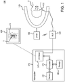
- Figure 1 is a diagram of an example system 100 for performing a facial registration.
- the system includes a registration probe 110, a magnetic field emitter 120, a hub 130, a workstation 140, a display 150, and a magnetic driver 160.
- the registration probe 110 and the magnetic field emitter 120 may also be connected to the hub 130 via the magnetic driver 160, which is connected to the workstation 140, and receives the signals from both the registration probe 110 and the magnetic emitter 120 to transfer to the workstation 140.
- the registration probe 110 and the magnetic driver 160 may be in direct communication with the workstation 140, exclusive of a signal traversing through the hub 130.
- the workstation 140 includes, for example, a processor 141, a memory 142, an input/output (I/O) driver 143, and storage 144, which allow the workstation 140 to receive input data and output data via the I/O driver 143, and store data in the storage 144 and/or memory 143 as needed for processing.
- the workstation 140 is also connected to the display 150.
- the driver 160 is connected to the magnetic emitter 120 to emit one or more magnetic fields around a patient's head H. As can be seen on the display 150, an image S is displayed that has a target T on it.
- the target T indicates a current location of the registration probe 110 in space with respect to the patient's head H.
- the location of the magnetic field emitter 120 is shown for example purposes and the emitter 120 could be located in additional areas to provide a magnetic image.
- a portion of the emitter 120 could be located beneath the patient's head H, and may include a plurality of magnetic field generators to increase the accuracy of the location.
- the registration probe would be configured to register a plurality of magnetic fields.
- the registration probe 110 includes components to allow it to be accurately located with respect to the patient's head H, and more particularly to the patient's face.
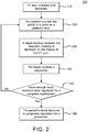
- FIG. 2 is a flow diagram of an example conventional method 200 for performing a facial registration.
- a CT scan is loaded and displayed.
- a CT scan file that has been captured previously and loaded onto a memory device or electronically sent is loaded into the workstation 140 and displayed on the display 150 as image S.
- an operator touches the registration probe to a reference point on the patient's face to register that target location on the image (step 220). For example, the operator touches registration probe 110 to an area of the patient's face depicted in the display 150 of Figure 1 .
- a target location between the magnetic modality is displayed on the CT scan (step 230). That is, the location that the coils 113 determine the registration probe 110 exists in three-dimensional space based on the magnetic field or fields received from the magnetic emitter 120 are displayed as a target location on the CT scan. This target location is then registered (step 240). This may be accomplished by the registration probe 110 transmitting its location information to the workstation 140 based on the detected magnetic fields by the coils 113, where the workstation 140 processes the location and determines where to overlay the location on the displayed image.
- step 250 If enough facial locations have been registered for a complete registration (step 250), then the patient's facial structure is completely registered for the conventional procedure (step 260). If there are not enough locations registered in step 250, then the method returns to step 220, where the operator continues to touch other areas of the patient's face in order to cover a significant enough portion of the patient's face to completely register the patient's face for the ENT procedure.
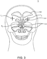
- Figure 3 is an example facial image for use during the facial registration method of Figure 2 .
- the facial image in Figure 3 may be image S from Figure 1 .
- targets T (designated T 1 , T 2 , and T 3 ) are shown as solid crosshairs.
- Target T 1 corresponds to a first point on the patient's face touched by the operator
- target T 2 corresponds to a second point on the patient's face touched by the operator
- target T 3 corresponds to a third point on the patient's face touched by the operator.
- a number of nasal cavities 310 can also be seen in the image S as depicted in Figure 3 .
- Figure 4A is a diagram 400A of an example registration probe 110 and an example registration actuation device 410 for use in the system of Figure 1 .
- Figure 4B is a diagram 400B of the example registration probe 110 and example registration actuation device 410 of Figure 4A connected together.
- the registration probe 110 includes a recessed area including a registration activation button R, which activates the components in the registration probe 110, (e.g., coils that receive the magnetic fields emitted by the emitter 120).
- the registration activation device 410 includes a connector 411 and a sensor unit 412.
- a wire W connects the device 410 to the workstation 140, (e.g., via the hub 130) to transmit data to and from the device 410 and workstation 140.
- the device 410 is placed on the registration probe 110 along the arrow C to attach it to the registration probe 110.
- the connected registration probe 110 and registration activation device 410 are shown in Figure 4B .
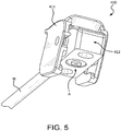
- FIG. 5 is a bottom perspective view of the registration actuation device 410 of Figures 4A and 4B .
- the bottom of the sensor unit 412 includes an actuator A.
- Actuator A coincides with the registration activation button R such that when the connector 411 is depressed, actuator A activates activation button R as well as causes a signal to be transmitted to the workstation 140 along wire W for use in the method described below.
- FIG 6 is a flow diagram of an example method 600 for performing a facial registration with example registration probe 110 and example registration actuation device 410 of Figures 4A and 4B .
- the operator selects a registration target location and touches the patient's face at that target location. For example, referring back to Figure 3 , the operator may select target location T 1 for registration.
- the operator then depresses the actuator, (e.g., actuator A of device 410), in step 620, which indicates to the system 100 that the location T 1 is being registered as a target location. If the target location registration is not complete (step 630), then the operator continues to depress the actuator until the registration is complete for that target location (step 640).
- the actuator e.g., actuator A of device 410
- step 630 If the registration at that target location is complete (step 630), then the operator releases the actuator (step 650), which indicates to the system 100 that registration in that target location has been registered.
- step 660 it is determined if the facial recognition is completed. If it is not, then the method reverts to step 610, where additional target locations are registered, (e.g., T 2 , T 3 , and so forth). If the facial registration is complete in step 660, then the operator indicates the end of registration (step 670), such as by double-clicking the actuator, for example.
- the registration probe (e.g., registration probe 110), as well as other components in the system in communication with one another may be in wired or wireless communication. That is, transceivers and antennas may be included in the devices, (e.g., registration probe 110 and other components of system 100), that can transmit and receive data wirelessly to one another.
- the registration actuation device 410 can be utilized to signal to the system 100 that a tool, such as described above, is being connected or disconnected to the system by utilizing the actuator A.
- processors include, by way of example, a general purpose processor, a special purpose processor, a conventional processor, a digital signal processor (DSP), a plurality of microprocessors, one or more microprocessors in association with a DSP core, a controller, a microcontroller, Application Specific Integrated Circuits (ASICs), Field Programmable Gate Arrays (FPGAs) circuits, any other type of integrated circuit (IC), and/or a state machine.
- DSP digital signal processor
- ASICs Application Specific Integrated Circuits
- FPGAs Field Programmable Gate Arrays
- Such processors can be manufactured by configuring a manufacturing process using the results of processed hardware description language (HDL) instructions and other intermediary data including netlists (such instructions capable of being stored on a computer readable media). The results of such processing can be maskworks that are then used in a semiconductor manufacturing process to manufacture a processor which implements features of the disclosure.
- HDL hardware description language
- non-transitory computer-readable storage mediums include a read only memory (ROM), a random access memory (RAM), a register, cache memory, semiconductor memory devices, magnetic media such as internal hard disks and removable disks, magneto-optical media, and optical media such as CD-ROM disks, and digital versatile disks (DVDs).
- ROM read only memory
- RAM random access memory
- register cache memory
- semiconductor memory devices magnetic media such as internal hard disks and removable disks, magneto-optical media, and optical media such as CD-ROM disks, and digital versatile disks (DVDs).
Landscapes
- Engineering & Computer Science (AREA)
- Health & Medical Sciences (AREA)
- Life Sciences & Earth Sciences (AREA)
- Surgery (AREA)
- Physics & Mathematics (AREA)
- General Health & Medical Sciences (AREA)
- Animal Behavior & Ethology (AREA)
- Molecular Biology (AREA)
- Medical Informatics (AREA)
- Heart & Thoracic Surgery (AREA)
- Veterinary Medicine (AREA)
- Biomedical Technology (AREA)
- Public Health (AREA)
- Human Computer Interaction (AREA)
- Nuclear Medicine, Radiotherapy & Molecular Imaging (AREA)
- Theoretical Computer Science (AREA)
- General Physics & Mathematics (AREA)
- Computer Vision & Pattern Recognition (AREA)
- Biophysics (AREA)
- Robotics (AREA)
- Pathology (AREA)
- Gynecology & Obstetrics (AREA)
- Radiology & Medical Imaging (AREA)
- Multimedia (AREA)
- Oral & Maxillofacial Surgery (AREA)
- Apparatus For Radiation Diagnosis (AREA)
- Ultra Sonic Daignosis Equipment (AREA)
- Magnetic Resonance Imaging Apparatus (AREA)
- Surgical Instruments (AREA)
Abstract
Description
- A method for performing a facial recognition is disclosed. The method includes selecting a plurality of target locations for registration. Registration takes place at each of the plurality of target locations, and is complete at each of the plurality of target locations as each target location is registered. Once the registration of all target locations is complete, it is indicated to the system.
- A system for performing facial recognition is disclosed. The system includes a workstation, a display in communication with the workstation, a magnetic emitter located proximate to the face of a patient, and a registration probe in communication with the workstation. The registration probe includes an actuator and a magnetic wave receiver that receives a magnetic signal from the magnetic emitter to identify a location in space of the registration probe relative to the magnetic emitter. The registration probe indicates that registration is taking place at each of the plurality of target locations on a person's face, indicates that registration is complete at the each of the plurality of target locations as each target location is registered, and indicates that the facial registration of all target locations is complete.
- A registration probe for performing facial recognition is disclosed. The registration probe includes a magnetic wave receiver that receives a magnetic signal from a magnetic emitter located proximate to the face of the patient to identify a location in space of the registration probe relative to the magnetic emitter, and an actuator. The registration probe indicates that registration is taking place at each of the plurality of target locations on a person's face, indicates that registration is complete at the each of the plurality of target locations as each target location is registered, and indicates that the facial registration of all target locations is complete.
- A more detailed understanding may be had from the following description, given by way of example in conjunction with the accompanying drawings wherein:
-
Figure 1 is a diagram of an example system for performing a facial registration; -
Figure 2 is a flow diagram of an example conventional method for performing a facial registration; -
Figure 3 is an example facial image for use during the facial registration method ofFigure 2 ; -
Figure 4A is a diagram of an example registration probe and example registration actuation device for use in the system ofFigure 1 ; -
Figure 4B is a diagram of the example registration probe and example registration actuation device ofFigure 4A connected together; -
Figure 5 is an underneath perspective view of the registration actuation device ofFigures 4A and4B ; and -
Figure 6 is a flow diagram of an example method for performing a facial registration with example registration probe and example registration actuation device ofFigures 4A and4B . - The present application is related to a method and apparatus for performing a facial recognition. In particular, the present application is directed to a method and apparatus for performing a facial recognition for an ear/nose/throat (ENT) procedure, such as a nasal dilation.
- In general, a person typically has eight or so sinus openings, (e.g., the frontal, anterior ethmoidal, maxillary, and middle ethmoidal, for each side), although the number of openings varies from person to person. Each of those sinus openings include areas that are very small in diameter. Accordingly, when an opening becomes clogged for one reason or another, no drainage may occur from within the sinuses. In this case, problems can occur. For example, an accumulation of mucus can cause various health issues such as infections.
- In order to treat these problems, a medical procedure such as sinus dilation may be used. Sinus dilation is a technique for increasing the size of the sinus passageway to provide a more unrestricted flow of fluids to alleviate sinus congestion. Sinus dilation is performed by using a tool that is inserted into the sinus cavity that includes a balloon which can be inflated. The balloon is inserted into the middle of the small sinus opening and dilated. This dilation applies pressure on the sinus opening to widen it (e.g., by reshaping the tissue structure of the sinus cavity). The opening remains at this increased size once the balloon is taken out, thus providing a larger passageway for fluid flow.
- To perform the nasal dilation procedure, or any ENT procedure that is similar, it is important that the physician performing the procedure know the location of the tool within the nasal cavity with a great degree of accuracy. The physician views an image of the patient's nasal cavities on a display screen and navigates within the patient's actual cavities by manipulating the tool, while looking at an image of the location of the tool on the screen. Any inaccuracies regarding the location of the tool within a patient's nasal cavity may cause the physician to damage the nasal cavity and/or to perform the procedure in the wrong place within the cavity. Therefore, it is very important that the location of the tool on the screen coincides accurately to where the actual tool is within the actual nasal cavity of the patient.
- In order to ensure that the physician knows, with accuracy, the location within the nasal cavity where he or she is performing the procedure, a registration procedure is performed. The registration procedure allows the physician to view the image that is on the display screen and register locations on a patient's face in that image. Although a system, apparatus and method are described in more detail below for performing a registration, briefly the image that is displayed, for example, is from a computerized tomography (CT) scan that is taken of the patient's head area prior to the ENT procedure. The registration is then performed by an operator, (e.g., physician or other technician), using a registration probe that is placed on various locations of a patient's face. Furthermore, the patient's head is situated in a magnetic field. The registration probe's location is registered on the CT scan that is displayed.
- Conventional registration techniques include the operator touching the registration probe to different areas on the patient's face. However, conventional registration techniques do not provide a convenient way for the operator to connect and disconnect the registration probe at each location being registered as a target location, or to indicate when registration is complete.
- Accordingly, described herein is a method, apparatus and system for performing a facial registration. The facial registration is performed by an operator who is able to connect and disconnect the registration tool from the registration system. In addition, the operator may indicate when the registration process is complete.
-
Figure 1 is a diagram of anexample system 100 for performing a facial registration. The system includes aregistration probe 110, amagnetic field emitter 120, ahub 130, aworkstation 140, adisplay 150, and amagnetic driver 160. Theregistration probe 110 and themagnetic field emitter 120 may also be connected to thehub 130 via themagnetic driver 160, which is connected to theworkstation 140, and receives the signals from both theregistration probe 110 and themagnetic emitter 120 to transfer to theworkstation 140. However, theregistration probe 110 and themagnetic driver 160 may be in direct communication with theworkstation 140, exclusive of a signal traversing through thehub 130. - The
workstation 140 includes, for example, aprocessor 141, amemory 142, an input/output (I/O)driver 143, andstorage 144, which allow theworkstation 140 to receive input data and output data via the I/O driver 143, and store data in thestorage 144 and/ormemory 143 as needed for processing. Theworkstation 140 is also connected to thedisplay 150. Thedriver 160 is connected to themagnetic emitter 120 to emit one or more magnetic fields around a patient's head H. As can be seen on thedisplay 150, an image S is displayed that has a target T on it. The target T indicates a current location of theregistration probe 110 in space with respect to the patient's head H. An operator can then see the target on the image S and register areas of the patient's face on the image S for later use in an ENT procedure. It should be noted that the location of themagnetic field emitter 120 is shown for example purposes and theemitter 120 could be located in additional areas to provide a magnetic image. For example, a portion of theemitter 120 could be located beneath the patient's head H, and may include a plurality of magnetic field generators to increase the accuracy of the location. In the case where a plurality of field generators are utilized, the registration probe would be configured to register a plurality of magnetic fields. - To perform a registration, the
registration probe 110 includes components to allow it to be accurately located with respect to the patient's head H, and more particularly to the patient's face. -
Figure 2 is a flow diagram of an exampleconventional method 200 for performing a facial registration. Instep 210, a CT scan is loaded and displayed. For example, referring back toFigure 1 , a CT scan file that has been captured previously and loaded onto a memory device or electronically sent is loaded into theworkstation 140 and displayed on thedisplay 150 as image S. - Once the image is displayed, an operator touches the registration probe to a reference point on the patient's face to register that target location on the image (step 220). For example, the operator touches
registration probe 110 to an area of the patient's face depicted in thedisplay 150 ofFigure 1 . - A target location between the magnetic modality is displayed on the CT scan (step 230). That is, the location that the coils 113 determine the
registration probe 110 exists in three-dimensional space based on the magnetic field or fields received from themagnetic emitter 120 are displayed as a target location on the CT scan. This target location is then registered (step 240). This may be accomplished by theregistration probe 110 transmitting its location information to theworkstation 140 based on the detected magnetic fields by the coils 113, where theworkstation 140 processes the location and determines where to overlay the location on the displayed image. - If enough facial locations have been registered for a complete registration (step 250), then the patient's facial structure is completely registered for the conventional procedure (step 260). If there are not enough locations registered in
step 250, then the method returns to step 220, where the operator continues to touch other areas of the patient's face in order to cover a significant enough portion of the patient's face to completely register the patient's face for the ENT procedure. -
Figure 3 is an example facial image for use during the facial registration method ofFigure 2 . For purposes of example, the facial image inFigure 3 may be image S fromFigure 1 . As can be seen inFigure 3 , targets T (designated T1, T2, and T3) are shown as solid crosshairs. Referring back to step 220 ofmethod 200, Target T1 corresponds to a first point on the patient's face touched by the operator, target T2 corresponds to a second point on the patient's face touched by the operator, and target T3 corresponds to a third point on the patient's face touched by the operator. A number ofnasal cavities 310 can also be seen in the image S as depicted inFigure 3 . - However, it would be beneficial in having an enhanced registration capability by providing the physician the ability to indicate when a target on the patient's face is being touched, (e.g., by clicking and releasing a button), and when registration is complete and no further targets on a patient's face will be registered. In addition, physicians work with a number of devices when performing an ENT procedure and it would be beneficial to provide an improved an actuation device that signals to the
system 100 that a particular tool, (e.g., registration probe suction tool, pointer, blade, navigation device, ultrasonic tip or other interchangeable probe), is being connected or disconnected to thesystem 100. -
Figure 4A is a diagram 400A of anexample registration probe 110 and an exampleregistration actuation device 410 for use in the system ofFigure 1 .Figure 4B is a diagram 400B of theexample registration probe 110 and exampleregistration actuation device 410 ofFigure 4A connected together. Theregistration probe 110 includes a recessed area including a registration activation button R, which activates the components in theregistration probe 110, (e.g., coils that receive the magnetic fields emitted by the emitter 120). - Continuing to refer to
Figures 4A and4B , theregistration activation device 410 includes aconnector 411 and asensor unit 412. A wire W connects thedevice 410 to theworkstation 140, (e.g., via the hub 130) to transmit data to and from thedevice 410 andworkstation 140. Thedevice 410 is placed on theregistration probe 110 along the arrow C to attach it to theregistration probe 110. The connectedregistration probe 110 andregistration activation device 410 are shown inFigure 4B . -
Figure 5 is a bottom perspective view of theregistration actuation device 410 ofFigures 4A and4B . As shown inFigure 5 , the bottom of thesensor unit 412 includes an actuator A. Actuator A coincides with the registration activation button R such that when theconnector 411 is depressed, actuator A activates activation button R as well as causes a signal to be transmitted to theworkstation 140 along wire W for use in the method described below. -
Figure 6 is a flow diagram of anexample method 600 for performing a facial registration withexample registration probe 110 and exampleregistration actuation device 410 ofFigures 4A and4B . Instep 610, the operator selects a registration target location and touches the patient's face at that target location. For example, referring back toFigure 3 , the operator may select target location T1 for registration. The operator then depresses the actuator, (e.g., actuator A of device 410), instep 620, which indicates to thesystem 100 that the location T1 is being registered as a target location. If the target location registration is not complete (step 630), then the operator continues to depress the actuator until the registration is complete for that target location (step 640). - If the registration at that target location is complete (step 630), then the operator releases the actuator (step 650), which indicates to the
system 100 that registration in that target location has been registered. Instep 660 then, it is determined if the facial recognition is completed. If it is not, then the method reverts to step 610, where additional target locations are registered, (e.g., T2, T3, and so forth). If the facial registration is complete instep 660, then the operator indicates the end of registration (step 670), such as by double-clicking the actuator, for example. - It should be noted that the method, apparatus and system described above can include additional modifications. For example, the registration probe, (e.g., registration probe 110), as well as other components in the system in communication with one another may be in wired or wireless communication. That is, transceivers and antennas may be included in the devices, (e.g.,
registration probe 110 and other components of system 100), that can transmit and receive data wirelessly to one another. It should also be noted that theregistration actuation device 410 can be utilized to signal to thesystem 100 that a tool, such as described above, is being connected or disconnected to the system by utilizing the actuator A. - The methods provided can be implemented in a general purpose computer, a processor, or a processor core. Suitable processors include, by way of example, a general purpose processor, a special purpose processor, a conventional processor, a digital signal processor (DSP), a plurality of microprocessors, one or more microprocessors in association with a DSP core, a controller, a microcontroller, Application Specific Integrated Circuits (ASICs), Field Programmable Gate Arrays (FPGAs) circuits, any other type of integrated circuit (IC), and/or a state machine. Such processors can be manufactured by configuring a manufacturing process using the results of processed hardware description language (HDL) instructions and other intermediary data including netlists (such instructions capable of being stored on a computer readable media). The results of such processing can be maskworks that are then used in a semiconductor manufacturing process to manufacture a processor which implements features of the disclosure.
- The methods or flow charts provided herein can be implemented in a computer program, software, or firmware incorporated in a non-transitory computer-readable storage medium for execution by a general purpose computer or a processor. Examples of non-transitory computer-readable storage mediums include a read only memory (ROM), a random access memory (RAM), a register, cache memory, semiconductor memory devices, magnetic media such as internal hard disks and removable disks, magneto-optical media, and optical media such as CD-ROM disks, and digital versatile disks (DVDs).
Claims (18)
- A method for performing facial registration using a registration probe, comprising:selecting a plurality of target locations for registration;indicating, with the registration probe, that registration is taking place at each of the plurality of target locations;indicating, with the registration probe, that registration is complete at the each of the plurality of target locations as each target location is registered; andindicating, with the registration probe, that the facial registration of all target locations is complete.
- The method of claim 1 wherein the indicating that registration is to take place at each of the plurality of target locations includes depressing an actuator on the registration probe.
- The method of claim 2 wherein the indicating that registration is complete at the each of the plurality of target locations as each target location is registered includes releasing the actuator.
- The method of claim 1 wherein the indicating that the facial registration of all target locations is complete includes multiple depressing of an actuator.
- The method of claim 1 wherein upon indicating that registration is complete at one of the plurality of target locations, the target location is registered on a computerized tomography (CT) scan.
- The method of claim 5 wherein upon indicating that the facial registration of all target locations is complete, all target locations are registered.
- A system for performing facial recognition, comprising:a workstation;a display in communication with the workstation;a magnetic emitter located proximate to the face of a patient; anda registration probe in communication with the workstation, the registration probe including an actuator and a magnetic wave receiver that receives a magnetic signal from the magnetic emitter to identify a location in space of the registration probe relative to the magnetic emitter, the registration probe configured to:indicate that registration is taking place at each of the plurality of target locations on a person's face;indicate that registration is complete at the each of the plurality of target locations as each target location is registered; andindicate that the facial registration of all target locations is complete.
- The system of claim 7 wherein the workstation transmits the correlated target locations to the display for display on the reference image of the face of the patient.
- The system of claim 8 wherein the reference image is a computerized tomography (CT) scan of the face of the patient.
- The system of claim 7 wherein the registration probe and the workstation are in wireless communication with one another.
- The apparatus of claim 7, further comprising a hub device in communication with the registration probe and the workstation for effectuating communication between the registration probe and the workstation.
- The apparatus of claim 11 wherein the hub is in communication with a driver that drives the magnetic emitter.
- The system of claim 7 wherein the workstation further comprises a processor, a memory and a storage component in communication with one another, and wherein a reference image is stored in the memory of the workstation for transmission to the display.
- The system of claim 7 wherein the magnetic receiver is a coil disposed in the registration probe for receiving the magnetic wave.
- A registration probe in communication with a facial recognition system, comprising:a magnetic wave receiver that receives a magnetic signal from a magnetic emitter located proximate to the face of the patient to identify a location in space of the registration probe relative to the magnetic emitter; andan actuator,wherein the registration probe is configured to:indicate that registration is taking place at each of the plurality of target locations on a person's face;indicate that registration is complete at the each of the plurality of target locations as each target location is registered; andindicate that the facial registration of all target locations is complete.
- The system of claim 7 or the registration probe of claim 15 wherein the registration probe is configured to indicate that registration is taking place at each of the plurality of target locations on a person's face when the actuator is depressed.
- The system or the registration probe of claim 16 wherein the registration probe is configured to indicate that registration is complete at the each of the plurality of target locations as each target location is registered when the actuator is released.
- The system of claim 7 or the registration probe of claim 15 wherein the registration probe is configured to indicate indicate that the facial registration of all target locations is complete when the actuator is depressed multiple times.
Applications Claiming Priority (1)
| Application Number | Priority Date | Filing Date | Title |
|---|---|---|---|
| US16/212,060 US11481909B2 (en) | 2018-12-06 | 2018-12-06 | Method and apparatus for performing facial registration |
Publications (2)
| Publication Number | Publication Date |
|---|---|
| EP3662828A1 true EP3662828A1 (en) | 2020-06-10 |
| EP3662828B1 EP3662828B1 (en) | 2022-03-30 |
Family
ID=68806593
Family Applications (1)
| Application Number | Title | Priority Date | Filing Date |
|---|---|---|---|
| EP19213718.0A Active EP3662828B1 (en) | 2018-12-06 | 2019-12-05 | Method and apparatus for performing facial registration |
Country Status (5)
| Country | Link |
|---|---|
| US (1) | US11481909B2 (en) |
| EP (1) | EP3662828B1 (en) |
| JP (1) | JP7412992B2 (en) |
| CN (1) | CN111281539B (en) |
| IL (1) | IL270517B2 (en) |
Families Citing this family (2)
| Publication number | Priority date | Publication date | Assignee | Title |
|---|---|---|---|---|
| JP2021145881A (en) * | 2020-03-18 | 2021-09-27 | 国立大学法人福井大学 | Image processing method, image composition method, acquisition method of data, generation method of learning model, diagnosis support system of nose and paranasal sinus disease and diagnosis support method of nose and paranasal sinus disease |
| US12611258B2 (en) * | 2021-05-20 | 2026-04-28 | Acclarent, Inc. | Registration probe for enhanced information capture |
Citations (2)
| Publication number | Priority date | Publication date | Assignee | Title |
|---|---|---|---|---|
| US20170020411A1 (en) * | 2015-07-23 | 2017-01-26 | Biosense Webster (Israel) Ltd. | Surface Registration of a CT Image with a Magnetic Tracking System |
| EP3292835A1 (en) * | 2016-09-08 | 2018-03-14 | Biosense Webster (Israel) Ltd. | Ent image registration |
Family Cites Families (18)
| Publication number | Priority date | Publication date | Assignee | Title |
|---|---|---|---|---|
| US5503320A (en) | 1993-08-19 | 1996-04-02 | United States Surgical Corporation | Surgical apparatus with indicator |
| US6139214A (en) | 1998-12-14 | 2000-10-31 | Endius Incorporated | Quick disconnect coupling for surgical instrument |
| US6312434B1 (en) * | 1999-04-14 | 2001-11-06 | Northgate Technologies, Inc. | Device for producing a shock wave to impact an object |
| JP2002304584A (en) | 2001-04-05 | 2002-10-18 | Olympus Optical Co Ltd | Equipment rental system |
| US20070208252A1 (en) | 2004-04-21 | 2007-09-06 | Acclarent, Inc. | Systems and methods for performing image guided procedures within the ear, nose, throat and paranasal sinuses |
| US8491503B2 (en) | 2004-09-29 | 2013-07-23 | Covidien Lp | Intrauterine pressure catheter interface cable system |
| US7693349B2 (en) | 2006-08-15 | 2010-04-06 | General Electric Company | Systems and methods for interactive image registration |
| US7995819B2 (en) | 2006-10-30 | 2011-08-09 | General Electric Company | Methods for displaying a location of a point of interest on a 3-D model of an anatomical region |
| US10751509B2 (en) * | 2007-11-26 | 2020-08-25 | C. R. Bard, Inc. | Iconic representations for guidance of an indwelling medical device |
| WO2011074672A1 (en) * | 2009-12-18 | 2011-06-23 | 株式会社小松製作所 | Work vehicle monitoring device |
| US20180325610A1 (en) * | 2012-06-21 | 2018-11-15 | Globus Medical, Inc. | Methods for indicating and confirming a point of interest using surgical navigation systems |
| WO2014139022A1 (en) * | 2013-03-15 | 2014-09-18 | Synaptive Medical (Barbados) Inc. | Systems and methods for navigation and simulation of minimally invasive therapy |
| US10463242B2 (en) * | 2014-07-09 | 2019-11-05 | Acclarent, Inc. | Guidewire navigation for sinuplasty |
| US11191593B2 (en) * | 2014-09-30 | 2021-12-07 | Koninklijke Philips N.V. | Triggering with optical shape sensing fiber |
| CA2973479C (en) * | 2015-07-21 | 2019-02-26 | Synaptive Medical (Barbados) Inc. | System and method for mapping navigation space to patient space in a medical procedure |
| US10152786B2 (en) * | 2016-10-11 | 2018-12-11 | Biosense Webster (Israel) Ltd. | Registration of a magnetic tracking system with an imaging device |
| US11937880B2 (en) * | 2017-04-18 | 2024-03-26 | Intuitive Surgical Operations, Inc. | Graphical user interface for monitoring an image-guided procedure |
| US10786311B2 (en) * | 2017-12-22 | 2020-09-29 | Acclarent, Inc. | Apparatus and method for registering facial landmarks for surgical navigation system |
-
2018
- 2018-12-06 US US16/212,060 patent/US11481909B2/en active Active
-
2019
- 2019-11-07 IL IL270517A patent/IL270517B2/en unknown
- 2019-12-05 JP JP2019220120A patent/JP7412992B2/en active Active
- 2019-12-05 EP EP19213718.0A patent/EP3662828B1/en active Active
- 2019-12-06 CN CN201911240928.6A patent/CN111281539B/en active Active
Patent Citations (2)
| Publication number | Priority date | Publication date | Assignee | Title |
|---|---|---|---|---|
| US20170020411A1 (en) * | 2015-07-23 | 2017-01-26 | Biosense Webster (Israel) Ltd. | Surface Registration of a CT Image with a Magnetic Tracking System |
| EP3292835A1 (en) * | 2016-09-08 | 2018-03-14 | Biosense Webster (Israel) Ltd. | Ent image registration |
Also Published As
| Publication number | Publication date |
|---|---|
| JP7412992B2 (en) | 2024-01-15 |
| IL270517B1 (en) | 2024-03-01 |
| CN111281539A (en) | 2020-06-16 |
| JP2020089732A (en) | 2020-06-11 |
| IL270517B2 (en) | 2024-07-01 |
| IL270517A (en) | 2020-06-30 |
| EP3662828B1 (en) | 2022-03-30 |
| CN111281539B (en) | 2025-01-03 |
| US11481909B2 (en) | 2022-10-25 |
| US20200184661A1 (en) | 2020-06-11 |
Similar Documents
| Publication | Publication Date | Title |
|---|---|---|
| US11419685B2 (en) | Apparatus and method for registering facial landmarks for surgical navigation system | |
| CN106456135B (en) | medical system | |
| US20160354152A1 (en) | Accurate Three-Dimensional Instrument Positioning | |
| CN107913102A (en) | Anatomic image and the positioning control system carried out using ultrasound it is preoperative registering | |
| EP3662828B1 (en) | Method and apparatus for performing facial registration | |
| CN114432573A (en) | Medical Device Systems and Medical Device Insertion Systems | |
| CN119313603A (en) | Systems and methods for suggesting catheter parameters | |
| WO2023006070A1 (en) | Interventional navigation system | |
| US20230329805A1 (en) | Pointer tool for endoscopic surgical procedures | |
| JP2020089732A5 (en) | ||
| EP3454299B1 (en) | Method and apparatus for performing facial registration | |
| CN113164067A (en) | System for visualizing patient pressure | |
| US20190046154A1 (en) | Method and apparatus for performing facial registration | |
| US11065064B2 (en) | Calibration of a rigid ENT tool | |
| US20190046155A1 (en) | Method and apparatus for performing facial registration | |
| WO2023144668A1 (en) | Customized patient tracker for image guided surgery | |
| JP7331087B2 (en) | birth magnetic tracking system | |
| CN115398476A (en) | Preoperative registration of anatomical images with a position tracking system using ultrasound measurements of skin tissue | |
| US20250339969A1 (en) | Robotic calibration | |
| US20230233097A1 (en) | Customized patient tracker for image guided surgery | |
| CN211432985U (en) | High-precision positioning device | |
| CN116687450A (en) | Ultrasound Imaging System |
Legal Events
| Date | Code | Title | Description |
|---|---|---|---|
| PUAI | Public reference made under article 153(3) epc to a published international application that has entered the european phase |
Free format text: ORIGINAL CODE: 0009012 |
|
| STAA | Information on the status of an ep patent application or granted ep patent |
Free format text: STATUS: THE APPLICATION HAS BEEN PUBLISHED |
|
| AK | Designated contracting states |
Kind code of ref document: A1 Designated state(s): AL AT BE BG CH CY CZ DE DK EE ES FI FR GB GR HR HU IE IS IT LI LT LU LV MC MK MT NL NO PL PT RO RS SE SI SK SM TR |
|
| AX | Request for extension of the european patent |
Extension state: BA ME |
|
| STAA | Information on the status of an ep patent application or granted ep patent |
Free format text: STATUS: REQUEST FOR EXAMINATION WAS MADE |
|
| 17P | Request for examination filed |
Effective date: 20201209 |
|
| RBV | Designated contracting states (corrected) |
Designated state(s): AL AT BE BG CH CY CZ DE DK EE ES FI FR GB GR HR HU IE IS IT LI LT LU LV MC MK MT NL NO PL PT RO RS SE SI SK SM TR |
|
| STAA | Information on the status of an ep patent application or granted ep patent |
Free format text: STATUS: EXAMINATION IS IN PROGRESS |
|
| 17Q | First examination report despatched |
Effective date: 20210504 |
|
| GRAP | Despatch of communication of intention to grant a patent |
Free format text: ORIGINAL CODE: EPIDOSNIGR1 |
|
| STAA | Information on the status of an ep patent application or granted ep patent |
Free format text: STATUS: GRANT OF PATENT IS INTENDED |
|
| INTG | Intention to grant announced |
Effective date: 20211206 |
|
| GRAS | Grant fee paid |
Free format text: ORIGINAL CODE: EPIDOSNIGR3 |
|
| GRAA | (expected) grant |
Free format text: ORIGINAL CODE: 0009210 |
|
| STAA | Information on the status of an ep patent application or granted ep patent |
Free format text: STATUS: THE PATENT HAS BEEN GRANTED |
|
| AK | Designated contracting states |
Kind code of ref document: B1 Designated state(s): AL AT BE BG CH CY CZ DE DK EE ES FI FR GB GR HR HU IE IS IT LI LT LU LV MC MK MT NL NO PL PT RO RS SE SI SK SM TR |
|
| REG | Reference to a national code |
Ref country code: GB Ref legal event code: FG4D |
|
| REG | Reference to a national code |
Ref country code: CH Ref legal event code: EP |
|
| REG | Reference to a national code |
Ref country code: DE Ref legal event code: R096 Ref document number: 602019013043 Country of ref document: DE |
|
| REG | Reference to a national code |
Ref country code: AT Ref legal event code: REF Ref document number: 1478461 Country of ref document: AT Kind code of ref document: T Effective date: 20220415 |
|
| REG | Reference to a national code |
Ref country code: IE Ref legal event code: FG4D |
|
| REG | Reference to a national code |
Ref country code: NL Ref legal event code: FP |
|
| REG | Reference to a national code |
Ref country code: LT Ref legal event code: MG9D |
|
| PG25 | Lapsed in a contracting state [announced via postgrant information from national office to epo] |
Ref country code: SE Free format text: LAPSE BECAUSE OF FAILURE TO SUBMIT A TRANSLATION OF THE DESCRIPTION OR TO PAY THE FEE WITHIN THE PRESCRIBED TIME-LIMIT Effective date: 20220330 Ref country code: RS Free format text: LAPSE BECAUSE OF FAILURE TO SUBMIT A TRANSLATION OF THE DESCRIPTION OR TO PAY THE FEE WITHIN THE PRESCRIBED TIME-LIMIT Effective date: 20220330 Ref country code: NO Free format text: LAPSE BECAUSE OF FAILURE TO SUBMIT A TRANSLATION OF THE DESCRIPTION OR TO PAY THE FEE WITHIN THE PRESCRIBED TIME-LIMIT Effective date: 20220630 Ref country code: LT Free format text: LAPSE BECAUSE OF FAILURE TO SUBMIT A TRANSLATION OF THE DESCRIPTION OR TO PAY THE FEE WITHIN THE PRESCRIBED TIME-LIMIT Effective date: 20220330 Ref country code: HR Free format text: LAPSE BECAUSE OF FAILURE TO SUBMIT A TRANSLATION OF THE DESCRIPTION OR TO PAY THE FEE WITHIN THE PRESCRIBED TIME-LIMIT Effective date: 20220330 Ref country code: BG Free format text: LAPSE BECAUSE OF FAILURE TO SUBMIT A TRANSLATION OF THE DESCRIPTION OR TO PAY THE FEE WITHIN THE PRESCRIBED TIME-LIMIT Effective date: 20220630 |
|
| REG | Reference to a national code |
Ref country code: AT Ref legal event code: MK05 Ref document number: 1478461 Country of ref document: AT Kind code of ref document: T Effective date: 20220330 |
|
| PG25 | Lapsed in a contracting state [announced via postgrant information from national office to epo] |
Ref country code: LV Free format text: LAPSE BECAUSE OF FAILURE TO SUBMIT A TRANSLATION OF THE DESCRIPTION OR TO PAY THE FEE WITHIN THE PRESCRIBED TIME-LIMIT Effective date: 20220330 Ref country code: GR Free format text: LAPSE BECAUSE OF FAILURE TO SUBMIT A TRANSLATION OF THE DESCRIPTION OR TO PAY THE FEE WITHIN THE PRESCRIBED TIME-LIMIT Effective date: 20220701 Ref country code: FI Free format text: LAPSE BECAUSE OF FAILURE TO SUBMIT A TRANSLATION OF THE DESCRIPTION OR TO PAY THE FEE WITHIN THE PRESCRIBED TIME-LIMIT Effective date: 20220330 |
|
| PG25 | Lapsed in a contracting state [announced via postgrant information from national office to epo] |
Ref country code: SM Free format text: LAPSE BECAUSE OF FAILURE TO SUBMIT A TRANSLATION OF THE DESCRIPTION OR TO PAY THE FEE WITHIN THE PRESCRIBED TIME-LIMIT Effective date: 20220330 Ref country code: SK Free format text: LAPSE BECAUSE OF FAILURE TO SUBMIT A TRANSLATION OF THE DESCRIPTION OR TO PAY THE FEE WITHIN THE PRESCRIBED TIME-LIMIT Effective date: 20220330 Ref country code: RO Free format text: LAPSE BECAUSE OF FAILURE TO SUBMIT A TRANSLATION OF THE DESCRIPTION OR TO PAY THE FEE WITHIN THE PRESCRIBED TIME-LIMIT Effective date: 20220330 Ref country code: PT Free format text: LAPSE BECAUSE OF FAILURE TO SUBMIT A TRANSLATION OF THE DESCRIPTION OR TO PAY THE FEE WITHIN THE PRESCRIBED TIME-LIMIT Effective date: 20220801 Ref country code: ES Free format text: LAPSE BECAUSE OF FAILURE TO SUBMIT A TRANSLATION OF THE DESCRIPTION OR TO PAY THE FEE WITHIN THE PRESCRIBED TIME-LIMIT Effective date: 20220330 Ref country code: EE Free format text: LAPSE BECAUSE OF FAILURE TO SUBMIT A TRANSLATION OF THE DESCRIPTION OR TO PAY THE FEE WITHIN THE PRESCRIBED TIME-LIMIT Effective date: 20220330 Ref country code: CZ Free format text: LAPSE BECAUSE OF FAILURE TO SUBMIT A TRANSLATION OF THE DESCRIPTION OR TO PAY THE FEE WITHIN THE PRESCRIBED TIME-LIMIT Effective date: 20220330 Ref country code: AT Free format text: LAPSE BECAUSE OF FAILURE TO SUBMIT A TRANSLATION OF THE DESCRIPTION OR TO PAY THE FEE WITHIN THE PRESCRIBED TIME-LIMIT Effective date: 20220330 |
|
| PG25 | Lapsed in a contracting state [announced via postgrant information from national office to epo] |
Ref country code: PL Free format text: LAPSE BECAUSE OF FAILURE TO SUBMIT A TRANSLATION OF THE DESCRIPTION OR TO PAY THE FEE WITHIN THE PRESCRIBED TIME-LIMIT Effective date: 20220330 Ref country code: IS Free format text: LAPSE BECAUSE OF FAILURE TO SUBMIT A TRANSLATION OF THE DESCRIPTION OR TO PAY THE FEE WITHIN THE PRESCRIBED TIME-LIMIT Effective date: 20220730 Ref country code: AL Free format text: LAPSE BECAUSE OF FAILURE TO SUBMIT A TRANSLATION OF THE DESCRIPTION OR TO PAY THE FEE WITHIN THE PRESCRIBED TIME-LIMIT Effective date: 20220330 |
|
| REG | Reference to a national code |
Ref country code: DE Ref legal event code: R097 Ref document number: 602019013043 Country of ref document: DE |
|
| PG25 | Lapsed in a contracting state [announced via postgrant information from national office to epo] |
Ref country code: DK Free format text: LAPSE BECAUSE OF FAILURE TO SUBMIT A TRANSLATION OF THE DESCRIPTION OR TO PAY THE FEE WITHIN THE PRESCRIBED TIME-LIMIT Effective date: 20220330 |
|
| PGFP | Annual fee paid to national office [announced via postgrant information from national office to epo] |
Ref country code: NL Payment date: 20221114 Year of fee payment: 4 |
|
| PLBE | No opposition filed within time limit |
Free format text: ORIGINAL CODE: 0009261 |
|
| STAA | Information on the status of an ep patent application or granted ep patent |
Free format text: STATUS: NO OPPOSITION FILED WITHIN TIME LIMIT |
|
| 26N | No opposition filed |
Effective date: 20230103 |
|
| PG25 | Lapsed in a contracting state [announced via postgrant information from national office to epo] |
Ref country code: SI Free format text: LAPSE BECAUSE OF FAILURE TO SUBMIT A TRANSLATION OF THE DESCRIPTION OR TO PAY THE FEE WITHIN THE PRESCRIBED TIME-LIMIT Effective date: 20220330 |
|
| REG | Reference to a national code |
Ref country code: CH Ref legal event code: PL |
|
| REG | Reference to a national code |
Ref country code: BE Ref legal event code: MM Effective date: 20221231 |
|
| PG25 | Lapsed in a contracting state [announced via postgrant information from national office to epo] |
Ref country code: LU Free format text: LAPSE BECAUSE OF NON-PAYMENT OF DUE FEES Effective date: 20221205 |
|
| PG25 | Lapsed in a contracting state [announced via postgrant information from national office to epo] |
Ref country code: LI Free format text: LAPSE BECAUSE OF NON-PAYMENT OF DUE FEES Effective date: 20221231 Ref country code: IE Free format text: LAPSE BECAUSE OF NON-PAYMENT OF DUE FEES Effective date: 20221205 Ref country code: CH Free format text: LAPSE BECAUSE OF NON-PAYMENT OF DUE FEES Effective date: 20221231 |
|
| PG25 | Lapsed in a contracting state [announced via postgrant information from national office to epo] |
Ref country code: BE Free format text: LAPSE BECAUSE OF NON-PAYMENT OF DUE FEES Effective date: 20221231 |
|
| PG25 | Lapsed in a contracting state [announced via postgrant information from national office to epo] |
Ref country code: HU Free format text: LAPSE BECAUSE OF FAILURE TO SUBMIT A TRANSLATION OF THE DESCRIPTION OR TO PAY THE FEE WITHIN THE PRESCRIBED TIME-LIMIT; INVALID AB INITIO Effective date: 20191205 |
|
| PG25 | Lapsed in a contracting state [announced via postgrant information from national office to epo] |
Ref country code: CY Free format text: LAPSE BECAUSE OF FAILURE TO SUBMIT A TRANSLATION OF THE DESCRIPTION OR TO PAY THE FEE WITHIN THE PRESCRIBED TIME-LIMIT Effective date: 20220330 |
|
| PG25 | Lapsed in a contracting state [announced via postgrant information from national office to epo] |
Ref country code: MK Free format text: LAPSE BECAUSE OF FAILURE TO SUBMIT A TRANSLATION OF THE DESCRIPTION OR TO PAY THE FEE WITHIN THE PRESCRIBED TIME-LIMIT Effective date: 20220330 |
|
| PG25 | Lapsed in a contracting state [announced via postgrant information from national office to epo] |
Ref country code: MC Free format text: LAPSE BECAUSE OF FAILURE TO SUBMIT A TRANSLATION OF THE DESCRIPTION OR TO PAY THE FEE WITHIN THE PRESCRIBED TIME-LIMIT Effective date: 20220330 |
|
| PG25 | Lapsed in a contracting state [announced via postgrant information from national office to epo] |
Ref country code: TR Free format text: LAPSE BECAUSE OF FAILURE TO SUBMIT A TRANSLATION OF THE DESCRIPTION OR TO PAY THE FEE WITHIN THE PRESCRIBED TIME-LIMIT Effective date: 20220330 Ref country code: MC Free format text: LAPSE BECAUSE OF FAILURE TO SUBMIT A TRANSLATION OF THE DESCRIPTION OR TO PAY THE FEE WITHIN THE PRESCRIBED TIME-LIMIT Effective date: 20220330 |
|
| REG | Reference to a national code |
Ref country code: NL Ref legal event code: MM Effective date: 20240101 |
|
| PG25 | Lapsed in a contracting state [announced via postgrant information from national office to epo] |
Ref country code: NL Free format text: LAPSE BECAUSE OF NON-PAYMENT OF DUE FEES Effective date: 20240101 |
|
| PG25 | Lapsed in a contracting state [announced via postgrant information from national office to epo] |
Ref country code: NL Free format text: LAPSE BECAUSE OF NON-PAYMENT OF DUE FEES Effective date: 20240101 Ref country code: MT Free format text: LAPSE BECAUSE OF FAILURE TO SUBMIT A TRANSLATION OF THE DESCRIPTION OR TO PAY THE FEE WITHIN THE PRESCRIBED TIME-LIMIT Effective date: 20220330 |
|
| PGFP | Annual fee paid to national office [announced via postgrant information from national office to epo] |
Ref country code: DE Payment date: 20251028 Year of fee payment: 7 |
|
| PGFP | Annual fee paid to national office [announced via postgrant information from national office to epo] |
Ref country code: GB Payment date: 20251030 Year of fee payment: 7 |
|
| PGFP | Annual fee paid to national office [announced via postgrant information from national office to epo] |
Ref country code: IT Payment date: 20251121 Year of fee payment: 7 |
|
| PGFP | Annual fee paid to national office [announced via postgrant information from national office to epo] |
Ref country code: FR Payment date: 20251110 Year of fee payment: 7 |