EP3661180A1 - System and method for providing enhanced routing in a contact center - Google Patents
System and method for providing enhanced routing in a contact center Download PDFInfo
- Publication number
- EP3661180A1 EP3661180A1 EP19211763.8A EP19211763A EP3661180A1 EP 3661180 A1 EP3661180 A1 EP 3661180A1 EP 19211763 A EP19211763 A EP 19211763A EP 3661180 A1 EP3661180 A1 EP 3661180A1
- Authority
- EP
- European Patent Office
- Prior art keywords
- communication session
- communication device
- contact center
- sensors
- external
- Prior art date
- Legal status (The legal status is an assumption and is not a legal conclusion. Google has not performed a legal analysis and makes no representation as to the accuracy of the status listed.)
- Granted
Links
Images



Classifications
-
- H—ELECTRICITY
- H04—ELECTRIC COMMUNICATION TECHNIQUE
- H04L—TRANSMISSION OF DIGITAL INFORMATION, e.g. TELEGRAPHIC COMMUNICATION
- H04L67/00—Network arrangements or protocols for supporting network services or applications
- H04L67/14—Session management
- H04L67/141—Setup of application sessions
-
- H—ELECTRICITY
- H04—ELECTRIC COMMUNICATION TECHNIQUE
- H04M—TELEPHONIC COMMUNICATION
- H04M3/00—Automatic or semi-automatic exchanges
- H04M3/42—Systems providing special services or facilities to subscribers
- H04M3/50—Centralised arrangements for answering calls; Centralised arrangements for recording messages for absent or busy subscribers ; Centralised arrangements for recording messages
- H04M3/51—Centralised call answering arrangements requiring operator intervention, e.g. call or contact centers for telemarketing
- H04M3/523—Centralised call answering arrangements requiring operator intervention, e.g. call or contact centers for telemarketing with call distribution or queueing
- H04M3/5232—Call distribution algorithms
-
- H—ELECTRICITY
- H04—ELECTRIC COMMUNICATION TECHNIQUE
- H04M—TELEPHONIC COMMUNICATION
- H04M3/00—Automatic or semi-automatic exchanges
- H04M3/42—Systems providing special services or facilities to subscribers
- H04M3/50—Centralised arrangements for answering calls; Centralised arrangements for recording messages for absent or busy subscribers ; Centralised arrangements for recording messages
- H04M3/51—Centralised call answering arrangements requiring operator intervention, e.g. call or contact centers for telemarketing
- H04M3/523—Centralised call answering arrangements requiring operator intervention, e.g. call or contact centers for telemarketing with call distribution or queueing
-
- G—PHYSICS
- G06—COMPUTING OR CALCULATING; COUNTING
- G06N—COMPUTING ARRANGEMENTS BASED ON SPECIFIC COMPUTATIONAL MODELS
- G06N20/00—Machine learning
-
- H—ELECTRICITY
- H04—ELECTRIC COMMUNICATION TECHNIQUE
- H04L—TRANSMISSION OF DIGITAL INFORMATION, e.g. TELEGRAPHIC COMMUNICATION
- H04L51/00—User-to-user messaging in packet-switching networks, transmitted according to store-and-forward or real-time protocols, e.g. e-mail
- H04L51/02—User-to-user messaging in packet-switching networks, transmitted according to store-and-forward or real-time protocols, e.g. e-mail using automatic reactions or user delegation, e.g. automatic replies or chatbot-generated messages
-
- H—ELECTRICITY
- H04—ELECTRIC COMMUNICATION TECHNIQUE
- H04L—TRANSMISSION OF DIGITAL INFORMATION, e.g. TELEGRAPHIC COMMUNICATION
- H04L67/00—Network arrangements or protocols for supporting network services or applications
- H04L67/01—Protocols
- H04L67/12—Protocols specially adapted for proprietary or special-purpose networking environments, e.g. medical networks, sensor networks, networks in vehicles or remote metering networks
-
- H—ELECTRICITY
- H04—ELECTRIC COMMUNICATION TECHNIQUE
- H04M—TELEPHONIC COMMUNICATION
- H04M3/00—Automatic or semi-automatic exchanges
- H04M3/42—Systems providing special services or facilities to subscribers
- H04M3/50—Centralised arrangements for answering calls; Centralised arrangements for recording messages for absent or busy subscribers ; Centralised arrangements for recording messages
- H04M3/51—Centralised call answering arrangements requiring operator intervention, e.g. call or contact centers for telemarketing
- H04M3/5166—Centralised call answering arrangements requiring operator intervention, e.g. call or contact centers for telemarketing in combination with interactive voice response systems or voice portals, e.g. as front-ends
-
- H—ELECTRICITY
- H04—ELECTRIC COMMUNICATION TECHNIQUE
- H04M—TELEPHONIC COMMUNICATION
- H04M3/00—Automatic or semi-automatic exchanges
- H04M3/42—Systems providing special services or facilities to subscribers
- H04M3/50—Centralised arrangements for answering calls; Centralised arrangements for recording messages for absent or busy subscribers ; Centralised arrangements for recording messages
- H04M3/51—Centralised call answering arrangements requiring operator intervention, e.g. call or contact centers for telemarketing
- H04M3/5183—Call or contact centers with computer-telephony arrangements
- H04M3/5191—Call or contact centers with computer-telephony arrangements interacting with the Internet
-
- H—ELECTRICITY
- H04—ELECTRIC COMMUNICATION TECHNIQUE
- H04M—TELEPHONIC COMMUNICATION
- H04M2250/00—Details of telephonic subscriber devices
- H04M2250/12—Details of telephonic subscriber devices including a sensor for measuring a physical value, e.g. temperature or motion
Definitions
- the disclosure relates generally to contact centers and particularly to systems and methods for routing communication sessions in a contact center.
- An Internet of Things is a network of physical devices with sensors, such as, vehicles, home appliances, medical devices, and other network elements embedded with electronics, software, sensors, actuators, etc. These devices enable IoT devices to connect and exchange data, which creates opportunities for more direct integration of the physical world into computer-based systems. This can result in efficiency improvements, economic benefits, and reduced human exertions (See https://en.wikipedia.org/wiki/Internet of things)
- contact centers monitor and respond to events. Attributes are used to provide optimal matching of customers, agents, and other resources in the contact center where the events are handled by humans and bots.
- One area that is evolving is the automation of event reporting and management that does not require a human user to contact the contact center directly.
- the contact centers of today fail to leverage the full capabilities of using IoT devices to provide an enhanced contact center experience.
- a first request to establish a communication session with a contact center is received from a user communication device. For example, a request to establish a voice communication session is received at the contact center.
- a machine learning model uses prior communication sessions with the contact center to identify a first set of one or more sensors that are external to the user communication device. External sensor information is received (e.g., during the request to establish the communication session) by the contact center. The external sensor information is from the first set of one or more sensors that are external to the user communication device.
- the communication session in the contact center is routed based on the received external sensor information. For example, instead of the communication session being routed to an Interactive Voice Response (IVR) system, the communication session is routed to a high priority contact center queue.
- IVR Interactive Voice Response
- each of the expressions “at least one of A, B and C”, “at least one of A, B, or C”, “one or more of A, B, and C", “one or more of A, B, or C", "A, B, and/or C", and "A, B, or C” means A alone, B alone, C alone, A and B together, A and C together, B and C together, or A, B and C together.
- automated refers to any process or operation, which is typically continuous or semi-continuous, done without material human input when the process or operation is performed.
- a process or operation can be automatic, even though performance of the process or operation uses material or immaterial human input, if the input is received before performance of the process or operation.
- Human input is deemed to be material if such input influences how the process or operation will be performed. Human input that consents to the performance of the process or operation is not deemed to be "material”.
- aspects of the present disclosure may take the form of an entirely hardware embodiment, an entirely software embodiment (including firmware, resident software, micro-code, etc.) or an embodiment combining software and hardware aspects that may all generally be referred to herein as a "circuit,” “module” or “system.” Any combination of one or more computer readable medium(s) may be utilized.
- the computer readable medium may be a computer readable signal medium or a computer readable storage medium.
- a computer readable storage medium may be, for example, but not limited to, an electronic, magnetic, optical, electromagnetic, infrared, or semiconductor system, apparatus, or device, or any suitable combination of the foregoing. More specific examples (a non-exhaustive list) of the computer readable storage medium would include the following: an electrical connection having one or more wires, a portable computer diskette, a hard disk, a random access memory (RAM), a read-only memory (ROM), an erasable programmable read-only memory (EPROM or Flash memory), an optical fiber, a portable compact disc read-only memory (CD-ROM), an optical storage device, a magnetic storage device, or any suitable combination of the foregoing.
- a computer readable storage medium may be any tangible medium that can contain, or store a program for use by or in connection with an instruction execution system, apparatus, or device.
- a computer readable signal medium may include a propagated data signal with computer readable program code embodied therein, for example, in baseband or as part of a carrier wave. Such a propagated signal may take any of a variety of forms, including, but not limited to, electro-magnetic, optical, or any suitable combination thereof.
- a computer readable signal medium may be any computer readable medium that is not a computer readable storage medium and that can communicate, propagate, or transport a program for use by or in connection with an instruction execution system, apparatus, or device.
- Program code embodied on a computer readable medium may be transmitted using any appropriate medium, including but not limited to wireless, wireline, optical fiber cable, RF, etc., or any suitable combination of the foregoing.
- SIP Session Initiation Protocol
- IP Internet Protocol
- the protocol can be used for creating, modifying and terminating two-party (unicast) or multiparty (multicast) sessions consisting of one or several media streams. The modification can involve changing addresses or ports, inviting more participants, and adding or deleting media streams.
- Other feasible application examples include video conferencing, streaming multimedia distribution, instant messaging, presence information, file transfer and online games.
- SIP is as described in RFC 3261, available from the Internet Engineering Task Force (IETF) Network Working Group, November 2000 ; this document and all other SIP RFCs describing SIP are hereby incorporated by reference in their entirety for all that they teach.
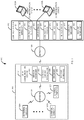
- Fig. 1 is a block diagram of a first illustrative system 100 for providing enhanced routing in a contact center 120.
- the first illustrative system 100 comprises a user communication device 101, external sensors 106A-106N, control element(s) 107, a location 108, networks 110A-110B, a contact center 120, and agent communication devices 130A-130N.
- the user communication device 101 can be or may include any user device that can communicate on the network 110, such as a Personal Computer (PC), a telephone, a video system, a conferencing system, a cellular telephone, a Personal Digital Assistant (PDA), a tablet device, a notebook device, a smartphone, and/or the like. Although not shown for convenience, additional user communication devices 101 may be connected to the network 110B.
- PC Personal Computer
- PDA Personal Digital Assistant
- tablet device a notebook device
- smartphone and/or the like.
- additional user communication devices 101 may be connected to the network 110B.
- the user communication device 101 further comprises a sensor manager 102, a contact center application 103, a browser 104, and internal sensor(s) 105.
- the sensor manager 102 can be or may include any hardware coupled with firmware/software that can manage and collect information from the internal sensor(s) 105/external sensor(s) 106A-106N.
- the sensor manager 102 may retrieve information from the internal sensor(s) 105/external sensors 106A-106N.
- the sensor manager 102 may send instructions to any one of the internal sensor(s) 105/external sensors 106A-106N to take a reading and/or take an action.
- the sensor manager 102 may be part of the contact center application 103.
- the contact center application 103 can be or may include any software/firmware that can communicate with the contact center 120.
- the contact center application 103 can be used to establish a communication session with the contact center 120.
- the contact center application 103 may be used to initiate a voice, video, Instant Messaging (IM), text messaging, email, virtual reality communication session, and/or the like with the contact center 120.
- the contact center application 103 can be used to receive an incoming communication session (i.e. the same types of communication sessions discussed above) from the contact center 120.
- the browser 104 can be or may include any known browser 104, such as, Google ChromeTM, SafariTM, Internet ExplorerTM, OperaTM, FirefoxTM, and/or the like.
- the contact center application 103 may be running in the browser 104 (e.g., where the contact center application 103 is provided as a web page via the web server 126).
- the internal sensor(s) 105 can be or may include any sensors that are internal to the user communication device 101, such as, a touch screen, an accelerometer, a microphone, a camera, a button, a Global Positioning Satellite (GPS) system, and/or the like.
- sensors that are internal to the user communication device 101, such as, a touch screen, an accelerometer, a microphone, a camera, a button, a Global Positioning Satellite (GPS) system, and/or the like.
- GPS Global Positioning Satellite
- the control element(s) 107 can be or may include elements that can be controlled remotely, such as, a medical device, a camera (control rotation/zoom), a light, a printer, an appliance, an alarm, a radio, a vehicle, a LIDAR system, a display, an automated vehicle control system, a heating/air conditioning system, and/or the like.
- a control element 107 may also have one or more sensors 106.
- a heart monitor may have one or more sensors 106 that can be remotely controlled by the contact center sensor manager 127.
- the location 108 may be any location that is around the user communication device 101, such as a room, a vehicle, a building, an area, and/or the like.
- the location 108 may change as the user communication device 101 moves.
- the networks 110A-110B can be or may include any collection of communication equipment that can send and receive electronic communications, such as the Internet, a Wide Area Network (WAN), a Local Area Network (LAN), a Voice over IP Network (VoIP), the Public Switched Telephone Network (PSTN), a packet switched network, a circuit switched network, a cellular network, a combination of these, and the like.
- the networks 1 10A-1 10B can use a variety of electronic protocols, such as Ethernet, Internet Protocol (IP), Session Initiation Protocol (SIP), Integrated Services Digital Network (ISDN), and the like.
- IP Internet Protocol
- SIP Session Initiation Protocol
- ISDN Integrated Services Digital Network
- the network 110A is typically a private network, such as, a home network, a corporate network, a vehicle network, and/or the like and the network 110B is typically a public network, such as the Internet or PSTN. In one embodiment the networks 110A-110B may be the same network.
- the contact center 120 can be or may include any hardware coupled with software that can manage communication sessions between the user communication device 101 and the contact center 120/agent communication devices 130A-130N.
- the contact center 120 further comprise a communication manager 121, contact center queue(s) 122, IVR system(s) 123, contact center pool(s) 124, a chat bot 125, a web server 126, a contact center sensor manager 127, and a machine learning model 128.
- the communication manager 121 can be or may include any hardware coupled with firmware/software that can manage and route communication sessions in the contact center 120, such as a Private Branch Exchange (PBX), and Automatic Call Distribution (ACD) system, a router, a network switch, an IM server, an email server, and/or the like.
- PBX Private Branch Exchange
- ACD Automatic Call Distribution
- the communication manager 121 can manage and route various types of communication sessions, such as, voice, video, multimedia, virtual reality, IM, email, text messaging, and/or the like.
- the contact center queue(s) 122 can be or may include any computer construct that can be used to hold communication sessions.
- the contact center queue(s) 122 can be used to hold voice communication sessions that are eventually routed to the agent communication devices 130A-130N.
- the contact center queue(s) 122 can hold any kind of communication session.
- the IVR system(s) 123 can be or may include any system that can interact with a user via voice.
- the IVR system(s) 123 may be used to gather information from users to make routing decisions in the contact center 120.
- the IVR system(s) 123 may be used to route an incoming voice/video communication session to a contact center queue 122 or contact center pool 124.
- the contact center pool(s) 124 can be or may include any computer construct that can hold a communication until selected by a contact center agent.
- the contact center pool(s) 124 can hold any kind of communication sessions.
- the chat bot 125 can be or may include any hardware coupled with software that can interact with a user via text, such as, an Instant Messaging (IM) bot, a text messaging bot, a web server bot, and/or the like.
- IM Instant Messaging
- the web server 126 can be or may include any known web server 126, such as ApacheTM, IISTM, nginxTM, and/or the like.
- the web server 126 may provide the contact center application 103 to the user communication device 101 via the browser 104.
- the contact center sensor manager 127 can be or may include any firmware/software that can manage information received from the sensor application 102.
- the contact center sensor manager 127 can also control the control element(s) 107.
- the machine learning model 128 can be or may include any software that can automatically be used to identify which contact center agents, devices, and/or sensors 105/106 can handle specific types of communication sessions with specific customers to provide maximum efficiency and customer satisfaction in the contact center 120.
- the machine learning model 128 can constantly improve functions for routing the communication sessions in the contact center 120.
- the machine learning model 128 can be or may include any learning algorithm(s), such as, a linear regression algorithm, a logistic regression algorithm, a decision tree algorithm, a Naive Bayes algorithm, a K-means algorithm, and/or the like.
- the agent communication devices 130A-130N can be or may include any user communication device, such as the user communication device 101.
- an agent communication device e.g., 130A
- Fig. 2 is a block diagram of a second illustrative system 200 for providing enhanced routing in a contact center 120 based on multiple locations 108A-108N of a user communication device 101.
- the second illustrative system 200 comprises the user communication device 101, the external sensors 106A-106N, control element(s) 107A-107N, locations 108A-108N, networks 110A-110N, the contact center 120, and the agent communication devices 130A-130N.
- the network 110N is typically similar to the network 110A. However, the network 110N may be a public or private network based on implementation (e.g., based on the location 108N).
- Fig. 2 is used to show how the user communication device 101 moves from the location 108A to the location 108N as shown by step 210.
- the external sensors 106A-106C, the control element(s) 107A, and/or the network 110A may change as shown in step 210.
- the user communication device 101 e.g., a smartphone
- the network 110A may change from a WiFi network to a cellular network 110N.
- the external sensors 106A-106C in the home may change to public sensors 106D-106N in the street.
- the control element(s) 107A may change from home control elements 107 (e.g., medical devices/appliances) to control systems 107N in the street (e.g., a camera/light).
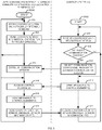
- Fig. 3 is a flow diagram of a process for providing enhanced routing in a contact center 120.
- the user communication device 101, the sensor manager 102, the contact center application 103, the browser 104, the internal sensor(s) 105, the external sensors 106A-106N, the networks 110A-110N, the contact center 120, the communication manger 121, the contact center queue(s) 122, the IVR system(s) 123, the contact center pool(s) 124, the chat bot 125, the web server 126, the contact center sensor manager 127, and the agent communication devices 130A-130N are stored-program-controlled entities, such as a computer or microprocessor, which performs the method of Figs.
- a computer readable storage medium such as a memory (i.e., a computer memory, a hard disk, and/or the like).
- a memory i.e., a computer memory, a hard disk, and/or the like.
- the process for the user communication device 101 starts in step 300A.
- the process for the contact center 120 starts in step 300B.
- the sensor manager 102 monitors bound external sensor(s) 106A-106N and optionally internal sensor(s) 105 in step 302.
- a sensor may be bound in various ways, such as, statically or dynamically. For example a sensor 105/106 may be statically bound based on a user selection, predefined rules, administration, and/or the like.
- a sensor 105/106 may dynamically bound based on various factors, such as, a context.
- a context may include a location 108 of the user communication device 101 (e.g., a specific room in a house), people in the location 108, a type of problem of a user of the user communication device 101 (e.g., an erratic heartbeat), a context of the user of the user communication device 101 (e.g., who is using the user communication device 101), sensors 106 in the location 108 of the user communication device 101 (e.g., those who can be managed), and/or the like.
- a combination of static and dynamic binding of sensors 105 may be used.
- the context may be based on various other factor(s) than location.
- the context may be where the customer is reporting a specific event (e.g., the customer is expressing the symptoms of Carbon Monoxide poisoning).
- the machine learning model 128 may dynamically bind one or more Carbon Monoxide sensors 106 and/or a furnace sensor 106 in the house to see if there is really a Carbon Monoxide problem in the customer's house.
- the contact center application 103 determines if there is a request to establish a communication session to the contact center 120 in step 304. If there is not a request for a communication session in step 304, the process goes back to step 302.
- a request to for the communication session with the contact center 120 is sent in step 306.
- a SIP INVITE message is sent in step 306 to establish a communication session with the contact center 120.
- information for the bound sensors 105/106 is sent in step 306. The information may be sent in the request to establish the communication session with the contact center 120 or in a separate message. For example, the information for the bound sensors 105/106 may be in a specific SIP header.
- the contact center 120 receives the request to establish the communication session/sensor information for the bound sensors 105/106 and establishes the communication session in step 308.
- the contact center sensor manager 127 gets the bound sensor information in step 310.
- the bound sensor information may be based on the machine learned model 128. For example, the bound sensor information may be based on a history of prior communication sessions with the contact center 120.
- the bound sensors 105/106 may be identified based on how prior customers and/or the same customer interacted with various contact center agents. For example, if the customer has had specific medical problems in the past that require the use of specific sensors 105/106 (e.g., specific types of readings), the bound sensors 105/106 may be different from another customer.
- the communication manager 121 routes the communication session in the contact center 120 in step 312. For example, based on the sensor information, the communication manager 121 may route the communication session to one of the contact center queue(s), the IVR system 123(s), the contact center pool(s) 124, the chat bot 125, the web server 126, and/or the like. In addition, one or more menus on the IVR system 123 or messages provided by the chat bot 125 may dynamically change based on the sensor information.
- the routing of step 312 may be also based on the machine learned model 128. For example, based on previous interactions of multiple different customers with a specific contact center agent, the machine learned model 128 may identify that particular contact center agent as an expert in handling a specific type of medical condition versus another contact center agent who has to continually escalate the communication to an expert. The routing may be based on the customer saying in a communication session that a specific contact center agent was particularly helpful. In this example, the communication session may be automatically routed based on the machine learning model 128 to the specific contact center agent communication device 130 based on the contact center agent's expertise and/or helpfulness.
- the prior history may be used by the machine learning model 128 to identify a specific contact center queue 122, IVR system 123, contact center pool 124, chat bot 125, web server 126, and/or the like for routing the communication session. For example, based on a specific sensor of an alarm system triggering, the machine learning model 128 may route the communication session to a specific contact center queue 122 where in the past the communication session was routed to a different contact center queue 122.
- an IVR menu may be dynamically changed based on the machine learning model 128.
- the machine learning model 128 may learn after a customer has called in more than twice that a specific menu is to be played to the customer because it is more likely that the customer will select the specific menu. In this case, the customer does not have to navigate through a series of menus to get to the menu he/she wants.
- the contact center sensor manager 127 via the communication manager 121, may optionally send a message(s) to the sensor manager 102 to control a control element(s) 107 in step 314.
- the sensor manager 102 receives the control message(s) in step 316.
- the sensor manager 102 then sends the message(s) to the control element(s) 107 in step 318.
- the sensor manager 102 via the contact center application 103, sends the updated location, event(s) (e.g., a change from a normal heart rate to a dangerous heart rate), sensor binding(s), and/or sensor information to the contact center 120 in step 320.
- the contact center sensor manager 127 receives the updated location, event(s), sensor binding(s), and/or sensor information in step 322.
- the sensor manager 102 sends the location/event(s)/binding(s)/sensor information in step 320 to the contact center sensor manager 127.
- the user communication device 101 process then goes back to step 302 when the communication session ends or back to step 316 while the communication session is established (indicated by the dashed line).
- the process may go back to step 312 and reroute the communication session based on the received sensor information of step 322.
- the contact center process goes back to step 308 when the communication session ends or back to step 314 while the communication session is established (indicated by the dashed line).
- the location, event(s), sensor bindings, sensor information of step 320 may be sent based on the message of step 314 or may be sent asynchronously at any time during the communication session.
- the contact center sensor manger 127 determines that the user has a high heart rate/blood pressure and routs the communication to a high priority contact center queue 122 in step 312. The user may be actually moved to the top of the contact center queue 122 based on how severe the heart rate/blood pressure is.
- the contact center sensor manger 127 sends, during the communication session, a control message to take another blood pressure reading in step 314 (e.g., based on a request from the contact center agent). The message is received in step 316 by the user communication device 101 and then sent to the blood pressure monitor in step 318.
- the sensor manager 102 receives the updated heart rate and sends the updated heart rate in step 320 to the contact center sensor manager 127.
- the contact center sensor manager 127 receives the updated heart rate and displays this information to a contact center agent in step 322.
- Fig. 4 is a flow diagram for dynamically binding sensors 105/106 to a communication session.
- Fig. 4 is illustrative example of step 320 of Fig. 3 .
- the process of Fig. 4 could also be used for step 302 of Fig. 3 .
- steps 400, 402, and 404 may happen in parallel (e.g., based on separate threads) and/or in series.
- the sensor monitor 102 determines if there is a location change in step 400. For example, a location change may be based on GPS. If there is not a location change in step 400 the process goes to step 410.
- the sensor monitor 102 identifies new external sensors 106 (and also control elements 107) if necessary in step 406. For example, if a user has left the house (a first location 108A) and moves to a vehicle (a second location 108N), the sensors 105/106/control element(s) 107 that can be managed by the sensor monitor 102 are identified in step 406. Sensors 105/106/control elements 107 are added/removed as necessary to the bound sensors based on rules in step 408. For example, a camera in the house may be removed and a camera in vehicle may be added in step 408. The process then goes to step 410 where the sensor monitor 102 monitors the bound sensors 105/106.
- the sensor monitor 102 then sends the sensor information as necessary in step 412 (e.g., according to rules). If the communication session has ended in step 414, the process goes to step 302. Otherwise, if the communication session has not ended in step 414, the process goes back to step 316.
- the sensor monitor 102 determines, in step 402, if an event has occurred.
- An event can be or may include any event that can be defined by one or more rules.
- an event may be, a detected high heart rate, a high blood pressure, a movement, a lighting level, a spoken word, a volume level, an accident (e.g., by an accident sensor in a vehicle), associated with a user of the first user communication device 101, a group of users associated with the first user communication device 101, and/or the like.
- the process goes to step 410. Otherwise, if an event is detected in step 402, the process goes to step 406 where new sensors are identified if necessary. For example, if a high heart rate is detected in step 402, the sensor monitor 102 may identify a camera as a new external sensor 106 to see if the user is moving. The steps of 408-414 are then implemented.
- the sensor monitor 102 determines, in step 404, if a request to add and/or remove a sensor 105/106 from the bound sensors is received. For example, the message of step 314 may have a request to add and/or remove a sensor 105/106 from the bound sensors. If a request to add and/or remove a bound sensor in step 404 is not received, the process goes to step 410. Otherwise, if a request to add and/or remove a bound sensor is received in step 404, the process goes to step 406-414 as described previously.
- Fig. 5 is a flow diagram of a process for providing enhanced routing in a contact center 120.
- the process for the user communication device 101 starts in step 500A.
- the process for the contact center 120 starts in step 500B.
- the sensor manager 102 monitors bound external sensor(s) 106A-106N and optionally internal sensor(s) 105 in step 502.
- a sensor 105/106 may be bound in various ways, such as, statically or dynamically.
- the sensor manager 102 sends, in step 504, location information, sensor information, and/or event(s) for the bound sensors.
- the process of steps 502-504 may repeat as indicated by the dashed line after step 504.
- the contact center sensor manager 127 receives the location information, sensor information, and/or event(s) in step 506.
- the contact center sensor manager 127 determines, in step 508, if there is a need to establish a communication session with the user communication device 101. For example, if a user's heart rate has increased over a threshold. If there is not a need to establish a communication session in step 508, the process goes back to step 506. Otherwise, if there is a need to establish a communication session in step 508, the communication manager 121 sends, in step 510, a request to establish a communication session in step 510.
- the contact center sensor manager 127 via the communication manager 121, may optionally send a message to the sensor manager 102 to control a control element(s) 107 in step 514.
- the sensor manager 102 receives the control message(s) in step 516.
- the sensor manager 102 then sends the message(s) to the control element(s) 107 in step 518.
- the sensor manager 102 via the contact center application 103, sends the updated location information, event(s), sensor binding(s), and/or sensor information to the contact center 120 in step 520. For example, based on the message of step 514, the sensor manager 102 sends the location/event(s)/binding(s)/sensor information in step 520 to the contact center sensor manager 127. The process then goes back to step 502 if the communication session has ended or back to step 516 (indicated by the dashed line) if the communication session has not ended. Likewise, the process in the contact center 120 goes back to step 506 if the communication has ended or back to step 514 if the communication session has not ended.
- the location, sensor bindings, sensor information of step 520 may be sent based on the message of step 514 or may be sent asynchronously.
- steps 514/522 may be running as a separate thread that runs during the communication session.
- step 516-520 may be running as a separate thread in the contact center 120.
- the process of Fig. 4 may also be used in steps 504/520 of Fig. 5 .
- Fig. 6 is a flow diagram of a process for applying a machine learning model to enhance routing and sensor binding in a contact center 120.
- the process starts in step 600.
- the communication manager 121 determines, in step 602, if a communication session has been established between the user and a contact center agent. If the communication session has not been established in step 602, the process of step 602 repeats. Otherwise, if the communication session has been established in step 602, machine learning model 128 monitors the communication session in step 604. For example, the machine learning model 128 monitors the communication session for keywords, phrases, inflection, pitch, sound levels (e.g., yelling), levels of stress (e.g., in the voice), gestures, and/or the like.
- the machine learning model 128 also identifies any sensors 105/106 that are used in the communication session.
- the machine learning model 128 applies the model, in step 606, to identify contact center agents/sensor bindings to optimize the routing in the contact center 120.
- the machine learning model 128 can identify particular contact center agents (e.g., groups of contact center agents that are assigned to a contact center queue 122) that handle specific types of situations better than other types. For example, the machine learning model 128 may learn that the contact center agent A can handle more stressful situations (e.g., where a patient is having a severe media condition) better than contact center agent B (e.g., where the contact center agent B handles routine calls better). In this example, the contact center agent A may be automatically assigned to a different contact center queue 122 than the contact center agent B.
- the machine learning model 128 can learn that in certain situations, that additional sensors 105/106 may automatically bound and/or unbound based on what is being said in the communication session. For instance, the machine learning model 128 may learn that based on previous conversations on a specific subject that heart monitor sensor 106 may be needed to take a reading. The machine learning model 128 can then tell the contact center sensor manager 127 to send a message to the user communication device 101A (i.e., sensor manager 102) to take a reading from the heart monitor sensor 106.
- the user communication device 101A i.e., sensor manager 102
- the contact center sensor manager 127 then updates the routing rules and/or sensor binding according to the machine learning model in step 608.
- the updated routing rules/sensor bindings are then used in step 312 of Fig. 3 .
- the process then goes back to step 602 to monitor the next communication session.
- Examples of the processors as described herein may include, but are not limited to, at least one of Qualcomm® Qualcomm® Qualcomm® 800 and 801, Qualcomm® Qualcomm® Qualcomm® 610 and 615 with 4G LTE Integration and 64-bit computing, Apple® A7 processor with 64-bit architecture, Apple® M7 motion coprocessors, Samsung® Exynos® series, the Intel® CoreTM family of processors, the Intel® Xeon® family of processors, the Intel® AtomTM family of processors, the Intel Itanium® family of processors, Intel® Core® i5-4670K and i7-4770K 22nm Haswell, Intel® Core® i5-3570K 22nm Ivy Bridge, the AMD® FXTM family of processors, AMD® FX-4300, FX-6300, and FX-8350 32nm Vishera, AMD® Kaveri processors, Texas Instruments® Jacinto C6000TM automotive infotainment processors, Texas Instruments® OMAPTM automotive-grade mobile processors, ARM® CortexTM-
- a distributed network 110 such as a LAN and/or the Internet
- the components of the system can be combined in to one or more devices or collocated on a particular node of a distributed network, such as an analog and/or digital telecommunications network, a packet-switch network, or a circuit-switched network.
- a distributed network such as an analog and/or digital telecommunications network, a packet-switch network, or a circuit-switched network.
- the various components can be located in a switch such as a PBX and media server, gateway, in one or more communications devices, at one or more users' premises, or some combination thereof.
- a switch such as a PBX and media server, gateway, in one or more communications devices, at one or more users' premises, or some combination thereof.
- one or more functional portions of the system could be distributed between a telecommunications device(s) and an associated computing device.
- the various links connecting the elements can be wired or wireless links, or any combination thereof, or any other known or later developed element(s) that is capable of supplying and/or communicating data to and from the connected elements.
- These wired or wireless links can also be secure links and may be capable of communicating encrypted information.
- Transmission media used as links can be any suitable carrier for electrical signals, including coaxial cables, copper wire and fiber optics, and may take the form of acoustic or light waves, such as those generated during radio-wave and infra-red data communications.
- the systems and methods of this disclosure can be implemented in conjunction with a special purpose computer, a programmed microprocessor or microcontroller and peripheral integrated circuit element(s), an ASIC or other integrated circuit, a digital signal processor, a hard-wired electronic or logic circuit such as discrete element circuit, a programmable logic device or gate array such as PLD, PLA, FPGA, PAL, special purpose computer, any comparable means, or the like.
- a special purpose computer e.g., cellular, Internet enabled, digital, analog, hybrids, and others
- telephones e.g., cellular, Internet enabled, digital, analog, hybrids, and others
- processors e.g., a single or multiple microprocessors
- memory e.g., a single or multiple microprocessors
- nonvolatile storage e.g., a single or multiple microprocessors
- input devices e.g., keyboards, pointing devices, and output devices.
- output devices e.g., a display, keyboards, and the like.
- alternative software implementations including, but not limited to, distributed processing or component/object distributed processing, parallel processing, or virtual machine processing can also be constructed to implement the methods described herein.
- the disclosed methods may be readily implemented in conjunction with software using object or object-oriented software development environments that provide portable source code that can be used on a variety of computer or workstation platforms.
- the disclosed system may be implemented partially or fully in hardware using standard logic circuits or VLSI design. Whether software or hardware is used to implement the systems in accordance with this disclosure is dependent on the speed and/or efficiency requirements of the system, the particular function, and the particular software or hardware systems or microprocessor or microcomputer systems being utilized.
- the disclosed methods may be partially implemented in software that can be stored on a storage medium, executed on programmed general-purpose computer with the cooperation of a controller and memory, a special purpose computer, a microprocessor, or the like.
- the systems and methods of this disclosure can be implemented as program embedded on personal computer such as an applet, JAVA® or CGI script, as a resource residing on a server or computer workstation, as a routine embedded in a dedicated measurement system, system component, or the like.
- the system can also be implemented by physically incorporating the system and/or method into a software and/or hardware system.
- the present disclosure in various embodiments, configurations, and aspects, includes components, methods, processes, systems and/or apparatus substantially as depicted and described herein, including various embodiments, subcombinations, and subsets thereof. Those of skill in the art will understand how to make and use the systems and methods disclosed herein after understanding the present disclosure.
- the present disclosure in various embodiments, configurations, and aspects, includes providing devices and processes in the absence of items not depicted and/or described herein or in various embodiments, configurations, or aspects hereof, including in the absence of such items as may have been used in previous devices or processes, e.g., for improving performance, achieving ease and ⁇ or reducing cost of implementation.
Landscapes
- Engineering & Computer Science (AREA)
- Signal Processing (AREA)
- Computer Networks & Wireless Communication (AREA)
- Marketing (AREA)
- Business, Economics & Management (AREA)
- Computing Systems (AREA)
- Medical Informatics (AREA)
- General Health & Medical Sciences (AREA)
- Health & Medical Sciences (AREA)
- Theoretical Computer Science (AREA)
- Software Systems (AREA)
- Artificial Intelligence (AREA)
- Physics & Mathematics (AREA)
- General Engineering & Computer Science (AREA)
- General Physics & Mathematics (AREA)
- Mathematical Physics (AREA)
- Evolutionary Computation (AREA)
- Data Mining & Analysis (AREA)
- Computer Vision & Pattern Recognition (AREA)
- Telephonic Communication Services (AREA)
- Mobile Radio Communication Systems (AREA)
Abstract
Description
- The disclosure relates generally to contact centers and particularly to systems and methods for routing communication sessions in a contact center.
- An Internet of Things (IoT) is a network of physical devices with sensors, such as, vehicles, home appliances, medical devices, and other network elements embedded with electronics, software, sensors, actuators, etc. These devices enable IoT devices to connect and exchange data, which creates opportunities for more direct integration of the physical world into computer-based systems. This can result in efficiency improvements, economic benefits, and reduced human exertions (See https://en.wikipedia.org/wiki/Internet of things)
- Typically, contact centers monitor and respond to events. Attributes are used to provide optimal matching of customers, agents, and other resources in the contact center where the events are handled by humans and bots. One area that is evolving is the automation of event reporting and management that does not require a human user to contact the contact center directly. However, currently, the contact centers of today fail to leverage the full capabilities of using IoT devices to provide an enhanced contact center experience.
- These and other needs are addressed by the various embodiments and configurations of the present disclosure. A first request to establish a communication session with a contact center is received from a user communication device. For example, a request to establish a voice communication session is received at the contact center. A machine learning model uses prior communication sessions with the contact center to identify a first set of one or more sensors that are external to the user communication device. External sensor information is received (e.g., during the request to establish the communication session) by the contact center. The external sensor information is from the first set of one or more sensors that are external to the user communication device. The communication session in the contact center is routed based on the received external sensor information. For example, instead of the communication session being routed to an Interactive Voice Response (IVR) system, the communication session is routed to a high priority contact center queue.
- The phrases "at least one", "one or more", "or", and "and/or" are open-ended expressions that are both conjunctive and disjunctive in operation. For example, each of the expressions "at least one of A, B and C", "at least one of A, B, or C", "one or more of A, B, and C", "one or more of A, B, or C", "A, B, and/or C", and "A, B, or C" means A alone, B alone, C alone, A and B together, A and C together, B and C together, or A, B and C together.
- The term "a" or "an" entity refers to one or more of that entity. As such, the terms "a" (or "an"), "one or more" and "at least one" can be used interchangeably herein. It is also to be noted that the terms "comprising", "including", and "having" can be used interchangeably.
- The term "automatic" and variations thereof, as used herein, refers to any process or operation, which is typically continuous or semi-continuous, done without material human input when the process or operation is performed. However, a process or operation can be automatic, even though performance of the process or operation uses material or immaterial human input, if the input is received before performance of the process or operation. Human input is deemed to be material if such input influences how the process or operation will be performed. Human input that consents to the performance of the process or operation is not deemed to be "material".
- Aspects of the present disclosure may take the form of an entirely hardware embodiment, an entirely software embodiment (including firmware, resident software, micro-code, etc.) or an embodiment combining software and hardware aspects that may all generally be referred to herein as a "circuit," "module" or "system." Any combination of one or more computer readable medium(s) may be utilized. The computer readable medium may be a computer readable signal medium or a computer readable storage medium.
- A computer readable storage medium may be, for example, but not limited to, an electronic, magnetic, optical, electromagnetic, infrared, or semiconductor system, apparatus, or device, or any suitable combination of the foregoing. More specific examples (a non-exhaustive list) of the computer readable storage medium would include the following: an electrical connection having one or more wires, a portable computer diskette, a hard disk, a random access memory (RAM), a read-only memory (ROM), an erasable programmable read-only memory (EPROM or Flash memory), an optical fiber, a portable compact disc read-only memory (CD-ROM), an optical storage device, a magnetic storage device, or any suitable combination of the foregoing. In the context of this document, a computer readable storage medium may be any tangible medium that can contain, or store a program for use by or in connection with an instruction execution system, apparatus, or device.
- A computer readable signal medium may include a propagated data signal with computer readable program code embodied therein, for example, in baseband or as part of a carrier wave. Such a propagated signal may take any of a variety of forms, including, but not limited to, electro-magnetic, optical, or any suitable combination thereof. A computer readable signal medium may be any computer readable medium that is not a computer readable storage medium and that can communicate, propagate, or transport a program for use by or in connection with an instruction execution system, apparatus, or device. Program code embodied on a computer readable medium may be transmitted using any appropriate medium, including but not limited to wireless, wireline, optical fiber cable, RF, etc., or any suitable combination of the foregoing.
- The terms "determine", "calculate" and "compute," and variations thereof, as used herein, are used interchangeably and include any type of methodology, process, mathematical operation or technique.
- The term "Session Initiation Protocol" (SIP) as used herein refers to an IETF-defined signaling protocol, widely used for controlling multimedia communication sessions such as voice and video calls over Internet Protocol (IP). The protocol can be used for creating, modifying and terminating two-party (unicast) or multiparty (multicast) sessions consisting of one or several media streams. The modification can involve changing addresses or ports, inviting more participants, and adding or deleting media streams. Other feasible application examples include video conferencing, streaming multimedia distribution, instant messaging, presence information, file transfer and online games. SIP is as described in RFC 3261, available from the Internet Engineering Task Force (IETF) Network Working Group, November 2000; this document and all other SIP RFCs describing SIP are hereby incorporated by reference in their entirety for all that they teach.
- The term "means" as used herein shall be given its broadest possible interpretation in accordance with 35 U.S.C., Section 112(f) and/or Section 112, Paragraph 6. Accordingly, a claim incorporating the term "means" shall cover all structures, materials, or acts set forth herein, and all of the equivalents thereof. Further, the structures, materials or acts and the equivalents thereof shall include all those described in the summary, brief description of the drawings, detailed description, abstract, and claims themselves.
- The preceding is a simplified summary to provide an understanding of some aspects of the disclosure. This summary is neither an extensive nor exhaustive overview of the disclosure and its various embodiments. It is intended neither to identify key or critical elements of the disclosure nor to delineate the scope of the disclosure but to present selected concepts of the disclosure in a simplified form as an introduction to the more detailed description presented below. As will be appreciated, other embodiments of the disclosure are possible utilizing, alone or in combination, one or more of the features set forth above or described in detail below. Also, while the disclosure is presented in terms of exemplary embodiments, it should be appreciated that individual aspects of the disclosure can be separately claimed.
-
-
Fig. 1 is a block diagram of a first illustrative system for providing enhanced routing in a contact center. -
Fig. 2 is a block diagram of a second illustrative system for providing enhanced routing in a contact center based on multiple locations of a user communication device. -
Fig. 3 is a flow diagram of a process for providing enhanced routing in a contact center. -
Fig. 4 is a flow diagram for dynamically binding sensors to a communication session. -
Fig. 5 is a flow diagram of a process for providing enhanced routing in a contact center. -
Fig. 6 is a flow diagram of a process for applying a machine learning model to enhance routing and sensor binding in a contact center. -
Fig. 1 is a block diagram of a firstillustrative system 100 for providing enhanced routing in acontact center 120. The firstillustrative system 100 comprises auser communication device 101,external sensors 106A-106N, control element(s) 107, alocation 108,networks 110A-110B, acontact center 120, andagent communication devices 130A-130N. - The
user communication device 101 can be or may include any user device that can communicate on the network 110, such as a Personal Computer (PC), a telephone, a video system, a conferencing system, a cellular telephone, a Personal Digital Assistant (PDA), a tablet device, a notebook device, a smartphone, and/or the like. Although not shown for convenience, additionaluser communication devices 101 may be connected to thenetwork 110B. - The
user communication device 101 is shown connected to thenetworks 110A-101B using wireless protocols. However, theuser communication device 101 may be connected to either of thenetworks 110A-110B using any known protocols, such as, wireless, wired, fiber optic, WiFi, Bluetooth, Ethernet, H.323, SIP, and/or the like. - The
user communication device 101 further comprises asensor manager 102, acontact center application 103, abrowser 104, and internal sensor(s) 105. Thesensor manager 102 can be or may include any hardware coupled with firmware/software that can manage and collect information from the internal sensor(s) 105/external sensor(s) 106A-106N. Thesensor manager 102 may retrieve information from the internal sensor(s) 105/external sensors 106A-106N. Thesensor manager 102 may send instructions to any one of the internal sensor(s) 105/external sensors 106A-106N to take a reading and/or take an action. Thesensor manager 102 may be part of thecontact center application 103. - The
contact center application 103 can be or may include any software/firmware that can communicate with thecontact center 120. Thecontact center application 103 can be used to establish a communication session with thecontact center 120. For example, thecontact center application 103 may be used to initiate a voice, video, Instant Messaging (IM), text messaging, email, virtual reality communication session, and/or the like with thecontact center 120. Thecontact center application 103 can be used to receive an incoming communication session (i.e. the same types of communication sessions discussed above) from thecontact center 120. - The
browser 104 can be or may include any knownbrowser 104, such as, Google Chrome™, Safari™, Internet Explorer™, Opera™, Firefox™, and/or the like. In one embodiment, thecontact center application 103 may be running in the browser 104 (e.g., where thecontact center application 103 is provided as a web page via the web server 126). - The internal sensor(s) 105 can be or may include any sensors that are internal to the
user communication device 101, such as, a touch screen, an accelerometer, a microphone, a camera, a button, a Global Positioning Satellite (GPS) system, and/or the like. - The
external sensors 106A-106N can be or may include any external sensor 106, such as, a camera, a pressure sensor, an Radio Frequency Identification (RFID) sensor, a heart monitor, a blood pressure monitor, a temperature sensor, a humidity sensor, a microphone, a biometric sensor (e.g., a retinal scanner), a blood oxygen sensor, a motion detector, a facial scanner, a door sensor, a window sensor, a LYDAR system and/or the like. - The control element(s) 107 can be or may include elements that can be controlled remotely, such as, a medical device, a camera (control rotation/zoom), a light, a printer, an appliance, an alarm, a radio, a vehicle, a LIDAR system, a display, an automated vehicle control system, a heating/air conditioning system, and/or the like. A
control element 107 may also have one or more sensors 106. For example, a heart monitor may have one or more sensors 106 that can be remotely controlled by the contactcenter sensor manager 127. - The
location 108 may be any location that is around theuser communication device 101, such as a room, a vehicle, a building, an area, and/or the like. Thelocation 108 may change as theuser communication device 101 moves. - The
networks 110A-110B can be or may include any collection of communication equipment that can send and receive electronic communications, such as the Internet, a Wide Area Network (WAN), a Local Area Network (LAN), a Voice over IP Network (VoIP), the Public Switched Telephone Network (PSTN), a packet switched network, a circuit switched network, a cellular network, a combination of these, and the like. The networks 1 10A-1 10B can use a variety of electronic protocols, such as Ethernet, Internet Protocol (IP), Session Initiation Protocol (SIP), Integrated Services Digital Network (ISDN), and the like. Thus, thenetworks 110A-110B are electronic communication networks configured to carry messages via packets and/or circuit switched communications. In one embodiment, thenetwork 110A is typically a private network, such as, a home network, a corporate network, a vehicle network, and/or the like and thenetwork 110B is typically a public network, such as the Internet or PSTN. In one embodiment thenetworks 110A-110B may be the same network. - The
contact center 120 can be or may include any hardware coupled with software that can manage communication sessions between theuser communication device 101 and thecontact center 120/agent communication devices 130A-130N. Thecontact center 120 further comprise acommunication manager 121, contact center queue(s) 122, IVR system(s) 123, contact center pool(s) 124, achat bot 125, aweb server 126, a contactcenter sensor manager 127, and amachine learning model 128. - The
communication manager 121 can be or may include any hardware coupled with firmware/software that can manage and route communication sessions in thecontact center 120, such as a Private Branch Exchange (PBX), and Automatic Call Distribution (ACD) system, a router, a network switch, an IM server, an email server, and/or the like. Thecommunication manager 121 can manage and route various types of communication sessions, such as, voice, video, multimedia, virtual reality, IM, email, text messaging, and/or the like. - The contact center queue(s) 122 can be or may include any computer construct that can be used to hold communication sessions. For example, the contact center queue(s) 122 can be used to hold voice communication sessions that are eventually routed to the
agent communication devices 130A-130N. The contact center queue(s) 122 can hold any kind of communication session. - The IVR system(s) 123 can be or may include any system that can interact with a user via voice. The IVR system(s) 123 may be used to gather information from users to make routing decisions in the
contact center 120. For example, the IVR system(s) 123 may be used to route an incoming voice/video communication session to acontact center queue 122 orcontact center pool 124. - The contact center pool(s) 124 can be or may include any computer construct that can hold a communication until selected by a contact center agent. The contact center pool(s) 124 can hold any kind of communication sessions.
- The
chat bot 125 can be or may include any hardware coupled with software that can interact with a user via text, such as, an Instant Messaging (IM) bot, a text messaging bot, a web server bot, and/or the like. - The
web server 126 can be or may include any knownweb server 126, such as Apache™, IIS™, nginx™, and/or the like. Theweb server 126 may provide thecontact center application 103 to theuser communication device 101 via thebrowser 104. - The contact
center sensor manager 127 can be or may include any firmware/software that can manage information received from thesensor application 102. The contactcenter sensor manager 127 can also control the control element(s) 107. - The
machine learning model 128 can be or may include any software that can automatically be used to identify which contact center agents, devices, and/orsensors 105/106 can handle specific types of communication sessions with specific customers to provide maximum efficiency and customer satisfaction in thecontact center 120. Themachine learning model 128 can constantly improve functions for routing the communication sessions in thecontact center 120. Themachine learning model 128 can be or may include any learning algorithm(s), such as, a linear regression algorithm, a logistic regression algorithm, a decision tree algorithm, a Naive Bayes algorithm, a K-means algorithm, and/or the like. - The
agent communication devices 130A-130N can be or may include any user communication device, such as theuser communication device 101. In one embodiment, an agent communication device (e.g., 130A) may comprise multiple agent communication devices 130, such as a telephone and a personal computer. -
Fig. 2 is a block diagram of a secondillustrative system 200 for providing enhanced routing in acontact center 120 based onmultiple locations 108A-108N of auser communication device 101. The secondillustrative system 200 comprises theuser communication device 101, theexternal sensors 106A-106N, control element(s) 107A-107N,locations 108A-108N,networks 110A-110N, thecontact center 120, and theagent communication devices 130A-130N. - The network 110N is typically similar to the
network 110A. However, the network 110N may be a public or private network based on implementation (e.g., based on thelocation 108N). -
Fig. 2 is used to show how theuser communication device 101 moves from thelocation 108A to thelocation 108N as shown bystep 210. As theuser communication device 101 moves from thelocation 108A (e.g., from a first room in a home) another location, theexternal sensors 106A-106C, the control element(s) 107A, and/or thenetwork 110A may change as shown instep 210. For example, the user communication device 101 (e.g., a smartphone) may move from thehome location 108A to alocation 108N on a street. In this example, thenetwork 110A may change from a WiFi network to a cellular network 110N. Theexternal sensors 106A-106C in the home may change to public sensors 106D-106N in the street. Likewise, the control element(s) 107A may change from home control elements 107 (e.g., medical devices/appliances) to controlsystems 107N in the street (e.g., a camera/light). -
Fig. 3 is a flow diagram of a process for providing enhanced routing in acontact center 120. Illustratively, theuser communication device 101, thesensor manager 102, thecontact center application 103, thebrowser 104, the internal sensor(s) 105, theexternal sensors 106A-106N, thenetworks 110A-110N, thecontact center 120, thecommunication manger 121, the contact center queue(s) 122, the IVR system(s) 123, the contact center pool(s) 124, thechat bot 125, theweb server 126, the contactcenter sensor manager 127, and theagent communication devices 130A-130N are stored-program-controlled entities, such as a computer or microprocessor, which performs the method ofFigs. 2-5 and the processes described herein by executing program instructions stored in a computer readable storage medium, such as a memory (i.e., a computer memory, a hard disk, and/or the like). Although the methods described inFigs. 2-5 are shown in a specific order, one of skill in the art would recognize that the steps inFigs. 2-5 may be implemented in different orders and/or be implemented in a multi-threaded environment. Moreover, various steps may be omitted or added based on implementation. - The process for the
user communication device 101 starts instep 300A. The process for thecontact center 120 starts instep 300B. Thesensor manager 102 monitors bound external sensor(s) 106A-106N and optionally internal sensor(s) 105 instep 302. A sensor (105/106) may be bound in various ways, such as, statically or dynamically. For example asensor 105/106 may be statically bound based on a user selection, predefined rules, administration, and/or the like. - A
sensor 105/106 may dynamically bound based on various factors, such as, a context. For example, a context may include alocation 108 of the user communication device 101 (e.g., a specific room in a house), people in thelocation 108, a type of problem of a user of the user communication device 101 (e.g., an erratic heartbeat), a context of the user of the user communication device 101 (e.g., who is using the user communication device 101), sensors 106 in thelocation 108 of the user communication device 101 (e.g., those who can be managed), and/or the like. In one embodiment, a combination of static and dynamic binding ofsensors 105 may be used. The context may be based on various other factor(s) than location. For example, the context may be where the customer is reporting a specific event (e.g., the customer is expressing the symptoms of Carbon Monoxide poisoning). In this example, themachine learning model 128 may dynamically bind one or more Carbon Monoxide sensors 106 and/or a furnace sensor 106 in the house to see if there is really a Carbon Monoxide problem in the customer's house. - The
contact center application 103 determines if there is a request to establish a communication session to thecontact center 120 instep 304. If there is not a request for a communication session instep 304, the process goes back tostep 302. - Otherwise, if there is a request to for a communication session with the
contact center 120, instep 304, a request to for the communication session with thecontact center 120 is sent instep 306. For example, a SIP INVITE message is sent instep 306 to establish a communication session with thecontact center 120. In addition, information for the boundsensors 105/106 is sent instep 306. The information may be sent in the request to establish the communication session with thecontact center 120 or in a separate message. For example, the information for the boundsensors 105/106 may be in a specific SIP header. - The contact center 120 (i.e., the communication manager 121) receives the request to establish the communication session/sensor information for the bound
sensors 105/106 and establishes the communication session instep 308. The contactcenter sensor manager 127 gets the bound sensor information instep 310. The bound sensor information may be based on the machine learnedmodel 128. For example, the bound sensor information may be based on a history of prior communication sessions with thecontact center 120. The boundsensors 105/106 may be identified based on how prior customers and/or the same customer interacted with various contact center agents. For example, if the customer has had specific medical problems in the past that require the use ofspecific sensors 105/106 (e.g., specific types of readings), the boundsensors 105/106 may be different from another customer. Based on the bound sensor information, thecommunication manager 121 routes the communication session in thecontact center 120 instep 312. For example, based on the sensor information, thecommunication manager 121 may route the communication session to one of the contact center queue(s), the IVR system 123(s), the contact center pool(s) 124, thechat bot 125, theweb server 126, and/or the like. In addition, one or more menus on theIVR system 123 or messages provided by thechat bot 125 may dynamically change based on the sensor information. - The routing of
step 312 may be also based on the machine learnedmodel 128. For example, based on previous interactions of multiple different customers with a specific contact center agent, the machine learnedmodel 128 may identify that particular contact center agent as an expert in handling a specific type of medical condition versus another contact center agent who has to continually escalate the communication to an expert. The routing may be based on the customer saying in a communication session that a specific contact center agent was particularly helpful. In this example, the communication session may be automatically routed based on themachine learning model 128 to the specific contact center agent communication device 130 based on the contact center agent's expertise and/or helpfulness. The prior history may be used by themachine learning model 128 to identify a specificcontact center queue 122,IVR system 123,contact center pool 124,chat bot 125,web server 126, and/or the like for routing the communication session. For example, based on a specific sensor of an alarm system triggering, themachine learning model 128 may route the communication session to a specificcontact center queue 122 where in the past the communication session was routed to a differentcontact center queue 122. - In one embodiment, an IVR menu may be dynamically changed based on the
machine learning model 128. For example, themachine learning model 128 may learn after a customer has called in more than twice that a specific menu is to be played to the customer because it is more likely that the customer will select the specific menu. In this case, the customer does not have to navigate through a series of menus to get to the menu he/she wants. - The contact
center sensor manager 127, via thecommunication manager 121, may optionally send a message(s) to thesensor manager 102 to control a control element(s) 107 instep 314. Thesensor manager 102 receives the control message(s) instep 316. Thesensor manager 102 then sends the message(s) to the control element(s) 107 instep 318. - The
sensor manager 102, via thecontact center application 103, sends the updated location, event(s) (e.g., a change from a normal heart rate to a dangerous heart rate), sensor binding(s), and/or sensor information to thecontact center 120 instep 320. The contactcenter sensor manager 127 receives the updated location, event(s), sensor binding(s), and/or sensor information instep 322. For example, based on the message ofstep 314, thesensor manager 102 sends the location/event(s)/binding(s)/sensor information instep 320 to the contactcenter sensor manager 127. Theuser communication device 101 process then goes back to step 302 when the communication session ends or back to step 316 while the communication session is established (indicated by the dashed line). In one embodiment, the process may go back to step 312 and reroute the communication session based on the received sensor information ofstep 322. The contact center process goes back to step 308 when the communication session ends or back to step 314 while the communication session is established (indicated by the dashed line). The location, event(s), sensor bindings, sensor information ofstep 320 may be sent based on the message ofstep 314 or may be sent asynchronously at any time during the communication session. - To illustrate the process of
Fig. 3 , consider the following example. A user, who is an elderly patient, has a group of sensors that are bound to his home telephone. The boundexternal sensors 106A-106N are a heart monitoring device, a video camera, and a blood pressure monitor. Thesensor manager 102 captures data from the boundexternal sensors 106A-106N instep 302. The user, who is not feeling well, makes a call to thecontact center 120 instep 304. The request is sent to thecontact center 120 instep 306 along with the user's heart rate, the user's blood pressure, and a picture of the user. Thecontact center 120 receives the request and establishes the communication session instep 308. The contactcenter sensor manager 127 gets the bound sensor information instep 310. The contactcenter sensor manger 127 determines that the user has a high heart rate/blood pressure and routs the communication to a high prioritycontact center queue 122 instep 312. The user may be actually moved to the top of thecontact center queue 122 based on how severe the heart rate/blood pressure is. The contactcenter sensor manger 127 sends, during the communication session, a control message to take another blood pressure reading in step 314 (e.g., based on a request from the contact center agent). The message is received instep 316 by theuser communication device 101 and then sent to the blood pressure monitor instep 318. Thesensor manager 102 receives the updated heart rate and sends the updated heart rate instep 320 to the contactcenter sensor manager 127. The contactcenter sensor manager 127 receives the updated heart rate and displays this information to a contact center agent instep 322. -
Fig. 4 is a flow diagram for dynamically bindingsensors 105/106 to a communication session.Fig. 4 is illustrative example ofstep 320 ofFig. 3 . The process ofFig. 4 could also be used forstep 302 ofFig. 3 . InFig. 4 ,steps sensor monitor 102 determines if there is a location change instep 400. For example, a location change may be based on GPS. If there is not a location change instep 400 the process goes to step 410. Otherwise, if there is a location change instep 400, thesensor monitor 102 identifies new external sensors 106 (and also control elements 107) if necessary instep 406. For example, if a user has left the house (afirst location 108A) and moves to a vehicle (asecond location 108N), thesensors 105/106/control element(s) 107 that can be managed by thesensor monitor 102 are identified instep 406.Sensors 105/106/control elements 107 are added/removed as necessary to the bound sensors based on rules instep 408. For example, a camera in the house may be removed and a camera in vehicle may be added instep 408. The process then goes to step 410 where thesensor monitor 102 monitors the boundsensors 105/106. The sensor monitor 102 then sends the sensor information as necessary in step 412 (e.g., according to rules). If the communication session has ended instep 414, the process goes to step 302. Otherwise, if the communication session has not ended instep 414, the process goes back tostep 316. - The
sensor monitor 102 determines, instep 402, if an event has occurred. An event can be or may include any event that can be defined by one or more rules. For example, an event may be, a detected high heart rate, a high blood pressure, a movement, a lighting level, a spoken word, a volume level, an accident (e.g., by an accident sensor in a vehicle), associated with a user of the firstuser communication device 101, a group of users associated with the firstuser communication device 101, and/or the like. If an event is not detected instep 402, the process goes to step 410. Otherwise, if an event is detected instep 402, the process goes to step 406 where new sensors are identified if necessary. For example, if a high heart rate is detected instep 402, thesensor monitor 102 may identify a camera as a new external sensor 106 to see if the user is moving. The steps of 408-414 are then implemented. - The
sensor monitor 102 determines, instep 404, if a request to add and/or remove asensor 105/106 from the bound sensors is received. For example, the message ofstep 314 may have a request to add and/or remove asensor 105/106 from the bound sensors. If a request to add and/or remove a bound sensor instep 404 is not received, the process goes to step 410. Otherwise, if a request to add and/or remove a bound sensor is received instep 404, the process goes to step 406-414 as described previously. -
Fig. 5 is a flow diagram of a process for providing enhanced routing in acontact center 120. The process for theuser communication device 101 starts instep 500A. The process for thecontact center 120 starts instep 500B. Thesensor manager 102 monitors bound external sensor(s) 106A-106N and optionally internal sensor(s) 105 instep 502. As discussed inFig. 3 , a sensor (105/106) may be bound in various ways, such as, statically or dynamically. Thesensor manager 102 sends, instep 504, location information, sensor information, and/or event(s) for the bound sensors. The process of steps 502-504 may repeat as indicated by the dashed line afterstep 504. - The contact
center sensor manager 127 receives the location information, sensor information, and/or event(s) instep 506. The contactcenter sensor manager 127 determines, instep 508, if there is a need to establish a communication session with theuser communication device 101. For example, if a user's heart rate has increased over a threshold. If there is not a need to establish a communication session instep 508, the process goes back tostep 506. Otherwise, if there is a need to establish a communication session instep 508, thecommunication manager 121 sends, instep 510, a request to establish a communication session instep 510. Instep 510, a communication device is selected (i.e., a communication agent device 130, acontact center queue 122, anIVR system 123, acontact center pool 124, achat bot 125, aweb server 126, etc.) that is used to establish the communication session with theuser communication device 101. The communication device is selected based on the received location/senor/event(s) ofstep 506. Theuser communication device 101 receives the request to establish the communication session and establishes the communication session with the contact center 120 (e.g., with a contact center agent) instep 512. - The contact
center sensor manager 127, via thecommunication manager 121, may optionally send a message to thesensor manager 102 to control a control element(s) 107 instep 514. Thesensor manager 102 receives the control message(s) instep 516. Thesensor manager 102 then sends the message(s) to the control element(s) 107 instep 518. - The
sensor manager 102, via thecontact center application 103, sends the updated location information, event(s), sensor binding(s), and/or sensor information to thecontact center 120 instep 520. For example, based on the message ofstep 514, thesensor manager 102 sends the location/event(s)/binding(s)/sensor information instep 520 to the contactcenter sensor manager 127. The process then goes back to step 502 if the communication session has ended or back to step 516 (indicated by the dashed line) if the communication session has not ended. Likewise, the process in thecontact center 120 goes back to step 506 if the communication has ended or back to step 514 if the communication session has not ended. The location, sensor bindings, sensor information ofstep 520 may be sent based on the message ofstep 514 or may be sent asynchronously. - For example, steps 514/522 may be running as a separate thread that runs during the communication session. Likewise, step 516-520 may be running as a separate thread in the
contact center 120. In addition, the process ofFig. 4 may also be used insteps 504/520 ofFig. 5 . -
Fig. 6 is a flow diagram of a process for applying a machine learning model to enhance routing and sensor binding in acontact center 120. The process starts instep 600. Thecommunication manager 121 determines, instep 602, if a communication session has been established between the user and a contact center agent. If the communication session has not been established instep 602, the process ofstep 602 repeats. Otherwise, if the communication session has been established instep 602,machine learning model 128 monitors the communication session instep 604. For example, themachine learning model 128 monitors the communication session for keywords, phrases, inflection, pitch, sound levels (e.g., yelling), levels of stress (e.g., in the voice), gestures, and/or the like. Themachine learning model 128 also identifies anysensors 105/106 that are used in the communication session. - The
machine learning model 128 applies the model, instep 606, to identify contact center agents/sensor bindings to optimize the routing in thecontact center 120. Themachine learning model 128 can identify particular contact center agents (e.g., groups of contact center agents that are assigned to a contact center queue 122) that handle specific types of situations better than other types. For example, themachine learning model 128 may learn that the contact center agent A can handle more stressful situations (e.g., where a patient is having a severe media condition) better than contact center agent B (e.g., where the contact center agent B handles routine calls better). In this example, the contact center agent A may be automatically assigned to a differentcontact center queue 122 than the contact center agent B. - The
machine learning model 128 can learn that in certain situations, thatadditional sensors 105/106 may automatically bound and/or unbound based on what is being said in the communication session. For instance, themachine learning model 128 may learn that based on previous conversations on a specific subject that heart monitor sensor 106 may be needed to take a reading. Themachine learning model 128 can then tell the contactcenter sensor manager 127 to send a message to the user communication device 101A (i.e., sensor manager 102) to take a reading from the heart monitor sensor 106. - The contact
center sensor manager 127 then updates the routing rules and/or sensor binding according to the machine learning model instep 608. The updated routing rules/sensor bindings are then used instep 312 ofFig. 3 . The process then goes back to step 602 to monitor the next communication session. - Examples of the processors as described herein may include, but are not limited to, at least one of Qualcomm® Snapdragon® 800 and 801, Qualcomm® Snapdragon® 610 and 615 with 4G LTE Integration and 64-bit computing, Apple® A7 processor with 64-bit architecture, Apple® M7 motion coprocessors, Samsung® Exynos® series, the Intel® Core™ family of processors, the Intel® Xeon® family of processors, the Intel® Atom™ family of processors, the Intel Itanium® family of processors, Intel® Core® i5-4670K and i7-4770K 22nm Haswell, Intel® Core® i5-3570K 22nm Ivy Bridge, the AMD® FX™ family of processors, AMD® FX-4300, FX-6300, and FX-8350 32nm Vishera, AMD® Kaveri processors, Texas Instruments® Jacinto C6000™ automotive infotainment processors, Texas Instruments® OMAP™ automotive-grade mobile processors, ARM® Cortex™-M processors, ARM® Cortex-A and ARM926EJ-S™ processors, other industry-equivalent processors, and may perform computational functions using any known or future-developed standard, instruction set, libraries, and/or architecture.
- Any of the steps, functions, and operations discussed herein can be performed continuously and automatically.
- However, to avoid unnecessarily obscuring the present disclosure, the preceding description omits a number of known structures and devices. This omission is not to be construed as a limitation of the scope of the claimed disclosure. Specific details are set forth to provide an understanding of the present disclosure. It should however be appreciated that the present disclosure may be practiced in a variety of ways beyond the specific detail set forth herein.
- Furthermore, while the exemplary embodiments illustrated herein show the various components of the system collocated, certain components of the system can be located remotely, at distant portions of a distributed network 110, such as a LAN and/or the Internet, or within a dedicated system. Thus, it should be appreciated, that the components of the system can be combined in to one or more devices or collocated on a particular node of a distributed network, such as an analog and/or digital telecommunications network, a packet-switch network, or a circuit-switched network. It will be appreciated from the preceding description, and for reasons of computational efficiency, that the components of the system can be arranged at any location within a distributed network of components without affecting the operation of the system. For example, the various components can be located in a switch such as a PBX and media server, gateway, in one or more communications devices, at one or more users' premises, or some combination thereof. Similarly, one or more functional portions of the system could be distributed between a telecommunications device(s) and an associated computing device.
- Furthermore, it should be appreciated that the various links connecting the elements can be wired or wireless links, or any combination thereof, or any other known or later developed element(s) that is capable of supplying and/or communicating data to and from the connected elements. These wired or wireless links can also be secure links and may be capable of communicating encrypted information. Transmission media used as links, for example, can be any suitable carrier for electrical signals, including coaxial cables, copper wire and fiber optics, and may take the form of acoustic or light waves, such as those generated during radio-wave and infra-red data communications.
- Also, while the flowcharts have been discussed and illustrated in relation to a particular sequence of events, it should be appreciated that changes, additions, and omissions to this sequence can occur without materially affecting the operation of the disclosure.
- A number of variations and modifications of the disclosure can be used. It would be possible to provide for some features of the disclosure without providing others.
- In yet another embodiment, the systems and methods of this disclosure can be implemented in conjunction with a special purpose computer, a programmed microprocessor or microcontroller and peripheral integrated circuit element(s), an ASIC or other integrated circuit, a digital signal processor, a hard-wired electronic or logic circuit such as discrete element circuit, a programmable logic device or gate array such as PLD, PLA, FPGA, PAL, special purpose computer, any comparable means, or the like. In general, any device(s) or means capable of implementing the methodology illustrated herein can be used to implement the various aspects of this disclosure. Exemplary hardware that can be used for the present disclosure includes computers, handheld devices, telephones (e.g., cellular, Internet enabled, digital, analog, hybrids, and others), and other hardware known in the art. Some of these devices include processors (e.g., a single or multiple microprocessors), memory, nonvolatile storage, input devices, and output devices. Furthermore, alternative software implementations including, but not limited to, distributed processing or component/object distributed processing, parallel processing, or virtual machine processing can also be constructed to implement the methods described herein.
- In yet another embodiment, the disclosed methods may be readily implemented in conjunction with software using object or object-oriented software development environments that provide portable source code that can be used on a variety of computer or workstation platforms. Alternatively, the disclosed system may be implemented partially or fully in hardware using standard logic circuits or VLSI design. Whether software or hardware is used to implement the systems in accordance with this disclosure is dependent on the speed and/or efficiency requirements of the system, the particular function, and the particular software or hardware systems or microprocessor or microcomputer systems being utilized.
- In yet another embodiment, the disclosed methods may be partially implemented in software that can be stored on a storage medium, executed on programmed general-purpose computer with the cooperation of a controller and memory, a special purpose computer, a microprocessor, or the like. In these instances, the systems and methods of this disclosure can be implemented as program embedded on personal computer such as an applet, JAVA® or CGI script, as a resource residing on a server or computer workstation, as a routine embedded in a dedicated measurement system, system component, or the like. The system can also be implemented by physically incorporating the system and/or method into a software and/or hardware system.
- Although the present disclosure describes components and functions implemented in the embodiments with reference to particular standards and protocols, the disclosure is not limited to such standards and protocols. Other similar standards and protocols not mentioned herein are in existence and are considered to be included in the present disclosure. Moreover, the standards and protocols mentioned herein and other similar standards and protocols not mentioned herein are periodically superseded by faster or more effective equivalents having essentially the same functions. Such replacement standards and protocols having the same functions are considered equivalents included in the present disclosure.
- The present disclosure, in various embodiments, configurations, and aspects, includes components, methods, processes, systems and/or apparatus substantially as depicted and described herein, including various embodiments, subcombinations, and subsets thereof. Those of skill in the art will understand how to make and use the systems and methods disclosed herein after understanding the present disclosure. The present disclosure, in various embodiments, configurations, and aspects, includes providing devices and processes in the absence of items not depicted and/or described herein or in various embodiments, configurations, or aspects hereof, including in the absence of such items as may have been used in previous devices or processes, e.g., for improving performance, achieving ease and\or reducing cost of implementation.
- The foregoing discussion of the disclosure has been presented for purposes of illustration and description. The foregoing is not intended to limit the disclosure to the form or forms disclosed herein. In the foregoing Detailed Description for example, various features of the disclosure are grouped together in one or more embodiments, configurations, or aspects for the purpose of streamlining the disclosure. The features of the embodiments, configurations, or aspects of the disclosure may be combined in alternate embodiments, configurations, or aspects other than those discussed above. This method of disclosure is not to be interpreted as reflecting an intention that the claimed disclosure requires more features than are expressly recited in each claim. Rather, as the following claims reflect, inventive aspects lie in less than all features of a single foregoing disclosed embodiment, configuration, or aspect. Thus, the following claims are hereby incorporated into this Detailed Description, with each claim standing on its own as a separate preferred embodiment of the disclosure.
- Moreover, though the description of the disclosure has included description of one or more embodiments, configurations, or aspects and certain variations and modifications, other variations, combinations, and modifications are within the scope of the disclosure, e.g., as may be within the skill and knowledge of those in the art, after understanding the present disclosure. It is intended to obtain rights which include alternative embodiments, configurations, or aspects to the extent permitted, including alternate, interchangeable and/or equivalent structures, functions, ranges or steps to those claimed, whether or not such alternate, interchangeable and/or equivalent structures, functions, ranges or steps are disclosed herein, and without intending to publicly dedicate any patentable subject matter.
Claims (15)
- A system comprising:a microprocessor; anda computer readable medium, coupled with the microprocessor and comprising microprocessor readable and executable instructions that, when executed by the microprocessor, cause the microprocessor to:receive, from a user communication device, a first request to establish a first communication session with a contact center;identify, based on a machine learned model of prior communication sessions with the contact center, a first set of one or more sensors that are external to the user communication device;receive first external sensor information, wherein the first external sensor information is from the first set of one or more sensors that are external to the user communication device; androute the first communication session in the contact center based on the received first external sensor information.
- The system of claim 1, wherein the first set of one or more sensors that are external to the user communication device are dynamically bound to the first communication session based on a first location of the user communication device when the first request to establish the first communication session is sent from the user communication device.
- The system of claim 2, wherein the first set of one or more sensors that are external to the user communication device are dynamically unbound from the first communication session and a second set of one or more sensors that are external to the user communication device are dynamically bound to the first communication session based on an event associated with the first communication session.
- The system of claim 2, wherein the first set of one or more sensors that are external to the user communication device are dynamically unbound from the first communication session and a second set of one or more sensors that are external to the user communication device are dynamically bound to the first communication session based on the user communication device moving from the first location to a second location during the first communication session.
- The system of claim 2, wherein microprocessor readable and executable instructions that, when executed by the microprocessor, further cause the microprocessor to:send a second request to the user communication device, where the second request is to dynamically add one or more additional sensors that are dynamically bound to the first communication session; andreceive second external sensor information from the one or more additional sensors that are dynamically bound to the first communication session.
- The system of claim 2, wherein one or more additional sensors are dynamically bound to the first communication session based on at least one of: an event associated with the one or more additional sensors, an event associated with a user of the first user communication device, and a group of users associated with the first user communication device.
- The system of claim 2, wherein the microprocessor readable and executable instructions that, when executed by the microprocessor, further cause the microprocessor to:
receive, from the user communication device, a second request to establish a second communication session with the contact center;
receive second external sensor information, wherein the second external sensor information is from a second set of one or more sensors that are external to the user communication device; and
route the second communication session in the contact center based on the second external sensor information, wherein the second communication session is routed differently in the contact center than the first communication session. - The system of claim 7, wherein the second set of one or more sensors that are external to the user communication device are dynamically bound to the second communication session based on a different location of the user communication device when the second request to establish the second communication session is sent from the user communication device.
- The system of claim 1, wherein routing the first communication session in the contact center based on the first external sensor information comprises routing the first communication session to an Interactive Voice Response (IVR) system or chat bot and wherein the first external sensor information is used to dynamically change one or more menus on the IVR system or messages provided by the chat bot.
- The system of claim 1, wherein, during the first communication session, the first external sensor information changes and wherein the microprocessor readable and executable instructions that, when executed by the microprocessor, further cause the microprocessor to:
reroute the first communication in the contact center based on the changed first external sensor information. - A method comprising:receiving, from a user communication device, a first request to establish a first communication session with a contact center;identifying, based on a machine learned model of prior communication sessions with the contact center, a first set of one or more sensors that are external to the user communication device;receiving first external sensor information, wherein the first external sensor information is from the first set of one or more sensors that are external to the user communication device; androuting the first communication session in the contact center based on the received first external sensor information.
- The method of claim 11, wherein the first set of one or more sensors that are external to the user communication device are dynamically bound to the first communication session based on a first location of the user communication device when the first request to establish the first communication session is sent from the user communication device.
- The method of claim 12, wherein the first set of one or more sensors that are external to the user communication device are dynamically unbound from the first communication session and a second set of one or more sensors that are external to the user communication device are dynamically bound to the first communication session based on an event associated with the first communication session.
- The method of claim 12, wherein the first set of one or more sensors that are external to the user communication device are dynamically unbound from the first communication session and a second set of one or more sensors that are external to the user communication device are dynamically bound to the first communication session based on the user communication device moving from the first location to a second location during the first communication session.
- The method of claim 12, further comprising:sending a second request to the user communication device, where the second request is to dynamically add one or more additional sensors that are dynamically bound to the first communication session; andreceiving second external sensor information from the one or more additional sensors that are dynamically bound to the first communication session.
Applications Claiming Priority (1)
| Application Number | Priority Date | Filing Date | Title |
|---|---|---|---|
| US16/201,579 US10631257B1 (en) | 2018-11-27 | 2018-11-27 | System and method for providing enhanced routing in a contact center |
Publications (2)
| Publication Number | Publication Date |
|---|---|
| EP3661180A1 true EP3661180A1 (en) | 2020-06-03 |
| EP3661180B1 EP3661180B1 (en) | 2021-07-07 |
Family
ID=68699299
Family Applications (1)
| Application Number | Title | Priority Date | Filing Date |
|---|---|---|---|
| EP19211763.8A Active EP3661180B1 (en) | 2018-11-27 | 2019-11-27 | System and method for providing enhanced routing in a contact center |
Country Status (3)
| Country | Link |
|---|---|
| US (1) | US10631257B1 (en) |
| EP (1) | EP3661180B1 (en) |
| CN (1) | CN111225028B (en) |
Families Citing this family (5)
| Publication number | Priority date | Publication date | Assignee | Title |
|---|---|---|---|---|
| US11489962B2 (en) | 2015-01-06 | 2022-11-01 | Cyara Solutions Pty Ltd | System and methods for automated customer response system mapping and duplication |
| US10291776B2 (en) * | 2015-01-06 | 2019-05-14 | Cyara Solutions Pty Ltd | Interactive voice response system crawler |
| CA3052174A1 (en) * | 2018-08-15 | 2020-02-15 | Royal Bank Of Canada | System and method for call centre management |
| US11705114B1 (en) | 2019-08-08 | 2023-07-18 | State Farm Mutual Automobile Insurance Company | Systems and methods for parsing multiple intents in natural language speech |
| US11882241B2 (en) | 2022-01-28 | 2024-01-23 | Zoom Video Communications, Inc. | Profile-based contact center request routing |
Citations (3)
| Publication number | Priority date | Publication date | Assignee | Title |
|---|---|---|---|---|
| US20120322430A1 (en) * | 2011-04-04 | 2012-12-20 | Bluelibris | Single button mobile telephone using server-based call routing |
| US20140314226A1 (en) * | 2013-04-18 | 2014-10-23 | Avaya Inc. | External contact center data collection and measurement |
| US20170180552A1 (en) * | 2015-12-18 | 2017-06-22 | At&T Mobility Ii Llc | Enhanced automated attendant system |
Family Cites Families (59)
| Publication number | Priority date | Publication date | Assignee | Title |
|---|---|---|---|---|
| IL134035A0 (en) * | 2000-01-13 | 2001-04-30 | Ronen Daniel | A device, system and method for remote push-publishing of content onto display screens of mobile devices including a screen saver application |
| US20020141404A1 (en) * | 2001-04-03 | 2002-10-03 | Michael Wengrovitz | Call routing using information in session initiation protocol messages |
| US6876727B2 (en) * | 2002-07-24 | 2005-04-05 | Sbc Properties, Lp | Voice over IP method for developing interactive voice response system |
| US20100215156A1 (en) * | 2006-04-06 | 2010-08-26 | Industrial Technology Research Institute | Structural data transmission method and system for interactive voice response system |
| US7809663B1 (en) * | 2006-05-22 | 2010-10-05 | Convergys Cmg Utah, Inc. | System and method for supporting the utilization of machine language |
| US8750489B2 (en) * | 2008-10-23 | 2014-06-10 | International Business Machines Corporation | System and method for automatic call segmentation at call center |
| US20130191185A1 (en) * | 2012-01-24 | 2013-07-25 | Brian R. Galvin | System and method for conducting real-time and historical analysis of complex customer care processes |
| US9674356B2 (en) * | 2012-11-21 | 2017-06-06 | Genesys Telecommunications Laboratories, Inc. | Dynamic recommendation of routing rules for contact center use |
| CN203178681U (en) * | 2013-04-10 | 2013-09-04 | 南通纺织职业技术学院 | Intelligent elderly caring watch |
| JP2017508188A (en) * | 2014-01-28 | 2017-03-23 | シンプル エモーション, インコーポレイテッドSimple Emotion, Inc. | A method for adaptive spoken dialogue |
| US10235639B1 (en) * | 2014-03-14 | 2019-03-19 | Directly Software, Inc. | Al based CRM system |
| US9015250B1 (en) * | 2014-04-02 | 2015-04-21 | Aria Solutions Inc. | Adaptive cloud-based work routing |
| US9860124B2 (en) * | 2014-04-02 | 2018-01-02 | Aria Solutions, Inc. | Configurable cloud-based routing |
| US10586175B2 (en) * | 2014-05-23 | 2020-03-10 | NewVoiceMedia Ltd. | System and method for an optimized, self-learning and self-organizing contact center |
| AU2015306693A1 (en) * | 2014-08-25 | 2017-03-02 | Shl Us Llc | Customizable machine learning models |
| US11200581B2 (en) * | 2018-05-10 | 2021-12-14 | Hubspot, Inc. | Multi-client service system platform |
| KR20160103186A (en) * | 2015-01-21 | 2016-09-01 | 삼성전자주식회사 | Medical device diagnosis apparatus and controlling method thereof |
| US9940187B2 (en) * | 2015-04-17 | 2018-04-10 | Microsoft Technology Licensing, Llc | Nexus determination in a computing device |
| CN104952447B (en) * | 2015-04-30 | 2020-03-27 | 深圳市全球锁安防系统工程有限公司 | Intelligent wearable device for elderly people's health service and voice recognition method |
| CN104796485B (en) * | 2015-04-30 | 2019-09-10 | 深圳市全球锁安防系统工程有限公司 | A kind of the elderly Yunan County health service platform and big data processing method |
| US10007513B2 (en) * | 2015-08-27 | 2018-06-26 | FogHorn Systems, Inc. | Edge intelligence platform, and internet of things sensor streams system |
| JP6925321B2 (en) * | 2015-08-27 | 2021-08-25 | フォグホーン システムズ, インコーポレイテッドFoghorn Systems, Inc. | Edge Intelligence Platform and Internet of Things Sensor Stream System |
| CN205230136U (en) * | 2015-11-06 | 2016-05-11 | 天津世未科技有限公司 | Community medicine management system based on thing networking |
| CN105468145B (en) * | 2015-11-18 | 2019-05-28 | 北京航空航天大学 | A kind of robot man-machine interaction method and device based on gesture and speech recognition |
| US10003508B1 (en) * | 2015-11-30 | 2018-06-19 | Amdocs Development Limited | Event-based system, method, and computer program for intervening in a network service |
| IL243358A0 (en) * | 2015-12-27 | 2016-04-21 | Alex Rivkin | Personal emergency saver system and method |
| CN105721700A (en) * | 2016-02-22 | 2016-06-29 | 上海理工大学 | Voice help-seeking system based on Android phone |
| CN105975780A (en) * | 2016-05-10 | 2016-09-28 | 华南理工大学 | Machine inquiry system based on virtual reality interaction technology |
| CA2984304C (en) * | 2016-11-01 | 2023-06-13 | Transaction Network Services, Inc. | Systems and methods for automatically conducting risk assessments for telephony communications |
| CA2965457C (en) * | 2016-11-03 | 2019-06-11 | Chickadvisor Inc. | Computer-implemented system and method for providing on-demand expert advice to a consumer |
| US20180131810A1 (en) * | 2016-11-04 | 2018-05-10 | T-Mobile, Usa, Inc. | Machine learning-based customer care routing |
| CN206366178U (en) * | 2016-12-23 | 2017-08-01 | 武汉市马里欧网络有限公司 | It is a kind of that there is monitoring and the AR gaming projection devices of calling function |
| US10380516B1 (en) * | 2017-01-16 | 2019-08-13 | Directly Software, Inc. | CRM including multi-thread messaging |
| US10440187B1 (en) * | 2017-01-16 | 2019-10-08 | Directly Software, Inc. | Bootstrapped predicative routing in CRM |
| US10176800B2 (en) * | 2017-02-10 | 2019-01-08 | International Business Machines Corporation | Procedure dialogs using reinforcement learning |
| MY195692A (en) * | 2017-02-17 | 2023-02-04 | Kasatria Analytics Sdn Bhd | Computer Implemented System and Method for Customer Profiling Using Micro-Conversions Via Machine Learning |
| US10332505B2 (en) * | 2017-03-09 | 2019-06-25 | Capital One Services, Llc | Systems and methods for providing automated natural language dialogue with customers |
| US10277743B1 (en) * | 2017-03-21 | 2019-04-30 | Amazon Technologies, Inc. | Configurable natural language contact flow |
| US11151472B2 (en) * | 2017-03-31 | 2021-10-19 | At&T Intellectual Property I, L.P. | Dynamic updating of machine learning models |
| US10242554B2 (en) * | 2017-04-18 | 2019-03-26 | Carbyne Ltd. | System and method thereof for automatically routing a communication request addressed to a public safety answering point (PSAP) to a suitable dispatch unit |
| US20180308100A1 (en) * | 2017-04-19 | 2018-10-25 | Risto Haukioja | System and method of client recognition for service provider transactions |
| JP6880974B2 (en) * | 2017-04-19 | 2021-06-02 | 富士通株式会社 | Information output program, information output method and information processing device |
| US10977565B2 (en) * | 2017-04-28 | 2021-04-13 | At&T Intellectual Property I, L.P. | Bridging heterogeneous domains with parallel transport and sparse coding for machine learning models |
| WO2018204253A1 (en) * | 2017-05-01 | 2018-11-08 | PiMios, LLC | Automotive diagnostics using supervised learning models |
| US11037060B2 (en) * | 2017-05-05 | 2021-06-15 | Arimo, LLC | Analyzing sequence data using neural networks |
| AU2018273197B2 (en) * | 2017-05-22 | 2021-08-12 | Genesys Cloud Services, Inc. | System and method for dynamic dialog control for contact center systems |
| US10306068B1 (en) * | 2017-07-06 | 2019-05-28 | United Services Automobile Association (Usaa) | Call center load balancing and routing management |
| CA3014377A1 (en) * | 2017-08-16 | 2019-02-16 | Royal Bank Of Canada | Systems and methods for early fraud detection |
| US10257355B1 (en) * | 2017-08-29 | 2019-04-09 | Massachusetts Mutual Life Insurance Company | System and method for managing customer call-backs |
| US10431203B2 (en) * | 2017-09-05 | 2019-10-01 | International Business Machines Corporation | Machine training for native language and fluency identification |
| US11568231B2 (en) * | 2017-12-08 | 2023-01-31 | Raytheon Bbn Technologies Corp. | Waypoint detection for a contact center analysis system |
| US20190188583A1 (en) * | 2017-12-20 | 2019-06-20 | International Business Machines Corporation | System and method to recommend mitigation action using conversational agent |
| US20190222540A1 (en) * | 2018-01-16 | 2019-07-18 | Capital One Services, Llc | Automated chat assistant systems for providing interactive data using natural language processing |
| US10044647B1 (en) * | 2018-03-09 | 2018-08-07 | Capital One Services, Llc | Systems and methods for controlling enrollment and secure persistent SMS texting account servicing with an intelligent assistant |
| US20190279256A1 (en) * | 2018-03-09 | 2019-09-12 | Avaya Inc. | System and method for making real-time decisions for routing communications and information in a contact center |
| US11790394B2 (en) * | 2018-03-16 | 2023-10-17 | Advocado, Inc. | Methods and systems for automatic call routing with no caller intervention using anonymous online user behavior |
| US11810126B2 (en) * | 2018-04-04 | 2023-11-07 | Jpmorgan Chase Bank, N.A. | System and method for implementing an intelligent customer service query management and routing system |
| US10484532B1 (en) * | 2018-10-23 | 2019-11-19 | Capital One Services, Llc | System and method detecting fraud using machine-learning and recorded voice clips |
| US10356244B1 (en) * | 2019-02-08 | 2019-07-16 | Fmr Llc | Automated predictive call routing using reinforcement learning |
-
2018
- 2018-11-27 US US16/201,579 patent/US10631257B1/en active Active
-
2019
- 2019-11-27 EP EP19211763.8A patent/EP3661180B1/en active Active
- 2019-11-27 CN CN201911177845.7A patent/CN111225028B/en active Active
Patent Citations (3)
| Publication number | Priority date | Publication date | Assignee | Title |
|---|---|---|---|---|
| US20120322430A1 (en) * | 2011-04-04 | 2012-12-20 | Bluelibris | Single button mobile telephone using server-based call routing |
| US20140314226A1 (en) * | 2013-04-18 | 2014-10-23 | Avaya Inc. | External contact center data collection and measurement |
| US20170180552A1 (en) * | 2015-12-18 | 2017-06-22 | At&T Mobility Ii Llc | Enhanced automated attendant system |
Non-Patent Citations (1)
| Title |
|---|
| "RFC 3261", November 2000, INTERNET ENGINEERING TASK FORCE (IETF) NETWORK WORKING GROUP |
Also Published As
| Publication number | Publication date |
|---|---|
| CN111225028B (en) | 2023-04-18 |
| CN111225028A (en) | 2020-06-02 |
| US10631257B1 (en) | 2020-04-21 |
| EP3661180B1 (en) | 2021-07-07 |
Similar Documents
| Publication | Publication Date | Title |
|---|---|---|
| EP3661180B1 (en) | System and method for providing enhanced routing in a contact center | |
| US10764435B2 (en) | Smart customer assistant in a contact center | |
| US11108911B2 (en) | System and method for flexible routing | |
| JP2021182387A (en) | Variable chat box | |
| US10862929B2 (en) | Systems and methods for providing automated progress updates in a contact center | |
| US11895061B2 (en) | Dynamic prioritization of collaboration between human and virtual agents | |
| US10938867B2 (en) | Automatic on hold communication session state management in a contact center | |
| US20200228655A1 (en) | Communication session hold time management in a contact center | |
| US9894201B1 (en) | Ongoing text analysis to self-regulate network node allocations and contact center adjustments | |
| US10827074B2 (en) | Enforcement of contact center communication session routing behaviors | |
| US11856141B2 (en) | Methods and systems of providing response based on communication session participant request urgency | |
| US11595326B2 (en) | Multi-dimensional/multi-actor conversational bot | |
| US20210227169A1 (en) | System and method for using predictive analysis to generate a hierarchical graphical layout | |
| US20200145534A1 (en) | Intelligent multi-channel interaction management within a contact center communication system | |
| US20200128050A1 (en) | Context based communication session bridging | |
| US10848908B2 (en) | Proximity based communication information sharing | |
| US10924894B2 (en) | System and method for sending and receiving non-visual messages in an electronic audio communication session | |
| US20210201247A1 (en) | System and method to assign action items using artificial intelligence | |
| US20250124456A1 (en) | Technologies for dynamic frequently asked question generation and contact center agent assist integration | |
| US10999430B2 (en) | Intelligent user device management in a multi device environment | |
| US20240202783A1 (en) | Systems and methods relating to implementation of predictive models in contact centers | |
| EP3467732A1 (en) | Split enterprise/provider workflows | |
| US11659089B1 (en) | Systems and methods relating to managing cross-channel interactions in contact centers | |
| US20200007685A1 (en) | Prioritization of routing for escalated communication sessions in a contact center | |
| US12052390B2 (en) | Selective aggregation of enqueued nodes into a subnetwork for simultaneous communication |
Legal Events
| Date | Code | Title | Description |
|---|---|---|---|
| PUAI | Public reference made under article 153(3) epc to a published international application that has entered the european phase |
Free format text: ORIGINAL CODE: 0009012 |
|
| STAA | Information on the status of an ep patent application or granted ep patent |
Free format text: STATUS: REQUEST FOR EXAMINATION WAS MADE |
|
| 17P | Request for examination filed |
Effective date: 20191127 |
|
| AK | Designated contracting states |
Kind code of ref document: A1 Designated state(s): AL AT BE BG CH CY CZ DE DK EE ES FI FR GB GR HR HU IE IS IT LI LT LU LV MC MK MT NL NO PL PT RO RS SE SI SK SM TR |
|
| AX | Request for extension of the european patent |
Extension state: BA ME |
|
| RIN1 | Information on inventor provided before grant (corrected) |
Inventor name: NEKRASHEVICH, ROMAN Inventor name: BAR-YOAV, RONEN Inventor name: BARZUZA, TAMAR Inventor name: SERERO, EYAL Inventor name: NETANEL, GAL |
|
| GRAP | Despatch of communication of intention to grant a patent |
Free format text: ORIGINAL CODE: EPIDOSNIGR1 |
|
| STAA | Information on the status of an ep patent application or granted ep patent |
Free format text: STATUS: GRANT OF PATENT IS INTENDED |
|
| INTG | Intention to grant announced |
Effective date: 20210205 |
|
| GRAS | Grant fee paid |
Free format text: ORIGINAL CODE: EPIDOSNIGR3 |
|
| GRAA | (expected) grant |
Free format text: ORIGINAL CODE: 0009210 |
|
| STAA | Information on the status of an ep patent application or granted ep patent |
Free format text: STATUS: THE PATENT HAS BEEN GRANTED |
|
| AK | Designated contracting states |
Kind code of ref document: B1 Designated state(s): AL AT BE BG CH CY CZ DE DK EE ES FI FR GB GR HR HU IE IS IT LI LT LU LV MC MK MT NL NO PL PT RO RS SE SI SK SM TR |
|
| REG | Reference to a national code |
Ref country code: GB Ref legal event code: FG4D |
|
| REG | Reference to a national code |
Ref country code: AT Ref legal event code: REF Ref document number: 1409724 Country of ref document: AT Kind code of ref document: T Effective date: 20210715 |
|
| REG | Reference to a national code |
Ref country code: DE Ref legal event code: R096 Ref document number: 602019005938 Country of ref document: DE |
|
| REG | Reference to a national code |
Ref country code: IE Ref legal event code: FG4D |
|
| REG | Reference to a national code |
Ref country code: LT Ref legal event code: MG9D |
|
| REG | Reference to a national code |
Ref country code: NL Ref legal event code: MP Effective date: 20210707 |
|
| REG | Reference to a national code |
Ref country code: AT Ref legal event code: MK05 Ref document number: 1409724 Country of ref document: AT Kind code of ref document: T Effective date: 20210707 |
|
| PG25 | Lapsed in a contracting state [announced via postgrant information from national office to epo] |
Ref country code: ES Free format text: LAPSE BECAUSE OF FAILURE TO SUBMIT A TRANSLATION OF THE DESCRIPTION OR TO PAY THE FEE WITHIN THE PRESCRIBED TIME-LIMIT Effective date: 20210707 Ref country code: RS Free format text: LAPSE BECAUSE OF FAILURE TO SUBMIT A TRANSLATION OF THE DESCRIPTION OR TO PAY THE FEE WITHIN THE PRESCRIBED TIME-LIMIT Effective date: 20210707 Ref country code: SE Free format text: LAPSE BECAUSE OF FAILURE TO SUBMIT A TRANSLATION OF THE DESCRIPTION OR TO PAY THE FEE WITHIN THE PRESCRIBED TIME-LIMIT Effective date: 20210707 Ref country code: LT Free format text: LAPSE BECAUSE OF FAILURE TO SUBMIT A TRANSLATION OF THE DESCRIPTION OR TO PAY THE FEE WITHIN THE PRESCRIBED TIME-LIMIT Effective date: 20210707 Ref country code: BG Free format text: LAPSE BECAUSE OF FAILURE TO SUBMIT A TRANSLATION OF THE DESCRIPTION OR TO PAY THE FEE WITHIN THE PRESCRIBED TIME-LIMIT Effective date: 20211007 Ref country code: AT Free format text: LAPSE BECAUSE OF FAILURE TO SUBMIT A TRANSLATION OF THE DESCRIPTION OR TO PAY THE FEE WITHIN THE PRESCRIBED TIME-LIMIT Effective date: 20210707 Ref country code: HR Free format text: LAPSE BECAUSE OF FAILURE TO SUBMIT A TRANSLATION OF THE DESCRIPTION OR TO PAY THE FEE WITHIN THE PRESCRIBED TIME-LIMIT Effective date: 20210707 Ref country code: FI Free format text: LAPSE BECAUSE OF FAILURE TO SUBMIT A TRANSLATION OF THE DESCRIPTION OR TO PAY THE FEE WITHIN THE PRESCRIBED TIME-LIMIT Effective date: 20210707 Ref country code: PT Free format text: LAPSE BECAUSE OF FAILURE TO SUBMIT A TRANSLATION OF THE DESCRIPTION OR TO PAY THE FEE WITHIN THE PRESCRIBED TIME-LIMIT Effective date: 20211108 Ref country code: NO Free format text: LAPSE BECAUSE OF FAILURE TO SUBMIT A TRANSLATION OF THE DESCRIPTION OR TO PAY THE FEE WITHIN THE PRESCRIBED TIME-LIMIT Effective date: 20211007 Ref country code: NL Free format text: LAPSE BECAUSE OF FAILURE TO SUBMIT A TRANSLATION OF THE DESCRIPTION OR TO PAY THE FEE WITHIN THE PRESCRIBED TIME-LIMIT Effective date: 20210707 |
|
| PG25 | Lapsed in a contracting state [announced via postgrant information from national office to epo] |
Ref country code: PL Free format text: LAPSE BECAUSE OF FAILURE TO SUBMIT A TRANSLATION OF THE DESCRIPTION OR TO PAY THE FEE WITHIN THE PRESCRIBED TIME-LIMIT Effective date: 20210707 Ref country code: LV Free format text: LAPSE BECAUSE OF FAILURE TO SUBMIT A TRANSLATION OF THE DESCRIPTION OR TO PAY THE FEE WITHIN THE PRESCRIBED TIME-LIMIT Effective date: 20210707 Ref country code: GR Free format text: LAPSE BECAUSE OF FAILURE TO SUBMIT A TRANSLATION OF THE DESCRIPTION OR TO PAY THE FEE WITHIN THE PRESCRIBED TIME-LIMIT Effective date: 20211008 |
|
| REG | Reference to a national code |
Ref country code: DE Ref legal event code: R097 Ref document number: 602019005938 Country of ref document: DE |
|
| PG25 | Lapsed in a contracting state [announced via postgrant information from national office to epo] |
Ref country code: DK Free format text: LAPSE BECAUSE OF FAILURE TO SUBMIT A TRANSLATION OF THE DESCRIPTION OR TO PAY THE FEE WITHIN THE PRESCRIBED TIME-LIMIT Effective date: 20210707 |
|
| PLBE | No opposition filed within time limit |
Free format text: ORIGINAL CODE: 0009261 |
|
| STAA | Information on the status of an ep patent application or granted ep patent |
Free format text: STATUS: NO OPPOSITION FILED WITHIN TIME LIMIT |
|
| PG25 | Lapsed in a contracting state [announced via postgrant information from national office to epo] |
Ref country code: SM Free format text: LAPSE BECAUSE OF FAILURE TO SUBMIT A TRANSLATION OF THE DESCRIPTION OR TO PAY THE FEE WITHIN THE PRESCRIBED TIME-LIMIT Effective date: 20210707 Ref country code: SK Free format text: LAPSE BECAUSE OF FAILURE TO SUBMIT A TRANSLATION OF THE DESCRIPTION OR TO PAY THE FEE WITHIN THE PRESCRIBED TIME-LIMIT Effective date: 20210707 Ref country code: RO Free format text: LAPSE BECAUSE OF FAILURE TO SUBMIT A TRANSLATION OF THE DESCRIPTION OR TO PAY THE FEE WITHIN THE PRESCRIBED TIME-LIMIT Effective date: 20210707 Ref country code: EE Free format text: LAPSE BECAUSE OF FAILURE TO SUBMIT A TRANSLATION OF THE DESCRIPTION OR TO PAY THE FEE WITHIN THE PRESCRIBED TIME-LIMIT Effective date: 20210707 Ref country code: CZ Free format text: LAPSE BECAUSE OF FAILURE TO SUBMIT A TRANSLATION OF THE DESCRIPTION OR TO PAY THE FEE WITHIN THE PRESCRIBED TIME-LIMIT Effective date: 20210707 Ref country code: AL Free format text: LAPSE BECAUSE OF FAILURE TO SUBMIT A TRANSLATION OF THE DESCRIPTION OR TO PAY THE FEE WITHIN THE PRESCRIBED TIME-LIMIT Effective date: 20210707 |
|
| 26N | No opposition filed |
Effective date: 20220408 |
|
| PG25 | Lapsed in a contracting state [announced via postgrant information from national office to epo] |
Ref country code: MC Free format text: LAPSE BECAUSE OF FAILURE TO SUBMIT A TRANSLATION OF THE DESCRIPTION OR TO PAY THE FEE WITHIN THE PRESCRIBED TIME-LIMIT Effective date: 20210707 |
|
| PG25 | Lapsed in a contracting state [announced via postgrant information from national office to epo] |
Ref country code: LU Free format text: LAPSE BECAUSE OF NON-PAYMENT OF DUE FEES Effective date: 20211127 Ref country code: IT Free format text: LAPSE BECAUSE OF FAILURE TO SUBMIT A TRANSLATION OF THE DESCRIPTION OR TO PAY THE FEE WITHIN THE PRESCRIBED TIME-LIMIT Effective date: 20210707 Ref country code: BE Free format text: LAPSE BECAUSE OF NON-PAYMENT OF DUE FEES Effective date: 20211130 |
|
| REG | Reference to a national code |
Ref country code: BE Ref legal event code: MM Effective date: 20211130 |
|
| PG25 | Lapsed in a contracting state [announced via postgrant information from national office to epo] |
Ref country code: IE Free format text: LAPSE BECAUSE OF NON-PAYMENT OF DUE FEES Effective date: 20211127 |
|
| PG25 | Lapsed in a contracting state [announced via postgrant information from national office to epo] |
Ref country code: CY Free format text: LAPSE BECAUSE OF FAILURE TO SUBMIT A TRANSLATION OF THE DESCRIPTION OR TO PAY THE FEE WITHIN THE PRESCRIBED TIME-LIMIT Effective date: 20210707 |
|
| REG | Reference to a national code |
Ref country code: CH Ref legal event code: PL |
|
| PG25 | Lapsed in a contracting state [announced via postgrant information from national office to epo] |
Ref country code: LI Free format text: LAPSE BECAUSE OF NON-PAYMENT OF DUE FEES Effective date: 20221130 Ref country code: HU Free format text: LAPSE BECAUSE OF FAILURE TO SUBMIT A TRANSLATION OF THE DESCRIPTION OR TO PAY THE FEE WITHIN THE PRESCRIBED TIME-LIMIT; INVALID AB INITIO Effective date: 20191127 Ref country code: CH Free format text: LAPSE BECAUSE OF NON-PAYMENT OF DUE FEES Effective date: 20221130 |
|
| PG25 | Lapsed in a contracting state [announced via postgrant information from national office to epo] |
Ref country code: MK Free format text: LAPSE BECAUSE OF FAILURE TO SUBMIT A TRANSLATION OF THE DESCRIPTION OR TO PAY THE FEE WITHIN THE PRESCRIBED TIME-LIMIT Effective date: 20210707 |
|
| PG25 | Lapsed in a contracting state [announced via postgrant information from national office to epo] |
Ref country code: MT Free format text: LAPSE BECAUSE OF FAILURE TO SUBMIT A TRANSLATION OF THE DESCRIPTION OR TO PAY THE FEE WITHIN THE PRESCRIBED TIME-LIMIT Effective date: 20210707 |
|
| PG25 | Lapsed in a contracting state [announced via postgrant information from national office to epo] |
Ref country code: TR Free format text: LAPSE BECAUSE OF FAILURE TO SUBMIT A TRANSLATION OF THE DESCRIPTION OR TO PAY THE FEE WITHIN THE PRESCRIBED TIME-LIMIT Effective date: 20210707 |
|
| REG | Reference to a national code |
Ref country code: DE Ref legal event code: R082 Ref document number: 602019005938 Country of ref document: DE Representative=s name: WESTPHAL, MUSSGNUG & PARTNER PATENTANWAELTE MI, DE |
|
| PGFP | Annual fee paid to national office [announced via postgrant information from national office to epo] |
Ref country code: DE Payment date: 20251128 Year of fee payment: 7 |
|
| PGFP | Annual fee paid to national office [announced via postgrant information from national office to epo] |
Ref country code: GB Payment date: 20251127 Year of fee payment: 7 |
|
| PGFP | Annual fee paid to national office [announced via postgrant information from national office to epo] |
Ref country code: FR Payment date: 20251125 Year of fee payment: 7 |