EP3660981A1 - Spatial and bandwidth multiplexing device and method - Google Patents
Spatial and bandwidth multiplexing device and method Download PDFInfo
- Publication number
- EP3660981A1 EP3660981A1 EP18209050.6A EP18209050A EP3660981A1 EP 3660981 A1 EP3660981 A1 EP 3660981A1 EP 18209050 A EP18209050 A EP 18209050A EP 3660981 A1 EP3660981 A1 EP 3660981A1
- Authority
- EP
- European Patent Office
- Prior art keywords
- switching unit
- unit
- signal
- combiner
- signals
- Prior art date
- Legal status (The legal status is an assumption and is not a legal conclusion. Google has not performed a legal analysis and makes no representation as to the accuracy of the status listed.)
- Granted
Links
Images



Classifications
-
- H—ELECTRICITY
- H01—ELECTRIC ELEMENTS
- H01Q—ANTENNAS, i.e. RADIO AERIALS
- H01Q3/00—Arrangements for changing or varying the orientation or the shape of the directional pattern of the waves radiated from an antenna or antenna system
- H01Q3/26—Arrangements for changing or varying the orientation or the shape of the directional pattern of the waves radiated from an antenna or antenna system varying the relative phase or relative amplitude of energisation between two or more active radiating elements; varying the distribution of energy across a radiating aperture
- H01Q3/30—Arrangements for changing or varying the orientation or the shape of the directional pattern of the waves radiated from an antenna or antenna system varying the relative phase or relative amplitude of energisation between two or more active radiating elements; varying the distribution of energy across a radiating aperture varying the relative phase between the radiating elements of an array
- H01Q3/34—Arrangements for changing or varying the orientation or the shape of the directional pattern of the waves radiated from an antenna or antenna system varying the relative phase or relative amplitude of energisation between two or more active radiating elements; varying the distribution of energy across a radiating aperture varying the relative phase between the radiating elements of an array by electrical means
- H01Q3/40—Arrangements for changing or varying the orientation or the shape of the directional pattern of the waves radiated from an antenna or antenna system varying the relative phase or relative amplitude of energisation between two or more active radiating elements; varying the distribution of energy across a radiating aperture varying the relative phase between the radiating elements of an array by electrical means with phasing matrix
-
- H—ELECTRICITY
- H04—ELECTRIC COMMUNICATION TECHNIQUE
- H04B—TRANSMISSION
- H04B7/00—Radio transmission systems, i.e. using radiation field
- H04B7/02—Diversity systems; Multi-antenna system, i.e. transmission or reception using multiple antennas
- H04B7/04—Diversity systems; Multi-antenna system, i.e. transmission or reception using multiple antennas using two or more spaced independent antennas
- H04B7/06—Diversity systems; Multi-antenna system, i.e. transmission or reception using multiple antennas using two or more spaced independent antennas at the transmitting station
- H04B7/0686—Hybrid systems, i.e. switching and simultaneous transmission
- H04B7/0689—Hybrid systems, i.e. switching and simultaneous transmission using different transmission schemes, at least one of them being a diversity transmission scheme
-
- H—ELECTRICITY
- H01—ELECTRIC ELEMENTS
- H01Q—ANTENNAS, i.e. RADIO AERIALS
- H01Q1/00—Details of, or arrangements associated with, antennas
- H01Q1/50—Structural association of antennas with earthing switches, lead-in devices or lightning protectors
-
- H—ELECTRICITY
- H01—ELECTRIC ELEMENTS
- H01Q—ANTENNAS, i.e. RADIO AERIALS
- H01Q25/00—Antennas or antenna systems providing at least two radiating patterns
- H01Q25/002—Antennas or antenna systems providing at least two radiating patterns providing at least two patterns of different beamwidth; Variable beamwidth antennas
-
- H—ELECTRICITY
- H01—ELECTRIC ELEMENTS
- H01Q—ANTENNAS, i.e. RADIO AERIALS
- H01Q3/00—Arrangements for changing or varying the orientation or the shape of the directional pattern of the waves radiated from an antenna or antenna system
- H01Q3/24—Arrangements for changing or varying the orientation or the shape of the directional pattern of the waves radiated from an antenna or antenna system varying the orientation by switching energy from one active radiating element to another, e.g. for beam switching
- H01Q3/247—Arrangements for changing or varying the orientation or the shape of the directional pattern of the waves radiated from an antenna or antenna system varying the orientation by switching energy from one active radiating element to another, e.g. for beam switching by switching different parts of a primary active element
-
- H—ELECTRICITY
- H04—ELECTRIC COMMUNICATION TECHNIQUE
- H04B—TRANSMISSION
- H04B7/00—Radio transmission systems, i.e. using radiation field
- H04B7/02—Diversity systems; Multi-antenna system, i.e. transmission or reception using multiple antennas
- H04B7/04—Diversity systems; Multi-antenna system, i.e. transmission or reception using multiple antennas using two or more spaced independent antennas
- H04B7/08—Diversity systems; Multi-antenna system, i.e. transmission or reception using multiple antennas using two or more spaced independent antennas at the receiving station
- H04B7/0868—Hybrid systems, i.e. switching and combining
- H04B7/0871—Hybrid systems, i.e. switching and combining using different reception schemes, at least one of them being a diversity reception scheme
-
- H—ELECTRICITY
- H04—ELECTRIC COMMUNICATION TECHNIQUE
- H04B—TRANSMISSION
- H04B7/00—Radio transmission systems, i.e. using radiation field
- H04B7/02—Diversity systems; Multi-antenna system, i.e. transmission or reception using multiple antennas
- H04B7/04—Diversity systems; Multi-antenna system, i.e. transmission or reception using multiple antennas using two or more spaced independent antennas
- H04B7/06—Diversity systems; Multi-antenna system, i.e. transmission or reception using multiple antennas using two or more spaced independent antennas at the transmitting station
- H04B7/0602—Diversity systems; Multi-antenna system, i.e. transmission or reception using multiple antennas using two or more spaced independent antennas at the transmitting station using antenna switching
-
- H—ELECTRICITY
- H04—ELECTRIC COMMUNICATION TECHNIQUE
- H04B—TRANSMISSION
- H04B7/00—Radio transmission systems, i.e. using radiation field
- H04B7/02—Diversity systems; Multi-antenna system, i.e. transmission or reception using multiple antennas
- H04B7/04—Diversity systems; Multi-antenna system, i.e. transmission or reception using multiple antennas using two or more spaced independent antennas
- H04B7/06—Diversity systems; Multi-antenna system, i.e. transmission or reception using multiple antennas using two or more spaced independent antennas at the transmitting station
- H04B7/0613—Diversity systems; Multi-antenna system, i.e. transmission or reception using multiple antennas using two or more spaced independent antennas at the transmitting station using simultaneous transmission
- H04B7/0615—Diversity systems; Multi-antenna system, i.e. transmission or reception using multiple antennas using two or more spaced independent antennas at the transmitting station using simultaneous transmission of weighted versions of same signal
- H04B7/0617—Diversity systems; Multi-antenna system, i.e. transmission or reception using multiple antennas using two or more spaced independent antennas at the transmitting station using simultaneous transmission of weighted versions of same signal for beam forming
-
- H—ELECTRICITY
- H04—ELECTRIC COMMUNICATION TECHNIQUE
- H04B—TRANSMISSION
- H04B7/00—Radio transmission systems, i.e. using radiation field
- H04B7/02—Diversity systems; Multi-antenna system, i.e. transmission or reception using multiple antennas
- H04B7/04—Diversity systems; Multi-antenna system, i.e. transmission or reception using multiple antennas using two or more spaced independent antennas
- H04B7/08—Diversity systems; Multi-antenna system, i.e. transmission or reception using multiple antennas using two or more spaced independent antennas at the receiving station
- H04B7/0837—Diversity systems; Multi-antenna system, i.e. transmission or reception using multiple antennas using two or more spaced independent antennas at the receiving station using pre-detection combining
- H04B7/0842—Weighted combining
- H04B7/086—Weighted combining using weights depending on external parameters, e.g. direction of arrival [DOA], predetermined weights or beamforming
Definitions
- the invention relates to transmitting and/or receiving signals through an antenna array.
- antenna arrays for transmitting and receiving electromagnetic signals
- a common application of an antenna array is beamforming, where phase differences of individual antenna elements of the antenna array are used to achieve a spatial resolution.
- the US 2018/076869 A1 shows such a beamforming antenna array.
- the object of the invention is to provide a device for transmitting and/or receiving electromagnetic signals with an increased flexibility. Moreover, the object is to provide an according method.
- An inventive device for transmitting and/or receiving electromagnetic signals comprises an antenna array, comprising a plurality of N antenna elements, adapted to transmit and/or receive electromagnetic signals, a combiner/splitter unit, a signal processing unit, comprising at least one analog-digital converter and/or digital-analog converter for each of the antenna elements of the antenna array, and a switching unit, adapted to switch between a broadband mode and a spatial resolution mode. This allows for a spatial resolution in spatial resolution mode and a high bandwidth in broadband mode.
- the switching unit comprises a first switching unit and a second switching unit.
- the first switching unit is connected to the antenna array, the combiner/splitter unit and the second switching unit.
- the first switching unit is adapted to switch the antenna array between one of the combiner/splitter unit and the second switching unit.
- the second switching unit is connected to the combiner/splitter unit, the first switching unit and the signal processing unit.
- the second switching unit is then adapted to switch the signal processing unit between one of the combiner/splitter unit and the first switching unit. This allows for a very simple construction of the switching unit.
- the first switching unit in broadband mode, is adapted to connect the antenna array to the combiner/splitter unit and the second switching unit is adapted to connect the combiner/splitter unit to the signal processing unit.
- the first switching unit in spatial resolution mode, is adapted to connect the antenna array to the second switching unit and the second switching unit is adapted to connect the first switching unit to the signal processing unit. This allows for a very simple implementation of the broadband mode and the spatial resolution mode.
- the combiner/splitter unit comprises a plurality of N first ports and a plurality of N second ports.
- the combiner/splitter unit is adapted to combine input signals at the plurality of N first ports to a single output signal at the plurality of N second ports. Additionally, or alternatively, it is adapted to provide a single input signal present at the plurality of N second ports to the plurality of N first ports. This allows for a very simple signal combining and splitting.
- the first switching unit comprises a plurality of N switches.
- the second switching unit also comprises a plurality of N switches.
- the signal processing unit moreover comprises a plurality of N signal paths.
- Each of the plurality of N switches of the first switching unit is then connected to one of the antenna elements of the antenna array, one of the plurality of N first ports of the combiner/splitter unit, and one of the plurality of N switches of the second switching unit.
- Each of the plurality of N switches of the second switching unit is connected to one of the plurality of N switches of the first switching unit, one of the plurality of N second ports of the combiner/splitter unit, and one of the plurality of N signal paths of the signal processing unit.
- the plurality of N switches of the first switching unit is adapted to connect the plurality of N antenna elements of the antenna array to the plurality of N first ports of the combiner/splitter unit.
- the plurality of N switches of the second switching unit is adapted to connect the plurality of N second ports of the combiner/splitter unit to the plurality of N signal paths of the signal processing unit.
- the plurality of N switches of the first switching unit is adapted to connect the plurality of N antenna elements of the antenna array to the plurality of N switches of the second switching unit.
- the plurality of N switches of the second switching unit is adapted to connect the plurality of N switches of the first switching unit to the plurality of N signal paths of the signal processing unit. This allows for an especially simple implementation of the broadband mode and the spatial resolution mode.
- each of the plurality of N signal paths of the signal processing unit is adapted to, when the device is receiving an electromagnetic signal in broadband mode, process a reception of a different frequency slice of the received electromagnetic signal, and when the device is transmitting an electromagnetic signal in broadband mode, generate a different frequency slice of the electromagnetic signal to be transmitted.
- This allows for a very simple implementation of the broadband mode.
- each of the plurality of N signal paths of the signal processing unit is adapted to, when the device is receiving an electromagnetic signal in spatial resolution mode, process a reception of a different antenna element reception signal, and when the device is transmitting an electromagnetic signal in spatial resolution mode, generate a different antenna element signal to be transmitted. This allows for a very simple implementation of the spatial resolution mode.
- each signal path of the signal processing unit comprises a first mixer and/or a filter and/or the before-mentioned analog-digital converter and/or digital-analog converter for each of the antenna elements of the antenna array and/or an upsampler and/or a downsampler and/or a second mixer.
- the device is a transceiver, adapted to transmit and receive electromagnetic signals.
- the plurality of N antenna elements is then adapted to transmit and receive electromagnetic signals.
- the combiner/splitter unit is then adapted to combine input signals at the plurality of N first ports to a single output signal at the plurality of N second ports and provide a single input signal present at plurality of N second ports to the plurality of N first ports.
- the signal processing unit is then adapted to generate signals to be transmitted by the antenna array and receive signals received by the antenna array as electromagnetic signals.
- the device is only a receiver, adapted to receive electromagnetic signals.
- the plurality of N antenna elements is then adapted to receive electromagnetic signals.
- the combiner/splitter unit is then adapted to combine input signals at the plurality of N first ports to a single output signal at the plurality of N second ports.
- the signal processing unit is then adapted to receive signals received by the antenna array as electromagnetic signals. This allows for a reduction of complexity and comparison to the transceiver.
- the device is merely a transmitter, adapted to transmit electromagnetic signals.
- the plurality of N antenna elements is then adapted to transmit electromagnetic signals.
- the combiner/splitter unit is then adapted to provide a single input signal present at the plurality of N second ports to the plurality of N first ports.
- the signal processing unit is then adapted to generate signals to be transmitted by the antenna array. This allows for a reduction of complexity with regard to the transceiver.
- N is at least 2, or at least 3, or at least 4, or at least 5, or at least 6, or at least 7, or at least 8, or at least 9, or at least 10, or at least 16, or at least 32, or at least 64, or at least 128, or at least 256, or at least 512, or at least 1024. This allows for a very flexible use of the antenna array.
- An inventive method for transmitting and receiving electromagnetic signals comprises selecting one of a broadband mode and a spatial resolution mode, setting a switching unit to a specific setting for the selected mode, routing received signals and/or signals to be transmitted on a signal path from an antenna array comprising a plurality of N antenna elements, to a signal processing unit, in spatial resolution mode, and routing received signals and/or signals to be transmitted on a signal path from the antenna array to a combiner/splitter unit, to the signal processing unit, in broadband mode.
- This allows for a spatial resolution in spatial resolution mode and a high bandwidth in broadband mode.
- An inventive computer program comprises program code for performing the previously described method, when the computer program runs on a computer or a digital signal processor. This allows for a spatial resolution in spatial resolution mode and a high bandwidth in broadband mode.
- FIG. 1 - FIG. 3 we demonstrate the general function and construction of different embodiments of the inventive device along FIG. 1 - FIG. 3 .
- FIG. 4 - FIG. 7 further details of the operation of different embodiments of the inventive device are shown.
- FIG. 8 the function of an embodiment of the inventive method is described in detail. Similar entities and reference numbers in different figures have been partially omitted.
- the inventive device 1 may either be a transceiver, or a receiver, or a transmitter.
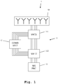
- the device 1 comprises an antenna array 10, which is connected to a switching unit 11, which again is connected to a combiner/splitter unit 12 and a signal processing unit 13.
- the switching unit 11 may be comprised by a first switching unit 111 and a second switching unit 112.
- the antenna array 10 therein comprises a plurality of individual antenna arrays. Plurality is to be understood as at least two antenna elements.
- the antenna array 10 is connected to the first switching unit 111, which is further connected to the combiner/splitter unit 12 and the second switching unit 112.
- the second switching unit 112 is also connected to the combiner/splitter unit 12 and to the signal processing unit 13.
- the connections between the different units 10-13 are fashioned so that individual channels corresponding to the antenna elements of the antenna array 10 are retained.
- This means that the antenna array 10 is connected to the first switching unit 111 by a number N of lines corresponding to the number N of antenna elements of the antenna array 10.
- the first switching unit 111 is connected to the combiner/splitter unit 12 also with N lines.
- the first switching unit 111 is connected to the second switching unit 112 also by a number N of lines.
- the combiner/splitter unit 12 is connected to the second switching unit 112 by N lines.
- the second switching unit 112 is connected to the signal processing unit 13 by N lines.
- the antenna array 10 can additionally comprise phase shifters, for introducing an individual phase shift of the antenna elements. Alternatively, this phase shift can be introduced in the signal processing unit 13.
- the device 1 can be configured into different modes: A broadband mode and a spatial resolution mode.
- the antenna array 10 is connected to the signal processing unit 13 via the combiner/splitter unit 12 by the switching unit 11. In detail, this is done by the first switching unit 111 connecting the antenna array 10 to the combiner/splitter unit 12 and the second switching unit 112 connecting the combiner/splitter unit 12 to the signal processor unit 13.
- the antenna array 10 is directly connected to the signal processing unit 13 by the switching unit 11. In detail, this is done by the first switching unit 111 connecting the antenna array 10 to the second switching unit 112, and the second switching unit 112 connecting the first switching unit 111 to the signal processing unit 13. This means that in spatial resolution mode, the combiner/splitter unit 12 is not connected to the signal path.
- the combiner/splitter unit 12 combines the individual antenna element signals of the antenna array 10 and provides them to the second switching unit 112. It should be noted that the combiner/splitter unit 12 provides the output signal on the same number of output lines, as input lines. Therefore, the second switching unit 112 receives an identical combined signal on N lines. This signal is then routed by the second switching unit 112 to the signal processing unit 13, which processes the N identical signals. Especially, the signal processing unit 13 can process different frequency slices on the different channels, thereby achieving an especially high bandwidth.
- the signal processing unit 13 When transmitting a signal in broadband mode, the signal processing unit 13 provides a plurality of N individual transmission signals, which can for example be N different frequency slices of a signal to be transmitted. These individual signals to be transmitted are routed by the second switching unit 112 to the combiner/splitter unit 12, which then combines them to a single signal to be transmitted. This single signal then is again split to N identical output signals, which are routed by the first switching unit 111 to the individual antenna elements of the antenna array 10. The individual antenna elements then emit the electromagnetic signal.
- N individual transmission signals can for example be N different frequency slices of a signal to be transmitted.
- These individual signals to be transmitted are routed by the second switching unit 112 to the combiner/splitter unit 12, which then combines them to a single signal to be transmitted. This single signal then is again split to N identical output signals, which are routed by the first switching unit 111 to the individual antenna elements of the antenna array 10. The individual antenna elements then emit the electromagnetic signal.
- each antenna element of the antenna array 10 When receiving a signal in spatial resolution mode, each antenna element of the antenna array 10 receives an individual signal.
- the antenna array can comprise a phase shifter for each of the antenna elements.
- the individual received antenna element signals are routed by the first switching unit 111 to the second switching unit 112, which routes them directly to the signal processor 13, circumventing the combiner/splitter unit 12.
- the signal processor unit 13 then individually processes the individual antenna element reception signals, retaining the spatial resolution information.
- the signal processing unit 13 When transmitting a signal in spatial resolution mode, the signal processing unit 13 provides a plurality of N individual signals to be transmitted.
- the individual signals to be transmitted can already be provided by the signal processing unit 13 with a phase shift in order to achieve a spatial resolution, e.g. a beamforming.
- the resulting individual signals to be transmitted are handed to the second switching unit 112 which routes them to the first switching unit 111, which again routes them to the individual antenna elements of the antenna array 10.
- the necessary phase shift for achieving the spatial resolution has not been introduced by the signal processing unit 13, it may be introduced by phase shifters within the antenna array 10. Further details of the switching unit 11 and the combiner/splitter unit 12 are shown along FIG. 2 and FIG. 3 .
- FIG. 2 a detailed block diagram of the switching unit 11 and the combiner/splitter unit 12 are shown.
- the switching unit 11 comprises a first switching unit 111 and a second switching unit 112.
- the antenna array 10 shown in FIG. 1 comprises four antenna elements, which are connected to four individual switches 11a1, 11b1, 11c1 and 11d1 of the first switching unit 111. This forms four signal paths 11a, 11b, 11c and 11d.
- the first switches 11a1-11d1 are connected to second switches 11a2, 11b2, 11c2, 11d2 of the second switching unit 112 through a dedicated line, each.
- the first switches 11a1-11d1 are connected to the combiner/splitter unit 12, which again is connected to the second switches 11a2-11d2.
- the first switches 11a1-11d1 as well as the second switches 11a2-11d2 all may switch at the same time. This means that all switches are either in the position shown here in FIG. 2 or in the position shown in FIG. 6 .
- the combiner/splitter unit 12 consists of three Wilkinson combiners 12a, 12b and 12c.
- the Wilkinson combiner 12a combines the signal of the switches 11a1 and 11b1 and routes the resulting signal to the Wilkinson combiner 12c.
- the Wilkinson combiner 12b combines the signals of the switches 11c1 and 11d1 and routes a resulting signal to the Wilkinson combiner 12c.
- the Wilkinson combiner 12c combines the signals, which are then split to the second switches 11a2-11d2. It is important to note that the specific construction of the combiner/splitter unit 12 is not to be understood as fixed. Also, a different structure of combiners and splitters can be used.
- signals provided on the side of the second switches 11a2-11d2 are combined and provided as an identical signal to all of the first switches 11a1-11d1, and that signals provided on the side of the first switches 11a1-11d1 are combined and provided as identical signals to each of the second switches 11a2-11d2.
- the combiner/splitter unit 12 is not connected to the signal paths 11a-11d. This corresponds to the spatial resolution mode, as described earlier.
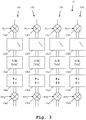
- FIG. 3 a detail of a further embodiment of the inventive device 1 is shown. Especially here, a detail of the signal processing unit 13 is shown.
- the signal paths 13a-13d each comprise a first mixer 13a1, 13b1, 13c1 and 13d1, connected to the switching unit 12.
- a filter 13a2, 13b2, 13c2, 13d2 in each signal path 13a-13d.
- the filters 13a2-13d2 are analog-digital converters and/or digital-analog converters 13a3, 13b3, 13c3, 13d3.
- Connected to these are second mixers 13a5, 13b5, 13c5, 13d5.
- the signal processing unit 13 does not necessarily have to comprise all of the units displayed here. In a most simple construction, the signal processing unit 13 merely comprises an analog-digital converter/digital-analog converter for each of the signal paths 13a-13d. In the following though, the embodiment as displayed in FIG. 3 is described in greater detail. Dependent upon the operation mode, the first mixers 13a1-13d1 and the second mixers 13a5-13d5 are provided with different signals.
- the switching unit 12 When receiving a signal in broadband mode, identical signals are provided by the switching unit 12 to the signal paths 13a-13d. These signals are mixed with local oscillator signals lo 0 , lo 1 , lo 2 and lo 3 by the first mixers 13a1-13d1.
- the first mixers 13a1-13d1 are I/Q-mixers, thereby resulting in a I-output signal and a Q-output signal, each.
- the resulting I/Q signals are handed to the filters 13a2-13d2, which perform a filtering, to limit the bandwidth of the individual signal.
- the resulting I/Q signals are handed to the analog-digital converters and/or digital-analog converters 13a3-13d3, which digitize the analog signals using a sampling frequency f S .
- the resulting digital I/Q signals are handed to the upsamplers/downsamplers 13a4-13d4, which increase the sampling rate, for example by the factor 4.
- the resulting digital upsampled I/Q signals are handed to the second mixers 13a5-13d5, which perform an additional mixing with signals nco 0 , nco 1 , nco 2 and nco 3 .
- This frequency constellation can also be seen in FIG. 5 .
- the resulting digital I/Q signals after the mixing are therefore frequency shifted achieving a high bandwidth of reception.
- Digital I/Q signals which each cover a specific different frequency slice of a combined output signal, are provided to the second mixers 13a5-13d5, which mix them with the signals nco 0 -nco 3 achieving the desired frequency shift, so that the output signals form a high bandwidth combined output signal.
- the signals are then provided to the upsamplers/downsamplers 13a4-13d4, which perform a downsampling, for example with the factor 4.
- the resulting downsampled signals are handed to the analog-digital converters and/or digital-analog converters 13a3-13d3, which generate analog signals from the digital signals.
- the combiner/splitter unit 12 When receiving a signal in spatial resolution mode, the combiner/splitter unit 12 as described earlier is circumvented by the switching unit 11.
- the individual antenna element reception signals are directly handed to the signal path 13a-13d of the signal processing unit 13.
- Each of the signals is handled individually.
- the first mixers 13a1-13d1 perform a mixing with the signals lo 0 -lo 3 after which a filtering by the filters 13a2-13d2 is performed.
- an upsampling for example by a factor of 4 is performed by the upsamplers/downsamplers 13a4-13d4.
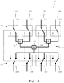
- FIG. 4 the same circuit diagram as in FIG. 2 is shown. Here, though, the active circuit elements in broadband mode are highlighted, while the passive circuit elements are shown as dashed lines. It can readily be seen that the combiner/splitter unit 12 is active in the broadband mode, shown here.
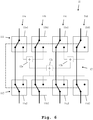
- the active circuit elements in spatial resolution mode are highlighted while the passive circuit elements are shown as dashed lines. It can be readily seen that the switching unit 11 circumvents the combiner/splitter unit 12 in the signal paths 11a-11d.
- the identical narrow bandwidth of the individual antenna element signals in spatial resolution mode is shown in FIG. 7 .
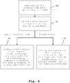
- a flow diagram In a first step 100, one of a broadband mode and a spatial resolution mode is selected. In a second step 101, a switching unit is set to a specific setting for the mode selected in step 100. In case of spatial resolution mode being selected, received signals and/or signals to be transmitted are routed on a signal path from an antenna array comprising a plurality of N antenna elements to a signal processing unit in a third step 102. Alternatively, if broadband mode has been selected in step 100, received signals and/or signals to be transmitted are routed on a signal path from the antenna array to a combiner/splitter unit to the signal processing unit, in a fourth step 103.
- the invention is not limited by the examples and especially not by a specific number of signal paths and antenna elements. Also, a limitation to a specific type of combiner/splitter unit is not intended.
- the invention discussed above can also be applied to a plurality of different communication schemes, such as mobile telephone communication, satellite telephony, etc.. The characteristics of the exemplary embodiments can be used in any advantageous combination.
Landscapes
- Engineering & Computer Science (AREA)
- Computer Networks & Wireless Communication (AREA)
- Signal Processing (AREA)
- Variable-Direction Aerials And Aerial Arrays (AREA)
Abstract
Description
- The invention relates to transmitting and/or receiving signals through an antenna array.
- During recent years, the use of antenna arrays for transmitting and receiving electromagnetic signals has come to widespread use. A common application of an antenna array is beamforming, where phase differences of individual antenna elements of the antenna array are used to achieve a spatial resolution. For example, the
US 2018/076869 A1 shows such a beamforming antenna array. - The individual transmission/reception paths of the individual antenna elements of such antenna arrays though have only a small bandwidth. This leads to a low bandwidth of the entire system. A reduced flexibility is the consequence.
- The object of the invention is to provide a device for transmitting and/or receiving electromagnetic signals with an increased flexibility. Moreover, the object is to provide an according method.
- The object is solved by the features of the first independent claim for the device and by the features of the second independent claim for the method. Further, it is solved by the features of an associated computer program claim. The dependent claims contain further developments.
- An inventive device for transmitting and/or receiving electromagnetic signals comprises an antenna array, comprising a plurality of N antenna elements, adapted to transmit and/or receive electromagnetic signals, a combiner/splitter unit, a signal processing unit, comprising at least one analog-digital converter and/or digital-analog converter for each of the antenna elements of the antenna array, and a switching unit, adapted to switch between a broadband mode and a spatial resolution mode. This allows for a spatial resolution in spatial resolution mode and a high bandwidth in broadband mode.
- Advantageously and preferably, the switching unit comprises a first switching unit and a second switching unit. The first switching unit is connected to the antenna array, the combiner/splitter unit and the second switching unit. The first switching unit is adapted to switch the antenna array between one of the combiner/splitter unit and the second switching unit. The second switching unit is connected to the combiner/splitter unit, the first switching unit and the signal processing unit. The second switching unit is then adapted to switch the signal processing unit between one of the combiner/splitter unit and the first switching unit. This allows for a very simple construction of the switching unit.
- Further advantageously and preferably, in broadband mode, the first switching unit is adapted to connect the antenna array to the combiner/splitter unit and the second switching unit is adapted to connect the combiner/splitter unit to the signal processing unit. Additionally, or alternatively, in spatial resolution mode, the first switching unit is adapted to connect the antenna array to the second switching unit and the second switching unit is adapted to connect the first switching unit to the signal processing unit. This allows for a very simple implementation of the broadband mode and the spatial resolution mode.
- Advantageously and preferably, the combiner/splitter unit comprises a plurality of N first ports and a plurality of N second ports. The combiner/splitter unit is adapted to combine input signals at the plurality of N first ports to a single output signal at the plurality of N second ports. Additionally, or alternatively, it is adapted to provide a single input signal present at the plurality of N second ports to the plurality of N first ports. This allows for a very simple signal combining and splitting.
- Advantageously and preferably, the first switching unit comprises a plurality of N switches. The second switching unit also comprises a plurality of N switches. The signal processing unit moreover comprises a plurality of N signal paths. Each of the plurality of N switches of the first switching unit is then connected to one of the antenna elements of the antenna array, one of the plurality of N first ports of the combiner/splitter unit, and one of the plurality of N switches of the second switching unit. Each of the plurality of N switches of the second switching unit is connected to one of the plurality of N switches of the first switching unit, one of the plurality of N second ports of the combiner/splitter unit, and one of the plurality of N signal paths of the signal processing unit. This allows for a very simple construction of the switching units.
- Advantageously and preferably, in broadband mode, the plurality of N switches of the first switching unit is adapted to connect the plurality of N antenna elements of the antenna array to the plurality of N first ports of the combiner/splitter unit. Moreover, in broadband mode, the plurality of N switches of the second switching unit is adapted to connect the plurality of N second ports of the combiner/splitter unit to the plurality of N signal paths of the signal processing unit. Additionally, or alternatively, in spatial resolution mode, the plurality of N switches of the first switching unit is adapted to connect the plurality of N antenna elements of the antenna array to the plurality of N switches of the second switching unit. Additionally, in this case, the plurality of N switches of the second switching unit is adapted to connect the plurality of N switches of the first switching unit to the plurality of N signal paths of the signal processing unit. This allows for an especially simple implementation of the broadband mode and the spatial resolution mode.
- Advantageously and preferably, each of the plurality of N signal paths of the signal processing unit is adapted to, when the device is receiving an electromagnetic signal in broadband mode, process a reception of a different frequency slice of the received electromagnetic signal, and when the device is transmitting an electromagnetic signal in broadband mode, generate a different frequency slice of the electromagnetic signal to be transmitted. This allows for a very simple implementation of the broadband mode.
- Alternatively and preferably, each of the plurality of N signal paths of the signal processing unit is adapted to, when the device is receiving an electromagnetic signal in spatial resolution mode, process a reception of a different antenna element reception signal, and when the device is transmitting an electromagnetic signal in spatial resolution mode, generate a different antenna element signal to be transmitted. This allows for a very simple implementation of the spatial resolution mode.
- Advantageously and preferably, each signal path of the signal processing unit comprises a first mixer and/or a filter and/or the before-mentioned analog-digital converter and/or digital-analog converter for each of the antenna elements of the antenna array and/or an upsampler and/or a downsampler and/or a second mixer. This allows for a very simple implementation of further processing by the signal processing unit.
- Advantageously and preferably, the device is a transceiver, adapted to transmit and receive electromagnetic signals. The plurality of N antenna elements is then adapted to transmit and receive electromagnetic signals. The combiner/splitter unit is then adapted to combine input signals at the plurality of N first ports to a single output signal at the plurality of N second ports and provide a single input signal present at plurality of N second ports to the plurality of N first ports. The signal processing unit is then adapted to generate signals to be transmitted by the antenna array and receive signals received by the antenna array as electromagnetic signals.
- This allows for an especially flexible use of the device. Alternatively, the device is only a receiver, adapted to receive electromagnetic signals. The plurality of N antenna elements is then adapted to receive electromagnetic signals. The combiner/splitter unit is then adapted to combine input signals at the plurality of N first ports to a single output signal at the plurality of N second ports. The signal processing unit is then adapted to receive signals received by the antenna array as electromagnetic signals. This allows for a reduction of complexity and comparison to the transceiver.
- Alternatively and preferably, the device is merely a transmitter, adapted to transmit electromagnetic signals. The plurality of N antenna elements is then adapted to transmit electromagnetic signals. The combiner/splitter unit is then adapted to provide a single input signal present at the plurality of N second ports to the plurality of N first ports. The signal processing unit is then adapted to generate signals to be transmitted by the antenna array. This allows for a reduction of complexity with regard to the transceiver.
- Advantageously and preferably, N is at least 2, or at least 3, or at least 4, or at least 5, or at least 6, or at least 7, or at least 8, or at least 9, or at least 10, or at least 16, or at least 32, or at least 64, or at least 128, or at least 256, or at least 512, or at least 1024. This allows for a very flexible use of the antenna array.
- An inventive method for transmitting and receiving electromagnetic signals comprises selecting one of a broadband mode and a spatial resolution mode, setting a switching unit to a specific setting for the selected mode, routing received signals and/or signals to be transmitted on a signal path from an antenna array comprising a plurality of N antenna elements, to a signal processing unit, in spatial resolution mode, and routing received signals and/or signals to be transmitted on a signal path from the antenna array to a combiner/splitter unit, to the signal processing unit, in broadband mode. This allows for a spatial resolution in spatial resolution mode and a high bandwidth in broadband mode.
- An inventive computer program comprises program code for performing the previously described method, when the computer program runs on a computer or a digital signal processor. This allows for a spatial resolution in spatial resolution mode and a high bandwidth in broadband mode.
- An exemplary embodiment of the invention is now further explained with respect to the drawings by way of examples only, in which
- FIG. 1
- shows a first embodiment of the inventive device in a block diagram;
- FIG. 2
- shows a detail of a second embodiment of the inventive device in a block diagram;
- FIG. 3
- shows a detail of a third embodiment of the inventive device in a block diagram;
- FIG. 4
- shows one mode of operation of a fourth embodiment of the inventive device;
- FIG. 5
- shows exemplary signals within a fifth embodiment of the inventive device;
- FIG. 6
- shows a further mode of operation of a sixth embodiment of the inventive device;
- FIG. 7
- shows an exemplary signal in a seventh embodiment of the inventive device, and
- FIG. 8
- shows an exemplary embodiment of the inventive method in a flow diagram.
- First, we demonstrate the general function and construction of different embodiments of the inventive device along
FIG. 1 - FIG. 3 . With regard toFIG. 4 - FIG. 7 , further details of the operation of different embodiments of the inventive device are shown. Finally, alongFIG. 8 , the function of an embodiment of the inventive method is described in detail. Similar entities and reference numbers in different figures have been partially omitted. - In
FIG. 1 , a first embodiment of theinventive device 1 is shown. Theinventive device 1 may either be a transceiver, or a receiver, or a transmitter. - The
device 1 comprises anantenna array 10, which is connected to aswitching unit 11, which again is connected to a combiner/splitter unit 12 and asignal processing unit 13. Especially, the switchingunit 11 may be comprised by afirst switching unit 111 and asecond switching unit 112. Theantenna array 10 therein comprises a plurality of individual antenna arrays. Plurality is to be understood as at least two antenna elements. - In detail, the
antenna array 10 is connected to thefirst switching unit 111, which is further connected to the combiner/splitter unit 12 and thesecond switching unit 112. Thesecond switching unit 112 is also connected to the combiner/splitter unit 12 and to thesignal processing unit 13. - The connections between the different units 10-13 are fashioned so that individual channels corresponding to the antenna elements of the
antenna array 10 are retained. This means that theantenna array 10 is connected to thefirst switching unit 111 by a number N of lines corresponding to the number N of antenna elements of theantenna array 10. Thefirst switching unit 111 is connected to the combiner/splitter unit 12 also with N lines. Thefirst switching unit 111 is connected to thesecond switching unit 112 also by a number N of lines. Further, the combiner/splitter unit 12 is connected to thesecond switching unit 112 by N lines. Also, thesecond switching unit 112 is connected to thesignal processing unit 13 by N lines. - The
antenna array 10 can additionally comprise phase shifters, for introducing an individual phase shift of the antenna elements. Alternatively, this phase shift can be introduced in thesignal processing unit 13. - The
device 1 can be configured into different modes: A broadband mode and a spatial resolution mode. - In broadband mode, the
antenna array 10 is connected to thesignal processing unit 13 via the combiner/splitter unit 12 by the switchingunit 11. In detail, this is done by thefirst switching unit 111 connecting theantenna array 10 to the combiner/splitter unit 12 and thesecond switching unit 112 connecting the combiner/splitter unit 12 to thesignal processor unit 13. - In spatial resolution mode, the
antenna array 10 is directly connected to thesignal processing unit 13 by the switchingunit 11. In detail, this is done by thefirst switching unit 111 connecting theantenna array 10 to thesecond switching unit 112, and thesecond switching unit 112 connecting thefirst switching unit 111 to thesignal processing unit 13. This means that in spatial resolution mode, the combiner/splitter unit 12 is not connected to the signal path. - Therefore, when receiving a signal in broadband mode, all antenna elements of the
antenna array 10 receive a similar signal, since theantenna array 10 does not introduce a phase shift, as used to achieve a spatial resolution. The individual antenna element signals are routed to the combiner/splitter unit 12 by thefirst switching unit 111. The combiner/splitter unit 12 combines the individual antenna element signals of theantenna array 10 and provides them to thesecond switching unit 112. It should be noted that the combiner/splitter unit 12 provides the output signal on the same number of output lines, as input lines. Therefore, thesecond switching unit 112 receives an identical combined signal on N lines. This signal is then routed by thesecond switching unit 112 to thesignal processing unit 13, which processes the N identical signals. Especially, thesignal processing unit 13 can process different frequency slices on the different channels, thereby achieving an especially high bandwidth. - When transmitting a signal in broadband mode, the
signal processing unit 13 provides a plurality of N individual transmission signals, which can for example be N different frequency slices of a signal to be transmitted. These individual signals to be transmitted are routed by thesecond switching unit 112 to the combiner/splitter unit 12, which then combines them to a single signal to be transmitted. This single signal then is again split to N identical output signals, which are routed by thefirst switching unit 111 to the individual antenna elements of theantenna array 10. The individual antenna elements then emit the electromagnetic signal. - When receiving a signal in spatial resolution mode, each antenna element of the
antenna array 10 receives an individual signal. Especially for this case, the antenna array can comprise a phase shifter for each of the antenna elements. The individual received antenna element signals are routed by thefirst switching unit 111 to thesecond switching unit 112, which routes them directly to thesignal processor 13, circumventing the combiner/splitter unit 12. Thesignal processor unit 13 then individually processes the individual antenna element reception signals, retaining the spatial resolution information. - When transmitting a signal in spatial resolution mode, the
signal processing unit 13 provides a plurality of N individual signals to be transmitted. The individual signals to be transmitted can already be provided by thesignal processing unit 13 with a phase shift in order to achieve a spatial resolution, e.g. a beamforming. The resulting individual signals to be transmitted are handed to thesecond switching unit 112 which routes them to thefirst switching unit 111, which again routes them to the individual antenna elements of theantenna array 10. In case the necessary phase shift for achieving the spatial resolution has not been introduced by thesignal processing unit 13, it may be introduced by phase shifters within theantenna array 10. Further details of the switchingunit 11 and the combiner/splitter unit 12 are shown alongFIG. 2 andFIG. 3 . - In
FIG. 2 , a detailed block diagram of the switchingunit 11 and the combiner/splitter unit 12 are shown. The switchingunit 11 comprises afirst switching unit 111 and asecond switching unit 112. InFIG. 2 , a case of N=4 is shown. This means that theantenna array 10 shown inFIG. 1 comprises four antenna elements, which are connected to four individual switches 11a1, 11b1, 11c1 and 11d1 of thefirst switching unit 111. This forms foursignal paths second switching unit 112 through a dedicated line, each. Moreover, the first switches 11a1-11d1 are connected to the combiner/splitter unit 12, which again is connected to the second switches 11a2-11d2. - The first switches 11a1-11d1 as well as the second switches 11a2-11d2 all may switch at the same time. This means that all switches are either in the position shown here in
FIG. 2 or in the position shown inFIG. 6 . - In the embodiment shown here, the combiner/
splitter unit 12 consists of threeWilkinson combiners Wilkinson combiner 12a combines the signal of the switches 11a1 and 11b1 and routes the resulting signal to theWilkinson combiner 12c. TheWilkinson combiner 12b combines the signals of the switches 11c1 and 11d1 and routes a resulting signal to theWilkinson combiner 12c. TheWilkinson combiner 12c combines the signals, which are then split to the second switches 11a2-11d2. It is important to note that the specific construction of the combiner/splitter unit 12 is not to be understood as fixed. Also, a different structure of combiners and splitters can be used. It is preferred that signals provided on the side of the second switches 11a2-11d2 are combined and provided as an identical signal to all of the first switches 11a1-11d1, and that signals provided on the side of the first switches 11a1-11d1 are combined and provided as identical signals to each of the second switches 11a2-11d2. - In a first switch setting, as shown here, the combiner/
splitter unit 12 is not connected to thesignal paths 11a-11d. This corresponds to the spatial resolution mode, as described earlier. - In
FIG. 3 , a detail of a further embodiment of theinventive device 1 is shown. Especially here, a detail of thesignal processing unit 13 is shown. Thesignal processing unit 13 comprises fourindividual signal paths antenna array 10 ofFIG. 1 is shown. - The
signal paths 13a-13d each comprise a first mixer 13a1, 13b1, 13c1 and 13d1, connected to theswitching unit 12. Connected to the first mixers is a filter 13a2, 13b2, 13c2, 13d2 in eachsignal path 13a-13d. Connected to the filters 13a2-13d2 are analog-digital converters and/or digital-analog converters 13a3, 13b3, 13c3, 13d3. Connected to these are upsamplers/downsamplers 13a4, 13b4, 13c4, 13d4. Connected to these are second mixers 13a5, 13b5, 13c5, 13d5. - It is worth to be noted that the
signal processing unit 13 does not necessarily have to comprise all of the units displayed here. In a most simple construction, thesignal processing unit 13 merely comprises an analog-digital converter/digital-analog converter for each of thesignal paths 13a-13d. In the following though, the embodiment as displayed inFIG. 3 is described in greater detail. Dependent upon the operation mode, the first mixers 13a1-13d1 and the second mixers 13a5-13d5 are provided with different signals. - When receiving a signal in broadband mode, identical signals are provided by the switching
unit 12 to thesignal paths 13a-13d. These signals are mixed with local oscillator signals lo0, lo1, lo2 and lo3 by the first mixers 13a1-13d1. In this embodiment, the first mixers 13a1-13d1 are I/Q-mixers, thereby resulting in a I-output signal and a Q-output signal, each. The resulting I/Q signals are handed to the filters 13a2-13d2, which perform a filtering, to limit the bandwidth of the individual signal. The resulting I/Q signals are handed to the analog-digital converters and/or digital-analog converters 13a3-13d3, which digitize the analog signals using a sampling frequency fS. The resulting digital I/Q signals are handed to the upsamplers/downsamplers 13a4-13d4, which increase the sampling rate, for example by thefactor 4. The resulting digital upsampled I/Q signals are handed to the second mixers 13a5-13d5, which perform an additional mixing with signals nco0, nco1, nco2 and nco3. - The signals provided to the first mixers 13a1-13d1 are given as follows:


- The frequencies of the signals provided to the second mixers 13a5-13d5 are given as follows:


- Therein,

- This frequency constellation can also be seen in
FIG. 5 . The resulting digital I/Q signals after the mixing are therefore frequency shifted achieving a high bandwidth of reception. - When transmitting a signal in broadband mode, the reverse direction is followed. Digital I/Q signals, which each cover a specific different frequency slice of a combined output signal, are provided to the second mixers 13a5-13d5, which mix them with the signals nco0-nco3 achieving the desired frequency shift, so that the output signals form a high bandwidth combined output signal. The signals are then provided to the upsamplers/downsamplers 13a4-13d4, which perform a downsampling, for example with the
factor 4. The resulting downsampled signals are handed to the analog-digital converters and/or digital-analog converters 13a3-13d3, which generate analog signals from the digital signals. These are filtered by the filters 13a2-13d2 and again mixed with the signals lo0-lo3, achieving frequency slice output signals, which are then routed through the combiner/splitter unit 12 to be transmitted by the antenna elements of theantenna array 10 as a combined output signal. - When receiving a signal in spatial resolution mode, the combiner/
splitter unit 12 as described earlier is circumvented by the switchingunit 11. The individual antenna element reception signals are directly handed to thesignal path 13a-13d of thesignal processing unit 13. Each of the signals is handled individually. Especially, the first mixers 13a1-13d1 perform a mixing with the signals lo0-lo3 after which a filtering by the filters 13a2-13d2 is performed. After digitization by the analog-digital converters and/or digital-analog converters 13a3-13d3, an upsampling, for example by a factor of 4 is performed by the upsamplers/downsamplers 13a4-13d4. Finally, a further mixing with the signals nco0-nco3 by the second mixers 13a5-13d5 is performed. The individual antenna element signals are processed within the same narrow bandwidth. By either introducing a phase shift within theantenna array 10 or by digitally introducing a phase shift, not shown here, the spatial resolution, e.g. beamforming is achieved. - When transmitting a signal in spatial resolution mode, individual digital I/Q signals to be transmitted are provided to the second mixers 13a5-13d5 and are mixed with the signals nco0-nco3. After a downsampling by the upsamplers/downsamplers 13a4-13d4, the signals are converted to analog signals by the analog-digital converters/digital-analog converters 13a3-13d3 and are then filtered by filters 13a2-13d2. After a final mixing with the signals lo0-lo3 by the mixers 13a1-13d1, the signals are handed to the
switching unit 12, which routes them directly to the individual antenna elements of theantenna array 10 to be transmitted. Also, here, the phase shift necessary for achieving the spatial resolution is achieved by either providing the original signals to be transmitted already including the phase shift, or by introducing the phase shift using phase shifters within theantenna array 10. - In
FIG. 4 , the same circuit diagram as inFIG. 2 is shown. Here, though, the active circuit elements in broadband mode are highlighted, while the passive circuit elements are shown as dashed lines. It can readily be seen that the combiner/splitter unit 12 is active in the broadband mode, shown here. - The resulting bandwidth of the individual partial signals can be seen in
Fig. 5 . - Moreover, in
FIG. 6 , the active circuit elements in spatial resolution mode are highlighted while the passive circuit elements are shown as dashed lines. It can be readily seen that the switchingunit 11 circumvents the combiner/splitter unit 12 in thesignal paths 11a-11d. - The identical narrow bandwidth of the individual antenna element signals in spatial resolution mode is shown in
FIG. 7 . - Finally, in
FIG. 8 , an embodiment of the inventive method is shown in a flow diagram. In afirst step 100, one of a broadband mode and a spatial resolution mode is selected. In asecond step 101, a switching unit is set to a specific setting for the mode selected instep 100. In case of spatial resolution mode being selected, received signals and/or signals to be transmitted are routed on a signal path from an antenna array comprising a plurality of N antenna elements to a signal processing unit in athird step 102. Alternatively, if broadband mode has been selected instep 100, received signals and/or signals to be transmitted are routed on a signal path from the antenna array to a combiner/splitter unit to the signal processing unit, in afourth step 103. - It is important to note that the inventive device and method very closely correspond. Therefore, all of the above said regarding the device is also applicable to the method. Everything which is described in the description and/or claimed in the claims and/or drawn in the drawings can be combined.
- The invention is not limited by the examples and especially not by a specific number of signal paths and antenna elements. Also, a limitation to a specific type of combiner/splitter unit is not intended. The invention discussed above can also be applied to a plurality of different communication schemes, such as mobile telephone communication, satellite telephony, etc.. The characteristics of the exemplary embodiments can be used in any advantageous combination.
Claims (15)
- Device for transmitting and/or receiving electromagnetic signals, comprising:- an antenna array (10), comprising a plurality of N antenna elements, adapted to transmit and/or receive electromagnetic signals,- a combiner/splitter unit (12),- a signal processing unit (13), comprising at least one analog-digital-converter and/or digital-analog-converter (13a3, 13b3, 13c3, 13d3) for each of the antenna elements of the antenna array (10), and- a switching unit (11), adapted to switch between a broadband mode and a spatial resolution mode.
- Device according to claim 1,
wherein the switching unit (11) comprises a first switching unit (111) and a second switching unit (112), wherein the first switching unit (111) is connected to the antenna array (10), the combiner/splitter unit (12), and the second switching unit (112),
wherein the first switching unit (111) is adapted to switch the antenna array (10) between one of the combiner/splitter unit (12) and the second switching unit (112),
wherein the second switching unit (112) is connected to the combiner/splitter unit (12), the first switching unit (111), and the signal processing unit (13), and
wherein the second switching unit (112) is adapted to switch the signal processing unit (13) between one of the combiner/splitter unit and the first switching unit (111). - Device according to claim 2,
wherein in broadband mode,- the first switching unit (111) is adapted to connect the antenna array (10) to the combiner/splitter unit (12), and- the second switching unit (112) is adapted to connect the combiner/splitter unit (12) to the signal processing unit (13), and/orwherein in spatial resolution mode,- the first switching unit (111) is adapted to connect the antenna array (10) to the second switching unit (112), and- the second switching unit (112) is adapted to connect the first switching unit (111) to the signal processing unit (13). - Device according to claim 2 or 3,
wherein the combiner/splitter unit (12) comprises a plurality of N first ports and a plurality of N second ports,
wherein the combiner/splitter unit (12) is adapted to- combine input signals at the plurality of N first ports to a single output signal at the plurality of N second ports, and/or- provide a single input signal present at the plurality of N second ports to the plurality of N first ports. - Device according to claim 4,
wherein the first switching unit (111) comprises a plurality of N switches (11a1, 11b1, 11c1, 11d1), wherein the second switching unit (112) comprises a plurality of N switches (11a2, 11b2, 11c2, 11d2),
wherein the signal processing unit (13) comprises a plurality of N signal paths (13a, 13b, 13c, 13d),
wherein each of the plurality of N switches (11a1, 11b1, 11c1, 11d1) of the first switching unit (111) is connected to- one of the antenna elements of the antenna array (10),- one of the plurality of N first ports of the combiner/splitter unit (12), and- one of the plurality of N switches (11a2, 11b2, 11c2, 11d2) of the second switching unit (112),wherein each of the plurality of N switches (11a2, 11b2, 11c2, 11d2) of the second switching unit (112) is connected to- one of the plurality of N switches (11a1, 11b1, 11c1, 11d1) of the first switching unit (111),- one of the plurality of N second ports of the combiner/splitter unit (12), and- one of the plurality of N signal paths (13a, 13b, 13c, 13d) of the signal processing unit (13). - Device according to claim 5,
wherein in broadband mode,- the plurality of N switches (11a1, 11b1, 11c1, 11d1) of the first switching unit (111) is adapted to connect the plurality of N antenna elements of the antenna array (10) to the plurality of N first ports of the combiner/splitter unit (12), and- the plurality of N switches (11a2, 11b2, 11c2, 11d2) of the second switching unit (112) is adapted to connect the plurality of N second ports of the combiner/splitter unit (12) to the plurality of N signal paths of the signal processing unit (13), and/orwherein in spatial resolution mode,- the plurality of N switches (11a1, 11b1, 11c1, 11d1) of the first switching unit (111) is adapted to connect the plurality of N antenna elements of the antenna array (10) to the plurality of N switches (11a2, 11b2, 11c2, 11d2) of the second switching unit (112), and- the plurality of N switches (11a2, 11b2, 11c2, 11d2) of the second switching unit (112) is adapted to connect the plurality of N switches (11a1, 11b1, 11c1, 11d1) of the first switching unit (111) to the plurality of N signal paths of the signal processing unit (13). - Device according to claim 5 or 6,
wherein each of the plurality of N signal paths (13a, 13b, 13c, 13d) of the signal processing unit (13) is adapted to,- when the device is receiving an electromagnetic signal in broadband mode, process a reception of a different frequency slice of the received electromagnetic signal, and- when the device is transmitting an electromagnetic signal in broadband mode, generate a different frequency slice of the electromagnetic signal to be transmitted. - Device according to any of the claims 5 to 7,
wherein each of the plurality of N signal paths (13a, 13b, 13c, 13d) of the signal processing unit (13) is adapted to,- when the device is receiving an electromagnetic signal in spatial resolution mode, process a reception of a different antenna element reception signal, and- when the device is transmitting an electromagnetic signal in spatial resolution mode, generate a different antenna element signal to be transmitted. - Device according to any of the claims 5 to 8,
wherein each signal path (13a, 13b, 13c, 13d) of the signal processing unit (13) comprises:- a first mixer (13a1, 13b1, 13c1, 13d1) and/or- a filter (13a2, 13b2, 13c2, 13d2), and/or- the analog-digital-converter and/or digital-analog-converter (13a3, 13b3, 13c3, 13d3) for each of the antenna elements of the antenna array (10), and/or- an upsampler and/or a downsampler (13a4, 13b4, 13c4, 13d4), and/or- a second mixer (13a5, 13b5, 13c5, 13d5). - Device according to any of the claims 1 to 9,
wherein the device (1) is a transceiver, adapted to transmit and receive electromagnetic signals,
wherein the plurality of N antenna elements are adapted to transmit and receive electromagnetic signals, and
wherein the combiner/splitter unit (12) is adapted to- combine input signals at the plurality of N first ports to a single output signal at the plurality of N second ports, and- provide a single input signal present at the plurality of N second ports to the plurality of N first ports, andwherein the signal processing unit (13) is adapted to generate signals to be transmitted by the antenna array (10) and to receive signals received by the antenna array (10) as electromagnetic signals. - Device according to any of the claims 1 to 9,
wherein the device (1) is a receiver, adapted to receive electromagnetic signals,
wherein the plurality of N antenna elements is adapted to receive electromagnetic signals, and
wherein the combiner/splitter unit (12) adapted to combine input signals at the plurality of N first ports to a single output signal at the plurality of N second ports, and
wherein the signal processing unit (13) is adapted receive signals received by the antenna array (10) as electromagnetic signals. - Device according to any of the claims 1 to 9,
wherein the device (1) is a transmitter, adapted to transmit electromagnetic signals,
wherein the plurality of N antenna elements are adapted to transmit electromagnetic signals, and
wherein the combiner/splitter unit (12) is adapted to provide a single input signal present at the plurality of N second ports to the plurality of N first ports, and wherein the signal processing unit (13) is adapted to generate signals to be transmitted by the antenna array (10) . - Device according to any of the claims 1 to 12, wherein N is at least 2, or at least 3, or at least 4, or at least 5, or at least 6, or at least 7, or at least 8, or at least 9, or at least 10, or at least 16, or at least 32, or at least 64, or at least 128, or at least 256, or at least 512, or at least 1024.
- Method for transmitting and/or receiving electromagnetic signals, comprising:- selecting (100) one of a broadband mode and a spatial resolution mode,- setting (101) a switching unit (11) to a specific setting for the selected mode,- routing (102) received signals and/or signals to be transmitted on a signal path from an antenna array (10), comprising a plurality of N antenna elements, to a signal processing unit (13), in spatial resolution mode, and- routing (103) received signals and/or signals to be transmitted on a signal path from the antenna array (10) to a combiner/splitter unit (12) and to the signal processing unit (13) in broadband mode.
- A computer program with a program code for performing the method according to claim 14, when the computer program runs on a computer or a digital signal processor.
Priority Applications (3)
| Application Number | Priority Date | Filing Date | Title |
|---|---|---|---|
| EP18209050.6A EP3660981B8 (en) | 2018-11-29 | 2018-11-29 | Spatial and bandwidth multiplexing device and method |
| US16/233,391 US11245186B2 (en) | 2018-11-29 | 2018-12-27 | Spatial and bandwidth multiplexing device and method |
| CN201910031209.7A CN111245489B (en) | 2018-11-29 | 2019-01-14 | Space and bandwidth multiplexing device and method |
Applications Claiming Priority (1)
| Application Number | Priority Date | Filing Date | Title |
|---|---|---|---|
| EP18209050.6A EP3660981B8 (en) | 2018-11-29 | 2018-11-29 | Spatial and bandwidth multiplexing device and method |
Publications (3)
| Publication Number | Publication Date |
|---|---|
| EP3660981A1 true EP3660981A1 (en) | 2020-06-03 |
| EP3660981B1 EP3660981B1 (en) | 2021-04-28 |
| EP3660981B8 EP3660981B8 (en) | 2021-06-02 |
Family
ID=64559484
Family Applications (1)
| Application Number | Title | Priority Date | Filing Date |
|---|---|---|---|
| EP18209050.6A Active EP3660981B8 (en) | 2018-11-29 | 2018-11-29 | Spatial and bandwidth multiplexing device and method |
Country Status (3)
| Country | Link |
|---|---|
| US (1) | US11245186B2 (en) |
| EP (1) | EP3660981B8 (en) |
| CN (1) | CN111245489B (en) |
Families Citing this family (2)
| Publication number | Priority date | Publication date | Assignee | Title |
|---|---|---|---|---|
| US12183985B2 (en) * | 2021-12-02 | 2024-12-31 | Ruckus Ip Holdings Llc | Low-loss switchable panel antennas |
| KR102586162B1 (en) * | 2023-03-07 | 2023-10-05 | 국방과학연구소 | All-metal vivaldi antenna having band notch and operation frequency tunable characteristics and array antenna including the same |
Citations (3)
| Publication number | Priority date | Publication date | Assignee | Title |
|---|---|---|---|---|
| US6859189B1 (en) * | 2002-02-26 | 2005-02-22 | The United States Of America As Represented By The Secretary Of The Navy | Broadband antennas |
| US20110111708A1 (en) * | 2006-10-31 | 2011-05-12 | Palm, Inc. | Techniques to control a shared antenna architecture for multiple co-located radio modules |
| US20180076869A1 (en) | 2016-09-13 | 2018-03-15 | Corning Optical Communications Wireless Ltd | Antenna array beamforming in a remote unit(s) in a wireless distribution system (wds) |
Family Cites Families (10)
| Publication number | Priority date | Publication date | Assignee | Title |
|---|---|---|---|---|
| EP1533916A1 (en) * | 2003-11-18 | 2005-05-25 | Mitsubishi Electric Information Technology Centre Europe B.V. | Diversity switch combiner |
| JP4734210B2 (en) * | 2006-10-04 | 2011-07-27 | 富士通株式会社 | Wireless communication method |
| US8873585B2 (en) * | 2006-12-19 | 2014-10-28 | Corning Optical Communications Wireless Ltd | Distributed antenna system for MIMO technologies |
| EP2143214A2 (en) * | 2007-05-10 | 2010-01-13 | Astrium Limited | Signal processing system |
| US20110033011A1 (en) * | 2009-08-05 | 2011-02-10 | Industrial Technology Research Institute | Methods and apparatuses relating to multi-resolution transmissions with mimo scheme |
| US9490548B2 (en) * | 2013-02-26 | 2016-11-08 | Qualcomm Incorporated | Wireless device with antenna array and separate antenna |
| GB2516617B (en) * | 2013-06-12 | 2018-02-21 | Analog Devices Global | Communication unit or method for identifying a connectivity relationship between a logical channel and an antenna element of an active antenna system |
| US10419080B2 (en) * | 2016-01-27 | 2019-09-17 | RF DSP Inc. | Cellular wireless communication systems enhanced by intelligent self-organizing wireless distributed active antennas |
| US10141993B2 (en) * | 2016-06-16 | 2018-11-27 | Intel Corporation | Modular antenna array beam forming |
| EP3300256B1 (en) * | 2016-09-27 | 2021-06-02 | Rohde & Schwarz GmbH & Co. KG | Method for controlling digital-to-analogue converters and rf transmit circuit arrangement |
-
2018
- 2018-11-29 EP EP18209050.6A patent/EP3660981B8/en active Active
- 2018-12-27 US US16/233,391 patent/US11245186B2/en active Active
-
2019
- 2019-01-14 CN CN201910031209.7A patent/CN111245489B/en active Active
Patent Citations (3)
| Publication number | Priority date | Publication date | Assignee | Title |
|---|---|---|---|---|
| US6859189B1 (en) * | 2002-02-26 | 2005-02-22 | The United States Of America As Represented By The Secretary Of The Navy | Broadband antennas |
| US20110111708A1 (en) * | 2006-10-31 | 2011-05-12 | Palm, Inc. | Techniques to control a shared antenna architecture for multiple co-located radio modules |
| US20180076869A1 (en) | 2016-09-13 | 2018-03-15 | Corning Optical Communications Wireless Ltd | Antenna array beamforming in a remote unit(s) in a wireless distribution system (wds) |
Non-Patent Citations (1)
| Title |
|---|
| UTHANSAKUL M ET AL: "Design and Performance Assessment of a Wideband Smart Antenna Employing Only Spatial Signal Processing", ANTENNAS AND PROPAGATION SOCIETY INTERNATIONAL SYMPOSIUM 2006, IEEE ALBUQUERQUE, NM, USA 09-14 JULY 2006, PISCATAWAY, NJ, USA,IEEE, PISCATAWAY, NJ, USA, 9 July 2006 (2006-07-09), pages 2525 - 2528, XP010944407, ISBN: 978-1-4244-0123-9 * |
Also Published As
| Publication number | Publication date |
|---|---|
| CN111245489A (en) | 2020-06-05 |
| EP3660981B1 (en) | 2021-04-28 |
| US11245186B2 (en) | 2022-02-08 |
| US20200176868A1 (en) | 2020-06-04 |
| EP3660981B8 (en) | 2021-06-02 |
| CN111245489B (en) | 2024-02-27 |
Similar Documents
| Publication | Publication Date | Title |
|---|---|---|
| KR100593176B1 (en) | Analog baseband processor and signal processing method for multimode | |
| US8077760B2 (en) | Digital transponder with real signal channelizer and synthesizer | |
| USRE41797E1 (en) | Polyphase channelization system | |
| US10804943B2 (en) | Systems and methods for configurable hybrid self-interference cancellation | |
| US5579341A (en) | Multi-channel digital transceiver and method | |
| WO2003003613A1 (en) | Frequency offset diversity receiver | |
| JP2002535911A (en) | Improvements for duplex filtering | |
| US20100259433A1 (en) | Signal Processing System | |
| EP0800737B1 (en) | Multiple access digital transmitter and receiver | |
| EP3660981B1 (en) | Spatial and bandwidth multiplexing device and method | |
| US20240313808A1 (en) | High-performance filter bank channelizers | |
| JP5579273B2 (en) | Demultiplexing device, multiplexing device and relay device | |
| EP3244551B1 (en) | Antenna device | |
| GB2405061A (en) | Multirate digital transceiver | |
| US20190089054A1 (en) | Techniques and Methods for Adaptive Removal of Analog Phase Errors in Frequency Division Multiplexed Digital Beam-Formers | |
| CN115065376B (en) | Eight-channel high-power frequency conversion TR (transmitter-receiver) assembly | |
| US11581873B2 (en) | Dual mode digital filters for RF sampling transceivers | |
| KR101197854B1 (en) | Digital hybrid amplifier calibration and compensation method | |
| US20030069009A1 (en) | Cellular communications channelizer | |
| JP3762609B2 (en) | Communication device, frequency spectrum inversion calculation method, and program storage medium | |
| JP5814134B2 (en) | Array antenna | |
| CN101606333B (en) | Beamforming system and method | |
| JP2011029959A (en) | Frequency conversion device | |
| US20260051932A1 (en) | Hybrid Digital Delay Beamforming Circuits and Methods | |
| EP3868025A1 (en) | Transmitting/receiving device for a motor vehicle and motor vehicle having such a transmitting/receiving device |
Legal Events
| Date | Code | Title | Description |
|---|---|---|---|
| PUAI | Public reference made under article 153(3) epc to a published international application that has entered the european phase |
Free format text: ORIGINAL CODE: 0009012 |
|
| STAA | Information on the status of an ep patent application or granted ep patent |
Free format text: STATUS: REQUEST FOR EXAMINATION WAS MADE |
|
| 17P | Request for examination filed |
Effective date: 20190718 |
|
| AK | Designated contracting states |
Kind code of ref document: A1 Designated state(s): AL AT BE BG CH CY CZ DE DK EE ES FI FR GB GR HR HU IE IS IT LI LT LU LV MC MK MT NL NO PL PT RO RS SE SI SK SM TR |
|
| AX | Request for extension of the european patent |
Extension state: BA ME |
|
| GRAP | Despatch of communication of intention to grant a patent |
Free format text: ORIGINAL CODE: EPIDOSNIGR1 |
|
| STAA | Information on the status of an ep patent application or granted ep patent |
Free format text: STATUS: GRANT OF PATENT IS INTENDED |
|
| GRAS | Grant fee paid |
Free format text: ORIGINAL CODE: EPIDOSNIGR3 |
|
| INTG | Intention to grant announced |
Effective date: 20210219 |
|
| RIN1 | Information on inventor provided before grant (corrected) |
Inventor name: FEILEN, MICHAEL |
|
| GRAA | (expected) grant |
Free format text: ORIGINAL CODE: 0009210 |
|
| STAA | Information on the status of an ep patent application or granted ep patent |
Free format text: STATUS: THE PATENT HAS BEEN GRANTED |
|
| AK | Designated contracting states |
Kind code of ref document: B1 Designated state(s): AL AT BE BG CH CY CZ DE DK EE ES FI FR GB GR HR HU IE IS IT LI LT LU LV MC MK MT NL NO PL PT RO RS SE SI SK SM TR |
|
| REG | Reference to a national code |
Ref country code: GB Ref legal event code: FG4D |
|
| REG | Reference to a national code |
Ref country code: AT Ref legal event code: REF Ref document number: 1388163 Country of ref document: AT Kind code of ref document: T Effective date: 20210515 |
|
| RBV | Designated contracting states (corrected) |
Designated state(s): AL AT BE BG CY CZ DE DK EE ES FI FR GB GR HR HU IS IT LT LU LV MC MK MT NL NO PL PT RO RS SE SI SK SM TR |
|
| REG | Reference to a national code |
Ref country code: DE Ref legal event code: R096 Ref document number: 602018016137 Country of ref document: DE |
|
| REG | Reference to a national code |
Ref country code: IE Ref legal event code: FG4D |
|
| REG | Reference to a national code |
Ref country code: LT Ref legal event code: MG9D |
|
| REG | Reference to a national code |
Ref country code: AT Ref legal event code: MK05 Ref document number: 1388163 Country of ref document: AT Kind code of ref document: T Effective date: 20210428 |
|
| PG25 | Lapsed in a contracting state [announced via postgrant information from national office to epo] |
Ref country code: FI Free format text: LAPSE BECAUSE OF FAILURE TO SUBMIT A TRANSLATION OF THE DESCRIPTION OR TO PAY THE FEE WITHIN THE PRESCRIBED TIME-LIMIT Effective date: 20210428 Ref country code: LT Free format text: LAPSE BECAUSE OF FAILURE TO SUBMIT A TRANSLATION OF THE DESCRIPTION OR TO PAY THE FEE WITHIN THE PRESCRIBED TIME-LIMIT Effective date: 20210428 Ref country code: HR Free format text: LAPSE BECAUSE OF FAILURE TO SUBMIT A TRANSLATION OF THE DESCRIPTION OR TO PAY THE FEE WITHIN THE PRESCRIBED TIME-LIMIT Effective date: 20210428 Ref country code: NL Free format text: LAPSE BECAUSE OF FAILURE TO SUBMIT A TRANSLATION OF THE DESCRIPTION OR TO PAY THE FEE WITHIN THE PRESCRIBED TIME-LIMIT Effective date: 20210428 Ref country code: BG Free format text: LAPSE BECAUSE OF FAILURE TO SUBMIT A TRANSLATION OF THE DESCRIPTION OR TO PAY THE FEE WITHIN THE PRESCRIBED TIME-LIMIT Effective date: 20210728 Ref country code: AT Free format text: LAPSE BECAUSE OF FAILURE TO SUBMIT A TRANSLATION OF THE DESCRIPTION OR TO PAY THE FEE WITHIN THE PRESCRIBED TIME-LIMIT Effective date: 20210428 |
|
| PG25 | Lapsed in a contracting state [announced via postgrant information from national office to epo] |
Ref country code: IS Free format text: LAPSE BECAUSE OF FAILURE TO SUBMIT A TRANSLATION OF THE DESCRIPTION OR TO PAY THE FEE WITHIN THE PRESCRIBED TIME-LIMIT Effective date: 20210828 Ref country code: GR Free format text: LAPSE BECAUSE OF FAILURE TO SUBMIT A TRANSLATION OF THE DESCRIPTION OR TO PAY THE FEE WITHIN THE PRESCRIBED TIME-LIMIT Effective date: 20210729 Ref country code: PL Free format text: LAPSE BECAUSE OF FAILURE TO SUBMIT A TRANSLATION OF THE DESCRIPTION OR TO PAY THE FEE WITHIN THE PRESCRIBED TIME-LIMIT Effective date: 20210428 Ref country code: LV Free format text: LAPSE BECAUSE OF FAILURE TO SUBMIT A TRANSLATION OF THE DESCRIPTION OR TO PAY THE FEE WITHIN THE PRESCRIBED TIME-LIMIT Effective date: 20210428 Ref country code: NO Free format text: LAPSE BECAUSE OF FAILURE TO SUBMIT A TRANSLATION OF THE DESCRIPTION OR TO PAY THE FEE WITHIN THE PRESCRIBED TIME-LIMIT Effective date: 20210728 Ref country code: PT Free format text: LAPSE BECAUSE OF FAILURE TO SUBMIT A TRANSLATION OF THE DESCRIPTION OR TO PAY THE FEE WITHIN THE PRESCRIBED TIME-LIMIT Effective date: 20210830 Ref country code: SE Free format text: LAPSE BECAUSE OF FAILURE TO SUBMIT A TRANSLATION OF THE DESCRIPTION OR TO PAY THE FEE WITHIN THE PRESCRIBED TIME-LIMIT Effective date: 20210428 Ref country code: RS Free format text: LAPSE BECAUSE OF FAILURE TO SUBMIT A TRANSLATION OF THE DESCRIPTION OR TO PAY THE FEE WITHIN THE PRESCRIBED TIME-LIMIT Effective date: 20210428 |
|
| REG | Reference to a national code |
Ref country code: NL Ref legal event code: MP Effective date: 20210428 |
|
| PG25 | Lapsed in a contracting state [announced via postgrant information from national office to epo] |
Ref country code: SM Free format text: LAPSE BECAUSE OF FAILURE TO SUBMIT A TRANSLATION OF THE DESCRIPTION OR TO PAY THE FEE WITHIN THE PRESCRIBED TIME-LIMIT Effective date: 20210428 Ref country code: SK Free format text: LAPSE BECAUSE OF FAILURE TO SUBMIT A TRANSLATION OF THE DESCRIPTION OR TO PAY THE FEE WITHIN THE PRESCRIBED TIME-LIMIT Effective date: 20210428 Ref country code: ES Free format text: LAPSE BECAUSE OF FAILURE TO SUBMIT A TRANSLATION OF THE DESCRIPTION OR TO PAY THE FEE WITHIN THE PRESCRIBED TIME-LIMIT Effective date: 20210428 Ref country code: EE Free format text: LAPSE BECAUSE OF FAILURE TO SUBMIT A TRANSLATION OF THE DESCRIPTION OR TO PAY THE FEE WITHIN THE PRESCRIBED TIME-LIMIT Effective date: 20210428 Ref country code: DK Free format text: LAPSE BECAUSE OF FAILURE TO SUBMIT A TRANSLATION OF THE DESCRIPTION OR TO PAY THE FEE WITHIN THE PRESCRIBED TIME-LIMIT Effective date: 20210428 Ref country code: CZ Free format text: LAPSE BECAUSE OF FAILURE TO SUBMIT A TRANSLATION OF THE DESCRIPTION OR TO PAY THE FEE WITHIN THE PRESCRIBED TIME-LIMIT Effective date: 20210428 Ref country code: RO Free format text: LAPSE BECAUSE OF FAILURE TO SUBMIT A TRANSLATION OF THE DESCRIPTION OR TO PAY THE FEE WITHIN THE PRESCRIBED TIME-LIMIT Effective date: 20210428 |
|
| REG | Reference to a national code |
Ref country code: DE Ref legal event code: R097 Ref document number: 602018016137 Country of ref document: DE |
|
| PLBE | No opposition filed within time limit |
Free format text: ORIGINAL CODE: 0009261 |
|
| STAA | Information on the status of an ep patent application or granted ep patent |
Free format text: STATUS: NO OPPOSITION FILED WITHIN TIME LIMIT |
|
| 26N | No opposition filed |
Effective date: 20220131 |
|
| PG25 | Lapsed in a contracting state [announced via postgrant information from national office to epo] |
Ref country code: IS Free format text: LAPSE BECAUSE OF FAILURE TO SUBMIT A TRANSLATION OF THE DESCRIPTION OR TO PAY THE FEE WITHIN THE PRESCRIBED TIME-LIMIT Effective date: 20210828 Ref country code: AL Free format text: LAPSE BECAUSE OF FAILURE TO SUBMIT A TRANSLATION OF THE DESCRIPTION OR TO PAY THE FEE WITHIN THE PRESCRIBED TIME-LIMIT Effective date: 20210428 |
|
| PG25 | Lapsed in a contracting state [announced via postgrant information from national office to epo] |
Ref country code: MC Free format text: LAPSE BECAUSE OF FAILURE TO SUBMIT A TRANSLATION OF THE DESCRIPTION OR TO PAY THE FEE WITHIN THE PRESCRIBED TIME-LIMIT Effective date: 20210428 |
|
| PG25 | Lapsed in a contracting state [announced via postgrant information from national office to epo] |
Ref country code: LU Free format text: LAPSE BECAUSE OF NON-PAYMENT OF DUE FEES Effective date: 20211129 Ref country code: IT Free format text: LAPSE BECAUSE OF FAILURE TO SUBMIT A TRANSLATION OF THE DESCRIPTION OR TO PAY THE FEE WITHIN THE PRESCRIBED TIME-LIMIT Effective date: 20210428 Ref country code: BE Free format text: LAPSE BECAUSE OF NON-PAYMENT OF DUE FEES Effective date: 20211130 |
|
| REG | Reference to a national code |
Ref country code: BE Ref legal event code: MM Effective date: 20211130 |
|
| PG25 | Lapsed in a contracting state [announced via postgrant information from national office to epo] |
Ref country code: CY Free format text: LAPSE BECAUSE OF FAILURE TO SUBMIT A TRANSLATION OF THE DESCRIPTION OR TO PAY THE FEE WITHIN THE PRESCRIBED TIME-LIMIT Effective date: 20210428 |
|
| P01 | Opt-out of the competence of the unified patent court (upc) registered |
Effective date: 20230525 |
|
| PG25 | Lapsed in a contracting state [announced via postgrant information from national office to epo] |
Ref country code: HU Free format text: LAPSE BECAUSE OF FAILURE TO SUBMIT A TRANSLATION OF THE DESCRIPTION OR TO PAY THE FEE WITHIN THE PRESCRIBED TIME-LIMIT; INVALID AB INITIO Effective date: 20181129 |
|
| PG25 | Lapsed in a contracting state [announced via postgrant information from national office to epo] |
Ref country code: MK Free format text: LAPSE BECAUSE OF FAILURE TO SUBMIT A TRANSLATION OF THE DESCRIPTION OR TO PAY THE FEE WITHIN THE PRESCRIBED TIME-LIMIT Effective date: 20210428 |
|
| PG25 | Lapsed in a contracting state [announced via postgrant information from national office to epo] |
Ref country code: MT Free format text: LAPSE BECAUSE OF FAILURE TO SUBMIT A TRANSLATION OF THE DESCRIPTION OR TO PAY THE FEE WITHIN THE PRESCRIBED TIME-LIMIT Effective date: 20210428 |
|
| PG25 | Lapsed in a contracting state [announced via postgrant information from national office to epo] |
Ref country code: TR Free format text: LAPSE BECAUSE OF FAILURE TO SUBMIT A TRANSLATION OF THE DESCRIPTION OR TO PAY THE FEE WITHIN THE PRESCRIBED TIME-LIMIT Effective date: 20210428 |
|
| PGFP | Annual fee paid to national office [announced via postgrant information from national office to epo] |
Ref country code: DE Payment date: 20251118 Year of fee payment: 8 |
|
| PGFP | Annual fee paid to national office [announced via postgrant information from national office to epo] |
Ref country code: GB Payment date: 20251120 Year of fee payment: 8 |
|
| PGFP | Annual fee paid to national office [announced via postgrant information from national office to epo] |
Ref country code: FR Payment date: 20251125 Year of fee payment: 8 |