EP3660947A1 - Battery module - Google Patents
Battery module Download PDFInfo
- Publication number
- EP3660947A1 EP3660947A1 EP18839174.2A EP18839174A EP3660947A1 EP 3660947 A1 EP3660947 A1 EP 3660947A1 EP 18839174 A EP18839174 A EP 18839174A EP 3660947 A1 EP3660947 A1 EP 3660947A1
- Authority
- EP
- European Patent Office
- Prior art keywords
- batteries
- outer peripheral
- lead plate
- electrode
- battery
- Prior art date
- Legal status (The legal status is an assumption and is not a legal conclusion. Google has not performed a legal analysis and makes no representation as to the accuracy of the status listed.)
- Granted
Links
Images


Classifications
-
- H—ELECTRICITY
- H01—ELECTRIC ELEMENTS
- H01M—PROCESSES OR MEANS, e.g. BATTERIES, FOR THE DIRECT CONVERSION OF CHEMICAL ENERGY INTO ELECTRICAL ENERGY
- H01M50/00—Constructional details or processes of manufacture of the non-active parts of electrochemical cells other than fuel cells, e.g. hybrid cells
- H01M50/50—Current conducting connections for cells or batteries
- H01M50/572—Means for preventing undesired use or discharge
- H01M50/574—Devices or arrangements for the interruption of current
- H01M50/578—Devices or arrangements for the interruption of current in response to pressure
-
- H—ELECTRICITY
- H01—ELECTRIC ELEMENTS
- H01M—PROCESSES OR MEANS, e.g. BATTERIES, FOR THE DIRECT CONVERSION OF CHEMICAL ENERGY INTO ELECTRICAL ENERGY
- H01M50/00—Constructional details or processes of manufacture of the non-active parts of electrochemical cells other than fuel cells, e.g. hybrid cells
- H01M50/20—Mountings; Secondary casings or frames; Racks, modules or packs; Suspension devices; Shock absorbers; Transport or carrying devices; Holders
- H01M50/204—Racks, modules or packs for multiple batteries or multiple cells
- H01M50/207—Racks, modules or packs for multiple batteries or multiple cells characterised by their shape
- H01M50/213—Racks, modules or packs for multiple batteries or multiple cells characterised by their shape adapted for cells having curved cross-section, e.g. round or elliptic
-
- H—ELECTRICITY
- H01—ELECTRIC ELEMENTS
- H01M—PROCESSES OR MEANS, e.g. BATTERIES, FOR THE DIRECT CONVERSION OF CHEMICAL ENERGY INTO ELECTRICAL ENERGY
- H01M50/00—Constructional details or processes of manufacture of the non-active parts of electrochemical cells other than fuel cells, e.g. hybrid cells
- H01M50/30—Arrangements for facilitating escape of gases
-
- H—ELECTRICITY
- H01—ELECTRIC ELEMENTS
- H01M—PROCESSES OR MEANS, e.g. BATTERIES, FOR THE DIRECT CONVERSION OF CHEMICAL ENERGY INTO ELECTRICAL ENERGY
- H01M50/00—Constructional details or processes of manufacture of the non-active parts of electrochemical cells other than fuel cells, e.g. hybrid cells
- H01M50/50—Current conducting connections for cells or batteries
-
- H—ELECTRICITY
- H01—ELECTRIC ELEMENTS
- H01M—PROCESSES OR MEANS, e.g. BATTERIES, FOR THE DIRECT CONVERSION OF CHEMICAL ENERGY INTO ELECTRICAL ENERGY
- H01M50/00—Constructional details or processes of manufacture of the non-active parts of electrochemical cells other than fuel cells, e.g. hybrid cells
- H01M50/50—Current conducting connections for cells or batteries
- H01M50/502—Interconnectors for connecting terminals of adjacent batteries; Interconnectors for connecting cells outside a battery casing
- H01M50/503—Interconnectors for connecting terminals of adjacent batteries; Interconnectors for connecting cells outside a battery casing characterised by the shape of the interconnectors
-
- H—ELECTRICITY
- H01—ELECTRIC ELEMENTS
- H01M—PROCESSES OR MEANS, e.g. BATTERIES, FOR THE DIRECT CONVERSION OF CHEMICAL ENERGY INTO ELECTRICAL ENERGY
- H01M50/00—Constructional details or processes of manufacture of the non-active parts of electrochemical cells other than fuel cells, e.g. hybrid cells
- H01M50/50—Current conducting connections for cells or batteries
- H01M50/502—Interconnectors for connecting terminals of adjacent batteries; Interconnectors for connecting cells outside a battery casing
- H01M50/514—Methods for interconnecting adjacent batteries or cells
-
- H—ELECTRICITY
- H01—ELECTRIC ELEMENTS
- H01M—PROCESSES OR MEANS, e.g. BATTERIES, FOR THE DIRECT CONVERSION OF CHEMICAL ENERGY INTO ELECTRICAL ENERGY
- H01M50/00—Constructional details or processes of manufacture of the non-active parts of electrochemical cells other than fuel cells, e.g. hybrid cells
- H01M50/50—Current conducting connections for cells or batteries
- H01M50/528—Fixed electrical connections, i.e. not intended for disconnection
-
- Y—GENERAL TAGGING OF NEW TECHNOLOGICAL DEVELOPMENTS; GENERAL TAGGING OF CROSS-SECTIONAL TECHNOLOGIES SPANNING OVER SEVERAL SECTIONS OF THE IPC; TECHNICAL SUBJECTS COVERED BY FORMER USPC CROSS-REFERENCE ART COLLECTIONS [XRACs] AND DIGESTS
- Y02—TECHNOLOGIES OR APPLICATIONS FOR MITIGATION OR ADAPTATION AGAINST CLIMATE CHANGE
- Y02E—REDUCTION OF GREENHOUSE GAS [GHG] EMISSIONS, RELATED TO ENERGY GENERATION, TRANSMISSION OR DISTRIBUTION
- Y02E60/00—Enabling technologies; Technologies with a potential or indirect contribution to GHG emissions mitigation
- Y02E60/10—Energy storage using batteries
Definitions
- the present invention relates to a battery module in which a projecting electrode side of a battery is thermally coupled to a potting resin, and particularly to a battery module including a discharge valve disposed on a projecting electrode side of a battery.
- a battery module in which a projecting electrode side of a battery is thermally coupled to a potting resin has been developed (see PTL 1).
- a battery module having this structure allows adjacent batteries to be thermally coupled to each other through a potting resin and thus is characterized by being able to reduce unevenness in temperatures of the batteries arranged at fixed positions.
- Each of the batteries with an outlet of a discharge valve formed in a projecting electrode is required to prevent the potting resin from flowing inside through the outlet when an end of the battery is buried under the potting resin. This is because the potting resin that has flowed inside hinders proper operation of the discharge valve.
- the inventors of the present invention developed, as shown in an enlarged cross-sectional view of FIG. 7 , a structure in which sealing label 106 is stuck on projecting electrode 111 of battery 101 and an end of the battery is buried under a potting resin.
- a battery module in this drawing includes ring-shaped sealing label 106 that breaks by an exhaust gas and that is stuck on an end face of the battery adjacent to projecting electrode 111.
- a center of sealing label 106 has attachment hole 107 that is opened to expose a middle of projecting electrode 111, and an outer peripheral part of the sealing label is stuck on an outer peripheral part of sealing plate 112.
- Sealing label 106 is stuck on both an outer peripheral part of projecting electrode 111 and the outer peripheral part of sealing plate 112 and covers outlet 113 formed in an upright part of projecting electrode 111 to prevent inflow of the potting resin through outlet 113.
- the battery module shown in FIG. 7 because of difficulty in connecting lead plate 103 used to connect a battery to an adjacent battery in series or in parallel, has a disadvantage of not allowing stable and reliable connection of lead plate 103 to projecting electrode 111. This is because ring-shaped sealing label 106 stuck on the outer peripheral part of projecting electrode 111 narrows an exposed area of the projecting electrode.
- Lead plate 103 a metal sheet, is connected to exposed face 111A formed on a surface of projecting electrode 111 by spot welding, laser welding, or ultrasonic welding while the lead plate is reliably in contact with the exposed face.
- connection part 133 of lead plate 103 is not allowed to be reliably in contact with exposed face 111A on the surface of projecting electrode 111, reliable and stable connection is not possible.
- spot welding has a characteristic of enabling reliable and stable connection of lead plate 103, and this method, as shown in an enlarged plan view of FIG. 8 , involves pressing a pair of welding electrodes against two welding points 137 formed on either side of slit 136 to avoid reactive current and passing a current between the electrodes to weld lead plate 103.
- a failure of contact with any welding point 137 hinders stable connection.
- a battery commonly called “18650” that is frequently used as a cylindrical lithium ion secondary battery in a variety of applications is formed into a circular cylinder that measures 18 mm in outside diameter and 650 mm in overall length.
- a smaller projecting electrode is disposed on an end face of the battery with an outside diameter of 18 mm, and a lead plate is connected to the projecting electrode.
- the present invention has been accomplished to solve the above problem. It is an object of the present invention to provide a battery module that allows a lead plate to be stably and reliably connected to a projecting electrode while preventing inflow of a potting resin through an outlet formed in the projecting electrode.
- a battery module includes a plurality of batteries 1 each including an outlet of a discharge valve disposed in a projecting electrode 11 on an end face of each of the plurality of batteries, a battery holder 2 arranging the batteries 1 parallel to each other at fixed positions, a lead plate 3 connected to the projecting electrode 11 of each of the batteries 1 that are arranged at the fixed positions by the battery holder 2, the end face of each of the batteries 1 being disposed on a same plane, and potting resin 13 thermally coupled to the lead plate 3.
- the discharge valve is configured to open when an internal pressure of each of the batteries 1 rises to a set pressure.
- the battery holder 2 includes an outer peripheral cover 21 having an electrode window 24 to expose the projecting electrode 11 and being disposed on a plane facing an outer peripheral edge of the projecting electrode 11.
- the lead plate 3 includes a planar part 31 disposed over a surface of the outer peripheral cover 21 and a connection recess 32 disposed in the planar part 31. The connection recess is guided into the electrode window 24 in the battery holder 2 and protrudes toward the projecting electrode 11 to connect a protrusion face 33 to the projecting electrode 11.
- a first double-sided tape 4 provides a tight fit between an outer peripheral part of each of the batteries 1 and the outer peripheral cover of the battery holder 2 to ensure that the outer peripheral part of each of the battery 1 fits tightly over the outer peripheral cover 21.
- a second double-sided tape 5 provides a tight fit between the outer peripheral cover 21 of the battery holder 2 and the planar part 31 of the lead plate 3 to ensure that the outer peripheral cover 21 fits tightly over the planar part 31 of the lead plate 3.
- a sealing label 6 is put into intimate contact with the planar part 31 of the lead plate 3 to ensure that the sealing label 6 closes an opening of the connection recess 32 of the lead plate 3.
- the first double-sided tape 4, the second double-sided tape 5, and the sealing label 6 constitute a structure that prevents the potting resin 13 from flowing into the outlet disposed in the projecting electrode 11 of each of the batteries.
- the battery module described above is characterized by allowing the lead plate to be stably and reliably connected to the projecting electrode while preventing the potting resin from flowing inside through the outlet formed in the projecting electrode. This is because the battery module is able to prevent inflow of the potting resin through the outlet without a sealing label stuck on a surface of the projecting electrode.
- the sealing label 6 is not stuck on the projecting electrode 11 but is stuck on a surface of the lead plate 3 connected to the projecting electrode 11.
- the battery module includes the first double-sided tape 4 and the second double-sided tape 5 stuck on both sides of the outer peripheral cover 21 of the battery holder 2 to prevent the potting resin 13 from flowing through any gap between an outer peripheral edge of each of the batteries 1 and the outer peripheral cover 21 of the lead plate 3.
- the battery module described above is without the sealing label stuck on the projecting electrode and is able to prevent the potting resin from flowing inside through the outlet formed in the projecting electrode by means of the sealing label and the double-sided tape.
- the battery module described above eliminates the need for precisely sticking a sealing label on an outer peripheral edge of a small projecting electrode. This makes a process of sticking a sealing label simple and effortless and enables efficient mass production of the battery module.
- the battery module allows the lead plate to be connected to a fully exposed surface of the projecting electrode and hence contributes to reliable and stable connection of the lead plate.
- the lead plate is stuck to the battery holder through the double-sided tape, and the battery holder is stuck to the end face of the electrode of the battery through the double-sided tape.
- This configuration allows the lead plate to be connected to the projecting electrode while the lead plate is temporarily fixed through the double-sided tape to avoid misalignment. This also allows the lead plate to be connected to the projecting electrode with increased reliability and stability.
- the batteries 1 may be cylindrical batteries.
- the sealing label 6 may have an external shape that covers a series of a plurality of connection recesses 32 being adjacent to each other and being connected to a plurality of projecting electrodes 11.
- the configuration described above enables a single sheet of the sealing label to close a series of the plurality of the connection recesses adjacent to each other.
- An entire area of the sealing label can be widened to cover an area including the plurality of the connection recesses and close the connection recesses, and an adhesive layer can also be disposed on an area between the connection recesses adjacent to each other.
- This enables the sealing label to display increased adhesive strength for the lead plate and reliably close the connection recesses.
- a single sheet of the sealing label closes the plurality of the connection recesses. This helps to reduce time required for manufacturing as well as manufacturing costs.
- first double-sided tape 4 may have a ring shape and may have an inside diameter substantially equal to an inside diameter of the electrode window 24 and an outside diameter substantially equal to an outside diameter of the battery 1.
- the configuration described above enables the first double-sided tape with a widened area to be put into intimate contact with the outer peripheral part of each of the batteries and the outer peripheral cover of the battery holder and provide reliable sealing.
- This configuration also enables an entire surface of the projecting electrode of the battery to be reliably exposed out of the electrode window.
- the second double-sided tape 5 may have an external shape substantially identical to an external shape of the lead plate 3, cover an area including a plurality of the electrode windows 24 opened in the battery holder 2, and include through-holes 5A that are opened at places facing the respective electrode windows 24 so as to be similar in outline to the electrode windows 24.
- the plurality of connection recesses 32 are disposed in the respective through-holes 5A.
- the configuration described above enables the second double-sided tape with a widened area to be put into intimate contact with the planar part of the lead plate and opening edges of the plurality of the electrode windows opened in the outer peripheral cover and provide reliable sealing.
- This configuration also enables the connection recesses that are disposed in the through-holes opened in the second double-sided tape to be reliably put into contact with the projecting electrodes exposed out of the respective electrode windows. Further, a single sheet of the second double-sided tape is put into intimate contact with the opening edges of the plurality of the electrode windows and the planar part of the lead plate. This helps to reduce time required for manufacturing as well as manufacturing costs.
- a single member may be configured to serve as a plurality of elements of the present invention.
- a function of a single element of the present invention may be achieved by a plurality of members.
- Contents described in some examples or in the exemplary embodiment can be used, for example, in other examples or exemplary embodiments.
- a vertical direction described in the specification is specified in the drawings.
- Battery module 10 shown in a perspective view of FIG. 3 and a plan view of FIG. 4 includes, as shown in an exploded perspective view of FIG. 5 , a plurality of batteries 1, battery holder 2 to arrange the plurality of batteries 1 parallel to one another at fixed positions, lead plates 3 to connect electrodes of batteries 1 arranged on same planes, and potting resin 13 thermally coupled to lead plates 3.
- the plurality of batteries 1 are arranged at fixed positions by battery holder 2, lead plates 3 are connected to both ends of batteries 1, and as shown in a vertical sectional view of FIG. 6 , pieces of potting resin 13 are disposed outside lead plates 3 and thermally coupled to lead plates 3 and the ends of batteries 1.
- Battery module 10 further includes first double-sided tape 4, second double-sided tape 5, and sealing labels 6 to prevent liquid or pasty potting resin 13 from permeating inside through an outlet of a discharge valve formed in projecting electrode 11 of each battery 1 while being filled with potting resin 13.
- Battery 1 has positive and negative electrodes on both ends.
- One of the electrodes constitutes projecting electrode 11 formed on a sealing plate and the other end is plane electrode 12 formed on a bottom of an exterior can.
- Battery 1 is a cylindrical lithium ion secondary battery provided with an outlet formed in projecting electrode 11.
- the lithium ion secondary battery has a large capacity relative to its size and weight and enables battery module 10 to have an increased overall capacity.
- batteries 1 for the battery module of the present invention are not limited to lithium ion secondary batteries.
- Batteries 1 may be, for example, nickel metal hydride batteries, nickelcadmium batteries, or other rechargeable batteries.
- batteries 1 are cylindrical batteries.
- the batteries may, however, be prismatic batteries.
- Lead plates 3 are welded to projecting electrodes 11 on both ends of batteries 1 by spot welding or another technique to connect adjacent batteries 1 in series or in parallel.
- Battery 1 has a discharge valve (not shown) inside the sealing plate.
- the discharge valve opens when an internal pressure of battery 1 gets higher than a set pressure and thereby prevents a case of the battery from rupturing.
- the opened discharge valve discharges an exhaust gas outside to prevent the internal pressure from rising.
- the sealing plate has an outlet on a periphery of projecting electrode 11 to discharge the exhaust gas from the opened discharge valve.
- battery 1 lets the discharge valve open to discharge an exhaust gas outside through the outlet formed on the periphery of projecting electrode 11 and prevent a rupture caused by a rise in the internal pressure.
- Battery holder 2 arranges batteries 1 parallel to one another at fixed positions such that end faces of the batteries where projecting electrodes 11 and plane electrodes 12 exist are arranged on respective same planes.
- Battery holder 2 is made by molding an insulating material such as a plastic.
- Battery holder 2 shown in FIGS. 3 and 4 includes a pair of outer peripheral covers 21 to cover both end surfaces of batteries 1, both end faces of which are arranged on the respective same planes, and insertion parts 22 that batteries 1 are inserted into and are thereby arranged at fixed positions.
- Each of the outer peripheral covers and the corresponding insertion parts are integrally molded.
- Battery holder 2 arranges batteries 1 at fixed positions such that all the batteries are parallel to one another.
- Lead plates 3 are welded to and connected to both ends of batteries 1. To make sure that planar lead plates 3 are connected to the end faces of batteries 1, battery holder 2 allows batteries 1 to be inserted into insertion parts 22 and be arranged at specified positions such that both ends of the batteries are substantially flush with respective same level surfaces.
- Battery holder 2 shown in the exploded perspective view of FIG. 5 is divided into two members on both sides of batteries 1 (divisible into two of upper and lower members in FIG. 5 ) and is molded from a plastic. Further, battery holder 2 shown in FIGS. 3 and 4 has filling room 23 in a surface of each outer peripheral cover 21 covering batteries 1. The filling room is filled with potting resin 13. In FIG. 5 , filling room 23 is formed in an upper surface of the member of battery holder 2 disposed on an upper side, and filling room 23 is formed in a lower surface of the member of battery holder 2 disposed on a lower side.
- Battery holder 2 has insertion parts 22, which batteries 1 are inserted into and are arranged at fixed positions.
- batteries 1 are cylindrical batteries, and hence insertion parts 22 are each cylindrical.
- An inside diameter of cylindrical insertion part 22 is slightly larger than an outside diameter of battery 1 to enable smooth insertion of battery 1. While the battery is being inserted into the insertion part, a tiny gap is left between a surface of battery 1 and an inner surface of insertion part 22.
- Battery holder 2 may have insertion parts 22 that are formed inside cylindrical shapes molded from a plastic or may have insertion parts 22 by molding a plastic into a block and making cylindrical through-holes inside the block.
- Battery holder 2 including the insertion parts molded from a plastic into cylindrical shapes arranges batteries 1 at fixed positions by allowing the batteries to be inserted into cylindrical insertion parts 22. This battery holder 2 is able to effectively prevent thermal runaway because adjacent batteries 1 are inserted into separately molded insertion parts 22. Battery holder 2 that allows batteries 1 to be inserted into through-hole insertion parts 22 has a large heat capacity and is thus able to absorb heat from battery 1 to prevent a rise in temperature of battery 1 and make a temperature difference between adjacent batteries 1 smaller.
- Battery holder 2 has outer peripheral covers 21 on both ends of pairs of insertion parts 22.
- the outer peripheral covers have electrode windows 24 through which the ends of batteries 1 are exposed and connected to lead plates 3.
- Electrode windows 24 each expose the end face of battery 1 inserted into insertion part 22 to an outside, i.e., a bottom of filling room 23, out of insertion part 22.
- Lead plates 3 are welded to the electrodes on both ends of each battery 1 exposed to filling rooms 23 through respective electrode windows 24.
- Lead plates 3 welded to the electrodes are disposed at the bottoms of respective filling rooms 23.
- peripheral wall 25 is formed along an outer periphery of a zone filled with potting resin 13, and the zone inside each peripheral wall 25 constitutes filling room 23.
- a thickness of potting resin 13 loaded into filling room 23 can be controlled by a height of peripheral wall 25.
- High peripheral wall 25 means that deep filling room 23 can be filled with a large amount of potting resin 13.
- a depth of filling room 23 ranges, for example, from about 1 mm to 10 mm so that potting resin 13 loaded into the filling room has a thickness to facilitate heat conduction and decrease temperature difference between adjacent batteries 1.
- Lead plates 3 are metal sheets that are connected to the ends of adjacent batteries 1 to connect batteries 1 in series or in parallel. Lead plates 3 are connected to projecting electrodes 11 and plane electrodes 12, positive and negative electrodes of batteries 1, to connect batteries 1 in series or in parallel. Lead plate 3 includes planar part 31 and connection recesses 32 formed in the planar part. Planar part 31 is disposed over a bottom surface of filling room 23 in battery holder 2, i.e., an outer surface of outer peripheral cover 21 included in battery holder 2, whereas connection recesses 32 are guided into electrode windows 24 in outer peripheral cover 21 to let protrusion faces 33 protruding toward the electrodes of batteries 1 be connected to batteries 1. Planar part 31 is present around each connection recess 32, and lead plate 3 is shaped such that openings of connection recesses 32 are closed with sealing label 6 bonded to planar part 31.
- connection recesses 32 in which connection recesses 32 are formed in planar part 31 is made by cutting a planar metal sheet and bending the cut metal sheet. Since protrusion faces 33 are connected to projecting electrodes 11 and plane electrodes 12 formed on the end faces of batteries 1, connection recesses 32 are disposed at places facing projecting electrodes 11 and plane electrodes 12 of batteries 1 that are disposed at fixed positions by battery holder 2.
- Lead plate 3 has separation slits 34 that are each formed along an outer periphery of connection recess 32. Separation slit 34 is formed partly along the outer periphery of connection recess 32, and a part of the outer periphery where no separation slit 34 is present constitutes linking part 35.
- Protrusion faces 33 are linked to planar part 31 through respective linking parts 35.
- Linking part 35 is bend and shaped such that protrusion face 33 of connection recess 32 is inserted into electrode window 24 and is put into contact with and connected to the electrode of battery 1.
- Lead plate 3 having separation slit 34 between protrusion face 33 and planar part 31 puts connection recess 32 at a deep level, or in other words, lets protrusion face 33 protrude from planar part 31 to a high degree and thereby enables the protrusion face to be connected to the electrode of battery 1.
- a lead plate does not necessarily have a separation slit on an outer peripheral edge of a connection recess and may let a protrusion face protrude from a planar part without a separation slit to enable the protrusion face to be connected to an electrode of a battery.
- Protrusion face 33 connected to the electrode of battery 1 includes welding slit 36 extending to a side away from linking part 35 and welding points 37 disposed on both sides of welding slit 36.
- the welding points are designed to be pressed by positive and negative welding electrodes and be welded to the electrode of the battery.
- lead plate 3 has two welding points 37 on either side of every welding slit 36 and a welding protrusion on each welding point 37. This structure enables the lead plate to be reliably welded to the electrode of battery 1.
- Lead plate 3 is shaped such that, when the lead plate is set in filling room 23 in battery holder 2, connection recesses 32 are guided into electrode windows 24 and the welding protrusions are put into contact with projecting electrodes 11 and plane electrodes 12 of batteries 1.
- the welding protrusions can be pressed by positive and negative welding electrodes so as to be put into contact with and be connected to the electrodes of batteries 1.
- This configuration allows protrusion faces 33 to be reliably and stably connected to the electrodes of batteries 1 by spot welding.
- the present invention is not intended to limit a way of connecting protrusion faces 33 to the electrodes of batteries 1 to spot welding. This is because the protrusion faces can be connected to the electrodes of the batteries by laser welding or ultrasonic welding.
- a process of connecting protrusion faces 33 to the electrodes of batteries 1 by laser welding involves pressing protrusion faces 33 to put the protrusion faces into contact with the electrodes of batteries 1 while the welding points are irradiated with laser beams.
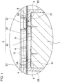
- battery module 10 To prevent potting resin 13 from permeating inside through the outlet formed in projecting electrode 11 of each battery, battery module 10, as shown in the enlarged principal part sectional views of FIGS. 1 and 2 , includes first double-sided tape 4 and second double-sided tape 5 stuck on both respective surfaces of each outer peripheral cover 21 and sealing label 6 that is stuck on a surface of each lead plate 3 so as to close connection recesses 32.
- First double-sided tape 4, second double-sided tape 5, and sealing label 6 are used to prevent potting resin 13 that has not been cured from permeating inside through the outlet formed in each projecting electrode 11 and thus are stuck on only a surface area adjacent to projecting electrodes 11 of batteries 1.
- a piece of first double-sided tape 4 has a ring shape and provides a tight fit between an outer peripheral part of battery 1, i.e., an outer peripheral part of the sealing plate that is outside projecting electrode 11, and outer peripheral cover 21 of battery holder 2.
- First double-sided tape 4 ensures that the outer peripheral part of battery 1 fits tightly over outer peripheral cover 21 of battery holder 2 without a gap to prevent potting resin 13 from permeating through any gap between the sealing plate and outer peripheral cover 21.
- First double-sided tape 4 shown in FIGS. 1 and 2 is shaped into a ring that has an inside diameter substantially equal to an inside diameter of electrode window 24 and an outside diameter substantially equal to or, more precisely, slightly smaller than the outside diameter of battery 1 to provide a tight fit between the sealing plate of battery 1 and outer peripheral cover 21.
- First double-sided tape 4 is larger than an outside diameter of projecting electrode 11 and is shaped such that a surface of projecting electrode 11 is fully exposed while the first double-sided tape is stuck on the sealing plate.
- First double-sided tape 4 is tape that includes adhesive layers on both sides, is disposed between the outer peripheral part of battery 1 and outer peripheral cover 21, and presses outer peripheral cover 21 to provide close adhesion.
- Apiece of second double-sided tape 5 provides a tight fit between outer peripheral cover 21 of battery holder 2 and planar part 31 of lead plate 3 and ensures that a surface of outer peripheral cover 21 fits tightly over planar part 31 of lead plate 3 to prevent potting resin 13 from permeating through any gap between outer peripheral cover 21 and lead plate 3.
- An external shape of second double-sided tape 5 is larger than an external shape of first double-sided tape 4. The second double-sided tape covering a large area is put into intimate contact with the surface of outer peripheral cover 21 to securely seal a joint between outer peripheral cover 21 and lead plate 3. Second double-sided tape 5 shown in FIG.
- second double-sided tape 5 has an external shape that is similar to an internal shape of filling room 23 so as to cover an area including opening edges of a plurality of electrode windows 24 opened in outer peripheral cover 21 of battery holder 2.
- the external shape of second double-sided tape 5 is made identical to an external shape of lead plate 3 such that a single piece of second double-sided tape 5 can cover overall lead plate 3.
- second double-sided tape 5 has through-holes 5A that are opened at places facing the plurality of electrode windows 24 opened in the bottom surface of filling room 23.
- Connection recesses 32 of lead plate 3 are configured to pass through through-holes 5A and be connected to projecting electrodes 11 exposed out of electrode windows 24.
- Second double-sided tape 5 is also tape that includes adhesive layers on both sides, is disposed between outer peripheral cover 21 and lead plate 3, and presses lead plate 3 to provide close adhesion.
- Sealing label 6 is tape that potting resin 13 is not allowed to pass through and that has an adhesive layer on one side. Sealing label 6 is put into intimate contact with planar part 31 of lead plate 3 so as to close the openings of connection recesses 32. Sealing label 6 is shaped such that sealing label 6 comes into intimate contact with planar part 31 adjacent to an entire periphery of each connection recess 32 and is put into intimate contact with planar part 31 to prevent potting resin 13 from flowing into connection recesses 32. Sealing label 6 in FIGS. 4 and 5 has an external shape that covers a series of a plurality of connection recesses 32 adjacent to each other so as to cover an area including the plurality of connection recesses 32 connected to projecting electrodes 11 and close the connection recesses.
- sealing label 6 shown in the drawings is a zigzag shape that enables the sealing label to close four connection recesses 34 arranged in a zigzag line at a time. Sealing label 6 is stuck on a surface of each lead plate 3 and is put into intimate contact with an entire area contiguous to the plurality of connection recesses 32 adjacent to each other to securely close the openings of connection recesses 32.
- Battery module 10 having the configuration described above is assembled through steps described below.
- a battery module of the present invention is optimally applicable to a battery module having a structure in which an end face of a battery adjacent to a discharge valve is sealed with a potting resin.
Landscapes
- Chemical & Material Sciences (AREA)
- Chemical Kinetics & Catalysis (AREA)
- Electrochemistry (AREA)
- General Chemical & Material Sciences (AREA)
- Battery Mounting, Suspending (AREA)
- Connection Of Batteries Or Terminals (AREA)
- Gas Exhaust Devices For Batteries (AREA)
Abstract
Description
- The present invention relates to a battery module in which a projecting electrode side of a battery is thermally coupled to a potting resin, and particularly to a battery module including a discharge valve disposed on a projecting electrode side of a battery.
- A battery module in which a projecting electrode side of a battery is thermally coupled to a potting resin has been developed (see PTL 1).
- A battery module having this structure allows adjacent batteries to be thermally coupled to each other through a potting resin and thus is characterized by being able to reduce unevenness in temperatures of the batteries arranged at fixed positions. Each of the batteries with an outlet of a discharge valve formed in a projecting electrode is required to prevent the potting resin from flowing inside through the outlet when an end of the battery is buried under the potting resin. This is because the potting resin that has flowed inside hinders proper operation of the discharge valve. To prevent the inflow of the resin, the inventors of the present invention developed, as shown in an enlarged cross-sectional view of
FIG. 7 , a structure in whichsealing label 106 is stuck on projectingelectrode 111 ofbattery 101 and an end of the battery is buried under a potting resin. A battery module in this drawing includes ring-shaped sealing label 106 that breaks by an exhaust gas and that is stuck on an end face of the battery adjacent to projectingelectrode 111. A center of sealinglabel 106 hasattachment hole 107 that is opened to expose a middle of projectingelectrode 111, and an outer peripheral part of the sealing label is stuck on an outer peripheral part ofsealing plate 112.Sealing label 106 is stuck on both an outer peripheral part of projectingelectrode 111 and the outer peripheral part ofsealing plate 112 and coversoutlet 113 formed in an upright part of projectingelectrode 111 to prevent inflow of the potting resin throughoutlet 113. - PTL 1: Unexamined Japanese Patent Publication No.
2008-251471 - However, the battery module shown in
FIG. 7 , because of difficulty in connectinglead plate 103 used to connect a battery to an adjacent battery in series or in parallel, has a disadvantage of not allowing stable and reliable connection oflead plate 103 to projectingelectrode 111. This is because ring-shaped sealing label 106 stuck on the outer peripheral part of projectingelectrode 111 narrows an exposed area of the projecting electrode.Lead plate 103, a metal sheet, is connected to exposedface 111A formed on a surface of projectingelectrode 111 by spot welding, laser welding, or ultrasonic welding while the lead plate is reliably in contact with the exposed face. However, while connectingpart 133 oflead plate 103 is not allowed to be reliably in contact with exposedface 111A on the surface of projectingelectrode 111, reliable and stable connection is not possible. In particular, spot welding has a characteristic of enabling reliable and stable connection oflead plate 103, and this method, as shown in an enlarged plan view ofFIG. 8 , involves pressing a pair of welding electrodes against twowelding points 137 formed on either side ofslit 136 to avoid reactive current and passing a current between the electrodes to weldlead plate 103. However, a failure of contact with anywelding point 137 hinders stable connection. A battery commonly called "18650" that is frequently used as a cylindrical lithium ion secondary battery in a variety of applications is formed into a circular cylinder that measures 18 mm in outside diameter and 650 mm in overall length. A smaller projecting electrode is disposed on an end face of the battery with an outside diameter of 18 mm, and a lead plate is connected to the projecting electrode. Thus, if a sealing label is stuck on an outer peripheral part of the electrode and an exposed area of the electrode gets even smaller, connecting the lead plate is very difficult and stable and reliable connection in particular is substantially difficult. This causes the battery module to have a lowered yield and causes the product to offer decreased stability. - The present invention has been accomplished to solve the above problem. It is an object of the present invention to provide a battery module that allows a lead plate to be stably and reliably connected to a projecting electrode while preventing inflow of a potting resin through an outlet formed in the projecting electrode.
- A battery module according to an aspect of the present invention includes a plurality of
batteries 1 each including an outlet of a discharge valve disposed in a projectingelectrode 11 on an end face of each of the plurality of batteries, abattery holder 2 arranging thebatteries 1 parallel to each other at fixed positions, alead plate 3 connected to the projectingelectrode 11 of each of thebatteries 1 that are arranged at the fixed positions by thebattery holder 2, the end face of each of thebatteries 1 being disposed on a same plane, and pottingresin 13 thermally coupled to thelead plate 3. The discharge valve is configured to open when an internal pressure of each of thebatteries 1 rises to a set pressure. Thebattery holder 2 includes an outerperipheral cover 21 having anelectrode window 24 to expose the projectingelectrode 11 and being disposed on a plane facing an outer peripheral edge of the projectingelectrode 11. Thelead plate 3 includes aplanar part 31 disposed over a surface of the outerperipheral cover 21 and aconnection recess 32 disposed in theplanar part 31. The connection recess is guided into theelectrode window 24 in thebattery holder 2 and protrudes toward the projectingelectrode 11 to connect aprotrusion face 33 to the projectingelectrode 11. In the battery module, a first double-sided tape 4 provides a tight fit between an outer peripheral part of each of thebatteries 1 and the outer peripheral cover of thebattery holder 2 to ensure that the outer peripheral part of each of thebattery 1 fits tightly over the outerperipheral cover 21. A second double-sided tape 5 provides a tight fit between the outerperipheral cover 21 of thebattery holder 2 and theplanar part 31 of thelead plate 3 to ensure that the outerperipheral cover 21 fits tightly over theplanar part 31 of thelead plate 3. Asealing label 6 is put into intimate contact with theplanar part 31 of thelead plate 3 to ensure that thesealing label 6 closes an opening of theconnection recess 32 of thelead plate 3. The first double-sided tape 4, the second double-sided tape 5, and thesealing label 6 constitute a structure that prevents the pottingresin 13 from flowing into the outlet disposed in the projectingelectrode 11 of each of the batteries. - The battery module described above is characterized by allowing the lead plate to be stably and reliably connected to the projecting electrode while preventing the potting resin from flowing inside through the outlet formed in the projecting electrode. This is because the battery module is able to prevent inflow of the potting resin through the outlet without a sealing label stuck on a surface of the projecting electrode. In the battery module, as shown in enlarged principal part sectional views of
FIGS. 1 and2 , thesealing label 6 is not stuck on the projectingelectrode 11 but is stuck on a surface of thelead plate 3 connected to the projectingelectrode 11. In addition to thesealing label 6, the battery module includes the first double-sided tape 4 and the second double-sided tape 5 stuck on both sides of the outerperipheral cover 21 of thebattery holder 2 to prevent thepotting resin 13 from flowing through any gap between an outer peripheral edge of each of thebatteries 1 and the outerperipheral cover 21 of thelead plate 3. - Thus, unlike the conventional battery module, the battery module described above is without the sealing label stuck on the projecting electrode and is able to prevent the potting resin from flowing inside through the outlet formed in the projecting electrode by means of the sealing label and the double-sided tape. In particular, the battery module described above eliminates the need for precisely sticking a sealing label on an outer peripheral edge of a small projecting electrode. This makes a process of sticking a sealing label simple and effortless and enables efficient mass production of the battery module. The battery module allows the lead plate to be connected to a fully exposed surface of the projecting electrode and hence contributes to reliable and stable connection of the lead plate. Further, the lead plate is stuck to the battery holder through the double-sided tape, and the battery holder is stuck to the end face of the electrode of the battery through the double-sided tape. This configuration allows the lead plate to be connected to the projecting electrode while the lead plate is temporarily fixed through the double-sided tape to avoid misalignment. This also allows the lead plate to be connected to the projecting electrode with increased reliability and stability.
- In a battery module according to another aspect of the present invention, the
batteries 1 may be cylindrical batteries. - In a battery module according to another aspect of the present invention, the
sealing label 6 may have an external shape that covers a series of a plurality of connection recesses 32 being adjacent to each other and being connected to a plurality of projectingelectrodes 11. - The configuration described above enables a single sheet of the sealing label to close a series of the plurality of the connection recesses adjacent to each other. An entire area of the sealing label can be widened to cover an area including the plurality of the connection recesses and close the connection recesses, and an adhesive layer can also be disposed on an area between the connection recesses adjacent to each other. This enables the sealing label to display increased adhesive strength for the lead plate and reliably close the connection recesses. A single sheet of the sealing label closes the plurality of the connection recesses. This helps to reduce time required for manufacturing as well as manufacturing costs.
- In a battery module according to another aspect of the present invention, first double-
sided tape 4 may have a ring shape and may have an inside diameter substantially equal to an inside diameter of theelectrode window 24 and an outside diameter substantially equal to an outside diameter of thebattery 1. - The configuration described above enables the first double-sided tape with a widened area to be put into intimate contact with the outer peripheral part of each of the batteries and the outer peripheral cover of the battery holder and provide reliable sealing. This configuration also enables an entire surface of the projecting electrode of the battery to be reliably exposed out of the electrode window.
- In a battery module according to another aspect of the present invention, the second double-
sided tape 5 may have an external shape substantially identical to an external shape of thelead plate 3, cover an area including a plurality of theelectrode windows 24 opened in thebattery holder 2, and include through-holes 5A that are opened at places facing therespective electrode windows 24 so as to be similar in outline to theelectrode windows 24. The plurality of connection recesses 32 are disposed in the respective through-holes 5A. - The configuration described above enables the second double-sided tape with a widened area to be put into intimate contact with the planar part of the lead plate and opening edges of the plurality of the electrode windows opened in the outer peripheral cover and provide reliable sealing. This configuration also enables the connection recesses that are disposed in the through-holes opened in the second double-sided tape to be reliably put into contact with the projecting electrodes exposed out of the respective electrode windows. Further, a single sheet of the second double-sided tape is put into intimate contact with the opening edges of the plurality of the electrode windows and the planar part of the lead plate. This helps to reduce time required for manufacturing as well as manufacturing costs.
-
-
FIG. 1 is an enlarged vertical longitudinal sectional view of a principal part of a battery module according to an exemplary embodiment of the present invention, viewed along arrows I, I inFIG. 4 . -
FIG. 2 is an enlarged vertical transverse sectional view of a principal part of a battery module according to an exemplary embodiment of the present invention, viewed along arrows II, II inFIG. 4 . -
FIG. 3 is a perspective view of a battery module according to an exemplary embodiment of the present invention. -
FIG. 4 is a plan view of the battery module shown inFIG. 3 . -
FIG. 5 is an exploded perspective view of the battery module shown inFIG. 3 . -
FIG. 6 is a sectional view of the battery module shown inFIG. 3 , viewed along arrows VI, VI. -
FIG. 7 is an enlarged sectional view illustrating a principal part of a coupling structure of a battery and a sealing label in a conventional battery module. -
FIG. 8 is an enlarged plan view illustrating a connection structure of the battery and a lead plate shown inFIG. 7 . - Hereinafter, an exemplary embodiment of the present invention will be described with reference to the drawings. It is to be noted, however, that the exemplary embodiment described below is an illustration embodying a technical idea of the present invention, and the present invention is not specifically limited to the following exemplary embodiment. The components recited in the claims are not limited to the components described in the exemplary embodiment. In particular, it is not intended to limit the scope of the present invention to sizes, materials, shapes, relative arrangement, and the like of the components, which are described in the exemplary embodiment, unless otherwise specified. The sizes and the like are mere explanation examples. The sizes, the relative positions, and others of the members may be illustrated exaggeratedly in the drawings for clear explanation. Furthermore, in the following description, the same names or the same reference marks denote the same components or same type components, and detailed description is appropriately omitted. A single member may be configured to serve as a plurality of elements of the present invention. On the other hand, a function of a single element of the present invention may be achieved by a plurality of members. Contents described in some examples or in the exemplary embodiment can be used, for example, in other examples or exemplary embodiments. A vertical direction described in the specification is specified in the drawings.
-
Battery module 10 shown in a perspective view ofFIG. 3 and a plan view ofFIG. 4 , includes, as shown in an exploded perspective view ofFIG. 5 , a plurality ofbatteries 1,battery holder 2 to arrange the plurality ofbatteries 1 parallel to one another at fixed positions,lead plates 3 to connect electrodes ofbatteries 1 arranged on same planes, and pottingresin 13 thermally coupled to leadplates 3. Inbattery module 10, the plurality ofbatteries 1 are arranged at fixed positions bybattery holder 2,lead plates 3 are connected to both ends ofbatteries 1, and as shown in a vertical sectional view ofFIG. 6 , pieces of pottingresin 13 are disposed outsidelead plates 3 and thermally coupled to leadplates 3 and the ends ofbatteries 1. -
Battery module 10 further includes first double-sided tape 4, second double-sided tape 5, and sealinglabels 6 to prevent liquid orpasty potting resin 13 from permeating inside through an outlet of a discharge valve formed in projectingelectrode 11 of eachbattery 1 while being filled with pottingresin 13. -
Battery 1 has positive and negative electrodes on both ends. One of the electrodes constitutes projectingelectrode 11 formed on a sealing plate and the other end isplane electrode 12 formed on a bottom of an exterior can.Battery 1 is a cylindrical lithium ion secondary battery provided with an outlet formed in projectingelectrode 11. The lithium ion secondary battery has a large capacity relative to its size and weight and enablesbattery module 10 to have an increased overall capacity. However,batteries 1 for the battery module of the present invention are not limited to lithium ion secondary batteries.Batteries 1 may be, for example, nickel metal hydride batteries, nickelcadmium batteries, or other rechargeable batteries. Inbattery module 10 shown in the drawings,batteries 1 are cylindrical batteries. The batteries may, however, be prismatic batteries.Lead plates 3 are welded to projectingelectrodes 11 on both ends ofbatteries 1 by spot welding or another technique to connectadjacent batteries 1 in series or in parallel. -
Battery 1 has a discharge valve (not shown) inside the sealing plate. The discharge valve opens when an internal pressure ofbattery 1 gets higher than a set pressure and thereby prevents a case of the battery from rupturing. The opened discharge valve discharges an exhaust gas outside to prevent the internal pressure from rising. The sealing plate has an outlet on a periphery of projectingelectrode 11 to discharge the exhaust gas from the opened discharge valve. When the internal pressure ofbattery 1 gets higher than the set pressure,battery 1 lets the discharge valve open to discharge an exhaust gas outside through the outlet formed on the periphery of projectingelectrode 11 and prevent a rupture caused by a rise in the internal pressure. -
Battery holder 2 arrangesbatteries 1 parallel to one another at fixed positions such that end faces of the batteries where projectingelectrodes 11 andplane electrodes 12 exist are arranged on respective same planes.Battery holder 2 is made by molding an insulating material such as a plastic.Battery holder 2 shown inFIGS. 3 and4 includes a pair of outer peripheral covers 21 to cover both end surfaces ofbatteries 1, both end faces of which are arranged on the respective same planes, andinsertion parts 22 thatbatteries 1 are inserted into and are thereby arranged at fixed positions. Each of the outer peripheral covers and the corresponding insertion parts are integrally molded.Battery holder 2 arrangesbatteries 1 at fixed positions such that all the batteries are parallel to one another.Lead plates 3 are welded to and connected to both ends ofbatteries 1. To make sure thatplanar lead plates 3 are connected to the end faces ofbatteries 1,battery holder 2 allowsbatteries 1 to be inserted intoinsertion parts 22 and be arranged at specified positions such that both ends of the batteries are substantially flush with respective same level surfaces. -
Battery holder 2 shown in the exploded perspective view ofFIG. 5 is divided into two members on both sides of batteries 1 (divisible into two of upper and lower members inFIG. 5 ) and is molded from a plastic. Further,battery holder 2 shown inFIGS. 3 and4 has fillingroom 23 in a surface of each outerperipheral cover 21 coveringbatteries 1. The filling room is filled with pottingresin 13. InFIG. 5 , fillingroom 23 is formed in an upper surface of the member ofbattery holder 2 disposed on an upper side, and fillingroom 23 is formed in a lower surface of the member ofbattery holder 2 disposed on a lower side. -
Battery holder 2 hasinsertion parts 22, whichbatteries 1 are inserted into and are arranged at fixed positions. Inbattery module 10 shown in the drawings,batteries 1 are cylindrical batteries, and henceinsertion parts 22 are each cylindrical. An inside diameter ofcylindrical insertion part 22 is slightly larger than an outside diameter ofbattery 1 to enable smooth insertion ofbattery 1. While the battery is being inserted into the insertion part, a tiny gap is left between a surface ofbattery 1 and an inner surface ofinsertion part 22.Battery holder 2 may haveinsertion parts 22 that are formed inside cylindrical shapes molded from a plastic or may haveinsertion parts 22 by molding a plastic into a block and making cylindrical through-holes inside the block.Battery holder 2 including the insertion parts molded from a plastic into cylindrical shapes arrangesbatteries 1 at fixed positions by allowing the batteries to be inserted intocylindrical insertion parts 22. Thisbattery holder 2 is able to effectively prevent thermal runaway becauseadjacent batteries 1 are inserted into separately moldedinsertion parts 22.Battery holder 2 that allowsbatteries 1 to be inserted into through-hole insertion parts 22 has a large heat capacity and is thus able to absorb heat frombattery 1 to prevent a rise in temperature ofbattery 1 and make a temperature difference betweenadjacent batteries 1 smaller. -
Battery holder 2 has outer peripheral covers 21 on both ends of pairs ofinsertion parts 22. The outer peripheral covers have electrodewindows 24 through which the ends ofbatteries 1 are exposed and connected to leadplates 3.Electrode windows 24 each expose the end face ofbattery 1 inserted intoinsertion part 22 to an outside, i.e., a bottom of fillingroom 23, out ofinsertion part 22.Lead plates 3 are welded to the electrodes on both ends of eachbattery 1 exposed to fillingrooms 23 throughrespective electrode windows 24.Lead plates 3 welded to the electrodes are disposed at the bottoms ofrespective filling rooms 23. - As shown in the sectional view of
FIG. 6 , to make sure that fillingrooms 23 are filled withpasty potting resin 13 that has not been cured,peripheral wall 25 is formed along an outer periphery of a zone filled with pottingresin 13, and the zone inside eachperipheral wall 25 constitutes fillingroom 23. A thickness of pottingresin 13 loaded intofilling room 23 can be controlled by a height ofperipheral wall 25. Highperipheral wall 25 means thatdeep filling room 23 can be filled with a large amount of pottingresin 13. A depth of fillingroom 23 ranges, for example, from about 1 mm to 10 mm so that pottingresin 13 loaded into the filling room has a thickness to facilitate heat conduction and decrease temperature difference betweenadjacent batteries 1. -
Lead plates 3 are metal sheets that are connected to the ends ofadjacent batteries 1 to connectbatteries 1 in series or in parallel.Lead plates 3 are connected to projectingelectrodes 11 andplane electrodes 12, positive and negative electrodes ofbatteries 1, to connectbatteries 1 in series or in parallel. Leadplate 3 includesplanar part 31 and connection recesses 32 formed in the planar part.Planar part 31 is disposed over a bottom surface of fillingroom 23 inbattery holder 2, i.e., an outer surface of outerperipheral cover 21 included inbattery holder 2, whereas connection recesses 32 are guided intoelectrode windows 24 in outerperipheral cover 21 to let protrusion faces 33 protruding toward the electrodes ofbatteries 1 be connected tobatteries 1.Planar part 31 is present around eachconnection recess 32, andlead plate 3 is shaped such that openings of connection recesses 32 are closed withsealing label 6 bonded toplanar part 31. - Lead
plate 3 in which connection recesses 32 are formed inplanar part 31 is made by cutting a planar metal sheet and bending the cut metal sheet. Since protrusion faces 33 are connected to projectingelectrodes 11 andplane electrodes 12 formed on the end faces ofbatteries 1, connection recesses 32 are disposed at places facing projectingelectrodes 11 andplane electrodes 12 ofbatteries 1 that are disposed at fixed positions bybattery holder 2. Leadplate 3 has separation slits 34 that are each formed along an outer periphery ofconnection recess 32. Separation slit 34 is formed partly along the outer periphery ofconnection recess 32, and a part of the outer periphery where no separation slit 34 is present constitutes linkingpart 35. Protrusion faces 33 are linked toplanar part 31 through respective linkingparts 35. Linkingpart 35 is bend and shaped such that protrusion face 33 ofconnection recess 32 is inserted intoelectrode window 24 and is put into contact with and connected to the electrode ofbattery 1. Leadplate 3 having separation slit 34 betweenprotrusion face 33 andplanar part 31puts connection recess 32 at a deep level, or in other words, letsprotrusion face 33 protrude fromplanar part 31 to a high degree and thereby enables the protrusion face to be connected to the electrode ofbattery 1. However, in a battery module of the present invention, a lead plate does not necessarily have a separation slit on an outer peripheral edge of a connection recess and may let a protrusion face protrude from a planar part without a separation slit to enable the protrusion face to be connected to an electrode of a battery. - Protrusion face 33 connected to the electrode of
battery 1 includes welding slit 36 extending to a side away from linkingpart 35 andwelding points 37 disposed on both sides of welding slit 36. The welding points are designed to be pressed by positive and negative welding electrodes and be welded to the electrode of the battery. In the drawings,lead plate 3 has twowelding points 37 on either side of every welding slit 36 and a welding protrusion on eachwelding point 37. This structure enables the lead plate to be reliably welded to the electrode ofbattery 1. Leadplate 3 is shaped such that, when the lead plate is set in fillingroom 23 inbattery holder 2, connection recesses 32 are guided intoelectrode windows 24 and the welding protrusions are put into contact with projectingelectrodes 11 andplane electrodes 12 ofbatteries 1. However, even if the welding protrusions are not put into contact with the electrodes ofbatteries 1 whenlead plate 3 is set in fillingroom 23, the welding protrusions can be pressed by positive and negative welding electrodes so as to be put into contact with and be connected to the electrodes ofbatteries 1. This configuration allows protrusion faces 33 to be reliably and stably connected to the electrodes ofbatteries 1 by spot welding. The present invention, however, is not intended to limit a way of connecting protrusion faces 33 to the electrodes ofbatteries 1 to spot welding. This is because the protrusion faces can be connected to the electrodes of the batteries by laser welding or ultrasonic welding. A process of connecting protrusion faces 33 to the electrodes ofbatteries 1 by laser welding involves pressing protrusion faces 33 to put the protrusion faces into contact with the electrodes ofbatteries 1 while the welding points are irradiated with laser beams. - To prevent
potting resin 13 from permeating inside through the outlet formed in projectingelectrode 11 of each battery,battery module 10, as shown in the enlarged principal part sectional views ofFIGS. 1 and2 , includes first double-sided tape 4 and second double-sided tape 5 stuck on both respective surfaces of each outerperipheral cover 21 andsealing label 6 that is stuck on a surface of eachlead plate 3 so as to close connection recesses 32. First double-sided tape 4, second double-sided tape 5, and sealinglabel 6 are used to preventpotting resin 13 that has not been cured from permeating inside through the outlet formed in each projectingelectrode 11 and thus are stuck on only a surface area adjacent to projectingelectrodes 11 ofbatteries 1. - A piece of first double-
sided tape 4 has a ring shape and provides a tight fit between an outer peripheral part ofbattery 1, i.e., an outer peripheral part of the sealing plate that is outside projectingelectrode 11, and outerperipheral cover 21 ofbattery holder 2. First double-sided tape 4 ensures that the outer peripheral part ofbattery 1 fits tightly over outerperipheral cover 21 ofbattery holder 2 without a gap to preventpotting resin 13 from permeating through any gap between the sealing plate and outerperipheral cover 21. First double-sided tape 4 shown inFIGS. 1 and2 is shaped into a ring that has an inside diameter substantially equal to an inside diameter ofelectrode window 24 and an outside diameter substantially equal to or, more precisely, slightly smaller than the outside diameter ofbattery 1 to provide a tight fit between the sealing plate ofbattery 1 and outerperipheral cover 21. First double-sided tape 4 is larger than an outside diameter of projectingelectrode 11 and is shaped such that a surface of projectingelectrode 11 is fully exposed while the first double-sided tape is stuck on the sealing plate. First double-sided tape 4 is tape that includes adhesive layers on both sides, is disposed between the outer peripheral part ofbattery 1 and outerperipheral cover 21, and presses outerperipheral cover 21 to provide close adhesion. - Apiece of second double-
sided tape 5 provides a tight fit between outerperipheral cover 21 ofbattery holder 2 andplanar part 31 oflead plate 3 and ensures that a surface of outerperipheral cover 21 fits tightly overplanar part 31 oflead plate 3 to preventpotting resin 13 from permeating through any gap between outerperipheral cover 21 andlead plate 3. An external shape of second double-sided tape 5 is larger than an external shape of first double-sided tape 4. The second double-sided tape covering a large area is put into intimate contact with the surface of outerperipheral cover 21 to securely seal a joint between outerperipheral cover 21 andlead plate 3. Second double-sided tape 5 shown inFIG. 5 has an external shape that is similar to an internal shape of fillingroom 23 so as to cover an area including opening edges of a plurality ofelectrode windows 24 opened in outerperipheral cover 21 ofbattery holder 2. In other words, the external shape of second double-sided tape 5 is made identical to an external shape oflead plate 3 such that a single piece of second double-sided tape 5 can coveroverall lead plate 3. Further, second double-sided tape 5 has through-holes 5A that are opened at places facing the plurality ofelectrode windows 24 opened in the bottom surface of fillingroom 23. Connection recesses 32 oflead plate 3 are configured to pass through through-holes 5A and be connected to projectingelectrodes 11 exposed out ofelectrode windows 24. An inside diameter of each through-hole 5A opened in second double-sided tape 5 is substantially equal to or, more precisely, slightly larger than the inside diameter ofelectrode window 24 and is larger than the outside diameter of projectingelectrode 11. This is intended to make sure that the exposed surface of projectingelectrode 11 is not narrowed when the second double-sided tape is stuck on the outer peripheral cover. Second double-sided tape 5 is also tape that includes adhesive layers on both sides, is disposed between outerperipheral cover 21 andlead plate 3, and presseslead plate 3 to provide close adhesion. -
Sealing label 6 is tape that pottingresin 13 is not allowed to pass through and that has an adhesive layer on one side.Sealing label 6 is put into intimate contact withplanar part 31 oflead plate 3 so as to close the openings of connection recesses 32.Sealing label 6 is shaped such thatsealing label 6 comes into intimate contact withplanar part 31 adjacent to an entire periphery of eachconnection recess 32 and is put into intimate contact withplanar part 31 to preventpotting resin 13 from flowing into connection recesses 32.Sealing label 6 inFIGS. 4 and5 has an external shape that covers a series of a plurality of connection recesses 32 adjacent to each other so as to cover an area including the plurality of connection recesses 32 connected to projectingelectrodes 11 and close the connection recesses. Specifically, the external shape of sealinglabel 6 shown in the drawings is a zigzag shape that enables the sealing label to close fourconnection recesses 34 arranged in a zigzag line at a time.Sealing label 6 is stuck on a surface of eachlead plate 3 and is put into intimate contact with an entire area contiguous to the plurality of connection recesses 32 adjacent to each other to securely close the openings of connection recesses 32. -
Battery module 10 having the configuration described above is assembled through steps described below. - (1) First double-
sided tape 4 is stuck onto the outer peripheral part of the sealing plate of eachbattery 1. - (2)
Batteries 1 on which first double-sided tape 4 is stuck are inserted intoinsertion parts 22 of the divided members ofbattery holder 2 and the members ofbattery holder 2 are joined together to put first double-sided tape 4 into intimate contact with inner surfaces of outer peripheral covers 21. In this state, the sealing plates are fit tightly over the inner surfaces of outer peripheral covers 21 to close any gap between the sealing plates and outer peripheral covers 21. - (3) Second double-
sided tape 5 is stuck onto a top surface of each outerperipheral cover 21 ofbattery holder 2 that isoutside electrode windows 24, or second double-sided tape 5 is stuck onto an inner surface of eachlead plate 3 that is contiguous to the outer peripheries of connection recesses 32. - (4)
Lead plate 3 is guided into each fillingroom 23 inbattery holder 2 and second double-sided tape 5 is put into intimate contact with both the inner surfaces oflead plates 3 and the surfaces of outer peripheral covers 21 to close any gap betweenlead plates 3 and each outerperipheral cover 21. In this state, connection recesses 32 oflead plates 3 are guided intoelectrode windows 24 in outer peripheral covers 21 to put protrusion faces 33 into contact with the electrodes ofbatteries 1. - (5) Protrusion faces 33 formed in connection recesses 32 of each
lead plate 3 are connected to the electrodes ofbatteries 1 by spot welding. - (6)
Sealing label 6 is stuck onto the surface of eachlead plate 3 to close the openings of connection recesses 32 formed inlead plate 3 and preventpotting resin 13 from passing through the openings. - (7) Liquid or
pasty potting resin 13 that has not been cured is injected into each fillingroom 23 and is cured. Curedpotting resin 13 is thermally coupled tobatteries 1 throughlead plates 3 to reduce a rise in the temperature ofbatteries 1. - A battery module of the present invention is optimally applicable to a battery module having a structure in which an end face of a battery adjacent to a discharge valve is sealed with a potting resin.
-
- 1:
- battery
- 2:
- battery holder
- 3:
- lead plate
- 4:
- first double-sided tape
- 5:
- second double-sided tape
- 5A:
- through-hole
- 6:
- sealing label
- 10:
- battery module
- 11:
- projecting electrode
- 12:
- plane electrode
- 13:
- potting resin
- 21:
- outer peripheral cover
- 22:
- insertion part
- 23:
- filling room
- 24:
- electrode window
- 25:
- peripheral wall
- 31:
- planar part
- 32:
- connection recess
- 33:
- protrusion face
- 34:
- separation slit
- 35:
- linking part
- 36:
- welding slit
- 37:
- welding point
- 101:
- battery
- 103:
- lead plate
- 106:
- sealing label
- 107:
- attachment hole
- 111:
- projecting electrode
- 111A:
- exposed face
- 112:
- sealing plate
- 113:
- outlet
- 133:
- connecting part
- 136:
- slit
- 137:
- welding point
Claims (5)
- A battery module comprising:a plurality of batteries each including an outlet of a discharge valve disposed in a projecting electrode on an end face of each of the plurality of batteries, the discharge valve being configured to open when an internal pressure of each of the plurality of batteries rises to a set pressure;a battery holder arranging the plurality of batteries parallel to each other at fixed positions;a lead plate connected to the projecting electrode of each of the plurality of batteries that are arranged at the fixed positions by the battery holder, the end face of each of the plurality of batteries being disposed on a same plane; anda potting resin thermally coupled to the lead plate,wherein the battery holder includes an outer peripheral cover having an electrode window to expose the projecting electrode and being disposed on a plane facing an outer peripheral edge of the projecting electrode,the lead plate includes:a planar part disposed over a surface of the outer peripheral cover; anda connection recess disposed in the planar part, the connection recess being guided into the electrode window in the battery holder and protruding toward the projecting electrode to connect a protrusion face of the connection recess to the projecting electrode,a first double-sided tape provides a tight fit between an outer peripheral part of each of the plurality of batteries and the outer peripheral cover of the battery holder to ensure that the outer peripheral part of each of the plurality of batteries fits tightly over the outer peripheral cover,a second double-sided tape provides a tight fit between the outer peripheral cover of the battery holder and the planar part of the lead plate to ensure that the outer peripheral cover fits tightly over the planar part of the lead plate,a sealing label is put into intimate contact with the planar part of the lead plate to ensure that the sealing label closes an opening of the connection recess of the lead plate, andthe first double-sided tape, the second double-sided tape, and the sealing label constitute a structure that prevents the potting resin from flowing into the outlet disposed in the projecting electrode.
- The battery module according to claim 1, wherein each of the plurality of batteries is a cylindrical battery.
- The battery module according to claim 1 or 2, wherein the sealing label has an external shape that covers a series of a plurality of the connection recesses being adjacent to each other and being connected to a plurality of the projecting electrodes.
- The battery module according to any one of claims 1 to 3, wherein the first double-sided tape has a ring shape and has an inside diameter substantially equal to an inside diameter of the electrode window and an outside diameter substantially equal to an outside diameter of each of the plurality of batteries.
- The battery module according to any one of claims 1 to 4, wherein
the second double-sided tape has an external shape substantially identical to an external shape of the lead plate, covers an area including a plurality of the electrode windows opened in the battery holder, and includes through-holes that are opened at places facing the respective electrode windows so as to be similar in outline to the plurality of electrode windows, and
the plurality of the connection recesses are disposed in the respective through-holes.
Applications Claiming Priority (2)
| Application Number | Priority Date | Filing Date | Title |
|---|---|---|---|
| JP2017144774 | 2017-07-26 | ||
| PCT/JP2018/027415 WO2019021980A1 (en) | 2017-07-26 | 2018-07-23 | Battery module |
Publications (3)
| Publication Number | Publication Date |
|---|---|
| EP3660947A1 true EP3660947A1 (en) | 2020-06-03 |
| EP3660947A4 EP3660947A4 (en) | 2020-07-08 |
| EP3660947B1 EP3660947B1 (en) | 2021-09-01 |
Family
ID=65040263
Family Applications (1)
| Application Number | Title | Priority Date | Filing Date |
|---|---|---|---|
| EP18839174.2A Active EP3660947B1 (en) | 2017-07-26 | 2018-07-23 | Battery module |
Country Status (6)
| Country | Link |
|---|---|
| US (1) | US11276906B2 (en) |
| EP (1) | EP3660947B1 (en) |
| JP (1) | JP7160808B2 (en) |
| AU (1) | AU2018307012B2 (en) |
| NZ (1) | NZ761684A (en) |
| WO (1) | WO2019021980A1 (en) |
Cited By (1)
| Publication number | Priority date | Publication date | Assignee | Title |
|---|---|---|---|---|
| EP4550561A4 (en) * | 2022-06-30 | 2025-10-22 | Panasonic Energy Co Ltd | BATTERY PACK |
Families Citing this family (24)
| Publication number | Priority date | Publication date | Assignee | Title |
|---|---|---|---|---|
| WO2018022964A1 (en) | 2016-07-29 | 2018-02-01 | Crynamt Management Llc | Battery packs having structural members for improving thermal management |
| US11757149B1 (en) | 2016-09-20 | 2023-09-12 | Apple Inc. | Battery liquid quench system and methods of manufacture thereof |
| US10923788B1 (en) | 2016-11-30 | 2021-02-16 | Apple Inc. | Directed quench systems and components |
| US11870092B1 (en) | 2017-02-01 | 2024-01-09 | Apple Inc. | On-board vent gas abatement |
| US11469471B1 (en) | 2018-02-02 | 2022-10-11 | Apple Inc. | Battery pack heat dispensing systems |
| KR102828348B1 (en) * | 2019-09-09 | 2025-07-03 | 삼성에스디아이 주식회사 | Battery pack |
| KR102828349B1 (en) | 2019-09-09 | 2025-07-03 | 삼성에스디아이 주식회사 | Battery pack |
| KR102572650B1 (en) * | 2019-11-29 | 2023-08-31 | 삼성에스디아이 주식회사 | Battery pack |
| KR102561801B1 (en) | 2019-11-29 | 2023-07-31 | 삼성에스디아이 주식회사 | Battery pack |
| KR20210067647A (en) | 2019-11-29 | 2021-06-08 | 삼성에스디아이 주식회사 | Battery pack |
| KR102574517B1 (en) | 2019-11-29 | 2023-09-04 | 삼성에스디아이 주식회사 | Battery pack |
| KR102533159B1 (en) | 2019-11-29 | 2023-05-17 | 삼성에스디아이 주식회사 | Battery pack |
| KR102501080B1 (en) | 2019-11-29 | 2023-02-17 | 삼성에스디아이 주식회사 | Battery pack |
| US11764431B2 (en) | 2020-10-22 | 2023-09-19 | Apple Inc. | Battery pack structures and systems |
| JP7633288B2 (en) * | 2021-02-09 | 2025-02-19 | エルジー エナジー ソリューション リミテッド | Battery module, battery pack including same, and automobile |
| EP4322312A4 (en) * | 2021-05-06 | 2025-03-05 | LG Energy Solution, Ltd. | BUSBAR ARRANGEMENT, BATTERY PACK THEREFORE AND AUTOMOTIVE |
| KR102598325B1 (en) * | 2021-07-13 | 2023-11-02 | (주)코미트 | Series-parallel lithium-ion battery packs with a surface-mounted electrode bonding plate with circular nickel terminals |
| US12009655B2 (en) | 2021-09-15 | 2024-06-11 | Apple Inc. | Switchable pyro fuse |
| JP7652914B2 (en) * | 2021-12-16 | 2025-03-27 | エルジー エナジー ソリューション リミテッド | Battery module with improved safety |
| CN115621648B (en) * | 2022-11-07 | 2024-08-27 | 哈尔滨理工大学 | Double-salient-pole battery connection structure and battery module |
| KR20240155809A (en) * | 2023-04-20 | 2024-10-29 | 주식회사 엘지에너지솔루션 | Battery module and Battery pack comprising the same |
| WO2024219873A1 (en) * | 2023-04-20 | 2024-10-24 | 주식회사 엘지에너지솔루션 | Battery module and battery pack comprising same |
| DE102023111889A1 (en) * | 2023-05-08 | 2024-11-14 | Bayerische Motoren Werke Aktiengesellschaft | Electrical energy storage device for a motor vehicle, in particular for a motor vehicle, and motor vehicle |
| US20260112751A1 (en) * | 2024-10-17 | 2026-04-23 | Toyota Jidosha Kabushiki Kaisha | Power storage device, and manufacturing method and inspection method thereof |
Family Cites Families (7)
| Publication number | Priority date | Publication date | Assignee | Title |
|---|---|---|---|---|
| JP4601432B2 (en) | 2005-01-12 | 2010-12-22 | 三洋電機株式会社 | Pack battery |
| JP5173227B2 (en) * | 2007-03-30 | 2013-04-03 | 三洋電機株式会社 | Pack battery |
| JP2012054121A (en) * | 2010-09-02 | 2012-03-15 | Sanyo Electric Co Ltd | Battery pack |
| JP5341156B2 (en) | 2011-09-06 | 2013-11-13 | 三洋電機株式会社 | Power supply |
| WO2014184993A1 (en) * | 2013-05-15 | 2014-11-20 | 三洋電機株式会社 | Battery pack and battery pack manufacturing method |
| JP5831608B2 (en) * | 2014-08-29 | 2015-12-09 | ソニー株式会社 | Battery unit |
| JP2018106796A (en) | 2015-05-07 | 2018-07-05 | 三洋電機株式会社 | Battery pack and manufacturing method of battery pack |
-
2018
- 2018-07-23 EP EP18839174.2A patent/EP3660947B1/en active Active
- 2018-07-23 NZ NZ761684A patent/NZ761684A/en unknown
- 2018-07-23 AU AU2018307012A patent/AU2018307012B2/en active Active
- 2018-07-23 US US16/633,019 patent/US11276906B2/en active Active
- 2018-07-23 JP JP2019532579A patent/JP7160808B2/en active Active
- 2018-07-23 WO PCT/JP2018/027415 patent/WO2019021980A1/en not_active Ceased
Cited By (1)
| Publication number | Priority date | Publication date | Assignee | Title |
|---|---|---|---|---|
| EP4550561A4 (en) * | 2022-06-30 | 2025-10-22 | Panasonic Energy Co Ltd | BATTERY PACK |
Also Published As
| Publication number | Publication date |
|---|---|
| EP3660947A4 (en) | 2020-07-08 |
| EP3660947B1 (en) | 2021-09-01 |
| JPWO2019021980A1 (en) | 2020-05-28 |
| US20200220147A1 (en) | 2020-07-09 |
| US11276906B2 (en) | 2022-03-15 |
| AU2018307012A1 (en) | 2020-02-27 |
| JP7160808B2 (en) | 2022-10-25 |
| AU2018307012B2 (en) | 2024-02-22 |
| WO2019021980A1 (en) | 2019-01-31 |
| NZ761684A (en) | 2026-01-30 |
Similar Documents
| Publication | Publication Date | Title |
|---|---|---|
| EP3660947B1 (en) | Battery module | |
| CN101048890B (en) | locking type battery pack | |
| EP1744384B1 (en) | Laminate type secondary battery and battery pack thereof | |
| CN108389983B (en) | Multifunctional ion bag-shaped battery unit frame | |
| RU2355070C1 (en) | Very thin accumulator power supply | |
| EP1501141B1 (en) | Separator for fuel cell | |
| CN101540381A (en) | Cap assembly and secondary battery using the same | |
| EP1422770B1 (en) | Prismatic sealed battery | |
| CN106611864B (en) | Electrolyte membrane-electrode structure with resin frame for fuel cell | |
| KR20200132294A (en) | Elastomer cell frame for fuel cell and Manufacturing method thereof and Fuel cell stack comprising thereof | |
| EP3555935B1 (en) | A battery module casing, a battery module and a battery | |
| US9029007B2 (en) | Rechargeable battery including first and second metallic plates coupled together and a cap assembly including an insulator | |
| JP7067300B2 (en) | Battery module and battery module manufacturing method | |
| CN120883433A (en) | Simplify the assembly of the burst membrane by using reinforcing components. | |
| KR102348074B1 (en) | Pouch sealing apparatus and method of manufacturing secondary battery | |
| KR101142682B1 (en) | Battery pack | |
| CN121507254A (en) | Battery cover and battery | |
| KR20200077304A (en) | Pouch-type Battery Case Comprising Asymmetrical Concave Part | |
| JP2013251123A (en) | Square secondary battery | |
| JP7103033B2 (en) | Power storage module and manufacturing method of power storage module | |
| CN114824412A (en) | Secondary battery and battery pack | |
| JP4172350B2 (en) | Fuel cell separator | |
| EP4625634A1 (en) | End cap assembly, battery apparatus, and power consumption device | |
| CN223193922U (en) | Battery case and battery device | |
| JP7764949B2 (en) | Battery pack |
Legal Events
| Date | Code | Title | Description |
|---|---|---|---|
| STAA | Information on the status of an ep patent application or granted ep patent |
Free format text: STATUS: THE INTERNATIONAL PUBLICATION HAS BEEN MADE |
|
| PUAI | Public reference made under article 153(3) epc to a published international application that has entered the european phase |
Free format text: ORIGINAL CODE: 0009012 |
|
| STAA | Information on the status of an ep patent application or granted ep patent |
Free format text: STATUS: REQUEST FOR EXAMINATION WAS MADE |
|
| 17P | Request for examination filed |
Effective date: 20200213 |
|
| AK | Designated contracting states |
Kind code of ref document: A1 Designated state(s): AL AT BE BG CH CY CZ DE DK EE ES FI FR GB GR HR HU IE IS IT LI LT LU LV MC MK MT NL NO PL PT RO RS SE SI SK SM TR |
|
| AX | Request for extension of the european patent |
Extension state: BA ME |
|
| A4 | Supplementary search report drawn up and despatched |
Effective date: 20200605 |
|
| RIC1 | Information provided on ipc code assigned before grant |
Ipc: H01M 2/20 20060101ALI20200529BHEP Ipc: H01M 2/34 20060101ALI20200529BHEP Ipc: H01M 2/22 20060101ALI20200529BHEP Ipc: H01M 2/12 20060101ALI20200529BHEP Ipc: H01M 2/10 20060101AFI20200529BHEP |
|
| DAV | Request for validation of the european patent (deleted) | ||
| DAX | Request for extension of the european patent (deleted) | ||
| REG | Reference to a national code |
Ref country code: DE Ref legal event code: R079 Ref document number: 602018023060 Country of ref document: DE Free format text: PREVIOUS MAIN CLASS: H01M0002100000 Ipc: H01M0050213000 |
|
| GRAP | Despatch of communication of intention to grant a patent |
Free format text: ORIGINAL CODE: EPIDOSNIGR1 |
|
| STAA | Information on the status of an ep patent application or granted ep patent |
Free format text: STATUS: GRANT OF PATENT IS INTENDED |
|
| RIC1 | Information provided on ipc code assigned before grant |
Ipc: H01M 50/578 20210101ALI20210315BHEP Ipc: H01M 50/528 20210101ALI20210315BHEP Ipc: H01M 50/502 20210101ALI20210315BHEP Ipc: H01M 50/30 20210101ALI20210315BHEP Ipc: H01M 50/213 20210101AFI20210315BHEP |
|
| INTG | Intention to grant announced |
Effective date: 20210406 |
|
| GRAS | Grant fee paid |
Free format text: ORIGINAL CODE: EPIDOSNIGR3 |
|
| GRAA | (expected) grant |
Free format text: ORIGINAL CODE: 0009210 |
|
| STAA | Information on the status of an ep patent application or granted ep patent |
Free format text: STATUS: THE PATENT HAS BEEN GRANTED |
|
| AK | Designated contracting states |
Kind code of ref document: B1 Designated state(s): AL AT BE BG CH CY CZ DE DK EE ES FI FR GB GR HR HU IE IS IT LI LT LU LV MC MK MT NL NO PL PT RO RS SE SI SK SM TR |
|
| REG | Reference to a national code |
Ref country code: GB Ref legal event code: FG4D |
|
| RIN1 | Information on inventor provided before grant (corrected) |
Inventor name: FUKUSHIMA KOUJI Inventor name: MURAMATSU KOICHI Inventor name: HAINO MASAMI |
|
| REG | Reference to a national code |
Ref country code: CH Ref legal event code: EP Ref country code: AT Ref legal event code: REF Ref document number: 1427170 Country of ref document: AT Kind code of ref document: T Effective date: 20210915 |
|
| REG | Reference to a national code |
Ref country code: DE Ref legal event code: R096 Ref document number: 602018023060 Country of ref document: DE |
|
| REG | Reference to a national code |
Ref country code: IE Ref legal event code: FG4D |
|
| REG | Reference to a national code |
Ref country code: LT Ref legal event code: MG9D |
|
| REG | Reference to a national code |
Ref country code: NL Ref legal event code: MP Effective date: 20210901 |
|
| PG25 | Lapsed in a contracting state [announced via postgrant information from national office to epo] |
Ref country code: LT Free format text: LAPSE BECAUSE OF FAILURE TO SUBMIT A TRANSLATION OF THE DESCRIPTION OR TO PAY THE FEE WITHIN THE PRESCRIBED TIME-LIMIT Effective date: 20210901 Ref country code: BG Free format text: LAPSE BECAUSE OF FAILURE TO SUBMIT A TRANSLATION OF THE DESCRIPTION OR TO PAY THE FEE WITHIN THE PRESCRIBED TIME-LIMIT Effective date: 20211201 Ref country code: HR Free format text: LAPSE BECAUSE OF FAILURE TO SUBMIT A TRANSLATION OF THE DESCRIPTION OR TO PAY THE FEE WITHIN THE PRESCRIBED TIME-LIMIT Effective date: 20210901 Ref country code: NO Free format text: LAPSE BECAUSE OF FAILURE TO SUBMIT A TRANSLATION OF THE DESCRIPTION OR TO PAY THE FEE WITHIN THE PRESCRIBED TIME-LIMIT Effective date: 20211201 Ref country code: SE Free format text: LAPSE BECAUSE OF FAILURE TO SUBMIT A TRANSLATION OF THE DESCRIPTION OR TO PAY THE FEE WITHIN THE PRESCRIBED TIME-LIMIT Effective date: 20210901 Ref country code: RS Free format text: LAPSE BECAUSE OF FAILURE TO SUBMIT A TRANSLATION OF THE DESCRIPTION OR TO PAY THE FEE WITHIN THE PRESCRIBED TIME-LIMIT Effective date: 20210901 Ref country code: FI Free format text: LAPSE BECAUSE OF FAILURE TO SUBMIT A TRANSLATION OF THE DESCRIPTION OR TO PAY THE FEE WITHIN THE PRESCRIBED TIME-LIMIT Effective date: 20210901 Ref country code: ES Free format text: LAPSE BECAUSE OF FAILURE TO SUBMIT A TRANSLATION OF THE DESCRIPTION OR TO PAY THE FEE WITHIN THE PRESCRIBED TIME-LIMIT Effective date: 20210901 |
|
| REG | Reference to a national code |
Ref country code: AT Ref legal event code: MK05 Ref document number: 1427170 Country of ref document: AT Kind code of ref document: T Effective date: 20210901 |
|
| PG25 | Lapsed in a contracting state [announced via postgrant information from national office to epo] |
Ref country code: PL Free format text: LAPSE BECAUSE OF FAILURE TO SUBMIT A TRANSLATION OF THE DESCRIPTION OR TO PAY THE FEE WITHIN THE PRESCRIBED TIME-LIMIT Effective date: 20210901 Ref country code: LV Free format text: LAPSE BECAUSE OF FAILURE TO SUBMIT A TRANSLATION OF THE DESCRIPTION OR TO PAY THE FEE WITHIN THE PRESCRIBED TIME-LIMIT Effective date: 20210901 Ref country code: GR Free format text: LAPSE BECAUSE OF FAILURE TO SUBMIT A TRANSLATION OF THE DESCRIPTION OR TO PAY THE FEE WITHIN THE PRESCRIBED TIME-LIMIT Effective date: 20211202 |
|
| PG25 | Lapsed in a contracting state [announced via postgrant information from national office to epo] |
Ref country code: AT Free format text: LAPSE BECAUSE OF FAILURE TO SUBMIT A TRANSLATION OF THE DESCRIPTION OR TO PAY THE FEE WITHIN THE PRESCRIBED TIME-LIMIT Effective date: 20210901 |
|
| PG25 | Lapsed in a contracting state [announced via postgrant information from national office to epo] |
Ref country code: IS Free format text: LAPSE BECAUSE OF FAILURE TO SUBMIT A TRANSLATION OF THE DESCRIPTION OR TO PAY THE FEE WITHIN THE PRESCRIBED TIME-LIMIT Effective date: 20220101 Ref country code: SM Free format text: LAPSE BECAUSE OF FAILURE TO SUBMIT A TRANSLATION OF THE DESCRIPTION OR TO PAY THE FEE WITHIN THE PRESCRIBED TIME-LIMIT Effective date: 20210901 Ref country code: SK Free format text: LAPSE BECAUSE OF FAILURE TO SUBMIT A TRANSLATION OF THE DESCRIPTION OR TO PAY THE FEE WITHIN THE PRESCRIBED TIME-LIMIT Effective date: 20210901 Ref country code: RO Free format text: LAPSE BECAUSE OF FAILURE TO SUBMIT A TRANSLATION OF THE DESCRIPTION OR TO PAY THE FEE WITHIN THE PRESCRIBED TIME-LIMIT Effective date: 20210901 Ref country code: PT Free format text: LAPSE BECAUSE OF FAILURE TO SUBMIT A TRANSLATION OF THE DESCRIPTION OR TO PAY THE FEE WITHIN THE PRESCRIBED TIME-LIMIT Effective date: 20220103 Ref country code: NL Free format text: LAPSE BECAUSE OF FAILURE TO SUBMIT A TRANSLATION OF THE DESCRIPTION OR TO PAY THE FEE WITHIN THE PRESCRIBED TIME-LIMIT Effective date: 20210901 Ref country code: EE Free format text: LAPSE BECAUSE OF FAILURE TO SUBMIT A TRANSLATION OF THE DESCRIPTION OR TO PAY THE FEE WITHIN THE PRESCRIBED TIME-LIMIT Effective date: 20210901 Ref country code: CZ Free format text: LAPSE BECAUSE OF FAILURE TO SUBMIT A TRANSLATION OF THE DESCRIPTION OR TO PAY THE FEE WITHIN THE PRESCRIBED TIME-LIMIT Effective date: 20210901 Ref country code: AL Free format text: LAPSE BECAUSE OF FAILURE TO SUBMIT A TRANSLATION OF THE DESCRIPTION OR TO PAY THE FEE WITHIN THE PRESCRIBED TIME-LIMIT Effective date: 20210901 |
|
| REG | Reference to a national code |
Ref country code: DE Ref legal event code: R097 Ref document number: 602018023060 Country of ref document: DE |
|
| PLBE | No opposition filed within time limit |
Free format text: ORIGINAL CODE: 0009261 |
|
| STAA | Information on the status of an ep patent application or granted ep patent |
Free format text: STATUS: NO OPPOSITION FILED WITHIN TIME LIMIT |
|
| PG25 | Lapsed in a contracting state [announced via postgrant information from national office to epo] |
Ref country code: DK Free format text: LAPSE BECAUSE OF FAILURE TO SUBMIT A TRANSLATION OF THE DESCRIPTION OR TO PAY THE FEE WITHIN THE PRESCRIBED TIME-LIMIT Effective date: 20210901 |
|
| 26N | No opposition filed |
Effective date: 20220602 |
|
| PG25 | Lapsed in a contracting state [announced via postgrant information from national office to epo] |
Ref country code: SI Free format text: LAPSE BECAUSE OF FAILURE TO SUBMIT A TRANSLATION OF THE DESCRIPTION OR TO PAY THE FEE WITHIN THE PRESCRIBED TIME-LIMIT Effective date: 20210901 |
|
| PG25 | Lapsed in a contracting state [announced via postgrant information from national office to epo] |
Ref country code: MC Free format text: LAPSE BECAUSE OF FAILURE TO SUBMIT A TRANSLATION OF THE DESCRIPTION OR TO PAY THE FEE WITHIN THE PRESCRIBED TIME-LIMIT Effective date: 20210901 |
|
| REG | Reference to a national code |
Ref country code: CH Ref legal event code: PL |
|
| GBPC | Gb: european patent ceased through non-payment of renewal fee |
Effective date: 20220723 |
|
| REG | Reference to a national code |
Ref country code: BE Ref legal event code: MM Effective date: 20220731 |
|
| PG25 | Lapsed in a contracting state [announced via postgrant information from national office to epo] |
Ref country code: LU Free format text: LAPSE BECAUSE OF NON-PAYMENT OF DUE FEES Effective date: 20220723 Ref country code: CH Free format text: LAPSE BECAUSE OF NON-PAYMENT OF DUE FEES Effective date: 20220731 Ref country code: LI Free format text: LAPSE BECAUSE OF NON-PAYMENT OF DUE FEES Effective date: 20220731 |
|
| PG25 | Lapsed in a contracting state [announced via postgrant information from national office to epo] |
Ref country code: GB Free format text: LAPSE BECAUSE OF NON-PAYMENT OF DUE FEES Effective date: 20220723 Ref country code: BE Free format text: LAPSE BECAUSE OF NON-PAYMENT OF DUE FEES Effective date: 20220731 |
|
| PG25 | Lapsed in a contracting state [announced via postgrant information from national office to epo] |
Ref country code: IE Free format text: LAPSE BECAUSE OF NON-PAYMENT OF DUE FEES Effective date: 20220723 |
|
| P01 | Opt-out of the competence of the unified patent court (upc) registered |
Effective date: 20230808 |
|
| PG25 | Lapsed in a contracting state [announced via postgrant information from national office to epo] |
Ref country code: MK Free format text: LAPSE BECAUSE OF FAILURE TO SUBMIT A TRANSLATION OF THE DESCRIPTION OR TO PAY THE FEE WITHIN THE PRESCRIBED TIME-LIMIT Effective date: 20210901 Ref country code: CY Free format text: LAPSE BECAUSE OF FAILURE TO SUBMIT A TRANSLATION OF THE DESCRIPTION OR TO PAY THE FEE WITHIN THE PRESCRIBED TIME-LIMIT Effective date: 20210901 |
|
| PG25 | Lapsed in a contracting state [announced via postgrant information from national office to epo] |
Ref country code: HU Free format text: LAPSE BECAUSE OF FAILURE TO SUBMIT A TRANSLATION OF THE DESCRIPTION OR TO PAY THE FEE WITHIN THE PRESCRIBED TIME-LIMIT; INVALID AB INITIO Effective date: 20180723 |
|
| PG25 | Lapsed in a contracting state [announced via postgrant information from national office to epo] |
Ref country code: MT Free format text: LAPSE BECAUSE OF FAILURE TO SUBMIT A TRANSLATION OF THE DESCRIPTION OR TO PAY THE FEE WITHIN THE PRESCRIBED TIME-LIMIT Effective date: 20210901 |
|
| REG | Reference to a national code |
Ref country code: DE Ref legal event code: R081 Ref document number: 602018023060 Country of ref document: DE Owner name: PANASONIC ENERGY CO., LTD., MORIGUCHI-SHI, JP Free format text: FORMER OWNER: SANYO ELECTRIC CO., LTD., DAITO-SHI, OSAKA, JP |
|
| PGFP | Annual fee paid to national office [announced via postgrant information from national office to epo] |
Ref country code: DE Payment date: 20250722 Year of fee payment: 8 |
|
| PGFP | Annual fee paid to national office [announced via postgrant information from national office to epo] |
Ref country code: IT Payment date: 20250724 Year of fee payment: 8 |
|
| PGFP | Annual fee paid to national office [announced via postgrant information from national office to epo] |
Ref country code: FR Payment date: 20250725 Year of fee payment: 8 |
|
| PG25 | Lapsed in a contracting state [announced via postgrant information from national office to epo] |
Ref country code: TR Free format text: LAPSE BECAUSE OF FAILURE TO SUBMIT A TRANSLATION OF THE DESCRIPTION OR TO PAY THE FEE WITHIN THE PRESCRIBED TIME-LIMIT Effective date: 20210901 |