EP3660945A1 - Power supply device - Google Patents
Power supply device Download PDFInfo
- Publication number
- EP3660945A1 EP3660945A1 EP18838146.1A EP18838146A EP3660945A1 EP 3660945 A1 EP3660945 A1 EP 3660945A1 EP 18838146 A EP18838146 A EP 18838146A EP 3660945 A1 EP3660945 A1 EP 3660945A1
- Authority
- EP
- European Patent Office
- Prior art keywords
- layer
- heat
- supply device
- power supply
- molten
- Prior art date
- Legal status (The legal status is an assumption and is not a legal conclusion. Google has not performed a legal analysis and makes no representation as to the accuracy of the status listed.)
- Granted
Links
Images



Classifications
-
- H—ELECTRICITY
- H01—ELECTRIC ELEMENTS
- H01M—PROCESSES OR MEANS, e.g. BATTERIES, FOR THE DIRECT CONVERSION OF CHEMICAL ENERGY INTO ELECTRICAL ENERGY
- H01M10/00—Secondary cells; Manufacture thereof
- H01M10/60—Heating or cooling; Temperature control
- H01M10/61—Types of temperature control
- H01M10/613—Cooling or keeping cold
-
- H—ELECTRICITY
- H01—ELECTRIC ELEMENTS
- H01M—PROCESSES OR MEANS, e.g. BATTERIES, FOR THE DIRECT CONVERSION OF CHEMICAL ENERGY INTO ELECTRICAL ENERGY
- H01M50/00—Constructional details or processes of manufacture of the non-active parts of electrochemical cells other than fuel cells, e.g. hybrid cells
- H01M50/20—Mountings; Secondary casings or frames; Racks, modules or packs; Suspension devices; Shock absorbers; Transport or carrying devices; Holders
- H01M50/218—Mountings; Secondary casings or frames; Racks, modules or packs; Suspension devices; Shock absorbers; Transport or carrying devices; Holders characterised by the material
- H01M50/22—Mountings; Secondary casings or frames; Racks, modules or packs; Suspension devices; Shock absorbers; Transport or carrying devices; Holders characterised by the material of the casings or racks
- H01M50/227—Organic material
-
- H—ELECTRICITY
- H01—ELECTRIC ELEMENTS
- H01M—PROCESSES OR MEANS, e.g. BATTERIES, FOR THE DIRECT CONVERSION OF CHEMICAL ENERGY INTO ELECTRICAL ENERGY
- H01M10/00—Secondary cells; Manufacture thereof
- H01M10/05—Accumulators with non-aqueous electrolyte
- H01M10/052—Li-accumulators
- H01M10/0525—Rocking-chair batteries, i.e. batteries with lithium insertion or intercalation in both electrodes; Lithium-ion batteries
-
- H—ELECTRICITY
- H01—ELECTRIC ELEMENTS
- H01M—PROCESSES OR MEANS, e.g. BATTERIES, FOR THE DIRECT CONVERSION OF CHEMICAL ENERGY INTO ELECTRICAL ENERGY
- H01M10/00—Secondary cells; Manufacture thereof
- H01M10/60—Heating or cooling; Temperature control
- H01M10/65—Means for temperature control structurally associated with the cells
- H01M10/655—Solid structures for heat exchange or heat conduction
-
- H—ELECTRICITY
- H01—ELECTRIC ELEMENTS
- H01M—PROCESSES OR MEANS, e.g. BATTERIES, FOR THE DIRECT CONVERSION OF CHEMICAL ENERGY INTO ELECTRICAL ENERGY
- H01M10/00—Secondary cells; Manufacture thereof
- H01M10/60—Heating or cooling; Temperature control
- H01M10/66—Heat-exchange relationships between the cells and other systems, e.g. central heating systems or fuel cells
- H01M10/667—Heat-exchange relationships between the cells and other systems, e.g. central heating systems or fuel cells the system being an electronic component, e.g. a CPU, an inverter or a capacitor
-
- H—ELECTRICITY
- H01—ELECTRIC ELEMENTS
- H01M—PROCESSES OR MEANS, e.g. BATTERIES, FOR THE DIRECT CONVERSION OF CHEMICAL ENERGY INTO ELECTRICAL ENERGY
- H01M50/00—Constructional details or processes of manufacture of the non-active parts of electrochemical cells other than fuel cells, e.g. hybrid cells
- H01M50/20—Mountings; Secondary casings or frames; Racks, modules or packs; Suspension devices; Shock absorbers; Transport or carrying devices; Holders
-
- H—ELECTRICITY
- H01—ELECTRIC ELEMENTS
- H01M—PROCESSES OR MEANS, e.g. BATTERIES, FOR THE DIRECT CONVERSION OF CHEMICAL ENERGY INTO ELECTRICAL ENERGY
- H01M50/00—Constructional details or processes of manufacture of the non-active parts of electrochemical cells other than fuel cells, e.g. hybrid cells
- H01M50/20—Mountings; Secondary casings or frames; Racks, modules or packs; Suspension devices; Shock absorbers; Transport or carrying devices; Holders
- H01M50/204—Racks, modules or packs for multiple batteries or multiple cells
-
- H—ELECTRICITY
- H01—ELECTRIC ELEMENTS
- H01M—PROCESSES OR MEANS, e.g. BATTERIES, FOR THE DIRECT CONVERSION OF CHEMICAL ENERGY INTO ELECTRICAL ENERGY
- H01M50/00—Constructional details or processes of manufacture of the non-active parts of electrochemical cells other than fuel cells, e.g. hybrid cells
- H01M50/20—Mountings; Secondary casings or frames; Racks, modules or packs; Suspension devices; Shock absorbers; Transport or carrying devices; Holders
- H01M50/284—Mountings; Secondary casings or frames; Racks, modules or packs; Suspension devices; Shock absorbers; Transport or carrying devices; Holders with incorporated circuit boards, e.g. printed circuit boards [PCB]
-
- H—ELECTRICITY
- H01—ELECTRIC ELEMENTS
- H01M—PROCESSES OR MEANS, e.g. BATTERIES, FOR THE DIRECT CONVERSION OF CHEMICAL ENERGY INTO ELECTRICAL ENERGY
- H01M50/00—Constructional details or processes of manufacture of the non-active parts of electrochemical cells other than fuel cells, e.g. hybrid cells
- H01M50/30—Arrangements for facilitating escape of gases
-
- Y—GENERAL TAGGING OF NEW TECHNOLOGICAL DEVELOPMENTS; GENERAL TAGGING OF CROSS-SECTIONAL TECHNOLOGIES SPANNING OVER SEVERAL SECTIONS OF THE IPC; TECHNICAL SUBJECTS COVERED BY FORMER USPC CROSS-REFERENCE ART COLLECTIONS [XRACs] AND DIGESTS
- Y02—TECHNOLOGIES OR APPLICATIONS FOR MITIGATION OR ADAPTATION AGAINST CLIMATE CHANGE
- Y02E—REDUCTION OF GREENHOUSE GAS [GHG] EMISSIONS, RELATED TO ENERGY GENERATION, TRANSMISSION OR DISTRIBUTION
- Y02E60/00—Enabling technologies; Technologies with a potential or indirect contribution to GHG emissions mitigation
- Y02E60/10—Energy storage using batteries
Definitions
- the present invention relates to a power supply device that includes a plurality of secondary batteries, and in particular, a power supply device that ensures a high level of safety even when an exhaust valve is open.
- a power supply device that connects a plurality of secondary batteries in series or in parallel can increase a current to be charged or discharged and an output.
- this power supply device when the secondary batteries are abnormally used such as being over-charged or over-discharged, an internal pressure may increase. Therefore, an exhaust valve is provided so as to prevent destruction due to an increase in the internal pressure.
- the exhaust valve opens and discharges gas so as to prevent an exterior can from being destroyed due to the increase in the internal pressure.
- a secondary battery such as a lithium-ion battery that uses a non-aqueous electrolyte discharges high-temperature gas, and thus the exhaust gas causes various harmful effects. Therefore, it is important to quickly discharge the exhaust gas.
- a power supply device has been developed in which an exhaust duct is provided in an exhaust port of an exhaust valve of a secondary battery (see PTL 1).
- the above-mentioned power supply device is shown in FIG. 6 .
- circuit board 104 is disposed while being buried in potting resin 107A.
- Molten layer 107 which is potting resin 107A, is provided between circuit board 104 and exhaust duct 105.
- This power supply device discharges exhaust gas from the exhaust valve to an outside through exhaust duct 105.
- a temperature of the exhaust gas is very high, the exhaust gas that penetrates molten layer 107, which is potting resin 107A, damages circuit board 104.
- Circuit board 104 provided in the power supply device is mounted with various protection circuits.
- a battery block is disposed in an upper row of the exhaust duct.
- an exhaust duct is provided between the upper and the lower battery blocks. It is important to surely inhibit a harmful effect that induces a thermal runaway due to damage in the upper battery block by the high-temperature exhaust gas discharged from a secondary battery of the lower battery block. This is because when the exhaust gas from the lower battery block damages the secondary battery of the upper battery block, a thermal runaway is induced and thus a fire may spread to the entire power supply device.
- An object of the present invention is to provide a power supply device that prevents exhaust gas from damaging a non-heat resisting member such as a circuit board or a battery block, and thereby ensures a high level of safety even when an exhaust valve is open.
- the power supply device is configured of battery block 3 and non-heat resisting member 10 facing battery block 3 with heat-blocking layer 6 including molten layer 7 interposed between battery block 3 and non-heat resisting member 10.
- Battery block 3 has a plurality of secondary batteries 1 that are disposed in fixed positions by battery holder 2 and each have an exhaust valve that opens on exhaust-side end surface 1A when an internal pressure increases to a set pressure.
- Non-heat resisting member 10 is formed of circuit board 4 or any of a plurality of secondary batteries 1.
- Battery block 3 has secondary batteries 1 disposed in parallel, with some of or all exhaust-side end surfaces 1A of secondary batteries 1 disposed facing non-heat resisting member 10. Air layer 5 disposed between battery block 3 and heat-blocking layer 6.
- Heat-blocking layer 6 has a layered structure of molten layer 7 and insulating layer 8 having heat-insulating properties of not being deformed by exhaust gas from the exhaust valve, insulating layer 8 being stacked on molten layer 7, and heat-blocking layer 6 having the layered structure of molten layer 7 and insulating layer 8 is disposed between air layer 5 and non-heat resisting member 10.
- the above-mentioned power supply device prevents exhaust gas from damaging a non-heat resisting member such a circuit board and a battery block, and thereby ensures a high level of safety even when an exhaust valve is open.
- a heat-blocking layer is stacked on an air layer, and at the same time, the heat-blocking layer has a layered structure including a molten layer and an insulating layer.
- the molten layer efficiently absorbs heat energy of the exhaust gas
- the insulating layer further prevents the exhaust gas from coming into direct contact with the non-heat resisting member.
- the layered structure including the molten layer and the insulating layer increases the heat energy to be absorbed by the molten layer so that the insulating layer inhibits penetration of the exhaust gas. Therefore, the temperature of the exhaust gas considerably decreases and heat is prevented from damaging the non-heat resisting member such a circuit board. Further, even when the exhaust gas penetrates the molten layer, the insulating layer inhibits the exhaust gas from coming into direct contact with the non-heat resisting member, and surely inhibits the non-heat resisting member such as a circuit board. As a result, even when the exhaust valve is open, a very high level of safety can be ensured.
- molten layer 7 may include first molten layer 7A and second molten layer 7B.
- First molten layer 7A may be disposed closer to air layer 5 than insulating layer 8
- second molten layer 7B may be disposed closer to non-heat resisting member 10 than insulating layer 8.
- first molten layer 7A may be a layer that is subject to thermal decomposition, a chemical reaction, or a layer change by the heat energy of the exhaust gas discharged from the exhaust valve to absorb the heat energy of the exhaust gas.
- second molten layer 7B may be a layer that is subject to thermal decomposition, a chemical reaction, or a layer change by the heat energy of the exhaust gas discharged from the exhaust valve to absorb the heat energy of the exhaust gas. Furthermore, in the power supply device of the present invention, second molten layer 7B may be potting resin 12.
- non-heat resisting member 10 may be circuit board 4, and first molten layer 7A may be plastic substrate holder 9.
- insulating layer 8 may be fiber sheet 13 formed of an aggregate of fibers.
- insulating layer 8 may be an inorganic board.
- insulating layer 8 may be a metal sheet.
- battery holder 2 may include protruded rib 25 that protrudes toward heat-blocking layer 6 and provides air layer 5. With this protruded rib 25, air layer 5 may be provided between battery holder 2 and heat-blocking layer 6.
- non-heat resisting member 10 may be battery block 3 disposed facing battery block 3.
- air layer 5 may be exhaust duct 5A that discharges the exhaust gas from the exhaust valve to an outside.
- one component may constitute a plurality of elements of the elements, or one component may serve as a plurality of elements of the elements.
- a function of one component may be shared by a plurality of components.
- the power supply device shown in FIGS. 1 to 4 includes battery block 3, in which a plurality of secondary batteries 1 is disposed in fixed positions by battery holder 2, and circuit board 4 that is non-heat resisting member 10 disposed facing battery block 3.
- Secondary battery 1 is a lithium-ion battery.
- a non-aqueous electrolyte secondary battery including an exhaust valve can be alternatively used other than a lithium-ion battery.
- any other types of secondary battery including an exhaust valve currently used or to be developed can be alternatively used instead of a lithium-ion battery.
- Secondary battery 1 is a cylindrical battery in which a battery case includes an exterior can whose opening is sealed with a sealing plate, and is filled with a spirally wound electrode and electrolyte.
- a battery case includes an exterior can whose opening is sealed with a sealing plate, and is filled with a spirally wound electrode and electrolyte.
- positive and negative electrodes are provided on the sealing plate and a bottom surface of the exterior can.
- an exhaust valve is provided on the sealing plate or at the bottom surface of the exterior can. The exhaust valve opens when an internal pressure is higher than a set pressure, and discharges gas to inside so as to prevent the battery case from being destroyed.
- the internal pressure of secondary battery 1 may abnormally increase when being charged with or discharging a large current, or being used under a severe external condition.
- Secondary battery 1 whose internal pressure may abnormally increase includes an exhaust valve (not shown) to prevent rupture.
- the exhaust valve opens when the internal pressure is more than or equal to the set pressure so as to prevent the rupture due to the increase in the internal pressure.
- a temperature of secondary battery 1 is considerably high. Accordingly, the temperature of the exhaust gas discharged from the exhaust valve that is open is considerably high. In particular, the temperature of a lithium-ion battery may exceed 500 °C.
- Battery block 3 configured of the plurality of secondary batteries 1 has a structure in which secondary batteries 1 are arranged in parallel, exhaust-side end surfaces 1A, on which an exhaust valve is provided, are disposed on a same plane, and exhaust-side end surfaces 1A each are provided with air layer 5 so that the exhaust gas discharged from the exhaust valve that opens is discharged into air layer 5.
- Battery block 3 has respective secondary batteries 1 disposed in fixed positions by means of battery holder 2.
- Battery holder 2 disposes both end surfaces of secondary batteries 1 on the same planes such that bus bars 11, which are metal sheets, can be connected to the positive and negative electrodes provided at respective ends of secondary batteries 1, and exhaust-side end surfaces 1A are on the same plane.
- This battery holder 2 is produced through molding of a thermoplastic resin.
- electrode covers 21 that cover both end surfaces of respective secondary batteries 1 whose both ends are disposed on the same planes are integrally molded with insertion cylinders 22 into which respective secondary batteries 1 are inserted and disposed in fixed positions.
- fitting recess 23 is formed for guiding bus bar 11, which is a metal sheet, and disposing bus bar 11 in a fixed position.
- electrode cover 21 has electrode window 24, which is an opening for connecting bus bar 11 to an electrode provided on an end surface of each of secondary batteries 1.
- Electrode window 24 is disposed in a position where a middle portion of the electrode of each of secondary batteries 1 is exposed.
- Bus bar 11, which is a metal sheet, is welded and connected to the electrode exposed to electrode window 24.
- Bus bar 11 is set in fitting recess 23 provided on electrode cover 21 of battery holder 2, and disposed in a fixed position. In this state, bus bar 11 is connected to the electrode by a method such as spot welding, laser welding, or ultrasonic welding. Bus bar 11 connects secondary batteries 1 that are adjacent to each other in parallel or in series.
- circuit board 4 which is an important component, is disposed facing battery block 3.
- Circuit board 4 is non-heat resisting member 10 that does not have heat resistance to endure high-temperature exhaust gas discharged from the exhaust valve.
- Circuit board 4 is mounted with an electronic component on an epoxy resin plate reinforced mainly by glass fibers.
- This circuit board 4 is mounted with an electronic component that provides a protection circuit that blocks or controls a current through detection of the current that charges or is discharged from secondary battery 1 or a temperature, a computing circuit that calculates a remaining capacity through calculation of a charging or discharging current of secondary battery 1, or the like. When being damaged by high-temperature exhaust gas, this circuit board 4 cannot guarantee normal operation of the protection circuit or the computing circuit.
- circuit board 4 which is non-heat resisting member 10 and an important component
- the power supply device shown in FIGS. 3 and 4 provides air layer 5 and heat-blocking layer 6 between battery block 3 and circuit board 4.
- Air layer 5 is exhaust duct 5A that discharges the exhaust gas from the exhaust valve to the outside.
- Heat-blocking layer 6 has a layered structure of molten layer 7 and insulating layer 8, and protects non-heat resisting member 10 such as circuit board 4 from high-temperature exhaust gas discharged from secondary battery 1 into exhaust duct 5A.
- Heat-blocking layer 6 protects circuit board 4 from the high-temperature exhaust gas discharged from secondary battery 1 into air layer 5.
- An exhaust valve is provided on one end surface of secondary battery 1, and this end surface is exhaust-side end surface 1A.
- an exhaust valve is provided on a bottom surface of an exterior can or on a sealing plate. Therefore, for a secondary battery in which an exhaust valve is provided on the bottom surface of the exterior can, the bottom surface of the exterior can is the exhaust-side end surface, whereas for secondary battery 1 in which an exhaust valve is provided on the sealing plate, the side of the sealing plate is exhaust-side end surface 1A.
- Battery block 3 does not necessarily have all of exhaust-side end surfaces 1A of secondary batteries 1 disposed on the same plane.
- Battery block 3 has secondary batteries 1 connected in parallel so as to face the same direction, and secondary batteries 1 connected in series so as to be alternately opposite to each other.
- battery block 3 has adjacent secondary batteries 1 so as to be alternately opposed to each other and connected in series. Therefore, circuit board 4 is disposed facing some of exhaust-side end surfaces 1A of secondary batteries 1.
- the exhaust gas discharged from exhaust-side end surface 1A of secondary battery 1 is discharged into air layer 5.
- heat-blocking layer 6 is provided between air layer 5 and circuit board 4.
- Molten layer 7 of heat-blocking layer 6 is subject to thermal decomposition, a chemical reaction, or a layer change by the heat energy of the exhaust gas discharged into air layer 5 to absorb the heat energy of the exhaust gas.
- Molten layer 7 does not absorb the heat energy of the exhaust gas through an increase in the temperature of molten layer 7 itself. Instead, molten layer 7 absorbs the heat energy of the exhaust gas through thermal decomposition, a chemical reaction, or a layer change of molten layer 7 itself.
- the heat energy is proportional to specific heat.
- the power supply device of FIGS. 3 and 4 has two-layered molten layer 7 formed of first molten layer 7A and second molten layer 7B stacked on both surfaces of insulating layer 8, where first molten layer 7A is stacked between insulating layer 8 and air layer 5, whereas second molten layer 7B is stacked between insulating layer 8 and circuit board 4.
- First molten layer 7A is bottom plate 9A of substrate holder 9 forming a thermoplastic resin.
- First molten layer 7A that is also used as substrate holder 9 forms the thermoplastic resin into a box shape having an upper opening and provided with side walls 9B around bottom plate 9A, and allows circuit board 4 to be disposed in a fixed position on a top surface of bottom plate 9A.
- Substrate holder 9 allows circuit board 4 to be disposed in the fixed position so as to protect circuit board 4 from the high-temperature exhaust gas with bottom plate 9A, which is first molten layer 7A.
- First molten layer 7A that is also used as substrate holder 9 is formed of a thermoplastic resin having a melting point or thermal decomposition temperature of 400 °C or less such as polyethylene, polypropylene, an acrylonitrile-butadiene-styrene (ABS) resin, polycarbonate, and an acrylic resin.
- a thermoplastic resin having a melting point or thermal decomposition temperature of 400 °C or less such as polyethylene, polypropylene, an acrylonitrile-butadiene-styrene (ABS) resin, polycarbonate, and an acrylic resin.
- Second molten layer 7B is urethane potting resin 12. Potting resin 12 that has not been cured and is liquid is filled in substrate holder 9, and provided between insulating layer 8 and circuit board 4. Potting resin 12 that has not been cured is injected into battery holder 2, intrudes into a gap between insulating layer 8 and circuit board 4, and is brought into close contact with insulating layer 8 and circuit board 4. Potting resin 12 that has not been cured is injected into substrate holder 9 after insulating layer 8 is stacked on bottom plate 9A of substrate holder 9 and circuit board 4 is fixed in a fixed position.
- Insulating layer 8 is a layer having heat-insulating properties of not being deformed by the high-temperature exhaust gas discharged from the exhaust valve, preferably heat-insulating properties of not being deformed at 600°C, and is fiber sheet 13 having heat resistance in which heat-resistant fibers such as inorganic fibers, carbon fibers, or metal fibers are three-dimensionally aggregated.
- a board having heat resistance and heat insulation such as an inorganic board or metal sheet can be used for insulating layer 8.
- First molten layer 7A is subject to thermal decomposition, a chemical reaction, or a layer change by the heat energy of the exhaust gas. Therefore, the exhaust gas may penetrate first molten layer 7A. If the exhaust gas penetrates heat-blocking layer 6, circuit board 4, which is an important component, is damaged. Therefore, insulating layer 8 is not deformed by the exhaust gas, inhibits the penetration of the exhaust gas, and further insulates the heat to prevent an increase in the temperature of circuit board 4 due to the exhaust gas. First molten layer 7A absorbs the heat energy of the exhaust gas through thermal decomposition, a chemical reaction, or a layer change of first molten layer 7A itself. Therefore, first molten layer 7A can increase the heat energy to be absorbed.
- Second molten layer 7B does not directly come into contact with the exhaust gas because of insulating layer 8 disposed between second molten layer 7B and air layer 5, but is disposed so as to be thermally connected with insulating layer 8.
- second molten layer 7B absorbs heat from insulating layer 8 through thermal decomposition, a chemical reaction, or a layer change of second molten layer 7B itself, and decreases the heat energy transferred to circuit board 4 so as to more surely protect circuit board 4.
- heat-blocking layer 6 that has molten layer 7 and insulating layer 8 being stacked efficiently absorbs the heat energy of the exhaust gas with molten layer 7 so as to decrease the temperature of the exhaust gas, and inhibits the penetration of the exhaust gas with insulating layer 8 so as to insulate the heat.
- circuit board 4 can be surely prevented from being damaged by the high-temperature exhaust gas.
- heat-blocking layer 6 which has two-layered molten layer 7 stacked on both surfaces of insulating layer 8 where first molten layer 7A and second molten layer 7B are in close contact with both surfaces of insulating layer 8, decreases the temperature of the exhaust gas by absorbing the heat energy of the exhaust gas discharged into air layer 5 with both of first molten layer 7A and second molten layer 7B, and further inhibits the penetration of the exhaust gas with insulating layer 8.
- heat-blocking layer 6 can ideally protect circuit board 4, and surely inhibit circuit board 4 from being damaged.
- molten layer 7 does not have to be stacked on both surfaces of insulating layer 8 to form heat-blocking layer 6.
- the first molten layer may be stacked on the insulating layer such that the heat-blocking layer has a two-layered structure of a molten layer and an insulating layer.
- This molten layer may be formed into a sheet without being a substrate holder, and the circuit board may be disposed on top of the sheet with the insulating layer interposed.
- the power supply device of FIG. 3 is provided with air layer 5 on an upper surface of battery block 3 and between battery block 3 and heat-blocking layer 6.
- first molten layer 7A is bottom plate 9A of substrate holder 9. Therefore, a gap is provided between the surfaces of bottom plate 9A of substrate holder 9 and battery block 3 facing each other to form air layer 5.
- air layer 5 can be formed by disposing substrate holder 9 away from battery block 3. The structure in which substrate holder 9 is fixed with a gap provided between substrate holder 9 and battery block 3 can be achieved, as shown in FIGS.
- protruded rib 25 protrudes from a surface of electrode cover 21 of battery holder 2 that covers exhaust-side end surface 1A of secondary battery 1.
- Protruded rib 25 may protrude from bottom plate 9A of substrate holder 9 toward electrode cover 21 of battery holder 2.
- protruded rib 25 may be configured as an independent component.
- air layer 5 can be provided between battery block 3 and bottom plate 9A of substrate holder 9 by protruded rib 25.
- a vertical width of air layer 5 can be accurately specified by a protruding height of protruded rib 25. Since bottom plate 9A of substrate holder 9 constitutes first molten layer 7A of heat-blocking layer 6, air layer 5 is provided between first molten layer 7A and electrode cover 21 of battery holder 2. Electrode cover 21 of battery holder 2 that covers exhaust-side end surface 1A of secondary battery 1 is disposed on a surface of battery block 3 facing air layer 5. Through screwing of a set screw (not shown) that penetrates substrate holder 9 to protruded rib 25, substrate holder 9 can be fixed to a fixed position of battery holder 2 of battery block 3.
- the air layer can be provided through disposition of the protruded rib between the bottom plate of the substrate holder and the battery block.
- the circuit board can be fixed to the fixed position via a lead plate fixed to the circuit board, and the circuit board and the substrate holder can be disposed in the fixed positions via the potting resin, which is the second molten layer.
- the lead plate fixed to the circuit board a thick metal sheet is used having a low resistance so as to reduce a voltage drop through a supply of a large current. A thick metal sheet can stably fix the circuit board to the battery block. Therefore, the circuit board and the substrate holder can be disposed in specified positions of the battery block via the lead plate.
- the circuit board can be disposed in the fixed position of the battery block via the lead plate, and further, the substrate holder can be disposed in the fixed position through screwing of the substrate holder to the battery block.
- non-heat resisting member 10 is circuit board 4.
- non-heat resisting member 10 is battery block 3 that is stacked.
- air layer 5 and heat-blocking layer 6 are provided between battery blocks 3 so as to prevent exhaust gas discharged from secondary battery 1 of one of battery blocks 3 from damaging another of battery blocks 3.
- exhaust gas is discharged from respective battery blocks 3. Therefore, air layer 5 is provided on sides of respective battery blocks 3, and heat-blocking layer 6 is provided between air layers 5 provided on the sides of respective battery blocks 3 so as to prevent the exhaust gas discharged from secondary battery 1 of one of battery blocks 3 from damaging the other of battery blocks 3.
- the power supply device is a power supply device including a plurality of secondary batteries including an exhaust valve, and can be advantageously used in applications that require a high level of safety.
Landscapes
- Chemical & Material Sciences (AREA)
- Chemical Kinetics & Catalysis (AREA)
- Electrochemistry (AREA)
- General Chemical & Material Sciences (AREA)
- Engineering & Computer Science (AREA)
- Manufacturing & Machinery (AREA)
- Materials Engineering (AREA)
- Gas Exhaust Devices For Batteries (AREA)
- Battery Mounting, Suspending (AREA)
Abstract
Description
- The present invention relates to a power supply device that includes a plurality of secondary batteries, and in particular, a power supply device that ensures a high level of safety even when an exhaust valve is open.
- A power supply device that connects a plurality of secondary batteries in series or in parallel can increase a current to be charged or discharged and an output. In this power supply device, when the secondary batteries are abnormally used such as being over-charged or over-discharged, an internal pressure may increase. Therefore, an exhaust valve is provided so as to prevent destruction due to an increase in the internal pressure. When the internal pressure of the batteries increases to exceed a set pressure, the exhaust valve opens and discharges gas so as to prevent an exterior can from being destroyed due to the increase in the internal pressure. In particular, a secondary battery such as a lithium-ion battery that uses a non-aqueous electrolyte discharges high-temperature gas, and thus the exhaust gas causes various harmful effects. Therefore, it is important to quickly discharge the exhaust gas. In order to realize this, a power supply device has been developed in which an exhaust duct is provided in an exhaust port of an exhaust valve of a secondary battery (see PTL 1).
- PTL 1: Unexamined Japanese Patent Publication No.
2012-15121 - The above-mentioned power supply device is shown in
FIG. 6 . In this power supply device, on exhaust-side end surface 101A of secondary battery 101 (upper side ofsecondary battery 101 in the figure),circuit board 104 is disposed while being buried inpotting resin 107A.Molten layer 107, which ispotting resin 107A, is provided betweencircuit board 104 andexhaust duct 105. This power supply device discharges exhaust gas from the exhaust valve to an outside throughexhaust duct 105. However, when a temperature of the exhaust gas is very high, the exhaust gas that penetratesmolten layer 107, which is pottingresin 107A,damages circuit board 104.Circuit board 104 provided in the power supply device is mounted with various protection circuits. Therefore, in order to ensure a high level of safety, how damage tocircuit board 104 can be inhibited is very important. Moreover, in a power supply device in which battery blocks are disposed in a plurality of rows, a battery block is disposed in an upper row of the exhaust duct. In this power supply device, an exhaust duct is provided between the upper and the lower battery blocks. It is important to surely inhibit a harmful effect that induces a thermal runaway due to damage in the upper battery block by the high-temperature exhaust gas discharged from a secondary battery of the lower battery block. This is because when the exhaust gas from the lower battery block damages the secondary battery of the upper battery block, a thermal runaway is induced and thus a fire may spread to the entire power supply device. - The present invention has been developed to solve disadvantages of the conventional power supply device. An object of the present invention is to provide a power supply device that prevents exhaust gas from damaging a non-heat resisting member such as a circuit board or a battery block, and thereby ensures a high level of safety even when an exhaust valve is open.
- The power supply device according to an aspect of the present invention is configured of
battery block 3 and non-heat resistingmember 10 facingbattery block 3 with heat-blockinglayer 6 includingmolten layer 7 interposed betweenbattery block 3 and non-heat resistingmember 10.Battery block 3 has a plurality ofsecondary batteries 1 that are disposed in fixed positions bybattery holder 2 and each have an exhaust valve that opens on exhaust-side end surface 1A when an internal pressure increases to a set pressure. Non-heat resistingmember 10 is formed ofcircuit board 4 or any of a plurality ofsecondary batteries 1.Battery block 3 hassecondary batteries 1 disposed in parallel, with some of or all exhaust-side end surfaces 1A ofsecondary batteries 1 disposed facing non-heat resistingmember 10.Air layer 5 disposed betweenbattery block 3 and heat-blocking layer 6. Heat-blockinglayer 6 has a layered structure ofmolten layer 7 andinsulating layer 8 having heat-insulating properties of not being deformed by exhaust gas from the exhaust valve, insulatinglayer 8 being stacked onmolten layer 7, and heat-blockinglayer 6 having the layered structure ofmolten layer 7 andinsulating layer 8 is disposed betweenair layer 5 and non-heat resistingmember 10. - The above-mentioned power supply device prevents exhaust gas from damaging a non-heat resisting member such a circuit board and a battery block, and thereby ensures a high level of safety even when an exhaust valve is open. This is because in the above-mentioned power supply device, a heat-blocking layer is stacked on an air layer, and at the same time, the heat-blocking layer has a layered structure including a molten layer and an insulating layer. As a result, the molten layer efficiently absorbs heat energy of the exhaust gas, and the insulating layer further prevents the exhaust gas from coming into direct contact with the non-heat resisting member. In particular, the layered structure including the molten layer and the insulating layer increases the heat energy to be absorbed by the molten layer so that the insulating layer inhibits penetration of the exhaust gas. Therefore, the temperature of the exhaust gas considerably decreases and heat is prevented from damaging the non-heat resisting member such a circuit board. Further, even when the exhaust gas penetrates the molten layer, the insulating layer inhibits the exhaust gas from coming into direct contact with the non-heat resisting member, and surely inhibits the non-heat resisting member such as a circuit board. As a result, even when the exhaust valve is open, a very high level of safety can be ensured.
- Moreover, in the power supply device of the present invention,
molten layer 7 may include firstmolten layer 7A and secondmolten layer 7B. Firstmolten layer 7A may be disposed closer toair layer 5 than insulatinglayer 8, and secondmolten layer 7B may be disposed closer to non-heat resistingmember 10 than insulatinglayer 8. - Further, in the power supply device of the present invention, first
molten layer 7A may be a layer that is subject to thermal decomposition, a chemical reaction, or a layer change by the heat energy of the exhaust gas discharged from the exhaust valve to absorb the heat energy of the exhaust gas. - Further, in the power supply device of the present invention, second
molten layer 7B may be a layer that is subject to thermal decomposition, a chemical reaction, or a layer change by the heat energy of the exhaust gas discharged from the exhaust valve to absorb the heat energy of the exhaust gas. Furthermore, in the power supply device of the present invention, secondmolten layer 7B may be pottingresin 12. - Further, in the power supply device of the present invention, non-heat resisting
member 10 may becircuit board 4, and firstmolten layer 7A may beplastic substrate holder 9. - Further, in the power supply device of the present invention,
insulating layer 8 may befiber sheet 13 formed of an aggregate of fibers. Alternatively, in the power supply device of the present invention,insulating layer 8 may be an inorganic board. Alternatively, in the power supply device of the present invention,insulating layer 8 may be a metal sheet. - Furthermore, in the power supply device,
battery holder 2 may includeprotruded rib 25 that protrudes toward heat-blockinglayer 6 and providesair layer 5. With this protrudedrib 25,air layer 5 may be provided betweenbattery holder 2 and heat-blocking layer 6. - Furthermore, in the power supply device of the present invention, non-heat resisting
member 10 may bebattery block 3 disposed facingbattery block 3. - Furthermore, in the power supply device of the present invention,
air layer 5 may beexhaust duct 5A that discharges the exhaust gas from the exhaust valve to an outside. -
-
FIG. 1 is a perspective view of a power supply device according to an exemplary embodiment of the present invention. -
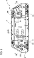
FIG. 2 is a plan view of the power supply device shown inFIG. 1 . -
FIG. 3 is a sectional view of the power supply device shown inFIG. 2 taken along line III-III. -
FIG. 4 is a schematic vertical sectional view of a power supply device according to an exemplary embodiment of the present invention. -
FIG. 5 is a schematic vertical sectional view of a power supply device according to another exemplary embodiment of the present invention. -
FIG. 6 is a schematic vertical sectional view of a conventional power supply device. - Hereinafter, an exemplary embodiment of the present invention will be described with reference to the drawings. It is to be noted, however, that the exemplary embodiments described below are illustrations each embodying a technical idea of the present invention, and the present invention is not specifically limited to the following exemplary embodiments. The components recited in the claims are not limited to the components described in the exemplary embodiments. In particular, it is not intended to limit the scope of the present invention to sizes, materials, shapes, relative arrangement, and the like of the components, which are described in the exemplary embodiments, unless otherwise specified. The sizes and the like are mere explanation examples. The sizes and the positional relation of the components in the drawings may be exaggerated for clearing the explanation in some cases. Components that are identical or of the same quality have the same names and the same reference marks in the following description, and detailed descriptions of these components are omitted where appropriate. Regarding elements that constitute the present invention, one component may constitute a plurality of elements of the elements, or one component may serve as a plurality of elements of the elements. On the other hand, a function of one component may be shared by a plurality of components. Contents described in some examples or some of the exemplary embodiments can be used, for example, in the other examples or exemplary embodiments. A vertical direction described in the specification is specified in the drawings.
- The power supply device shown in
FIGS. 1 to 4 includesbattery block 3, in which a plurality ofsecondary batteries 1 is disposed in fixed positions bybattery holder 2, andcircuit board 4 that is non-heat resistingmember 10 disposed facingbattery block 3. -
Secondary battery 1 is a lithium-ion battery. Assecondary battery 1, a non-aqueous electrolyte secondary battery including an exhaust valve can be alternatively used other than a lithium-ion battery. Further, assecondary battery 1, any other types of secondary battery including an exhaust valve currently used or to be developed can be alternatively used instead of a lithium-ion battery. -
Secondary battery 1 is a cylindrical battery in which a battery case includes an exterior can whose opening is sealed with a sealing plate, and is filled with a spirally wound electrode and electrolyte. Insecondary battery 1, positive and negative electrodes are provided on the sealing plate and a bottom surface of the exterior can. In addition, insecondary battery 1, an exhaust valve is provided on the sealing plate or at the bottom surface of the exterior can. The exhaust valve opens when an internal pressure is higher than a set pressure, and discharges gas to inside so as to prevent the battery case from being destroyed. - The internal pressure of
secondary battery 1 may abnormally increase when being charged with or discharging a large current, or being used under a severe external condition.Secondary battery 1 whose internal pressure may abnormally increase includes an exhaust valve (not shown) to prevent rupture. The exhaust valve opens when the internal pressure is more than or equal to the set pressure so as to prevent the rupture due to the increase in the internal pressure. When the exhaust valve ofsecondary battery 1 is open, a temperature ofsecondary battery 1 is considerably high. Accordingly, the temperature of the exhaust gas discharged from the exhaust valve that is open is considerably high. In particular, the temperature of a lithium-ion battery may exceed 500 °C. -
Battery block 3 configured of the plurality ofsecondary batteries 1 has a structure in whichsecondary batteries 1 are arranged in parallel, exhaust-side end surfaces 1A, on which an exhaust valve is provided, are disposed on a same plane, and exhaust-side end surfaces 1A each are provided withair layer 5 so that the exhaust gas discharged from the exhaust valve that opens is discharged intoair layer 5.Battery block 3 has respectivesecondary batteries 1 disposed in fixed positions by means ofbattery holder 2.Battery holder 2 disposes both end surfaces ofsecondary batteries 1 on the same planes such that bus bars 11, which are metal sheets, can be connected to the positive and negative electrodes provided at respective ends ofsecondary batteries 1, and exhaust-side end surfaces 1A are on the same plane. Thisbattery holder 2 is produced through molding of a thermoplastic resin. - In
battery holder 2, electrode covers 21 that cover both end surfaces of respectivesecondary batteries 1 whose both ends are disposed on the same planes are integrally molded withinsertion cylinders 22 into which respectivesecondary batteries 1 are inserted and disposed in fixed positions. On a surface ofelectrode cover 21, fittingrecess 23 is formed for guidingbus bar 11, which is a metal sheet, and disposingbus bar 11 in a fixed position. In addition,electrode cover 21 haselectrode window 24, which is an opening for connectingbus bar 11 to an electrode provided on an end surface of each ofsecondary batteries 1.Electrode window 24 is disposed in a position where a middle portion of the electrode of each ofsecondary batteries 1 is exposed.Bus bar 11, which is a metal sheet, is welded and connected to the electrode exposed toelectrode window 24. -
Bus bar 11 is set in fittingrecess 23 provided onelectrode cover 21 ofbattery holder 2, and disposed in a fixed position. In this state,bus bar 11 is connected to the electrode by a method such as spot welding, laser welding, or ultrasonic welding.Bus bar 11 connectssecondary batteries 1 that are adjacent to each other in parallel or in series. - In the power supply device shown in
FIGS. 1 to 4 ,circuit board 4, which is an important component, is disposed facingbattery block 3.Circuit board 4 is non-heat resistingmember 10 that does not have heat resistance to endure high-temperature exhaust gas discharged from the exhaust valve.Circuit board 4 is mounted with an electronic component on an epoxy resin plate reinforced mainly by glass fibers. Thiscircuit board 4 is mounted with an electronic component that provides a protection circuit that blocks or controls a current through detection of the current that charges or is discharged fromsecondary battery 1 or a temperature, a computing circuit that calculates a remaining capacity through calculation of a charging or discharging current ofsecondary battery 1, or the like. When being damaged by high-temperature exhaust gas, thiscircuit board 4 cannot guarantee normal operation of the protection circuit or the computing circuit. Therefore, it is very important to preventcircuit board 4, which is non-heat resistingmember 10 and an important component, from being damaged even when the exhaust valve is open and the exhaust gas is emitted. In order to protectcircuit board 4 from the exhaust gas, the power supply device shown inFIGS. 3 and4 providesair layer 5 and heat-blocking layer 6 betweenbattery block 3 andcircuit board 4.Air layer 5 isexhaust duct 5A that discharges the exhaust gas from the exhaust valve to the outside. Heat-blocking layer 6 has a layered structure ofmolten layer 7 and insulatinglayer 8, and protects non-heat resistingmember 10 such ascircuit board 4 from high-temperature exhaust gas discharged fromsecondary battery 1 intoexhaust duct 5A. - Heat-
blocking layer 6 protectscircuit board 4 from the high-temperature exhaust gas discharged fromsecondary battery 1 intoair layer 5. An exhaust valve is provided on one end surface ofsecondary battery 1, and this end surface is exhaust-side end surface 1A. In a cylindrical battery, an exhaust valve is provided on a bottom surface of an exterior can or on a sealing plate. Therefore, for a secondary battery in which an exhaust valve is provided on the bottom surface of the exterior can, the bottom surface of the exterior can is the exhaust-side end surface, whereas forsecondary battery 1 in which an exhaust valve is provided on the sealing plate, the side of the sealing plate is exhaust-side end surface 1A. -
Battery block 3 does not necessarily have all of exhaust-side end surfaces 1A ofsecondary batteries 1 disposed on the same plane.Battery block 3 hassecondary batteries 1 connected in parallel so as to face the same direction, andsecondary batteries 1 connected in series so as to be alternately opposite to each other. As shown in the sectional view ofFIG. 3 ,battery block 3 has adjacentsecondary batteries 1 so as to be alternately opposed to each other and connected in series. Therefore,circuit board 4 is disposed facing some of exhaust-side end surfaces 1A ofsecondary batteries 1. The exhaust gas discharged from exhaust-side end surface 1A ofsecondary battery 1 is discharged intoair layer 5. In order to protectcircuit board 4, which is an important component, from the high-temperature gas discharged intoair layer 5, heat-blocking layer 6 is provided betweenair layer 5 andcircuit board 4. -
Molten layer 7 of heat-blocking layer 6 is subject to thermal decomposition, a chemical reaction, or a layer change by the heat energy of the exhaust gas discharged intoair layer 5 to absorb the heat energy of the exhaust gas.Molten layer 7 does not absorb the heat energy of the exhaust gas through an increase in the temperature ofmolten layer 7 itself. Instead,molten layer 7 absorbs the heat energy of the exhaust gas through thermal decomposition, a chemical reaction, or a layer change ofmolten layer 7 itself. When an object absorbs heat energy through an increase in the temperature of the object itself, the heat energy is proportional to specific heat. In contrast, when an object absorbs the heat energy through thermal decomposition, a chemical reaction, or a layer change of the object itself, the heat energy is proportional to heat of evaporation incomparable with specific heat, and thus is extremely large.Molten layer 7 that absorbs a large amount of heat energy can remarkably reduce the temperature of the high-temperature exhaust gas. - Moreover, the power supply device of
FIGS. 3 and4 has two-layeredmolten layer 7 formed of firstmolten layer 7A and secondmolten layer 7B stacked on both surfaces of insulatinglayer 8, where firstmolten layer 7A is stacked between insulatinglayer 8 andair layer 5, whereas secondmolten layer 7B is stacked between insulatinglayer 8 andcircuit board 4. Firstmolten layer 7A isbottom plate 9A ofsubstrate holder 9 forming a thermoplastic resin. Firstmolten layer 7A that is also used assubstrate holder 9 forms the thermoplastic resin into a box shape having an upper opening and provided withside walls 9B aroundbottom plate 9A, and allowscircuit board 4 to be disposed in a fixed position on a top surface ofbottom plate 9A.Substrate holder 9 allowscircuit board 4 to be disposed in the fixed position so as to protectcircuit board 4 from the high-temperature exhaust gas withbottom plate 9A, which is firstmolten layer 7A. Firstmolten layer 7A that is also used assubstrate holder 9 is formed of a thermoplastic resin having a melting point or thermal decomposition temperature of 400 °C or less such as polyethylene, polypropylene, an acrylonitrile-butadiene-styrene (ABS) resin, polycarbonate, and an acrylic resin. - Second
molten layer 7B isurethane potting resin 12. Pottingresin 12 that has not been cured and is liquid is filled insubstrate holder 9, and provided betweeninsulating layer 8 andcircuit board 4. Pottingresin 12 that has not been cured is injected intobattery holder 2, intrudes into a gap between insulatinglayer 8 andcircuit board 4, and is brought into close contact with insulatinglayer 8 andcircuit board 4. Pottingresin 12 that has not been cured is injected intosubstrate holder 9 after insulatinglayer 8 is stacked onbottom plate 9A ofsubstrate holder 9 andcircuit board 4 is fixed in a fixed position. - Insulating
layer 8 is a layer having heat-insulating properties of not being deformed by the high-temperature exhaust gas discharged from the exhaust valve, preferably heat-insulating properties of not being deformed at 600°C, and isfiber sheet 13 having heat resistance in which heat-resistant fibers such as inorganic fibers, carbon fibers, or metal fibers are three-dimensionally aggregated. Alternatively, a board having heat resistance and heat insulation such as an inorganic board or metal sheet can be used for insulatinglayer 8. - First
molten layer 7A is subject to thermal decomposition, a chemical reaction, or a layer change by the heat energy of the exhaust gas. Therefore, the exhaust gas may penetrate firstmolten layer 7A. If the exhaust gas penetrates heat-blocking layer 6,circuit board 4, which is an important component, is damaged. Therefore, insulatinglayer 8 is not deformed by the exhaust gas, inhibits the penetration of the exhaust gas, and further insulates the heat to prevent an increase in the temperature ofcircuit board 4 due to the exhaust gas. Firstmolten layer 7A absorbs the heat energy of the exhaust gas through thermal decomposition, a chemical reaction, or a layer change of firstmolten layer 7A itself. Therefore, firstmolten layer 7A can increase the heat energy to be absorbed. Sincemolten layer 7 absorbs the heat energy through a modification ofmolten layer 7 itself, the exhaust gas may penetratemolten layer 7. However, insulatinglayer 8 stacked onmolten layer 7 surely inhibits the penetration of the exhaust gas even if heat energy that insulatinglayer 8 can absorb is smaller than heat energy that moltenlayer 7 can absorb. Secondmolten layer 7B does not directly come into contact with the exhaust gas because of insulatinglayer 8 disposed between secondmolten layer 7B andair layer 5, but is disposed so as to be thermally connected with insulatinglayer 8. Accordingly, when insulatinglayer 8 has a high temperature, secondmolten layer 7B absorbs heat from insulatinglayer 8 through thermal decomposition, a chemical reaction, or a layer change of secondmolten layer 7B itself, and decreases the heat energy transferred tocircuit board 4 so as to more surely protectcircuit board 4. - As described above, heat-
blocking layer 6 that has moltenlayer 7 and insulatinglayer 8 being stacked efficiently absorbs the heat energy of the exhaust gas withmolten layer 7 so as to decrease the temperature of the exhaust gas, and inhibits the penetration of the exhaust gas with insulatinglayer 8 so as to insulate the heat. As a result,circuit board 4 can be surely prevented from being damaged by the high-temperature exhaust gas. In particular, as shown inFIGS. 3 and4 , heat-blocking layer 6, which has two-layeredmolten layer 7 stacked on both surfaces of insulatinglayer 8 where firstmolten layer 7A and secondmolten layer 7B are in close contact with both surfaces of insulatinglayer 8, decreases the temperature of the exhaust gas by absorbing the heat energy of the exhaust gas discharged intoair layer 5 with both of firstmolten layer 7A and secondmolten layer 7B, and further inhibits the penetration of the exhaust gas with insulatinglayer 8. As a result, heat-blocking layer 6 can ideally protectcircuit board 4, and surely inhibitcircuit board 4 from being damaged. However, in the power supply device of the present invention,molten layer 7 does not have to be stacked on both surfaces of insulatinglayer 8 to form heat-blocking layer 6. Alternatively, for example, only the first molten layer may be stacked on the insulating layer such that the heat-blocking layer has a two-layered structure of a molten layer and an insulating layer. This molten layer may be formed into a sheet without being a substrate holder, and the circuit board may be disposed on top of the sheet with the insulating layer interposed. - The power supply device of
FIG. 3 is provided withair layer 5 on an upper surface ofbattery block 3 and betweenbattery block 3 and heat-blocking layer 6. In the power supply device of this figure, firstmolten layer 7A isbottom plate 9A ofsubstrate holder 9. Therefore, a gap is provided between the surfaces ofbottom plate 9A ofsubstrate holder 9 andbattery block 3 facing each other to formair layer 5. In this structure,air layer 5 can be formed by disposingsubstrate holder 9 away frombattery block 3. The structure in whichsubstrate holder 9 is fixed with a gap provided betweensubstrate holder 9 andbattery block 3 can be achieved, as shown inFIGS. 1 and3 , by providingbattery holder 2 ofbattery block 3 with a plurality of protrudedribs 25 integrally molded to protrude towardbottom plate 9A ofsubstrate holder 9.Protruded rib 25 protrudes from a surface ofelectrode cover 21 ofbattery holder 2 that covers exhaust-side end surface 1A ofsecondary battery 1.Protruded rib 25 may protrude frombottom plate 9A ofsubstrate holder 9 towardelectrode cover 21 ofbattery holder 2. Alternatively, protrudedrib 25 may be configured as an independent component. In this structure,air layer 5 can be provided betweenbattery block 3 andbottom plate 9A ofsubstrate holder 9 by protrudedrib 25. Therefore, a vertical width ofair layer 5 can be accurately specified by a protruding height of protrudedrib 25. Sincebottom plate 9A ofsubstrate holder 9 constitutes firstmolten layer 7A of heat-blocking layer 6,air layer 5 is provided between firstmolten layer 7A and electrode cover 21 ofbattery holder 2.Electrode cover 21 ofbattery holder 2 that covers exhaust-side end surface 1A ofsecondary battery 1 is disposed on a surface ofbattery block 3 facingair layer 5. Through screwing of a set screw (not shown) that penetratessubstrate holder 9 to protrudedrib 25,substrate holder 9 can be fixed to a fixed position ofbattery holder 2 ofbattery block 3. - However, although not shown, without using the set screw that penetrates the substrate holder, the air layer can be provided through disposition of the protruded rib between the bottom plate of the substrate holder and the battery block. For example, the circuit board can be fixed to the fixed position via a lead plate fixed to the circuit board, and the circuit board and the substrate holder can be disposed in the fixed positions via the potting resin, which is the second molten layer. For the lead plate fixed to the circuit board, a thick metal sheet is used having a low resistance so as to reduce a voltage drop through a supply of a large current. A thick metal sheet can stably fix the circuit board to the battery block. Therefore, the circuit board and the substrate holder can be disposed in specified positions of the battery block via the lead plate. Moreover, the circuit board can be disposed in the fixed position of the battery block via the lead plate, and further, the substrate holder can be disposed in the fixed position through screwing of the substrate holder to the battery block.
- In the above-mentioned power supply device, non-heat resisting
member 10 iscircuit board 4. However, as shown inFIG. 5 , in the power supply device in which battery blocks 3 are disposed in a plurality of rows, non-heat resistingmember 10 isbattery block 3 that is stacked. In the power supply device ofFIG. 5 ,air layer 5 and heat-blocking layer 6 are provided betweenbattery blocks 3 so as to prevent exhaust gas discharged fromsecondary battery 1 of one ofbattery blocks 3 from damaging another of battery blocks 3. In the power supply device includingbattery blocks 3 stacked in the plurality of rows, exhaust gas is discharged from respective battery blocks 3. Therefore,air layer 5 is provided on sides ofrespective battery blocks 3, and heat-blocking layer 6 is provided betweenair layers 5 provided on the sides ofrespective battery blocks 3 so as to prevent the exhaust gas discharged fromsecondary battery 1 of one ofbattery blocks 3 from damaging the other of battery blocks 3. - The power supply device according to the present invention is a power supply device including a plurality of secondary batteries including an exhaust valve, and can be advantageously used in applications that require a high level of safety.
-
- 1:
- secondary battery
- 1A:
- exhaust-side end surface
- 2:
- battery holder
- 3:
- battery block
- 4:
- circuit board
- 5:
- air layer
- 6:
- heat-blocking layer
- 7:
- molten layer
- 7A:
- first molten layer
- 7B:
- second molten layer
- 8:
- insulating layer
- 9:
- substrate holder
- 9A:
- bottom plate
- 9B:
- side wall
- 10:
- non-heat resisting member
- 11:
- bus bar
- 12:
- potting resin
- 13:
- fiber sheet
- 21:
- electrode cover
- 22:
- insertion cylinder
- 23:
- fitting recess
- 24:
- electrode window
- 25:
- protruded rib
- 101:
- secondary battery
- 101A:
- exhaust-side end surface
- 104:
- circuit board
- 105:
- exhaust duct
- 107:
- molten layer
- 107A:
- potting resin
Claims (12)
- A power supply device configured of a battery block and a non-heat resisting member facing the battery block with a heat-blocking layer including a molten layer interposed between the battery block and the non-heat resisting member, the battery block having a plurality of secondary batteries that are disposed in fixed positions by a battery holder and each have an exhaust valve that opens on an exhaust-side end surface when an internal pressure increases to a set pressure, the non-heat resisting member being formed of a circuit board or any of a plurality of secondary batteries,
the battery block having the secondary batteries disposed in parallel, with some of or all exhaust-side end surfaces of the secondary batteries disposed facing the non-heat resisting member,
with an air layer disposed between the battery block and the heat-blocking layer,
wherein
the heat-blocking layer has a layered structure of the molten layer and an insulating layer having heat-insulating properties of not being deformed by exhaust gas from the exhaust valve, the insulating layer being stacked on the molten layer, and
the heat-blocking layer having the layered structure of the molten layer and the insulating layer is disposed between the air layer and the non-heat resisting member. - The power supply device according to claim 1, wherein
the molten layer is formed of a first molten layer and a second molten layer, the first molten layer is disposed closer to the air layer than the insulating layer, and the second molten layer is disposed closer to the non-heat resisting member than the insulating layer. - The power supply device according to claim 2, wherein
the first molten layer is a layer subject to thermal decomposition, a chemical reaction, or a layer change by heat energy of exhaust gas discharged from the exhaust valve to absorb the heat energy of the exhaust gas. - The power supply device according to claim 2, wherein
the second molten layer is a layer subject to thermal decomposition, a chemical reaction, or a layer change by heat energy of exhaust gas discharged from the exhaust valve to absorb the heat energy of the exhaust gas. - The power supply device according to claim 4, wherein
the second molten layer is a potting resin. - The power supply device according to claim 4 or 5, wherein
the non-heat resisting member is a circuit board, and
the first molten layer is a plastic substrate holder. - The power supply device according to any one of claims 1 to 6, wherein
the insulating layer is a fiber sheet formed of an aggregate of fibers. - The power supply device according to any one of claims 1 to 6, wherein
the insulating layer is an inorganic board. - The power supply device according to claim 7, wherein
the insulating layer is a metal sheet. - The power supply device according to any one of claims 1 to 9, wherein
the battery holder includes a protruded rib protruding toward the heat-blocking layer and providing the air layer, and with the protruded rib, the air layer is provided between the battery holder and the heat-blocking layer. - The power supply device according to any one of claims 1 to 5, and 7 to 10, wherein
the non-heat resisting member is a battery block disposed facing the battery block. - The power supply device according to any one of claims 1 to 11, wherein
the air layer is an exhaust duct that discharges exhaust gas from the exhaust valve to an outside.
Applications Claiming Priority (2)
| Application Number | Priority Date | Filing Date | Title |
|---|---|---|---|
| JP2017143559A JP2020161210A (en) | 2017-07-25 | 2017-07-25 | Power supply device |
| PCT/JP2018/026691 WO2019021881A1 (en) | 2017-07-25 | 2018-07-17 | Power supply device |
Publications (3)
| Publication Number | Publication Date |
|---|---|
| EP3660945A1 true EP3660945A1 (en) | 2020-06-03 |
| EP3660945A4 EP3660945A4 (en) | 2020-07-29 |
| EP3660945B1 EP3660945B1 (en) | 2022-12-28 |
Family
ID=65041176
Family Applications (1)
| Application Number | Title | Priority Date | Filing Date |
|---|---|---|---|
| EP18838146.1A Active EP3660945B1 (en) | 2017-07-25 | 2018-07-17 | Power supply device |
Country Status (3)
| Country | Link |
|---|---|
| EP (1) | EP3660945B1 (en) |
| JP (1) | JP2020161210A (en) |
| WO (1) | WO2019021881A1 (en) |
Cited By (6)
| Publication number | Priority date | Publication date | Assignee | Title |
|---|---|---|---|---|
| CN113067077A (en) * | 2021-03-27 | 2021-07-02 | 安徽相成新能源科技有限公司 | Power battery thermal management system |
| US20230062907A1 (en) * | 2020-01-30 | 2023-03-02 | Makita Corporation | Battery apparatus |
| US11677116B2 (en) | 2019-04-05 | 2023-06-13 | Makita Corporation | Battery pack |
| US20230402705A1 (en) * | 2022-06-10 | 2023-12-14 | Diehl Ako Stiftung & Co. Kg | Cell contacting system, and energy storage device |
| WO2023237427A1 (en) * | 2022-06-10 | 2023-12-14 | Diehl Ako Stiftung & Co. Kg | Cell-contacting system and energy accumulator |
| SE546145C2 (en) * | 2023-07-26 | 2024-06-11 | Ab Solask Energi | Battery module and battery cabinet |
Families Citing this family (7)
| Publication number | Priority date | Publication date | Assignee | Title |
|---|---|---|---|---|
| EP4007047A4 (en) * | 2019-07-29 | 2022-11-09 | SANYO Electric Co., Ltd. | BATTERY PACK |
| JP7461723B2 (en) * | 2019-07-30 | 2024-04-04 | パナソニックエナジー株式会社 | Power Supplies |
| JP7507002B2 (en) * | 2020-04-24 | 2024-06-27 | パナソニックエナジー株式会社 | Battery pack |
| DE102020111453A1 (en) | 2020-04-27 | 2021-10-28 | Audi Aktiengesellschaft | Energy storage cell |
| EP4411956A4 (en) * | 2021-09-30 | 2025-01-15 | Panasonic Intellectual Property Management Co., Ltd. | ELECTRICAL ENERGY STORAGE MODULE |
| DE102023128528A1 (en) * | 2023-10-18 | 2025-04-24 | Diehl Advanced Mobility GmbH | Arrangement for an energy storage module and method for assembling the arrangement |
| JP2026042399A (en) * | 2024-08-27 | 2026-03-11 | 株式会社Aescジャパン | Battery pack |
Family Cites Families (9)
| Publication number | Priority date | Publication date | Assignee | Title |
|---|---|---|---|---|
| JP2010009910A (en) * | 2008-06-26 | 2010-01-14 | Sanyo Electric Co Ltd | Battery pack |
| JP5300416B2 (en) * | 2008-10-31 | 2013-09-25 | 三洋電機株式会社 | Battery system |
| TWI419391B (en) * | 2009-12-25 | 2013-12-11 | Ind Tech Res Inst | Protection structure for preventing thermal dissipation and thermal runaway diffusion in battery system |
| CN102959761A (en) * | 2010-06-30 | 2013-03-06 | 松下电器产业株式会社 | Battery module |
| WO2012133710A1 (en) * | 2011-03-31 | 2012-10-04 | 三洋電機株式会社 | Power supply and vehicle comprising same |
| JP5341156B2 (en) | 2011-09-06 | 2013-11-13 | 三洋電機株式会社 | Power supply |
| ITBO20120184A1 (en) * | 2012-04-06 | 2013-10-07 | Ferrari Spa | ELECTRIC ENERGY STORAGE SYSTEM FOR A VEHICLE WITH ELECTRIC PROPULSION AND PRESENTING CYLINDRICAL CHEMICAL BATTERIES INSERTED IN A PLASTIC SUPPORTING MATRIX |
| JP6189301B2 (en) * | 2012-08-09 | 2017-08-30 | 三洋電機株式会社 | Power supply device, electric vehicle including the same, and power storage device |
| WO2014184993A1 (en) * | 2013-05-15 | 2014-11-20 | 三洋電機株式会社 | Battery pack and battery pack manufacturing method |
-
2017
- 2017-07-25 JP JP2017143559A patent/JP2020161210A/en active Pending
-
2018
- 2018-07-17 EP EP18838146.1A patent/EP3660945B1/en active Active
- 2018-07-17 WO PCT/JP2018/026691 patent/WO2019021881A1/en not_active Ceased
Cited By (7)
| Publication number | Priority date | Publication date | Assignee | Title |
|---|---|---|---|---|
| US11677116B2 (en) | 2019-04-05 | 2023-06-13 | Makita Corporation | Battery pack |
| US20230062907A1 (en) * | 2020-01-30 | 2023-03-02 | Makita Corporation | Battery apparatus |
| CN113067077A (en) * | 2021-03-27 | 2021-07-02 | 安徽相成新能源科技有限公司 | Power battery thermal management system |
| US20230402705A1 (en) * | 2022-06-10 | 2023-12-14 | Diehl Ako Stiftung & Co. Kg | Cell contacting system, and energy storage device |
| WO2023237427A1 (en) * | 2022-06-10 | 2023-12-14 | Diehl Ako Stiftung & Co. Kg | Cell-contacting system and energy accumulator |
| SE546145C2 (en) * | 2023-07-26 | 2024-06-11 | Ab Solask Energi | Battery module and battery cabinet |
| SE2350929A1 (en) * | 2023-07-26 | 2024-06-11 | Ab Solask Energi | Battery module and battery cabinet |
Also Published As
| Publication number | Publication date |
|---|---|
| WO2019021881A1 (en) | 2019-01-31 |
| JP2020161210A (en) | 2020-10-01 |
| EP3660945A4 (en) | 2020-07-29 |
| EP3660945B1 (en) | 2022-12-28 |
Similar Documents
| Publication | Publication Date | Title |
|---|---|---|
| EP3660945B1 (en) | Power supply device | |
| JP7418410B2 (en) | battery module | |
| KR102422278B1 (en) | battery system | |
| JP7621257B2 (en) | Battery pack | |
| US11811039B2 (en) | Battery pack | |
| JP6505259B2 (en) | battery pack | |
| US20210167456A1 (en) | Battery pack | |
| KR102366268B1 (en) | Battery Pack Having Insulation Tube | |
| JP5357987B2 (en) | Battery fire protection device | |
| JP7531968B2 (en) | Battery pack with heat diffusion suppression structure | |
| JP4501157B2 (en) | Secondary battery pack | |
| JP7619947B2 (en) | Battery pack | |
| KR20220125097A (en) | Battery module and battery pack including same | |
| US20210391625A1 (en) | Battery module | |
| US12142785B2 (en) | Battery pack | |
| KR20230052657A (en) | Battery Module With Insulation Pad Comprising Cooling and Fire Extinguishing Functions | |
| KR101773333B1 (en) | Secondary battery and battery module having the same | |
| EP2846378B1 (en) | Rechargeable battery having a fuse | |
| KR102867400B1 (en) | Battery module and battery pack including the same | |
| US20080299445A1 (en) | Secondary battery pack | |
| KR102943339B1 (en) | Battery module with a compartmentalized cell support structure | |
| US20250118844A1 (en) | Battery pack | |
| KR102179685B1 (en) | Chip thermistor heating pad of battery pack for polymer cell temperature detecting | |
| JP4496997B2 (en) | Secondary battery mounting structure | |
| KR20230054115A (en) | Battery Module With Digestive Tract Plate And Battery Pack Including It |
Legal Events
| Date | Code | Title | Description |
|---|---|---|---|
| STAA | Information on the status of an ep patent application or granted ep patent |
Free format text: STATUS: THE INTERNATIONAL PUBLICATION HAS BEEN MADE |
|
| PUAI | Public reference made under article 153(3) epc to a published international application that has entered the european phase |
Free format text: ORIGINAL CODE: 0009012 |
|
| STAA | Information on the status of an ep patent application or granted ep patent |
Free format text: STATUS: REQUEST FOR EXAMINATION WAS MADE |
|
| 17P | Request for examination filed |
Effective date: 20200120 |
|
| AK | Designated contracting states |
Kind code of ref document: A1 Designated state(s): AL AT BE BG CH CY CZ DE DK EE ES FI FR GB GR HR HU IE IS IT LI LT LU LV MC MK MT NL NO PL PT RO RS SE SI SK SM TR |
|
| AX | Request for extension of the european patent |
Extension state: BA ME |
|
| A4 | Supplementary search report drawn up and despatched |
Effective date: 20200630 |
|
| RIC1 | Information provided on ipc code assigned before grant |
Ipc: H01M 2/12 20060101ALI20200624BHEP Ipc: H01M 10/655 20140101ALI20200624BHEP Ipc: H01M 10/613 20140101ALI20200624BHEP Ipc: H01M 2/10 20060101AFI20200624BHEP Ipc: H01M 10/667 20140101ALI20200624BHEP Ipc: H01M 10/0525 20100101ALI20200624BHEP |
|
| DAV | Request for validation of the european patent (deleted) | ||
| DAX | Request for extension of the european patent (deleted) | ||
| REG | Reference to a national code |
Ref country code: DE Ref legal event code: R079 Ref document number: 602018044849 Country of ref document: DE Free format text: PREVIOUS MAIN CLASS: H01M0002100000 Ipc: H01M0050200000 |
|
| GRAP | Despatch of communication of intention to grant a patent |
Free format text: ORIGINAL CODE: EPIDOSNIGR1 |
|
| RIC1 | Information provided on ipc code assigned before grant |
Ipc: H01M 10/0525 20100101ALI20220706BHEP Ipc: H01M 10/667 20140101ALI20220706BHEP Ipc: H01M 10/655 20140101ALI20220706BHEP Ipc: H01M 10/613 20140101ALI20220706BHEP Ipc: H01M 50/30 20210101ALI20220706BHEP Ipc: H01M 50/20 20210101AFI20220706BHEP |
|
| STAA | Information on the status of an ep patent application or granted ep patent |
Free format text: STATUS: GRANT OF PATENT IS INTENDED |
|
| INTG | Intention to grant announced |
Effective date: 20220811 |
|
| RIN1 | Information on inventor provided before grant (corrected) |
Inventor name: HATTORI KIYOHISA Inventor name: MURAMATSU KOICHI Inventor name: HAINO MASAMI |
|
| GRAS | Grant fee paid |
Free format text: ORIGINAL CODE: EPIDOSNIGR3 |
|
| GRAA | (expected) grant |
Free format text: ORIGINAL CODE: 0009210 |
|
| STAA | Information on the status of an ep patent application or granted ep patent |
Free format text: STATUS: THE PATENT HAS BEEN GRANTED |
|
| AK | Designated contracting states |
Kind code of ref document: B1 Designated state(s): AL AT BE BG CH CY CZ DE DK EE ES FI FR GB GR HR HU IE IS IT LI LT LU LV MC MK MT NL NO PL PT RO RS SE SI SK SM TR |
|
| REG | Reference to a national code |
Ref country code: GB Ref legal event code: FG4D |
|
| REG | Reference to a national code |
Ref country code: CH Ref legal event code: EP |
|
| REG | Reference to a national code |
Ref country code: DE Ref legal event code: R096 Ref document number: 602018044849 Country of ref document: DE |
|
| REG | Reference to a national code |
Ref country code: AT Ref legal event code: REF Ref document number: 1541045 Country of ref document: AT Kind code of ref document: T Effective date: 20230115 |
|
| REG | Reference to a national code |
Ref country code: IE Ref legal event code: FG4D |
|
| REG | Reference to a national code |
Ref country code: LT Ref legal event code: MG9D |
|
| PG25 | Lapsed in a contracting state [announced via postgrant information from national office to epo] |
Ref country code: SE Free format text: LAPSE BECAUSE OF FAILURE TO SUBMIT A TRANSLATION OF THE DESCRIPTION OR TO PAY THE FEE WITHIN THE PRESCRIBED TIME-LIMIT Effective date: 20221228 Ref country code: NO Free format text: LAPSE BECAUSE OF FAILURE TO SUBMIT A TRANSLATION OF THE DESCRIPTION OR TO PAY THE FEE WITHIN THE PRESCRIBED TIME-LIMIT Effective date: 20230328 Ref country code: LT Free format text: LAPSE BECAUSE OF FAILURE TO SUBMIT A TRANSLATION OF THE DESCRIPTION OR TO PAY THE FEE WITHIN THE PRESCRIBED TIME-LIMIT Effective date: 20221228 Ref country code: FI Free format text: LAPSE BECAUSE OF FAILURE TO SUBMIT A TRANSLATION OF THE DESCRIPTION OR TO PAY THE FEE WITHIN THE PRESCRIBED TIME-LIMIT Effective date: 20221228 |
|
| REG | Reference to a national code |
Ref country code: NL Ref legal event code: MP Effective date: 20221228 |
|
| REG | Reference to a national code |
Ref country code: AT Ref legal event code: MK05 Ref document number: 1541045 Country of ref document: AT Kind code of ref document: T Effective date: 20221228 |
|
| PG25 | Lapsed in a contracting state [announced via postgrant information from national office to epo] |
Ref country code: RS Free format text: LAPSE BECAUSE OF FAILURE TO SUBMIT A TRANSLATION OF THE DESCRIPTION OR TO PAY THE FEE WITHIN THE PRESCRIBED TIME-LIMIT Effective date: 20221228 Ref country code: LV Free format text: LAPSE BECAUSE OF FAILURE TO SUBMIT A TRANSLATION OF THE DESCRIPTION OR TO PAY THE FEE WITHIN THE PRESCRIBED TIME-LIMIT Effective date: 20221228 Ref country code: HR Free format text: LAPSE BECAUSE OF FAILURE TO SUBMIT A TRANSLATION OF THE DESCRIPTION OR TO PAY THE FEE WITHIN THE PRESCRIBED TIME-LIMIT Effective date: 20221228 Ref country code: GR Free format text: LAPSE BECAUSE OF FAILURE TO SUBMIT A TRANSLATION OF THE DESCRIPTION OR TO PAY THE FEE WITHIN THE PRESCRIBED TIME-LIMIT Effective date: 20230329 |
|
| PG25 | Lapsed in a contracting state [announced via postgrant information from national office to epo] |
Ref country code: NL Free format text: LAPSE BECAUSE OF FAILURE TO SUBMIT A TRANSLATION OF THE DESCRIPTION OR TO PAY THE FEE WITHIN THE PRESCRIBED TIME-LIMIT Effective date: 20221228 |
|
| PG25 | Lapsed in a contracting state [announced via postgrant information from national office to epo] |
Ref country code: SM Free format text: LAPSE BECAUSE OF FAILURE TO SUBMIT A TRANSLATION OF THE DESCRIPTION OR TO PAY THE FEE WITHIN THE PRESCRIBED TIME-LIMIT Effective date: 20221228 Ref country code: RO Free format text: LAPSE BECAUSE OF FAILURE TO SUBMIT A TRANSLATION OF THE DESCRIPTION OR TO PAY THE FEE WITHIN THE PRESCRIBED TIME-LIMIT Effective date: 20221228 Ref country code: PT Free format text: LAPSE BECAUSE OF FAILURE TO SUBMIT A TRANSLATION OF THE DESCRIPTION OR TO PAY THE FEE WITHIN THE PRESCRIBED TIME-LIMIT Effective date: 20230428 Ref country code: ES Free format text: LAPSE BECAUSE OF FAILURE TO SUBMIT A TRANSLATION OF THE DESCRIPTION OR TO PAY THE FEE WITHIN THE PRESCRIBED TIME-LIMIT Effective date: 20221228 Ref country code: EE Free format text: LAPSE BECAUSE OF FAILURE TO SUBMIT A TRANSLATION OF THE DESCRIPTION OR TO PAY THE FEE WITHIN THE PRESCRIBED TIME-LIMIT Effective date: 20221228 Ref country code: CZ Free format text: LAPSE BECAUSE OF FAILURE TO SUBMIT A TRANSLATION OF THE DESCRIPTION OR TO PAY THE FEE WITHIN THE PRESCRIBED TIME-LIMIT Effective date: 20221228 Ref country code: AT Free format text: LAPSE BECAUSE OF FAILURE TO SUBMIT A TRANSLATION OF THE DESCRIPTION OR TO PAY THE FEE WITHIN THE PRESCRIBED TIME-LIMIT Effective date: 20221228 |
|
| PG25 | Lapsed in a contracting state [announced via postgrant information from national office to epo] |
Ref country code: SK Free format text: LAPSE BECAUSE OF FAILURE TO SUBMIT A TRANSLATION OF THE DESCRIPTION OR TO PAY THE FEE WITHIN THE PRESCRIBED TIME-LIMIT Effective date: 20221228 Ref country code: PL Free format text: LAPSE BECAUSE OF FAILURE TO SUBMIT A TRANSLATION OF THE DESCRIPTION OR TO PAY THE FEE WITHIN THE PRESCRIBED TIME-LIMIT Effective date: 20221228 Ref country code: IS Free format text: LAPSE BECAUSE OF FAILURE TO SUBMIT A TRANSLATION OF THE DESCRIPTION OR TO PAY THE FEE WITHIN THE PRESCRIBED TIME-LIMIT Effective date: 20230428 Ref country code: AL Free format text: LAPSE BECAUSE OF FAILURE TO SUBMIT A TRANSLATION OF THE DESCRIPTION OR TO PAY THE FEE WITHIN THE PRESCRIBED TIME-LIMIT Effective date: 20221228 |
|
| REG | Reference to a national code |
Ref country code: DE Ref legal event code: R097 Ref document number: 602018044849 Country of ref document: DE |
|
| PG25 | Lapsed in a contracting state [announced via postgrant information from national office to epo] |
Ref country code: DK Free format text: LAPSE BECAUSE OF FAILURE TO SUBMIT A TRANSLATION OF THE DESCRIPTION OR TO PAY THE FEE WITHIN THE PRESCRIBED TIME-LIMIT Effective date: 20221228 |
|
| PLBE | No opposition filed within time limit |
Free format text: ORIGINAL CODE: 0009261 |
|
| STAA | Information on the status of an ep patent application or granted ep patent |
Free format text: STATUS: NO OPPOSITION FILED WITHIN TIME LIMIT |
|
| 26N | No opposition filed |
Effective date: 20230929 |
|
| REG | Reference to a national code |
Ref country code: GB Ref legal event code: 732E Free format text: REGISTERED BETWEEN 20231116 AND 20231122 |
|
| PG25 | Lapsed in a contracting state [announced via postgrant information from national office to epo] |
Ref country code: SI Free format text: LAPSE BECAUSE OF FAILURE TO SUBMIT A TRANSLATION OF THE DESCRIPTION OR TO PAY THE FEE WITHIN THE PRESCRIBED TIME-LIMIT Effective date: 20221228 |
|
| PG25 | Lapsed in a contracting state [announced via postgrant information from national office to epo] |
Ref country code: MC Free format text: LAPSE BECAUSE OF FAILURE TO SUBMIT A TRANSLATION OF THE DESCRIPTION OR TO PAY THE FEE WITHIN THE PRESCRIBED TIME-LIMIT Effective date: 20221228 |
|
| PG25 | Lapsed in a contracting state [announced via postgrant information from national office to epo] |
Ref country code: MC Free format text: LAPSE BECAUSE OF FAILURE TO SUBMIT A TRANSLATION OF THE DESCRIPTION OR TO PAY THE FEE WITHIN THE PRESCRIBED TIME-LIMIT Effective date: 20221228 |
|
| REG | Reference to a national code |
Ref country code: CH Ref legal event code: PL |
|
| REG | Reference to a national code |
Ref country code: BE Ref legal event code: MM Effective date: 20230731 |
|
| PG25 | Lapsed in a contracting state [announced via postgrant information from national office to epo] |
Ref country code: LU Free format text: LAPSE BECAUSE OF NON-PAYMENT OF DUE FEES Effective date: 20230717 |
|
| PG25 | Lapsed in a contracting state [announced via postgrant information from national office to epo] |
Ref country code: LU Free format text: LAPSE BECAUSE OF NON-PAYMENT OF DUE FEES Effective date: 20230717 |
|
| REG | Reference to a national code |
Ref country code: IE Ref legal event code: MM4A |
|
| PG25 | Lapsed in a contracting state [announced via postgrant information from national office to epo] |
Ref country code: CH Free format text: LAPSE BECAUSE OF NON-PAYMENT OF DUE FEES Effective date: 20230731 |
|
| PG25 | Lapsed in a contracting state [announced via postgrant information from national office to epo] |
Ref country code: IT Free format text: LAPSE BECAUSE OF FAILURE TO SUBMIT A TRANSLATION OF THE DESCRIPTION OR TO PAY THE FEE WITHIN THE PRESCRIBED TIME-LIMIT Effective date: 20221228 Ref country code: BE Free format text: LAPSE BECAUSE OF NON-PAYMENT OF DUE FEES Effective date: 20230731 |
|
| PG25 | Lapsed in a contracting state [announced via postgrant information from national office to epo] |
Ref country code: IE Free format text: LAPSE BECAUSE OF NON-PAYMENT OF DUE FEES Effective date: 20230717 |
|
| PG25 | Lapsed in a contracting state [announced via postgrant information from national office to epo] |
Ref country code: IE Free format text: LAPSE BECAUSE OF NON-PAYMENT OF DUE FEES Effective date: 20230717 |
|
| PG25 | Lapsed in a contracting state [announced via postgrant information from national office to epo] |
Ref country code: BG Free format text: LAPSE BECAUSE OF FAILURE TO SUBMIT A TRANSLATION OF THE DESCRIPTION OR TO PAY THE FEE WITHIN THE PRESCRIBED TIME-LIMIT Effective date: 20221228 |
|
| PG25 | Lapsed in a contracting state [announced via postgrant information from national office to epo] |
Ref country code: BG Free format text: LAPSE BECAUSE OF FAILURE TO SUBMIT A TRANSLATION OF THE DESCRIPTION OR TO PAY THE FEE WITHIN THE PRESCRIBED TIME-LIMIT Effective date: 20221228 |
|
| PG25 | Lapsed in a contracting state [announced via postgrant information from national office to epo] |
Ref country code: CY Free format text: LAPSE BECAUSE OF FAILURE TO SUBMIT A TRANSLATION OF THE DESCRIPTION OR TO PAY THE FEE WITHIN THE PRESCRIBED TIME-LIMIT; INVALID AB INITIO Effective date: 20180717 |
|
| PG25 | Lapsed in a contracting state [announced via postgrant information from national office to epo] |
Ref country code: HU Free format text: LAPSE BECAUSE OF FAILURE TO SUBMIT A TRANSLATION OF THE DESCRIPTION OR TO PAY THE FEE WITHIN THE PRESCRIBED TIME-LIMIT; INVALID AB INITIO Effective date: 20180717 |
|
| REG | Reference to a national code |
Ref country code: DE Ref legal event code: R081 Ref document number: 602018044849 Country of ref document: DE Owner name: PANASONIC ENERGY CO., LTD., MORIGUCHI-SHI, JP Free format text: FORMER OWNER: SANYO ELECTRIC CO., LTD., DAITO-SHI, OSAKA, JP |
|
| PGFP | Annual fee paid to national office [announced via postgrant information from national office to epo] |
Ref country code: DE Payment date: 20250722 Year of fee payment: 8 |
|
| PGFP | Annual fee paid to national office [announced via postgrant information from national office to epo] |
Ref country code: GB Payment date: 20250722 Year of fee payment: 8 |
|
| PGFP | Annual fee paid to national office [announced via postgrant information from national office to epo] |
Ref country code: FR Payment date: 20250725 Year of fee payment: 8 |
|
| PG25 | Lapsed in a contracting state [announced via postgrant information from national office to epo] |
Ref country code: TR Free format text: LAPSE BECAUSE OF FAILURE TO SUBMIT A TRANSLATION OF THE DESCRIPTION OR TO PAY THE FEE WITHIN THE PRESCRIBED TIME-LIMIT Effective date: 20221228 |