EP3660940B1 - Battery and device - Google Patents
Battery and device Download PDFInfo
- Publication number
- EP3660940B1 EP3660940B1 EP19176841.5A EP19176841A EP3660940B1 EP 3660940 B1 EP3660940 B1 EP 3660940B1 EP 19176841 A EP19176841 A EP 19176841A EP 3660940 B1 EP3660940 B1 EP 3660940B1
- Authority
- EP
- European Patent Office
- Prior art keywords
- battery
- thickness
- layer
- electrode tab
- width
- Prior art date
- Legal status (The legal status is an assumption and is not a legal conclusion. Google has not performed a legal analysis and makes no representation as to the accuracy of the status listed.)
- Active
Links
Images


Classifications
-
- H—ELECTRICITY
- H01—ELECTRIC ELEMENTS
- H01M—PROCESSES OR MEANS, e.g. BATTERIES, FOR THE DIRECT CONVERSION OF CHEMICAL ENERGY INTO ELECTRICAL ENERGY
- H01M10/00—Secondary cells; Manufacture thereof
- H01M10/04—Construction or manufacture in general
- H01M10/0431—Cells with wound or folded electrodes
-
- H—ELECTRICITY
- H01—ELECTRIC ELEMENTS
- H01M—PROCESSES OR MEANS, e.g. BATTERIES, FOR THE DIRECT CONVERSION OF CHEMICAL ENERGY INTO ELECTRICAL ENERGY
- H01M10/00—Secondary cells; Manufacture thereof
- H01M10/04—Construction or manufacture in general
- H01M10/049—Processes for forming or storing electrodes in the battery container
-
- H—ELECTRICITY
- H01—ELECTRIC ELEMENTS
- H01M—PROCESSES OR MEANS, e.g. BATTERIES, FOR THE DIRECT CONVERSION OF CHEMICAL ENERGY INTO ELECTRICAL ENERGY
- H01M50/00—Constructional details or processes of manufacture of the non-active parts of electrochemical cells other than fuel cells, e.g. hybrid cells
- H01M50/10—Primary casings; Jackets or wrappings
- H01M50/116—Primary casings; Jackets or wrappings characterised by the material
- H01M50/117—Inorganic material
- H01M50/119—Metals
-
- H—ELECTRICITY
- H01—ELECTRIC ELEMENTS
- H01M—PROCESSES OR MEANS, e.g. BATTERIES, FOR THE DIRECT CONVERSION OF CHEMICAL ENERGY INTO ELECTRICAL ENERGY
- H01M50/00—Constructional details or processes of manufacture of the non-active parts of electrochemical cells other than fuel cells, e.g. hybrid cells
- H01M50/10—Primary casings; Jackets or wrappings
- H01M50/116—Primary casings; Jackets or wrappings characterised by the material
- H01M50/121—Organic material
-
- H—ELECTRICITY
- H01—ELECTRIC ELEMENTS
- H01M—PROCESSES OR MEANS, e.g. BATTERIES, FOR THE DIRECT CONVERSION OF CHEMICAL ENERGY INTO ELECTRICAL ENERGY
- H01M50/00—Constructional details or processes of manufacture of the non-active parts of electrochemical cells other than fuel cells, e.g. hybrid cells
- H01M50/10—Primary casings; Jackets or wrappings
- H01M50/116—Primary casings; Jackets or wrappings characterised by the material
- H01M50/124—Primary casings; Jackets or wrappings characterised by the material having a layered structure
- H01M50/126—Primary casings; Jackets or wrappings characterised by the material having a layered structure comprising three or more layers
- H01M50/129—Primary casings; Jackets or wrappings characterised by the material having a layered structure comprising three or more layers with two or more layers of only organic material
-
- H—ELECTRICITY
- H01—ELECTRIC ELEMENTS
- H01M—PROCESSES OR MEANS, e.g. BATTERIES, FOR THE DIRECT CONVERSION OF CHEMICAL ENERGY INTO ELECTRICAL ENERGY
- H01M50/00—Constructional details or processes of manufacture of the non-active parts of electrochemical cells other than fuel cells, e.g. hybrid cells
- H01M50/10—Primary casings; Jackets or wrappings
- H01M50/172—Arrangements of electric connectors penetrating the casing
- H01M50/174—Arrangements of electric connectors penetrating the casing adapted for the shape of the cells
- H01M50/176—Arrangements of electric connectors penetrating the casing adapted for the shape of the cells for prismatic or rectangular cells
-
- H—ELECTRICITY
- H01—ELECTRIC ELEMENTS
- H01M—PROCESSES OR MEANS, e.g. BATTERIES, FOR THE DIRECT CONVERSION OF CHEMICAL ENERGY INTO ELECTRICAL ENERGY
- H01M50/00—Constructional details or processes of manufacture of the non-active parts of electrochemical cells other than fuel cells, e.g. hybrid cells
- H01M50/10—Primary casings; Jackets or wrappings
- H01M50/183—Sealing members
- H01M50/19—Sealing members characterised by the material
- H01M50/193—Organic material
-
- H—ELECTRICITY
- H01—ELECTRIC ELEMENTS
- H01M—PROCESSES OR MEANS, e.g. BATTERIES, FOR THE DIRECT CONVERSION OF CHEMICAL ENERGY INTO ELECTRICAL ENERGY
- H01M50/00—Constructional details or processes of manufacture of the non-active parts of electrochemical cells other than fuel cells, e.g. hybrid cells
- H01M50/10—Primary casings; Jackets or wrappings
- H01M50/183—Sealing members
- H01M50/19—Sealing members characterised by the material
- H01M50/197—Sealing members characterised by the material having a layered structure
-
- H—ELECTRICITY
- H01—ELECTRIC ELEMENTS
- H01M—PROCESSES OR MEANS, e.g. BATTERIES, FOR THE DIRECT CONVERSION OF CHEMICAL ENERGY INTO ELECTRICAL ENERGY
- H01M50/00—Constructional details or processes of manufacture of the non-active parts of electrochemical cells other than fuel cells, e.g. hybrid cells
- H01M50/50—Current conducting connections for cells or batteries
- H01M50/531—Electrode connections inside a battery casing
- H01M50/538—Connection of several leads or tabs of wound or folded electrode stacks
-
- H—ELECTRICITY
- H01—ELECTRIC ELEMENTS
- H01M—PROCESSES OR MEANS, e.g. BATTERIES, FOR THE DIRECT CONVERSION OF CHEMICAL ENERGY INTO ELECTRICAL ENERGY
- H01M50/00—Constructional details or processes of manufacture of the non-active parts of electrochemical cells other than fuel cells, e.g. hybrid cells
- H01M50/50—Current conducting connections for cells or batteries
- H01M50/543—Terminals
- H01M50/547—Terminals characterised by the disposition of the terminals on the cells
- H01M50/55—Terminals characterised by the disposition of the terminals on the cells on the same side of the cell
-
- H—ELECTRICITY
- H01—ELECTRIC ELEMENTS
- H01M—PROCESSES OR MEANS, e.g. BATTERIES, FOR THE DIRECT CONVERSION OF CHEMICAL ENERGY INTO ELECTRICAL ENERGY
- H01M50/00—Constructional details or processes of manufacture of the non-active parts of electrochemical cells other than fuel cells, e.g. hybrid cells
- H01M50/50—Current conducting connections for cells or batteries
- H01M50/543—Terminals
- H01M50/552—Terminals characterised by their shape
- H01M50/553—Terminals adapted for prismatic, pouch or rectangular cells
-
- H—ELECTRICITY
- H01—ELECTRIC ELEMENTS
- H01M—PROCESSES OR MEANS, e.g. BATTERIES, FOR THE DIRECT CONVERSION OF CHEMICAL ENERGY INTO ELECTRICAL ENERGY
- H01M50/00—Constructional details or processes of manufacture of the non-active parts of electrochemical cells other than fuel cells, e.g. hybrid cells
- H01M50/50—Current conducting connections for cells or batteries
- H01M50/543—Terminals
- H01M50/552—Terminals characterised by their shape
- H01M50/553—Terminals adapted for prismatic, pouch or rectangular cells
- H01M50/557—Plate-shaped terminals
-
- Y—GENERAL TAGGING OF NEW TECHNOLOGICAL DEVELOPMENTS; GENERAL TAGGING OF CROSS-SECTIONAL TECHNOLOGIES SPANNING OVER SEVERAL SECTIONS OF THE IPC; TECHNICAL SUBJECTS COVERED BY FORMER USPC CROSS-REFERENCE ART COLLECTIONS [XRACs] AND DIGESTS
- Y02—TECHNOLOGIES OR APPLICATIONS FOR MITIGATION OR ADAPTATION AGAINST CLIMATE CHANGE
- Y02E—REDUCTION OF GREENHOUSE GAS [GHG] EMISSIONS, RELATED TO ENERGY GENERATION, TRANSMISSION OR DISTRIBUTION
- Y02E60/00—Enabling technologies; Technologies with a potential or indirect contribution to GHG emissions mitigation
- Y02E60/10—Energy storage using batteries
-
- Y—GENERAL TAGGING OF NEW TECHNOLOGICAL DEVELOPMENTS; GENERAL TAGGING OF CROSS-SECTIONAL TECHNOLOGIES SPANNING OVER SEVERAL SECTIONS OF THE IPC; TECHNICAL SUBJECTS COVERED BY FORMER USPC CROSS-REFERENCE ART COLLECTIONS [XRACs] AND DIGESTS
- Y02—TECHNOLOGIES OR APPLICATIONS FOR MITIGATION OR ADAPTATION AGAINST CLIMATE CHANGE
- Y02P—CLIMATE CHANGE MITIGATION TECHNOLOGIES IN THE PRODUCTION OR PROCESSING OF GOODS
- Y02P70/00—Climate change mitigation technologies in the production process for final industrial or consumer products
- Y02P70/50—Manufacturing or production processes characterised by the final manufactured product
Definitions
- the present application relates to the field of energy storage, in particular, to a battery.
- a soft outer package film is used as a package material for a battery
- a multilayer composite film such as an aluminum laminate film or a steel laminate film is used as an outer package material for a battery.
- the outer package material plays a role in wear resistance, oxygen isolation, moisture resistance, insulation, corrosion resistance, etc., and is of great significance to the safety of the battery.
- the Chinese patent CN106784998A relates to the field of energy storage materials, and in particular to a secondary battery which comprises a battery element, composite electrode lugs and an external packaging layer pressed film, wherein the external packaging layer pressed film comprises an external resin layer, a metal layer and an internal resin layer. It can meet a relatively good melting effect.
- the patent KR20170004686A relates to a pouch-type secondary battery capable of increasing stability by improving sealing of an electrode lid.
- the pouch-type secondary battery comprises: an electrode assembly including a positive plate, a separation film, a negative plate; at least two positive tabs and a negative tabs protruding from the positive plate and the negative plate of the electrode assembly.
- the patent US2014370371A1 is an external packaging material for a laminated battery, which is one of two external packaging materials constituting a battery case accommodating a battery element, and each configured by a stainless-steel sheet provided with a resin layer, the battery case being formed by fusing together the resin layers in a state in which tabs connected to the battery element are disposed between the two external packaging materials.
- the patent US2018114964 A1 relates to a battery cell.
- the battery cell comprises: an electrode assembly provided with an electrode tab; a case which accommodates the electrode assembly and of which at least a portion of an edge is sealed to provide a sealing surface; an electrode lead coupled to the electrode tab and led out of the case; a lead film disposed on each of top and bottom surfaces of the lead electrode disposed on the sealing surface of the case and coupled together with the sealing surface.
- the patent US2013093398A1 discloses a battery including cladding members in which a metal layer, an external resin layer, an inner resin are laminated; an electrode body which includes a positive electrode and a negative electrode; electrolyte which is accommodated in the cladding member; a positive electrode lead which is electrically connected to the positive electrode; and a negative electrode lead which is electrically connected to the negative electrode.
- the patent JP2002190283A provides a manufacturing method of a thin secondary battery excellent in sealability, safety and productivity with a structure such that an electrode body is sealed within a closed body formed by an exterior material of an aluminum laminated film, and a thin secondary battery.
- At least one of pairs of heater metal fittings 8a, 8b and 8c, 8d has a projection formed on a pressuring part corresponding to a sealed part of a peripheral part 5b of the external material 1.
- an object of the present application is to provide a battery capable of ensuring high sealing strength without leakage of liquid.
- the first step and the second step have a first width i and a second width g along a second direction of the battery respectively, wherein the first width i and the second width g satisfy: k ⁇ g > i > w; wherein k is a width of the protective layer, and w is a width of the electrode tab.
- the first connecting layer has a melting point of MP 1
- the second connecting layer has a melting point of MP 2 , wherein
- a minimum distance between the first metal layer and the electrode tab is greater than 15 ⁇ m along the first direction of the battery.
- a device including a package and a battery received in the package, and the battery described above is provided.
- the electrode tab assembly 12 includes an electrode tab 14 and a protective layer 16 arranged on the electrode tab 14.
- the protective layer 16 includes a first connecting layer 18, and the first connecting layer 18 is arranged outside the protective layer 16.
- the package film 20 includes a second connecting layer 22 arranged outside the first connecting layer 18. After the electrode tab assembly 12 is packaged, the outside of the package film 20 forms a first step and a second step, as shown in Fig. 4 .
- the package film 20 is used to package the battery element 100 and the electrode tab assembly 12, that is, the battery element 100 is packaged using the package film 20.
- the general process is: stamping the package film 20, punching out a slot of electrode assembly; placing an electrode assembly into the slot of electrode assembly, and then performing the package as shown in Fig. 1 .
- the package film 20 further includes a first organic layer 24, and a first metal layer 26 arranged between the first organic layer 24 and the second connecting layer 22in the thickness direction of the package film 20.
- a first adhesive layer 102 may be arranged between the first metal layer 26 and the second connecting layer 22, and a second adhesive layer 104 may be arranged between the first organic layer 24 and the first metal layer 26.
- the package film 20 may also have a matte layer outside the first organic layer 24.
- the electrode tab 14 includes, in order, a first region 28 connected to the battery element 100, a second region 30 in which above protective layer 16 is arranged and a third region 32, in the length direction of the electrode tab 14.
- the width of the electrode tab 14 is y and the width of the protective layer 16 is x.
- the first region 28 may form a connection region connected with the battery element 100
- the third region 32 may be formed as a head empty foil region of the electrode tab 14.
- the first step has a first thickness h and the second step has a second thickness j.
- the first thickness h and the second thickness j respectively satisfy the following formula: 2t + p ⁇ 2c + 2a ⁇ 95 % ⁇ h ⁇ 2 t + p ⁇ 2c + 2a ⁇ 5 %; 2t + p ⁇ b ⁇ 2c + 2 a ⁇ 95 % ⁇ j ⁇ 2 t + p ⁇ b ⁇ 2c + 2 a ⁇ 5 %;
- t is the thickness of the package film 20
- a is the thickness of the second connecting layer 22
- p is the thickness of the electrode tab assembly 12
- c is the thickness of the first connecting layer 18
- b is the thickness of the electrode tab 14.
- the first step and the second step have a first width i and a second width g in a second direction W of the battery 10 (e.g, in the width direction of the battery 10 in the illustrated embodiment), wherein the first width i and the second width g satisfy: k ⁇ g > i > w;
- k is the width of the protective layer 16
- w is the width of the electrode tab 14.
- the second step is formed on both sides of the first step in the second direction W of the battery 10, and wherein the first thickness h is greater than the second thickness j.
- the first connecting layer 18 forms the outermost layer of the protective layer 16.
- the resin layer outside the electrode tab assembly 12 is a single layer, and its cross-sectional structural view in the thickness direction of the electrode tab assembly 12 is shown in Fig. 5 ;
- the resin layer outside the electrode tab assembly 12 is a multilayer, and the outermost layer is the first connecting layer 18, and its cross-sectional structural view in the thickness direction of the electrode tab assembly 12 is shown in Fig. 6 .
- the resin layer outside the electrode tab assembly 12 is a multilayer structure, the melting points of the materials of the different layers are different, and the outermost layer is a resin layer having a melt heat sealing effect.
- the inner layer may be made of the material with a high melting point to enhance the insulating effect, thus avoiding over-melting of the first connecting layer 18 which may cause the electrode tab 14 and the first metal layer 26 of the package film 20 to conduct to form electrochemical corrosion.
- the second connecting layer 22 may contain random polypropylene resin or chlorinated polypropylene resin
- the first metal layer 26 may contain aluminum or stainless steel
- the first organic layer 24 may contain nylon or polyethylene terephthalate
- the first connecting layer 18 may contain polypropylene or polyethylene.
- the width x of the protective layer 16 is greater than the width d of a sealing portion 40 of the battery element 100 in the length direction of the electrode tab 14. If the width of the sealing portion 40 is too small, the sealing effect is poor, and if the width of the sealing portion 40 is too large, the battery energy density may be lowered. If the width of the sealing portion 40 exceeds the width of the protective layer 16, there may be a risk of corrosion and leakage.
- the width e of the portion of the protective layer 16 exposed by the package film 20 is greater than 0.1 mm in the length direction of the electrode tab 14.
- the minimum distance between the first metal layer 26 and the electrode tab 14 is greater than 15 ⁇ m in the thickness direction of the sealing portion 40. That is, the distance at any position between the first metal layer 26 and the electrode tab 14 is greater than 15 ⁇ m. Thereby, it is further ensured that the electrode tab 14 of the electrode tab assembly 12 has a certain insulation distance from the first metal layer 26 in the package film, thus avoiding electrochemical corrosion and short circuit.
- the positive active substance layer contains a positive active material, and the positive active material may be one selected from a group consisting of lithium cobaltate, lithium manganate, nickel cobalt aluminum ternary material (NCA) and nickel cobalt manganese ternary material (NCM);
- the negative active substance layer contains a negative active material, and the negative active material may be one selected from a group consisting of graphite and a Si-containing material.
- the electrolyte may be selected from solid, liquid, and gel electrolytes.
- the battery element 100 When a liquid electrolyte or a gel state electrolyte is used, the battery element 100 further contains a separator, and the separator is selected from a polyolefin separator.
- the positive electrode may be prepared as follows:
- the positive electrode includes a positive current collector and a positive active material layer coated on the surface of the current collector.
- the positive current collector is made of a metal foil, and aluminum foil is commonly used.
- the positive active material layer includes a positive active substance, a binder, and a conductive agent.
- the positive active substance may be a composite oxide composed of a transition metal such as lithium cobaltate, lithium iron phosphate, nickel cobalt manganese or nickel cobalt aluminum or lithium manganate.
- the conductive agent may be a conductive material such as carbon black, carbon nanotubes, carbon fibers, graphene, or conductive graphite.
- the binder may be polytetrafluoroethylene or poly(vinylidene fluoride).
- the solvent may be N-methylpyrrolidone (NMP).
- the negative electrode may be prepared as follows:
- the negative electrode includes a negative current collector and a negative active material layer coated on the surface of the current collector.
- the negative current collector is made of a metal foil, and copper foil is commonly used.
- the negative active material layer includes a negative active substance, a binder, and a conductive agent.
- the negative active substance may be graphite or a carbon-containing composite or a metal material such as artificial graphite, natural graphite, mesocarbon microbeads, carbon fiber, hard carbon, silicon carbon negative electrode, lithium negative electrode, and the like.
- the conductive agent may be a conductive material such as carbon black, carbon nanotubes, carbon fibers, graphene, or conductive graphite.
Landscapes
- Chemical & Material Sciences (AREA)
- Chemical Kinetics & Catalysis (AREA)
- Electrochemistry (AREA)
- General Chemical & Material Sciences (AREA)
- Engineering & Computer Science (AREA)
- Manufacturing & Machinery (AREA)
- Inorganic Chemistry (AREA)
- Sealing Battery Cases Or Jackets (AREA)
- Connection Of Batteries Or Terminals (AREA)
- Secondary Cells (AREA)
Description
- The present application relates to the field of energy storage, in particular, to a battery.
- With the rapid development of portable electronic devices, the requirements for high-energy-density battery power supplies are becoming higher and higher, and it is difficult for an outer package material using metal shells to meet the needs of portable electronic devices for thin and light battery power supply. At present, a soft outer package film is used as a package material for a battery, and a multilayer composite film such as an aluminum laminate film or a steel laminate film is used as an outer package material for a battery. This requires the outer package material being of long-term reliability and with certain tensile properties so as to still maintain the stability of its structure during the long-term repeated charging and discharging process of the battery. The outer package material plays a role in wear resistance, oxygen isolation, moisture resistance, insulation, corrosion resistance, etc., and is of great significance to the safety of the battery.
- The Chinese patent
CN106784998A relates to the field of energy storage materials, and in particular to a secondary battery which comprises a battery element, composite electrode lugs and an external packaging layer pressed film, wherein the external packaging layer pressed film comprises an external resin layer, a metal layer and an internal resin layer. It can meet a relatively good melting effect. - The patent
KR20170004686A - The patent
US2014370371A1 is an external packaging material for a laminated battery, which is one of two external packaging materials constituting a battery case accommodating a battery element, and each configured by a stainless-steel sheet provided with a resin layer, the battery case being formed by fusing together the resin layers in a state in which tabs connected to the battery element are disposed between the two external packaging materials. - The patent
JP2007242548A - The patent
US2018114964 A1 relates to a battery cell. The battery cell comprises: an electrode assembly provided with an electrode tab; a case which accommodates the electrode assembly and of which at least a portion of an edge is sealed to provide a sealing surface; an electrode lead coupled to the electrode tab and led out of the case; a lead film disposed on each of top and bottom surfaces of the lead electrode disposed on the sealing surface of the case and coupled together with the sealing surface. - The patent
US2013093398A1 discloses a battery including cladding members in which a metal layer, an external resin layer, an inner resin are laminated; an electrode body which includes a positive electrode and a negative electrode; electrolyte which is accommodated in the cladding member; a positive electrode lead which is electrically connected to the positive electrode; and a negative electrode lead which is electrically connected to the negative electrode. - The patent
JP2002190283A - There are various specifications of aluminum-plastic composite film and stainless-steel plastic composite film on the market, as well as electrode tab assemblies with different melting points. In the process of encapsulating the electrode tab assembly with the composite package film, if the package is too thin, there is a risk of short circuit; if the package is too thick, the strength is insufficient, there is a risk of battery flatulence resulted from the leakage of liquid or moisture permeation, which may affect the safety of the battery.
- Regarding to the problems existed in related prior art, an object of the present application is to provide a battery capable of ensuring high sealing strength without leakage of liquid.
- According to an embodiment of the present application, a battery is provided, which including: an electrode tab assembly including an electrode tab and a protective layer arranged on the electrode tab, and including a first connecting layer being an outermost layer of the protective layer; a package film including multiple layers of which one is a second connecting layer arranged on a surface of the first connecting layer, wherein after the electrode tab assembly is packaged, a first step and a second step are formed on an outer surface of the package film; and the first step and the second step have a first thickness h and a second thickness j in a first direction of the battery respectively, and the second step is formed on both sides of the first step along a second direction of the battery, wherein the first direction is in the thickness direction of the battery and the second direction is in the width direction of the battery, and the first thickness h and the second thickness j respectively satisfying the following formula:


- wherein t is a thickness of the package film, a is a thickness of the second connecting layer, p is a thickness of the electrode tab assembly, c is a thickness of the first connecting layer, and b is a thickness of the electrode tab,
- and the first thickness h and the second thickness j both comprising a thickness of the first connecting layer and a thickness of the second connecting layer in the first direction of the battery.
- According to an embodiment of the present application, the first step and the second step have a first width i and a second width g along a second direction of the battery respectively, wherein the first width i and the second width g satisfy:

- According to an embodiment of the present application, the package film further includes a first organic layer; and a first metal layer arranged between the first organic layer and the second connecting layer along the thickness direction of the package film.
- According to an embodiment of the present application, the battery further comprising a battery element; the electrode tab includes, in order, a first region connected to the battery element, a second region in which the protective layer is arranged, and a third region along a length direction of the electrode tab.
- According to an embodiment of the present application, the width of aportion of the protective layer exposed by the package film is greater than 0.05 mm along the length direction of the electrode tab.
- According to an embodiment of the present application, the first connecting layer has a melting point of MP1, and the second connecting layer has a melting point of MP2, wherein |MP1 - MP2 | ≤ 30 °C.
- According to an embodiment of the present application, a minimum distance between the first metal layer and the electrode tab is greater than 15 µm along the first direction of the battery.
- According to an embodiment of the present application, the second connecting layer contains random polypropylene resin or chlorinated polypropylene resin, the first metal layer contains aluminum or stainless steel, the first organic layer contains nylon or polyethylene terephthalate, and the first connecting layer contains polypropylene or polyethylene.
- According to an embodiment of the present application, a device including a package and a battery received in the package, and the battery described above is provided.
-
-
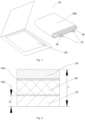
Fig. 1 is a view of the package of the battery according to an embodiment of the present application; -
Fig. 2 is a section view of the package film according to an embodiment of the present application; -
Fig. 3 is a front view of the electrode tab assembly according to an embodiment of the present application; -
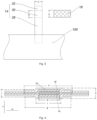
Fig. 4 is a partial section view of the battery element according to an embodiment of the present application; -
Fig. 5 is a section view of the single-layered electrode tab assembly according to an embodiment of the present application; -
Fig. 6 is a section view of multi-layers of single-layered electrode tab assembly according to an embodiment of the present application; and -
Fig. 7 is a partial front view of the battery element according to an embodiment of the present application. - The present application will now be described with reference to
Fig. 1 to Fig.7 . It is to be understood that the various embodiments shown in the following figures and the examples described below are exemplary embodiments of the present application and are not intended to limit the present invention. Various embodiments may be combined with one another to form other examples not shown in the figures. - As shown in
Fig. 1 , according to an embodiment of the present application, abattery 10 is provided. Specifically, thebattery 10 may be broadly described as including abattery element 100, anelectrode tab assembly 12, and apackage film 20. Among them, thebattery element 100 includes a positive electrode, a negative electrode, a separator, and an electrolyte. The positive electrode includes a positive current collector and a positive active substance layer coated on the surface of the positive current collector. The negative electrode includes a negative current collector and a negative active substance layer coated on the surface of the negative current collector. - With further reference to
Figs. 1 to 3 , theelectrode tab assembly 12 includes anelectrode tab 14 and aprotective layer 16 arranged on theelectrode tab 14. Theprotective layer 16 includes a first connectinglayer 18, and the first connectinglayer 18 is arranged outside theprotective layer 16. Thepackage film 20 includes a second connectinglayer 22 arranged outside the first connectinglayer 18. After theelectrode tab assembly 12 is packaged, the outside of thepackage film 20 forms a first step and a second step, as shown inFig. 4 . - It is understood that the
package film 20 is used to package thebattery element 100 and theelectrode tab assembly 12, that is, thebattery element 100 is packaged using thepackage film 20. The general process is: stamping thepackage film 20, punching out a slot of electrode assembly; placing an electrode assembly into the slot of electrode assembly, and then performing the package as shown inFig. 1 . - With reference to
Fig. 2 , in an embodiment of the present application, thepackage film 20 further includes a firstorganic layer 24, and afirst metal layer 26 arranged between the firstorganic layer 24 and the second connecting layer 22in the thickness direction of thepackage film 20. In an alternative embodiment, a firstadhesive layer 102 may be arranged between thefirst metal layer 26 and the second connectinglayer 22, and a secondadhesive layer 104 may be arranged between the firstorganic layer 24 and thefirst metal layer 26. Further, thepackage film 20 may also have a matte layer outside the firstorganic layer 24. - With further reference to
Fig. 3 , in an embodiment of the present application, theelectrode tab 14 includes, in order, afirst region 28 connected to thebattery element 100, asecond region 30 in which aboveprotective layer 16 is arranged and athird region 32, in the length direction of theelectrode tab 14. Among them, the width of theelectrode tab 14 is y and the width of theprotective layer 16 is x. It is understood that thefirst region 28 may form a connection region connected with thebattery element 100, and thethird region 32 may be formed as a head empty foil region of theelectrode tab 14. - Now see
Figs. 4 through 7 . In the first direction T of the battery 10 (e.g, in the thickness direction of thebattery 10 in the illustrated embodiment), the first step has a first thickness h and the second step has a second thickness j. Among them, the first thickness h and the second thickness j respectively satisfy the following formula:

- Specifically, t is the thickness of the
package film 20, a is the thickness of the second connectinglayer 22, p is the thickness of theelectrode tab assembly 12, c is the thickness of the first connectinglayer 18, and b is the thickness of theelectrode tab 14.
wherein, in the above formula of the present application, the units of the respective thicknesses are the same. - As stated above, in the
battery 10 provided by the present application, after theelectrode tab assembly 12 is packaged, a first step and a second step may be formed outside thepackage film 20. By forming the first step and the second step with a first thickness h and a second thickness j in the first direction T of thebattery 10, and by defining above thicknesses to be in the range of 2t+p-(2c+2a)×95%<h<2t+p-(2c+2a)×5% and 2t+p-b-(2c+2a)×95%<j<2t+p-b-(2c+2a)×5% respectively, the sealing strength of the battery may be ensured to be higher without liquid leakage. - With further reference to
Fig. 4 , the first step and the second step have a first width i and a second width g in a second direction W of the battery 10 (e.g, in the width direction of thebattery 10 in the illustrated embodiment), wherein the first width i and the second width g satisfy:
- Specifically, k is the width of the
protective layer 16, and w is the width of theelectrode tab 14. - According to the present invention, as shown in
Fig. 4 , the second step is formed on both sides of the first step in the second direction W of thebattery 10, and wherein the first thickness h is greater than the second thickness j. - As shown, in an embodiment of the present application, the sum of the thickness of the second connecting
layer 22 and the thickness c of the first connectinglayer 18 is f, f = a + c. In the present application, when theelectrode tab 12 is packaged, the thermal compression ratio of the second connectinglayer 22 and the first connectinglayer 18 is 5% to 95%, so that a better melting effect may be achieved to ensure a high strength and no leakage and penetration. If the thermal compression ratio is less than 5%, the connection area may be too thin and there is a risk of short circuit; if the thermal compression ratio is greater than 95%, the package is too thick, the strength of the hot press is insufficient, and there is a risk of leakage or moisture penetration. - According to an embodiment of the present application, the first connecting
layer 18 forms the outermost layer of theprotective layer 16. The resin layer outside theelectrode tab assembly 12 is a single layer, and its cross-sectional structural view in the thickness direction of theelectrode tab assembly 12 is shown inFig. 5 ; the resin layer outside theelectrode tab assembly 12 is a multilayer, and the outermost layer is the first connectinglayer 18, and its cross-sectional structural view in the thickness direction of theelectrode tab assembly 12 is shown inFig. 6 . When the resin layer outside theelectrode tab assembly 12 is a multilayer structure, the melting points of the materials of the different layers are different, and the outermost layer is a resin layer having a melt heat sealing effect. Preferably, the inner layer may be made of the material with a high melting point to enhance the insulating effect, thus avoiding over-melting of the first connectinglayer 18 which may cause theelectrode tab 14 and thefirst metal layer 26 of thepackage film 20 to conduct to form electrochemical corrosion. - In addition, in an alternative embodiment of the present application, the width of the portion of the
protective layer 16 exposed by thepackage film 20 may be greater than 0.05 mm in the length of theelectrode tab 14. Alternatively, the minimum distance between thefirst metal layer 26 and theelectrode tab 14 may be greater than 15 µm in the first direction T of thebattery 10. - Further, according to an alternative embodiment of the present application, the first connecting
layer 18 has a melting point of MP1, and the second connectinglayer 22 has a melting point of MP2, wherein |MP1 - MP2 | ≤ 30 °C. Thus, the sealing effect may be further improved. If the difference in melting points between the first connectinglayer 18 and the second connectinglayer 22 is too large, the heat sealing and melting effect is poor, the strength is low, and there is a risk of leakage and moisture permeation. - According to an alternative embodiment of the present application, the second connecting
layer 22 may contain random polypropylene resin or chlorinated polypropylene resin, thefirst metal layer 26 may contain aluminum or stainless steel, the firstorganic layer 24 may contain nylon or polyethylene terephthalate, and the first connectinglayer 18 may contain polypropylene or polyethylene. - According to an embodiment of the present application, as shown in
Fig. 7 , the width x of theprotective layer 16 is greater than the width d of a sealingportion 40 of thebattery element 100 in the length direction of theelectrode tab 14. If the width of the sealingportion 40 is too small, the sealing effect is poor, and if the width of the sealingportion 40 is too large, the battery energy density may be lowered. If the width of the sealingportion 40 exceeds the width of theprotective layer 16, there may be a risk of corrosion and leakage. - According to an embodiment of the present application, in order to avoid the
first metal layer 26 directly contacting theelectrode tab 14, the width e of the portion of theprotective layer 16 exposed by thepackage film 20 is greater than 0.1 mm in the length direction of theelectrode tab 14. - According to an embodiment of the present application, the minimum distance between the
first metal layer 26 and theelectrode tab 14 is greater than 15 µm in the thickness direction of the sealingportion 40. That is, the distance at any position between thefirst metal layer 26 and theelectrode tab 14 is greater than 15 µm. Thereby, it is further ensured that theelectrode tab 14 of theelectrode tab assembly 12 has a certain insulation distance from thefirst metal layer 26 in the package film, thus avoiding electrochemical corrosion and short circuit. - In the preparation process of the present application, the positive active substance layer contains a positive active material, and the positive active material may be one selected from a group consisting of lithium cobaltate, lithium manganate, nickel cobalt aluminum ternary material (NCA) and nickel cobalt manganese ternary material (NCM); the negative active substance layer contains a negative active material, and the negative active material may be one selected from a group consisting of graphite and a Si-containing material.
- The electrolyte may be selected from solid, liquid, and gel electrolytes.
- When a liquid electrolyte or a gel state electrolyte is used, the
battery element 100 further contains a separator, and the separator is selected from a polyolefin separator. - Specifically, the positive electrode may be prepared as follows:
The positive electrode includes a positive current collector and a positive active material layer coated on the surface of the current collector. The positive current collector is made of a metal foil, and aluminum foil is commonly used. The positive active material layer includes a positive active substance, a binder, and a conductive agent. The positive active substance may be a composite oxide composed of a transition metal such as lithium cobaltate, lithium iron phosphate, nickel cobalt manganese or nickel cobalt aluminum or lithium manganate. The conductive agent may be a conductive material such as carbon black, carbon nanotubes, carbon fibers, graphene, or conductive graphite. The binder may be polytetrafluoroethylene or poly(vinylidene fluoride). The solvent may be N-methylpyrrolidone (NMP). The following example exemplifies a certain ratio of the positive material, and is not limited to the mixing ratio. - Preparing a positive slurry contains97% lithium cobaltate: 1.8% conductive carbon black: 1.2% binder of polyvinylidene fluoride. The lithium cobaltate and the conductive agent are firstly mixed uniformly, and the solvent NMP is added to uniformly disperse and the binder is added to adjust the viscosityto obtain a positive slurry. The positive slurry is uniformly coated on the surface of the current collector, followed by drying at a high temperature to remove the solvent, and rolling to form a compacted positive electrode.
- The negative electrode may be prepared as follows:
The negative electrode includes a negative current collector and a negative active material layer coated on the surface of the current collector. The negative current collector is made of a metal foil, and copper foil is commonly used. The negative active material layer includes a negative active substance, a binder, and a conductive agent. The negative active substance may be graphite or a carbon-containing composite or a metal material such as artificial graphite, natural graphite, mesocarbon microbeads, carbon fiber, hard carbon, silicon carbon negative electrode, lithium negative electrode, and the like. The conductive agent may be a conductive material such as carbon black, carbon nanotubes, carbon fibers, graphene, or conductive graphite. The binder may be styrene-butadiene rubber or poly(vinylidene fluoride). If necessary, a thickener such as sodium carboxymethylcellulose (CMC) may be added to make the negative slurry more stable. The solvent may be N-methylpyrrolidone (NMP) or deionized water. The negative material of one of the ratios is exemplified below, and is not limited to the mixing ratio, and the solvent is deionized water. Preparing a negative slurry contains96.5% artificial graphite: 1% conductive carbon black: 1.5% styrene butadiene rubber: 1% CMC. The graphite and the conductive carbon black are firstly mixed uniformly, and the solvent of deionized water and CMC is added to uniformly disperse, and the binder of styrene-butadiene rubber is added to adjust the viscosity, to obtain a negative slurry. The negative slurry is uniformly coated on the surface of the current collector, followed by drying at a high temperature to remove the solvent, and rolling to form a compacted negative electrode. - The electrolyte may be prepared as follows:
The electrolyte includes an electrolyte salt and an organic solvent, and a gel electrolyte may also be used. - The organic solvents that can be used as the electrolyte may be: diethyl carbonate, dimethyl carbonate, ethyl methyl carbonate, dipropyl carbonate, ethyl propyl carbonate, propylene carbonate, ethylene carbonate, propylene carbonate, ethyl propionate, propyl propionate, propylene sulfite, and the like. The electrolyte salt may be, for example, LiPF6, LiBF4, or the like.
- In this embodiment, an electrolyte having a solvent ratio of 50% of propionic acid propionate, 25% of ethylene carbonate, 16% of propylene carbonate, 6% of ethanedinitrile, 3% of ethylene carbonate, and a lithium salt LiPF6 with a concentration of 1.1 mol/L is used.
- A porous polyethylene film having a thickness of 8 um and a porosity of 30% is used.
- The positive and negative electrodes are cut to make the negative electrode 2 mm wider than the positive electrode, and the negative electrode tab is taken out at the empty current collector of the negative electrode, and the positive electrode tab is taken out at the empty current collector of the positive electrode. And the width of the separator is 2.5 mm wider than the negative electrode to ensure that there is a separator between the positive and negative electrodes for insulation, the opposite side of the positive active material layer is wrapped by the negative active material layer, and the separator exceeds both ends of the negative electrode. Then the positive and negative electrodes and the separator are wound to obtain the
battery element 100. - As shown in
Fig. 1 , after the battery element is placed in a package bag for top-sealing, the electrolyte is injected to complete the package, and after the formation, the gas is extracted and the opening is sealed to form the battery. - According to an embodiment of the present application, a device is provided. The device includes a package, and the
battery 10 is received in the package.
Claims (9)
- A battery, comprising:an electrode tab assembly, comprising:an electrode tab, anda protective layer arranged on the electrode tab and comprising a first connecting layer being an outermost layer of the protective layer;a package film comprising multiple layers of which one is a second connecting layer arranged on a surface of the first connecting layer, characterized in that, after the electrode tab assembly is packaged, a first step and a second step are formed on an outer surface of the package film; and the first step and the second step have a first thickness h and a second thickness j in a first direction of the battery respectively, and the second step is formed on both sides of the first step along a second direction of the battery, wherein the first direction is in the thickness direction of the battery and the second direction is in the width direction of the battery, and the first thickness h and the second thickness j respectively satisfying the following formulas:


 wherein t is a thickness of the package film, a is a thickness of the second connecting layer, p is a thickness of the electrode tab assembly, c is a thickness of the first connecting layer, and b is a thickness of the electrode tab;and the first thickness h and the second thickness j both comprising a thickness of the first connecting layer and a thickness of the second connecting layer in the first direction of the battery.
 - The battery according to claim 1, characterized in that the first step and the second step have a first width i and a second width g along a second direction of the battery respectively, wherein the first width i and the second width g satisfy:

- The battery according to claim 1, characterized in that the package film further comprises a first organic layer and a first metal layer arranged between the first organic layer and the second connecting layer along the thickness direction of the package film.
- The battery according to claim 1, characterized in that further comprising a battery element; wherein the electrode tab comprises, in order, a first region connected to the battery element, a second region in which the protective layer is arranged, and a third region along the length direction of the electrode tab.
- The battery according to claim 1, characterized in that the width of a portion of the protective layer exposed by the package film is greater than 0.05 mm along the length direction of the electrode tab.
- The battery according to claim 1, characterized in that the first connecting layer has a melting point of MP1, and the second connecting layer has a melting point of MP2, wherein |MP1 - MP2 | ≤ 30 °C.
- The battery according to claim 3, characterized in that a minimum distance between the first metal layer and the electrode tab is greater than 15 µm along the first direction of the battery.
- The battery according to claim 3, characterized in that the second connecting layer contains random polypropylene resin or chlorinated polypropylene resin, the first metal layer contains aluminum or stainless steel, the first organic layer contains nylon or polyethylene terephthalate, and the first connecting layer contains polypropylene or polyethylene.
- A device comprising a package and a battery received in the package, the battery according to any preceding claims.
Applications Claiming Priority (2)
| Application Number | Priority Date | Filing Date | Title |
|---|---|---|---|
| CN201820510649.1U CN208000939U (en) | 2018-04-11 | 2018-04-11 | Battery and equipment |
| US16/203,601 US11177541B2 (en) | 2018-04-11 | 2018-11-28 | Battery and device |
Publications (2)
| Publication Number | Publication Date |
|---|---|
| EP3660940A1 EP3660940A1 (en) | 2020-06-03 |
| EP3660940B1 true EP3660940B1 (en) | 2024-07-03 |
Family
ID=63840405
Family Applications (1)
| Application Number | Title | Priority Date | Filing Date |
|---|---|---|---|
| EP19176841.5A Active EP3660940B1 (en) | 2018-04-11 | 2019-05-27 | Battery and device |
Country Status (3)
| Country | Link |
|---|---|
| US (1) | US11177541B2 (en) |
| EP (1) | EP3660940B1 (en) |
| CN (1) | CN208000939U (en) |
Families Citing this family (7)
| Publication number | Priority date | Publication date | Assignee | Title |
|---|---|---|---|---|
| CN109713207B (en) * | 2019-01-31 | 2024-07-09 | 柔电(武汉)科技有限公司 | A flexible battery with optimized tab and a tab optimization process |
| KR102913522B1 (en) * | 2020-03-24 | 2026-01-16 | 동관 파워앰프 테크놀로지 리미티드 | Electrochemical devices and electronic devices |
| CN114379171A (en) * | 2020-10-21 | 2022-04-22 | 宁德新能源科技有限公司 | Packaging film, battery and electronic device |
| CN113097617A (en) * | 2021-03-30 | 2021-07-09 | 宁德新能源科技有限公司 | Electrochemical device and electronic device |
| WO2023055052A1 (en) * | 2021-09-28 | 2023-04-06 | 주식회사 엘지에너지솔루션 | Battery cell, battery module, and method for manufacturing battery cell |
| CN114552144B (en) * | 2022-01-26 | 2024-03-08 | 北京恩力动力科技有限公司 | Negative electrode, secondary battery and preparation method of negative electrode |
| CN120149649B (en) * | 2025-03-14 | 2025-12-02 | 蜂巢能源科技股份有限公司 | Batteries and battery packs |
Family Cites Families (11)
| Publication number | Priority date | Publication date | Assignee | Title |
|---|---|---|---|---|
| US6379840B2 (en) * | 1998-03-18 | 2002-04-30 | Ngk Insulators, Ltd. | Lithium secondary battery |
| US6403262B1 (en) * | 2000-02-10 | 2002-06-11 | Ntk Powerdex, Inc. | Li-Ion cell with shielded leads |
| JP2002190283A (en) * | 2000-12-21 | 2002-07-05 | At Battery:Kk | Method of manufacturing thin secondary battery and thin secondary battery |
| JP5082263B2 (en) * | 2006-03-10 | 2012-11-28 | 日本電気株式会社 | Method for manufacturing film-covered electrical device |
| CN107369785B (en) * | 2011-08-29 | 2020-11-17 | 村田新能源(无锡)有限公司 | Battery pack, method for manufacturing battery pack, battery, and electronic device |
| JP5909985B2 (en) * | 2011-10-17 | 2016-04-27 | ソニー株式会社 | Battery, battery manufacturing method, battery pack, electronic device, electric vehicle, power storage device, and power system |
| CN104145350B (en) * | 2012-02-29 | 2017-07-21 | 日新制钢株式会社 | The manufacture method of the outer casing member of Stackable batteries, the manufacture method of the outer casing member of Stackable batteries and Stackable batteries |
| TWI553941B (en) * | 2013-10-29 | 2016-10-11 | Lg化學股份有限公司 | Gel polymer electrolyte and lithium secondary battery comprising the same |
| KR101984265B1 (en) * | 2015-07-03 | 2019-05-30 | 주식회사 엘지화학 | Pouch type secondary battery and method of fabricating the same |
| KR101904587B1 (en) * | 2015-09-01 | 2018-10-04 | 주식회사 엘지화학 | Battery cell and method for manufacturing the same |
| CN106784998B (en) * | 2017-01-22 | 2024-10-15 | 宁德新能源科技有限公司 | Secondary battery and heating device |
-
2018
- 2018-04-11 CN CN201820510649.1U patent/CN208000939U/en active Active
- 2018-11-28 US US16/203,601 patent/US11177541B2/en active Active
-
2019
- 2019-05-27 EP EP19176841.5A patent/EP3660940B1/en active Active
Also Published As
| Publication number | Publication date |
|---|---|
| CN208000939U (en) | 2018-10-23 |
| US11177541B2 (en) | 2021-11-16 |
| EP3660940A1 (en) | 2020-06-03 |
| US20190319251A1 (en) | 2019-10-17 |
Similar Documents
| Publication | Publication Date | Title |
|---|---|---|
| EP3660940B1 (en) | Battery and device | |
| CN100472845C (en) | Battery | |
| EP0975041B1 (en) | Flat cells | |
| JP5591569B2 (en) | Square battery, method for manufacturing the same, and assembled battery using the same | |
| EP0954042B1 (en) | Lithium ion secondary battery and manufacture thereof | |
| CN1805204B (en) | Non-aqueous electrolyte battery | |
| CN106784998B (en) | Secondary battery and heating device | |
| US6617074B1 (en) | Lithium ion polymer secondary battery and gelatinous polymer electrolyte for sheet battery | |
| US20160043373A1 (en) | Lithium-ion secondary cell and method for manufacturing same | |
| EP1041658A1 (en) | Method for producing nonaqueous gel electrolyte cell | |
| EP0851521A2 (en) | Lithium ion secondary battery | |
| JPH10177865A (en) | Lithium ion secondary battery and method of manufacturing the same | |
| CN102842735A (en) | Non-aqueous secondary battery and manufacturing method thereof | |
| CN102856578A (en) | Non-aqueous secondary battery | |
| CN206480713U (en) | A kind of secondary cell and heater | |
| KR102656799B1 (en) | Battery internal short circuit inductive device, battery having the same, and battery internal short circuit safety evaluating method | |
| KR20100101626A (en) | Battery | |
| JP2007103356A (en) | Non-aqueous secondary battery | |
| KR101495953B1 (en) | Pouch for secondary battery and secondary battery using the same | |
| JP2002245988A (en) | Thin battery | |
| JPWO2020009206A1 (en) | Coin-type battery and its manufacturing method | |
| JP4316951B2 (en) | Electrode and lithium ion secondary battery | |
| JP2010244725A (en) | Non-aqueous electrolyte battery | |
| JP2007095465A (en) | Sealed battery and manufacturing method thereof | |
| JP3869668B2 (en) | Electrochemical device and manufacturing method thereof |
Legal Events
| Date | Code | Title | Description |
|---|---|---|---|
| PUAI | Public reference made under article 153(3) epc to a published international application that has entered the european phase |
Free format text: ORIGINAL CODE: 0009012 |
|
| STAA | Information on the status of an ep patent application or granted ep patent |
Free format text: STATUS: THE APPLICATION HAS BEEN PUBLISHED |
|
| AK | Designated contracting states |
Kind code of ref document: A1 Designated state(s): AL AT BE BG CH CY CZ DE DK EE ES FI FR GB GR HR HU IE IS IT LI LT LU LV MC MK MT NL NO PL PT RO RS SE SI SK SM TR |
|
| AX | Request for extension of the european patent |
Extension state: BA ME |
|
| STAA | Information on the status of an ep patent application or granted ep patent |
Free format text: STATUS: REQUEST FOR EXAMINATION WAS MADE |
|
| 17P | Request for examination filed |
Effective date: 20201203 |
|
| RBV | Designated contracting states (corrected) |
Designated state(s): AL AT BE BG CH CY CZ DE DK EE ES FI FR GB GR HR HU IE IS IT LI LT LU LV MC MK MT NL NO PL PT RO RS SE SI SK SM TR |
|
| STAA | Information on the status of an ep patent application or granted ep patent |
Free format text: STATUS: EXAMINATION IS IN PROGRESS |
|
| 17Q | First examination report despatched |
Effective date: 20230829 |
|
| REG | Reference to a national code |
Ref legal event code: R079 Ipc: H01M0050119000 Ref country code: DE Ref document number: 602019054466 Country of ref document: DE Free format text: PREVIOUS MAIN CLASS: H01M0002020000 |
|
| GRAP | Despatch of communication of intention to grant a patent |
Free format text: ORIGINAL CODE: EPIDOSNIGR1 |
|
| STAA | Information on the status of an ep patent application or granted ep patent |
Free format text: STATUS: GRANT OF PATENT IS INTENDED |
|
| RIC1 | Information provided on ipc code assigned before grant |
Ipc: H01M 50/557 20210101ALN20240111BHEP Ipc: H01M 50/553 20210101ALN20240111BHEP Ipc: H01M 50/55 20210101ALN20240111BHEP Ipc: H01M 50/538 20210101ALN20240111BHEP Ipc: H01M 50/197 20210101ALN20240111BHEP Ipc: H01M 50/176 20210101ALN20240111BHEP Ipc: H01M 50/193 20210101ALN20240111BHEP Ipc: H01M 50/129 20210101ALI20240111BHEP Ipc: H01M 50/121 20210101ALI20240111BHEP Ipc: H01M 50/119 20210101AFI20240111BHEP |
|
| INTG | Intention to grant announced |
Effective date: 20240125 |
|
| GRAS | Grant fee paid |
Free format text: ORIGINAL CODE: EPIDOSNIGR3 |
|
| GRAA | (expected) grant |
Free format text: ORIGINAL CODE: 0009210 |
|
| STAA | Information on the status of an ep patent application or granted ep patent |
Free format text: STATUS: THE PATENT HAS BEEN GRANTED |
|
| P01 | Opt-out of the competence of the unified patent court (upc) registered |
Effective date: 20240522 |
|
| AK | Designated contracting states |
Kind code of ref document: B1 Designated state(s): AL AT BE BG CH CY CZ DE DK EE ES FI FR GB GR HR HU IE IS IT LI LT LU LV MC MK MT NL NO PL PT RO RS SE SI SK SM TR |
|
| RAP3 | Party data changed (applicant data changed or rights of an application transferred) |
Owner name: NINGDE AMPEREX TECHNOLOGY LIMITED |
|
| REG | Reference to a national code |
Ref country code: CH Ref legal event code: EP |
|
| REG | Reference to a national code |
Ref country code: DE Ref legal event code: R096 Ref document number: 602019054466 Country of ref document: DE |
|
| REG | Reference to a national code |
Ref country code: NL Ref legal event code: FP |
|
| REG | Reference to a national code |
Ref country code: LT Ref legal event code: MG9D |
|
| PG25 | Lapsed in a contracting state [announced via postgrant information from national office to epo] |
Ref country code: PT Free format text: LAPSE BECAUSE OF FAILURE TO SUBMIT A TRANSLATION OF THE DESCRIPTION OR TO PAY THE FEE WITHIN THE PRESCRIBED TIME-LIMIT Effective date: 20241104 |
|
| REG | Reference to a national code |
Ref country code: AT Ref legal event code: MK05 Ref document number: 1700791 Country of ref document: AT Kind code of ref document: T Effective date: 20240703 |
|
| PG25 | Lapsed in a contracting state [announced via postgrant information from national office to epo] |
Ref country code: PT Free format text: LAPSE BECAUSE OF FAILURE TO SUBMIT A TRANSLATION OF THE DESCRIPTION OR TO PAY THE FEE WITHIN THE PRESCRIBED TIME-LIMIT Effective date: 20241104 |
|
| PG25 | Lapsed in a contracting state [announced via postgrant information from national office to epo] |
Ref country code: NO Free format text: LAPSE BECAUSE OF FAILURE TO SUBMIT A TRANSLATION OF THE DESCRIPTION OR TO PAY THE FEE WITHIN THE PRESCRIBED TIME-LIMIT Effective date: 20241003 |
|
| PG25 | Lapsed in a contracting state [announced via postgrant information from national office to epo] |
Ref country code: GR Free format text: LAPSE BECAUSE OF FAILURE TO SUBMIT A TRANSLATION OF THE DESCRIPTION OR TO PAY THE FEE WITHIN THE PRESCRIBED TIME-LIMIT Effective date: 20241004 Ref country code: FI Free format text: LAPSE BECAUSE OF FAILURE TO SUBMIT A TRANSLATION OF THE DESCRIPTION OR TO PAY THE FEE WITHIN THE PRESCRIBED TIME-LIMIT Effective date: 20240703 Ref country code: PL Free format text: LAPSE BECAUSE OF FAILURE TO SUBMIT A TRANSLATION OF THE DESCRIPTION OR TO PAY THE FEE WITHIN THE PRESCRIBED TIME-LIMIT Effective date: 20240703 |
|
| PG25 | Lapsed in a contracting state [announced via postgrant information from national office to epo] |
Ref country code: BG Free format text: LAPSE BECAUSE OF FAILURE TO SUBMIT A TRANSLATION OF THE DESCRIPTION OR TO PAY THE FEE WITHIN THE PRESCRIBED TIME-LIMIT Effective date: 20240703 |
|
| PG25 | Lapsed in a contracting state [announced via postgrant information from national office to epo] |
Ref country code: LV Free format text: LAPSE BECAUSE OF FAILURE TO SUBMIT A TRANSLATION OF THE DESCRIPTION OR TO PAY THE FEE WITHIN THE PRESCRIBED TIME-LIMIT Effective date: 20240703 |
|
| PG25 | Lapsed in a contracting state [announced via postgrant information from national office to epo] |
Ref country code: IS Free format text: LAPSE BECAUSE OF FAILURE TO SUBMIT A TRANSLATION OF THE DESCRIPTION OR TO PAY THE FEE WITHIN THE PRESCRIBED TIME-LIMIT Effective date: 20241103 Ref country code: AT Free format text: LAPSE BECAUSE OF FAILURE TO SUBMIT A TRANSLATION OF THE DESCRIPTION OR TO PAY THE FEE WITHIN THE PRESCRIBED TIME-LIMIT Effective date: 20240703 |
|
| PG25 | Lapsed in a contracting state [announced via postgrant information from national office to epo] |
Ref country code: CZ Free format text: LAPSE BECAUSE OF FAILURE TO SUBMIT A TRANSLATION OF THE DESCRIPTION OR TO PAY THE FEE WITHIN THE PRESCRIBED TIME-LIMIT Effective date: 20240703 Ref country code: HR Free format text: LAPSE BECAUSE OF FAILURE TO SUBMIT A TRANSLATION OF THE DESCRIPTION OR TO PAY THE FEE WITHIN THE PRESCRIBED TIME-LIMIT Effective date: 20240703 |
|
| PG25 | Lapsed in a contracting state [announced via postgrant information from national office to epo] |
Ref country code: RS Free format text: LAPSE BECAUSE OF FAILURE TO SUBMIT A TRANSLATION OF THE DESCRIPTION OR TO PAY THE FEE WITHIN THE PRESCRIBED TIME-LIMIT Effective date: 20241003 Ref country code: ES Free format text: LAPSE BECAUSE OF FAILURE TO SUBMIT A TRANSLATION OF THE DESCRIPTION OR TO PAY THE FEE WITHIN THE PRESCRIBED TIME-LIMIT Effective date: 20240703 |
|
| PG25 | Lapsed in a contracting state [announced via postgrant information from national office to epo] |
Ref country code: RS Free format text: LAPSE BECAUSE OF FAILURE TO SUBMIT A TRANSLATION OF THE DESCRIPTION OR TO PAY THE FEE WITHIN THE PRESCRIBED TIME-LIMIT Effective date: 20241003 Ref country code: PL Free format text: LAPSE BECAUSE OF FAILURE TO SUBMIT A TRANSLATION OF THE DESCRIPTION OR TO PAY THE FEE WITHIN THE PRESCRIBED TIME-LIMIT Effective date: 20240703 Ref country code: NO Free format text: LAPSE BECAUSE OF FAILURE TO SUBMIT A TRANSLATION OF THE DESCRIPTION OR TO PAY THE FEE WITHIN THE PRESCRIBED TIME-LIMIT Effective date: 20241003 Ref country code: LV Free format text: LAPSE BECAUSE OF FAILURE TO SUBMIT A TRANSLATION OF THE DESCRIPTION OR TO PAY THE FEE WITHIN THE PRESCRIBED TIME-LIMIT Effective date: 20240703 Ref country code: IS Free format text: LAPSE BECAUSE OF FAILURE TO SUBMIT A TRANSLATION OF THE DESCRIPTION OR TO PAY THE FEE WITHIN THE PRESCRIBED TIME-LIMIT Effective date: 20241103 Ref country code: HR Free format text: LAPSE BECAUSE OF FAILURE TO SUBMIT A TRANSLATION OF THE DESCRIPTION OR TO PAY THE FEE WITHIN THE PRESCRIBED TIME-LIMIT Effective date: 20240703 Ref country code: GR Free format text: LAPSE BECAUSE OF FAILURE TO SUBMIT A TRANSLATION OF THE DESCRIPTION OR TO PAY THE FEE WITHIN THE PRESCRIBED TIME-LIMIT Effective date: 20241004 Ref country code: FI Free format text: LAPSE BECAUSE OF FAILURE TO SUBMIT A TRANSLATION OF THE DESCRIPTION OR TO PAY THE FEE WITHIN THE PRESCRIBED TIME-LIMIT Effective date: 20240703 Ref country code: ES Free format text: LAPSE BECAUSE OF FAILURE TO SUBMIT A TRANSLATION OF THE DESCRIPTION OR TO PAY THE FEE WITHIN THE PRESCRIBED TIME-LIMIT Effective date: 20240703 Ref country code: CZ Free format text: LAPSE BECAUSE OF FAILURE TO SUBMIT A TRANSLATION OF THE DESCRIPTION OR TO PAY THE FEE WITHIN THE PRESCRIBED TIME-LIMIT Effective date: 20240703 Ref country code: BG Free format text: LAPSE BECAUSE OF FAILURE TO SUBMIT A TRANSLATION OF THE DESCRIPTION OR TO PAY THE FEE WITHIN THE PRESCRIBED TIME-LIMIT Effective date: 20240703 Ref country code: AT Free format text: LAPSE BECAUSE OF FAILURE TO SUBMIT A TRANSLATION OF THE DESCRIPTION OR TO PAY THE FEE WITHIN THE PRESCRIBED TIME-LIMIT Effective date: 20240703 |
|
| REG | Reference to a national code |
Ref country code: DE Ref legal event code: R097 Ref document number: 602019054466 Country of ref document: DE |
|
| PG25 | Lapsed in a contracting state [announced via postgrant information from national office to epo] |
Ref country code: RO Free format text: LAPSE BECAUSE OF FAILURE TO SUBMIT A TRANSLATION OF THE DESCRIPTION OR TO PAY THE FEE WITHIN THE PRESCRIBED TIME-LIMIT Effective date: 20240703 Ref country code: SM Free format text: LAPSE BECAUSE OF FAILURE TO SUBMIT A TRANSLATION OF THE DESCRIPTION OR TO PAY THE FEE WITHIN THE PRESCRIBED TIME-LIMIT Effective date: 20240703 Ref country code: DK Free format text: LAPSE BECAUSE OF FAILURE TO SUBMIT A TRANSLATION OF THE DESCRIPTION OR TO PAY THE FEE WITHIN THE PRESCRIBED TIME-LIMIT Effective date: 20240703 |
|
| PG25 | Lapsed in a contracting state [announced via postgrant information from national office to epo] |
Ref country code: EE Free format text: LAPSE BECAUSE OF FAILURE TO SUBMIT A TRANSLATION OF THE DESCRIPTION OR TO PAY THE FEE WITHIN THE PRESCRIBED TIME-LIMIT Effective date: 20240703 |
|
| PG25 | Lapsed in a contracting state [announced via postgrant information from national office to epo] |
Ref country code: IT Free format text: LAPSE BECAUSE OF FAILURE TO SUBMIT A TRANSLATION OF THE DESCRIPTION OR TO PAY THE FEE WITHIN THE PRESCRIBED TIME-LIMIT Effective date: 20240703 Ref country code: SK Free format text: LAPSE BECAUSE OF FAILURE TO SUBMIT A TRANSLATION OF THE DESCRIPTION OR TO PAY THE FEE WITHIN THE PRESCRIBED TIME-LIMIT Effective date: 20240703 |
|
| PLBE | No opposition filed within time limit |
Free format text: ORIGINAL CODE: 0009261 |
|
| STAA | Information on the status of an ep patent application or granted ep patent |
Free format text: STATUS: NO OPPOSITION FILED WITHIN TIME LIMIT |
|
| PGFP | Annual fee paid to national office [announced via postgrant information from national office to epo] |
Ref country code: NL Payment date: 20250409 Year of fee payment: 7 |
|
| 26N | No opposition filed |
Effective date: 20250404 |
|
| PGFP | Annual fee paid to national office [announced via postgrant information from national office to epo] |
Ref country code: DE Payment date: 20250402 Year of fee payment: 7 |
|
| PGFP | Annual fee paid to national office [announced via postgrant information from national office to epo] |
Ref country code: FR Payment date: 20250401 Year of fee payment: 7 |
|
| PG25 | Lapsed in a contracting state [announced via postgrant information from national office to epo] |
Ref country code: SE Free format text: LAPSE BECAUSE OF FAILURE TO SUBMIT A TRANSLATION OF THE DESCRIPTION OR TO PAY THE FEE WITHIN THE PRESCRIBED TIME-LIMIT Effective date: 20240703 |
|
| REG | Reference to a national code |
Ref country code: CH Ref legal event code: H13 Free format text: ST27 STATUS EVENT CODE: U-0-0-H10-H13 (AS PROVIDED BY THE NATIONAL OFFICE) Effective date: 20251223 |
|
| PG25 | Lapsed in a contracting state [announced via postgrant information from national office to epo] |
Ref country code: LU Free format text: LAPSE BECAUSE OF NON-PAYMENT OF DUE FEES Effective date: 20250527 |
|
| PG25 | Lapsed in a contracting state [announced via postgrant information from national office to epo] |
Ref country code: CH Free format text: LAPSE BECAUSE OF NON-PAYMENT OF DUE FEES Effective date: 20250531 |
|
| REG | Reference to a national code |
Ref country code: BE Ref legal event code: MM Effective date: 20250531 |
|
| PG25 | Lapsed in a contracting state [announced via postgrant information from national office to epo] |
Ref country code: MC Free format text: LAPSE BECAUSE OF FAILURE TO SUBMIT A TRANSLATION OF THE DESCRIPTION OR TO PAY THE FEE WITHIN THE PRESCRIBED TIME-LIMIT Effective date: 20240703 |
|
| PGFP | Annual fee paid to national office [announced via postgrant information from national office to epo] |
Ref country code: GB Payment date: 20260324 Year of fee payment: 8 |
|
| PG25 | Lapsed in a contracting state [announced via postgrant information from national office to epo] |
Ref country code: IE Free format text: LAPSE BECAUSE OF NON-PAYMENT OF DUE FEES Effective date: 20250527 |
|
| PG25 | Lapsed in a contracting state [announced via postgrant information from national office to epo] |
Ref country code: BE Free format text: LAPSE BECAUSE OF NON-PAYMENT OF DUE FEES Effective date: 20250531 |