EP3660803A1 - Cushioned remote control unit for a vehicle and system comprising both the control unit and the vehicle - Google Patents
Cushioned remote control unit for a vehicle and system comprising both the control unit and the vehicle Download PDFInfo
- Publication number
- EP3660803A1 EP3660803A1 EP18209449.0A EP18209449A EP3660803A1 EP 3660803 A1 EP3660803 A1 EP 3660803A1 EP 18209449 A EP18209449 A EP 18209449A EP 3660803 A1 EP3660803 A1 EP 3660803A1
- Authority
- EP
- European Patent Office
- Prior art keywords
- remote control
- control unit
- unit
- electronic circuit
- signal
- Prior art date
- Legal status (The legal status is an assumption and is not a legal conclusion. Google has not performed a legal analysis and makes no representation as to the accuracy of the status listed.)
- Granted
Links
Images




Classifications
-
- G—PHYSICS
- G08—SIGNALLING
- G08C—TRANSMISSION SYSTEMS FOR MEASURED VALUES, CONTROL OR SIMILAR SIGNALS
- G08C17/00—Arrangements for transmitting signals characterised by the use of a wireless electrical link
- G08C17/02—Arrangements for transmitting signals characterised by the use of a wireless electrical link using a radio link
-
- G—PHYSICS
- G08—SIGNALLING
- G08C—TRANSMISSION SYSTEMS FOR MEASURED VALUES, CONTROL OR SIMILAR SIGNALS
- G08C23/00—Non-electrical signal transmission systems, e.g. optical systems
- G08C23/04—Non-electrical signal transmission systems, e.g. optical systems using light waves, e.g. infrared
-
- G—PHYSICS
- G08—SIGNALLING
- G08C—TRANSMISSION SYSTEMS FOR MEASURED VALUES, CONTROL OR SIMILAR SIGNALS
- G08C2201/00—Transmission systems of control signals via wireless link
- G08C2201/30—User interface
- G08C2201/32—Remote control based on movements, attitude of remote control device
Definitions
- the invention is concerned with a cushioned remote control unit for a vehicle, that is a remote control unit comprising a cushion material.
- the invention also provides a system comprising the remote control unit and a vehicle that may be controlled by means of the remote control unit.
- Cushioned remote control units are known from US D684,562 S and CN 103908123 A . These remote control units are designed as cushions or pillows that a user may hug or hold close to the body while watching television.
- Integrating the electronic circuit of a remote control unit into a cushion or pillow comes with the disadvantage that the soft body of a pillow does not provide enough stability for presenting buttons to a user. If a user presses such a button on a soft surface of a pillow, the pillow will get deformed such that buttons on the surface change their position and the user has to pay more attention in order to find the buttons.
- US 2017/0069318 A1 describes a cushioned remote control unit in the design of a pillow that comprises a pressure sensor and/or an infrared sensor for detecting the presence of a person. If the presence of a person is not detected, a stand-by mode is activated for reducing the amount of energy used by the remote control unit.
- the pillow comprising the sensor for detecting the presence of a person may be difficult to operate by a child that may not be strong enough to trigger a pressure sensor. Also, a child's hands may be too small to be detected by an infrared sensor.
- the invention provides a cushioned remote control unit for a vehicle.
- the remote control unit comprises an electronic circuit for generating at least one remote control signal.
- Such an electronic circuit may be based on a known technology for providing a remote control unit. Examples for remote control signals are: volume control, skip forward in a playlist, skip backwards in the playlist, play, pause, stand-by.
- the electronic circuit is integrated into a carrier body that comprises a cushion material that covers at least a part of the electronic circuit.
- the carrier body is a soft body that may be filled with a cushion material, for example wool or wadding.
- the electronic circuit may be fully or partly integrated or arranged.
- the electronic circuit comprises a sensor unit that is designed to sense and signal an acceleration and/or spatial orientation (e.g. up/down) of the remote control unit.
- the sensor unit may comprise, for example, a gyroscope and/or an accelerometer for sensing the spatial orientation and/or the acceleration of the remote control unit.
- the electronic circuit is designed to trigger at least one of the at least one remote control signal in dependence on a sensor signal of the sensor unit. In other words, for selecting and/or triggering and/or starting a remote control signal, it suffices to move the whole remote control unit such that the remote control unit is accelerated and/or changes its spatial orientation.
- a remote control signal may be generated by means of the cushioned remote control unit.
- the electronic circuit for generating the at least one remote control signal may additionally comprise, for example, a battery for powering the electronic circuit, a manual input unit for triggering at least one more remote control signal and/or a WIFI-sending unit and/or Bluetooth-sending unit and/or an infrared-sending unit for transmitting the at least one remote control signal and/or a loudspeaker for emitting a sound signal.
- the electronic circuit may also comprise a receiving unit for receiving data from a communication unit of the vehicle.
- the invention also comprises embodiments that provide additional advantages.
- the carrier body is designed as a plush toy, for example as plush animal, e.g. a teddy bear.
- the remote control unit may then additionally be used for entertaining a child who travels in the vehicle.
- the cushioned remote control unit may have a carrier body that is designed as a cushion or pillow. This provides the advantage that a person may rest a head and/or arm on the remote control unit.
- the electronic circuit of the remote control unit is designed to select one out of several predefined remote control signals for sending, wherein the selection depends on which side of the carrier body points into a predefined direction (e.g. upwards) according to the sensor signal.
- the electronic circuit is designed to trigger at least one of the at least one remote control signal in dependence on the sensor signal of the sensor unit.
- the electronic circuit detects which side of the carrier body points into the predefined direction, e.g. upwards, and depending on which side it is, the remote control signal is selected.
- a user may change the remote control function by turning over the remote control unit.
- the remote control unit may be directly sent out in reaction to the turning movement or the remote control unit may be sent out, if an additional user input is received, for example at a user input unit.
- the electronic circuit is designed to switch into a stand-by mode, if the sensor signal signals that a predefined side of the carrier body is pointing upwards.
- This side of the carrier body is called here an "inactive side".
- the electronic control unit may have an "active side” and an “inactive side”.
- the active side and the inactive side may be marked by different colors and/or different materials.
- the electronic circuit comprises a display for displaying a display content related to the at least one remote control signal.
- a display content For example, as a respective display content, a button or icon representing the respective control function associated with a remote control signal may be presented or displayed.
- Such a display content may indicate to the user which remote control signal will be generated, if the remote control unit is pressed or touched at the respective position of the display content and/or when the remote control unit is moved or accelerated in a specific, predefined manner.
- the electronic circuit is designed to adapt an upward-orientation of the display content as a function of the sensor signal.
- the control display adapts the orientation such that although the remote control unit may be rotated or position with a different side up, the display content will keep an upright position as seen from the user's point of view. This provides the flexibility of positioning the remote control unit in different orientations and the display content will still be recognizable for the user, i.e. the display content will stay upright.
- the electronic circuit is designed to detect a predefined shaking event on the basis of a temporal progression of the sensor signal and to generate a predefined remote control signal when the shaking event is detected.
- a shaking event may comprise that the remote control unit is shaken up and down and/or to and fro and/or left and right.
- the shaking event may comprise at least one turning point in a shaking movement.
- the electronic circuit will generate a predefined remote control signal associated with the shaking event. Thus, no button needs to be pressed for triggering the remote control signal.
- the electronic circuit comprises a notification unit for generating a notification signal for a user, wherein the notification unit is designed to generate, as the notification signal, a vibration and/or an audio output in the carrier body in dependence on a predefined notification event.
- the notification event may comprise, for example, an incoming phone call that is signaled to the remote control unit by the vehicle and/or a mobile phone, and/or an alarm clock signal indicating that an alarm should be signaled to a user.
- the remote control unit provides a cushioned carrier body, a user may rest the head on the remote control unit. Then, if the notification unit signals the notification signal by means of a vibration, the user will directly feel and/or hear the vibration in the remote control unit.
- An audio output may be of low volume as a user will hear the audio output even at low volume, if the head rests on the remote control unit.
- the transfer of the remote control signal and/or data signal may be based on a Bluetooth protocol and/or Wifi protocol that respectively allows for 2way traffic, i.e. not just sending but also receiving information / signals.
- the carrier body comprises a salient part or a protruding part, that is a part of convex shape.
- convex shape means "convex" in the mathematical sense.
- the salient part may be a pillow corner.
- the salient parts may be, for example, an ear or an arm or a leg of the plush animal.
- the electronic circuit comprises an input unit for receiving a manual user input and the input unit is arranged in the salient part. Therefore, by squeezing or touching or pressing the salient part, a specific remote control signal may be triggered by the user. Which signal is triggered may depend on the spatial orientation of the remote control unit as signaled by the sensor signal of the sensor unit.
- the electronic circuit comprises a charging unit for inductive charging.
- the charging unit may be designed as is known from the prior art.
- at least one holding element is arranged at the charging unit for holding the charging unit in a predefined charging position with regard to an external charging station, that is a charging station of the vehicle.
- Such a holding element is preferably provided in the form of a permanent magnet.
- the invention also comprises a system.
- a system is a combination of the described remote control unit and a motor vehicle.
- the motor vehicle comprises a communication unit for receiving at least one remote control signal from the remote control unit and/or sending a data signal to the remote control unit.
- the remote control unit will generate the at least one remote control signal.
- the electronic circuit of the remote control unit will evaluate a sensor signal of a sensor unit that is designed to sense and signal an acceleration and/or spatial orientation of the remote control unit.
- the motor vehicle is further designed to control at least one vehicle component in dependence on the at least one remote control signal.
- One vehicle component can be, e.g., an infotainment system.
- a playback of a media content may be controlled in the infotainment system.
- the remote control unit may function as a gaming controller for a computer game that may be operated in the vehicle.
- a functionality of the remote control unit may be triggered by the vehicle.
- the inventive motor vehicle comprises a charging station for inductive charging. Further, a fixing unit for holding the remote control unit in a predefined charging position at the charging station is provided.
- the fixing unit may comprise, for example, at least one permanent magnet for fixing the charging unit of the remote control unit to the charging station.
- the fixing unit may also comprise at least one thermomagnetic material that may interact with a permanent magnet that constitutes a holding element of the remote control unit.
- the fixing unit and the corresponding holding element of the charging unit of the remote control unit may be designed as a so called pogo connector.
- the inventive motor vehicle may be designed as a passenger vehicle and/or a truck.
- the invention also comprises the combinations of features of the described embodiments.
- Fig. 1 shows a system 10 that may comprise a motor vehicle 11 and a cushioned remote control unit 12 for the vehicle 11.
- the remote control unit may comprise an electronic circuit 13 and a carrier body 14 wherein the carrier body 14 may comprise a cushioned material 15, for example a filling of wool or wadding.
- electronic circuit 13 may be designed to generate or send out at least one remote control signal 16 which may be received by a communication unit 17 of the vehicle 11.
- the communication unit 17 may control at least one vehicle component 18 as a function of the received at least one remote control signal 16. To this end, the communication unit 17 may generate a corresponding control signal and/or may forward the at least one received remote control signal 16 to the at least one vehicle component 18.
- electronic circuit 13 may comprise a sending unit 19 which may be based on WIFI-technology and/or Bluetooth-technology and/or infrared technology.
- the remote control unit 12 may also comprise a receiving unit (not shown) for receiving a data signal from the communication unit 17, e.g. a data signal indicating an incoming telephone call.
- a user may operate the remote control unit 12.
- at least one input unit 20 for receiving a manual user input may be provided.
- a respective input unit 20 may be positioned or arranged in a respective salient part 21 of convex shape of the carrier body 14.
- Carrier body 14 may be designed as a pillow as shown in Fig. 1 .
- a respective salient part 21 may be provided by a respective corner of the pillow.
- Carrier body 14 may be designed as a plush toy, especially a plush animal.
- a salient part may be provided by an arm or an ear or a leg of the plush toy.
- Manual user input 22 may be, for example, a signal indicating that the respective input unit 20 has been squeezed by the user.
- a respective display 23 may be provided that may also be situated in the respective salient part 21.
- a respective display content 24 may be displayed, indicating the associated remote control signal 16.
- Fig. 1 indicates on the right hand side, how a different display content 24 may be displayed with one and the same display 23 for indicating that different remote control signals 16 may be associated with the same input unit 20, wherein one remote control signal 16 may be associated at a time.
- Electronic circuit 13 may also comprise an actuator unit or notification unit 25 that may output a notification signal 26 to the user.
- a vibration 27 may be generated by the notification unit 25.
- the notification unit 25 may comprise an electric motor with an unbalanced weight for generating vibration 27. Additionally or alternatively, notification unit 25 may comprise a loudspeaker for generating an audio output.
- an energy storage 28 may be provided that may comprise at least one battery.
- a charging unit 29 may be provided in the electronic circuit 13.
- the charging unit 29 may be designed to recharge the energy storage 28 on the basis of inductive charging as is known from the prior art.
- a holding element 31 may be provided, for example a permanent magnet.
- Charging station 30 may comprise a corresponding fixing unit 32 to which holding element 31 may be attached or fixed.
- Fixing unit 32 may comprise at least one permanent magnet and/or at least one thermomagnetic element.
- Electronic circuit 13 may comprise a sensor unit S which may indicate a movement and/or a spatial orientation.
- Sensor unit S may comprise a gyroscope and/or an accelerometer for signaling or generating a sensor signal 34 indicating an acceleration and/or spatial orientation of the remote control unit 12.
- Fig. 2 illustrates, how the charging station 30 may comprise several different fixing units 32 for allowing the remote control unit 12 to be charged at different charging positions 33 inside vehicle 11, for example at different seats.
- the respective salient parts 21 may be marked or indicated by a different color regarding the rest of the carrier body 14 and/or by a different material, for example a leather corner.
- Fig. 3 illustrates how on the basis of sensor signal 34 remote control unit 12 may be switched between an active state 35 and an inactive state or stand-by mode 36 depending on a spatial orientation of remote control unit 12.
- the electronic circuit 13 may be designed to switch into the active state 35 if a predefined active side 37 points upwards.
- a switching command or change of operation mode may be generated if a flip over 39 is detected that is if an inactive side 40 points upwards.
- the active side 37 and the inactive side 40 may be marked by different colors and/or materials.
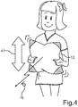
- Fig. 4 illustrates how on the basis of sensor signal 34, a remote control signal 16 may be triggered on the basis of a shaking event 41 for example a repeated movement up and down as a user may achieve it by shaking the remote control unit 12 up and down.
- a shaking event 41 for example a repeated movement up and down as a user may achieve it by shaking the remote control unit 12 up and down.
- Fig. 5 illustrates how a display 23 may be provided in the remote control unit 12 on the basis of light emitting diodes LEDs 42. For the sake of clarity only a few LEDs have been marked with a reference sign.
- Electronic circuit 13 may control the LEDs 42 individually in order to display a specific display content 24.
- the LEDs 42 may be positioned or attached to a flexible carrier, for example a foil or a flexible printed circuit board.
- Fig. 6 indicates, how on the basis of sensor signal 34 an upright position or facial orientation of an image content 24 may be kept even if the remote control unit 12 is turned in a turning action 44 of a user, for example if the user turns the remote control unit 12 by 90° as shown in Fig. 6 . Nevertheless, the display content 24, for example a symbol, stays upright with respect to the position of the user.
- Fig. 7 illustrates how a person 45 may rest a head 46 on the remote control unit 12 due to the cushioned carrier body 14.
- the notification unit 25 the user may be provided with a notification signal 26, for example, as shown in Fig. 7 , an alarm clock signal.
- the user may receive the notification signal 26 as the described vibration 27 and/or an audio signal. Additionally or alternatively, as a notification signal, an incoming phone call may be signaled.
- Vehicle 11 may comprise an autopilot or autonomous driving functionality.
- the remote control unit may be used to operate the at least one vehicle component 18 while vehicle 11 is in an autonomous driving mode.
- a user may then use the cushioned remote control unit 12 for example for resting a head 46. This may increase the comfort while using the vehicle.
- This also allows to set the vehicle seat of the user in a laid-back position as the user may still operate the at least one vehicle component 18 on the basis of the remote control unit 12.
- the idea is to provide a cushion in the vehicle 11 that may additionally be provided with an electronic circuit that may comprise a battery and/or gyroscope and/or manual input unit and/or loudspeaker and/or WIFI-transceiver and or Bluetooth-transceiver.
- the cushion can be used as the remote control unit 12 for predefined functions of the at least one vehicle component 18, for example volume control and/or skip and/or skip back and/or play and or/or pause.
- the cushion may have an upper side and a lower side with different colors and/or materials.
- the manual user input may be received at the corners of the cushion, for example when a respective corner is pressed.
- User input may also be received at buttons of the cushion or pillow. Pressing once or twice may trigger different remote control signals.
- a different design may be provided, for example a plush toy, for example a teddy bear.
- the pillow may be fixed to a charging station by means of a magnet and may then receive inductive electric charging energy.
- a remote control unit in the shape of a plush toy or a pillow may be designed lighter and softer and may therefore be safe in the case of a crash.
- a pillow or a plush toy may be fixed to a charging station by means of a magnet.
- the remote control unit may be used as a pillow and/or for remotely controlling at least one function of at least one vehicle component 18.
- the remote control unit may also be used by a person different from the driver, even a person sitting on a back bench.
- the remote control unit designed as a plush toy and/or a pillow may also be suitable for children.
Landscapes
- Physics & Mathematics (AREA)
- General Physics & Mathematics (AREA)
- Engineering & Computer Science (AREA)
- Computer Networks & Wireless Communication (AREA)
- Toys (AREA)
- Selective Calling Equipment (AREA)
Abstract
Description
- The invention is concerned with a cushioned remote control unit for a vehicle, that is a remote control unit comprising a cushion material. The invention also provides a system comprising the remote control unit and a vehicle that may be controlled by means of the remote control unit.
- Cushioned remote control units are known from
US D684,562 S CN 103908123 A . These remote control units are designed as cushions or pillows that a user may hug or hold close to the body while watching television. - Integrating the electronic circuit of a remote control unit into a cushion or pillow comes with the disadvantage that the soft body of a pillow does not provide enough stability for presenting buttons to a user. If a user presses such a button on a soft surface of a pillow, the pillow will get deformed such that buttons on the surface change their position and the user has to pay more attention in order to find the buttons.
-
US 2017/0069318 A1 describes a cushioned remote control unit in the design of a pillow that comprises a pressure sensor and/or an infrared sensor for detecting the presence of a person. If the presence of a person is not detected, a stand-by mode is activated for reducing the amount of energy used by the remote control unit. - The pillow comprising the sensor for detecting the presence of a person may be difficult to operate by a child that may not be strong enough to trigger a pressure sensor. Also, a child's hands may be too small to be detected by an infrared sensor.
- It is an object of the present invention to provide a cushioned remote control unit for a vehicle that may be reliably operated by users of the vehicle.
- The object is achieved by the subject matter of the independent claims. Advantageous embodiments of the invention are described by the dependent claims, the following description and the drawings.
- The invention provides a cushioned remote control unit for a vehicle. The remote control unit comprises an electronic circuit for generating at least one remote control signal. Such an electronic circuit may be based on a known technology for providing a remote control unit. Examples for remote control signals are: volume control, skip forward in a playlist, skip backwards in the playlist, play, pause, stand-by. The electronic circuit is integrated into a carrier body that comprises a cushion material that covers at least a part of the electronic circuit. In other words, the carrier body is a soft body that may be filled with a cushion material, for example wool or wadding. In this carrier body, the electronic circuit may be fully or partly integrated or arranged.
- In order to support a user in handling or operating the remote control unit, the electronic circuit comprises a sensor unit that is designed to sense and signal an acceleration and/or spatial orientation (e.g. up/down) of the remote control unit. The sensor unit may comprise, for example, a gyroscope and/or an accelerometer for sensing the spatial orientation and/or the acceleration of the remote control unit. The electronic circuit is designed to trigger at least one of the at least one remote control signal in dependence on a sensor signal of the sensor unit. In other words, for selecting and/or triggering and/or starting a remote control signal, it suffices to move the whole remote control unit such that the remote control unit is accelerated and/or changes its spatial orientation. Therefore, by handling the remote control unit as a whole, for example by handling a pillow, a remote control signal may be generated by means of the cushioned remote control unit. The electronic circuit for generating the at least one remote control signal may additionally comprise, for example, a battery for powering the electronic circuit, a manual input unit for triggering at least one more remote control signal and/or a WIFI-sending unit and/or Bluetooth-sending unit and/or an infrared-sending unit for transmitting the at least one remote control signal and/or a loudspeaker for emitting a sound signal. Providing a cushioned remote control unit in a vehicle provides the additional advantage that the remote control unit may provide safety when the vehicle crashes and the soft carrier body may prevent damage to a person when the person is hit by the remote control unit due to the crash. The electronic circuit may also comprise a receiving unit for receiving data from a communication unit of the vehicle.
- The invention also comprises embodiments that provide additional advantages.
- In one embodiment the carrier body is designed as a plush toy, for example as plush animal, e.g. a teddy bear. The remote control unit may then additionally be used for entertaining a child who travels in the vehicle. Alternatively, the cushioned remote control unit may have a carrier body that is designed as a cushion or pillow. This provides the advantage that a person may rest a head and/or arm on the remote control unit.
- In one embodiment the electronic circuit of the remote control unit is designed to select one out of several predefined remote control signals for sending, wherein the selection depends on which side of the carrier body points into a predefined direction (e.g. upwards) according to the sensor signal. In other words, as has already been described, the electronic circuit is designed to trigger at least one of the at least one remote control signal in dependence on the sensor signal of the sensor unit. On the basis of the sensor signal, the electronic circuit detects which side of the carrier body points into the predefined direction, e.g. upwards, and depending on which side it is, the remote control signal is selected. Thus, a user may change the remote control function by turning over the remote control unit. The remote control unit may be directly sent out in reaction to the turning movement or the remote control unit may be sent out, if an additional user input is received, for example at a user input unit.
- In one embodiment the electronic circuit is designed to switch into a stand-by mode, if the sensor signal signals that a predefined side of the carrier body is pointing upwards. This side of the carrier body is called here an "inactive side". In other words, the electronic control unit may have an "active side" and an "inactive side". Thus, by holding the corresponding side upwards or positioning the remote control unit with the corresponding side upwards the remote control unit may be switched between an active mode and a stand-by-mode. The active side and the inactive side may be marked by different colors and/or different materials.
- In one embodiment the electronic circuit comprises a display for displaying a display content related to the at least one remote control signal. For example, as a respective display content, a button or icon representing the respective control function associated with a remote control signal may be presented or displayed. Such a display content may indicate to the user which remote control signal will be generated, if the remote control unit is pressed or touched at the respective position of the display content and/or when the remote control unit is moved or accelerated in a specific, predefined manner.
- According to one embodiment the electronic circuit is designed to adapt an upward-orientation of the display content as a function of the sensor signal. In other words, when turning different sides up, the control display adapts the orientation such that although the remote control unit may be rotated or position with a different side up, the display content will keep an upright position as seen from the user's point of view. This provides the flexibility of positioning the remote control unit in different orientations and the display content will still be recognizable for the user, i.e. the display content will stay upright.
- In one embodiment the electronic circuit is designed to detect a predefined shaking event on the basis of a temporal progression of the sensor signal and to generate a predefined remote control signal when the shaking event is detected. In other words, by means of a time signal generated by the sensor unit, a shaking event is detected. Such a shaking event may comprise that the remote control unit is shaken up and down and/or to and fro and/or left and right. For example, the shaking event may comprise at least one turning point in a shaking movement. When the shaking event is sensed, the electronic circuit will generate a predefined remote control signal associated with the shaking event. Thus, no button needs to be pressed for triggering the remote control signal.
- In one embodiment the electronic circuit comprises a notification unit for generating a notification signal for a user, wherein the notification unit is designed to generate, as the notification signal, a vibration and/or an audio output in the carrier body in dependence on a predefined notification event. The notification event may comprise, for example, an incoming phone call that is signaled to the remote control unit by the vehicle and/or a mobile phone, and/or an alarm clock signal indicating that an alarm should be signaled to a user. As the remote control unit provides a cushioned carrier body, a user may rest the head on the remote control unit. Then, if the notification unit signals the notification signal by means of a vibration, the user will directly feel and/or hear the vibration in the remote control unit. An audio output may be of low volume as a user will hear the audio output even at low volume, if the head rests on the remote control unit. The transfer of the remote control signal and/or data signal may be based on a Bluetooth protocol and/or Wifi protocol that respectively allows for 2way traffic, i.e. not just sending but also receiving information / signals.
- In one embodiment the carrier body comprises a salient part or a protruding part, that is a part of convex shape. The term "convex shape" means "convex" in the mathematical sense. In the case of a carrier body designed as a pillow, the salient part may be a pillow corner. In the case of a carrier body designed as a plush toy or plush animal, the salient parts may be, for example, an ear or an arm or a leg of the plush animal. The electronic circuit comprises an input unit for receiving a manual user input and the input unit is arranged in the salient part. Therefore, by squeezing or touching or pressing the salient part, a specific remote control signal may be triggered by the user. Which signal is triggered may depend on the spatial orientation of the remote control unit as signaled by the sensor signal of the sensor unit.
- In one embodiment the electronic circuit comprises a charging unit for inductive charging. The charging unit may be designed as is known from the prior art. Additionally, at least one holding element is arranged at the charging unit for holding the charging unit in a predefined charging position with regard to an external charging station, that is a charging station of the vehicle. Such a holding element is preferably provided in the form of a permanent magnet. Thus, by laying down or positioning the remote control unit at the charging station, the holding element will fix the charging unit to the charging station. Therefore, although the electronic circuit is positioned inside a cushioned material and may therefore not have the stability to stay in position with regard to this charging station, the at least one holding element will secure the charging unit at the charging station.
- The invention also comprises a system. Such a system is a combination of the described remote control unit and a motor vehicle. The motor vehicle comprises a communication unit for receiving at least one remote control signal from the remote control unit and/or sending a data signal to the remote control unit. As has already been described, the remote control unit will generate the at least one remote control signal. To this end, the electronic circuit of the remote control unit will evaluate a sensor signal of a sensor unit that is designed to sense and signal an acceleration and/or spatial orientation of the remote control unit. The motor vehicle is further designed to control at least one vehicle component in dependence on the at least one remote control signal. One vehicle component can be, e.g., an infotainment system. For example, a playback of a media content may be controlled in the infotainment system. Additionally or alternatively, the remote control unit may function as a gaming controller for a computer game that may be operated in the vehicle. By means of the data signal, a functionality of the remote control unit may be triggered by the vehicle.
- The inventive motor vehicle comprises a charging station for inductive charging. Further, a fixing unit for holding the remote control unit in a predefined charging position at the charging station is provided. The fixing unit may comprise, for example, at least one permanent magnet for fixing the charging unit of the remote control unit to the charging station. The fixing unit may also comprise at least one thermomagnetic material that may interact with a permanent magnet that constitutes a holding element of the remote control unit. The fixing unit and the corresponding holding element of the charging unit of the remote control unit may be designed as a so called pogo connector.
- The inventive motor vehicle may be designed as a passenger vehicle and/or a truck.
- The invention also comprises the combinations of features of the described embodiments.
- In the following an implementation example of the invention is described. The drawings show:
- Fig. 1
- a schematic illustration of an embodiment of the system according to the invention;
- Fig. 2
- a schematic illustration of a charging station of a vehicle of the system;
- Fig. 3
- a schematic illustration of a cushioned remote control unit of the system in two different spatial orientations;
- Fig. 4
- a schematic illustration of the remote control unit while detecting a shaking event;
- Fig. 5
- a schematic illustration of the remote control unit displaying a display content by means of a display;
- Fig. 6
- a schematic illustration of the remote control unit adapting an upward-orientation of the display content; and
- Fig. 7
- a schematic illustration of the remote control unit generating a notification signal while a person is resting a head on the remote control unit.
- The embodiment explained in the following is a preferred embodiment of the invention. However, in the embodiment, the described components of the embodiment each represent individual features of the invention which are to be considered independently of each other and which each develop the invention also independently of each other and thereby are also to be regarded as a component of the invention in individual manner or in another than the shown combination. Furthermore, the described embodiment can also be supplemented by further features of the invention already described.
- In the figures identical reference signs indicate elements that provide the same function.
-
Fig. 1 shows asystem 10 that may comprise amotor vehicle 11 and a cushionedremote control unit 12 for thevehicle 11. The remote control unit may comprise anelectronic circuit 13 and acarrier body 14 wherein thecarrier body 14 may comprise a cushionedmaterial 15, for example a filling of wool or wadding. For providing the remote control functionality,electronic circuit 13 may be designed to generate or send out at least oneremote control signal 16 which may be received by acommunication unit 17 of thevehicle 11. Thecommunication unit 17 may control at least onevehicle component 18 as a function of the received at least oneremote control signal 16. To this end, thecommunication unit 17 may generate a corresponding control signal and/or may forward the at least one receivedremote control signal 16 to the at least onevehicle component 18. - For sending out a
remote control signal 16,electronic circuit 13 may comprise a sendingunit 19 which may be based on WIFI-technology and/or Bluetooth-technology and/or infrared technology. Theremote control unit 12 may also comprise a receiving unit (not shown) for receiving a data signal from thecommunication unit 17, e.g. a data signal indicating an incoming telephone call. - For triggering a
remote control signal 16, a user may operate theremote control unit 12. To this end, at least oneinput unit 20 for receiving a manual user input may be provided. Arespective input unit 20 may be positioned or arranged in a respectivesalient part 21 of convex shape of thecarrier body 14. -
Carrier body 14 may be designed as a pillow as shown inFig. 1 . A respectivesalient part 21 may be provided by a respective corner of the pillow.Carrier body 14 may be designed as a plush toy, especially a plush animal. A salient part may be provided by an arm or an ear or a leg of the plush toy. -
Manual user input 22 may be, for example, a signal indicating that therespective input unit 20 has been squeezed by the user. For indicating whichremote control signal 16 is associated with therespective input unit 20, arespective display 23 may be provided that may also be situated in the respectivesalient part 21. By means of therespective display 23, arespective display content 24 may be displayed, indicating the associatedremote control signal 16.Fig. 1 indicates on the right hand side, how adifferent display content 24 may be displayed with one and thesame display 23 for indicating that different remote control signals 16 may be associated with thesame input unit 20, wherein oneremote control signal 16 may be associated at a time. -
Electronic circuit 13 may also comprise an actuator unit ornotification unit 25 that may output anotification signal 26 to the user. For example, as innotification signal 26, avibration 27 may be generated by thenotification unit 25. Thenotification unit 25 may comprise an electric motor with an unbalanced weight for generatingvibration 27. Additionally or alternatively,notification unit 25 may comprise a loudspeaker for generating an audio output. - For operating the
electronic circuit 13, anenergy storage 28 may be provided that may comprise at least one battery. For charging theenergy storage 28, a chargingunit 29 may be provided in theelectronic circuit 13. The chargingunit 29 may be designed to recharge theenergy storage 28 on the basis of inductive charging as is known from the prior art. For holding the chargingunit 29 close to a chargingstation 30 ofvehicle 11, a holdingelement 31 may be provided, for example a permanent magnet.Charging station 30 may comprise acorresponding fixing unit 32 to which holdingelement 31 may be attached or fixed. Fixingunit 32 may comprise at least one permanent magnet and/or at least one thermomagnetic element. -
Electronic circuit 13 may comprise a sensor unit S which may indicate a movement and/or a spatial orientation. Sensor unit S may comprise a gyroscope and/or an accelerometer for signaling or generating asensor signal 34 indicating an acceleration and/or spatial orientation of theremote control unit 12. -
Fig. 2 illustrates, how the chargingstation 30 may comprise severaldifferent fixing units 32 for allowing theremote control unit 12 to be charged atdifferent charging positions 33 insidevehicle 11, for example at different seats. - The respective
salient parts 21 may be marked or indicated by a different color regarding the rest of thecarrier body 14 and/or by a different material, for example a leather corner. -
Fig. 3 illustrates how on the basis ofsensor signal 34remote control unit 12 may be switched between anactive state 35 and an inactive state or stand-by mode 36 depending on a spatial orientation ofremote control unit 12. Theelectronic circuit 13 may be designed to switch into theactive state 35 if a predefinedactive side 37 points upwards. A switching command or change of operation mode may be generated if a flip over 39 is detected that is if aninactive side 40 points upwards. Theactive side 37 and theinactive side 40 may be marked by different colors and/or materials.
Command 38 - Thus by positioning the
respective side active state 35 and the stand-by mode 36. -
Fig. 4 illustrates how on the basis ofsensor signal 34, aremote control signal 16 may be triggered on the basis of a shakingevent 41 for example a repeated movement up and down as a user may achieve it by shaking theremote control unit 12 up and down. -
Fig. 5 illustrates how adisplay 23 may be provided in theremote control unit 12 on the basis of light emittingdiodes LEDs 42. For the sake of clarity only a few LEDs have been marked with a reference sign.Electronic circuit 13 may control theLEDs 42 individually in order to display aspecific display content 24. TheLEDs 42 may be positioned or attached to a flexible carrier, for example a foil or a flexible printed circuit board. -
Fig. 6 indicates, how on the basis ofsensor signal 34 an upright position or facial orientation of animage content 24 may be kept even if theremote control unit 12 is turned in a turningaction 44 of a user, for example if the user turns theremote control unit 12 by 90° as shown inFig. 6 . Nevertheless, thedisplay content 24, for example a symbol, stays upright with respect to the position of the user. -
Fig. 7 illustrates how aperson 45 may rest ahead 46 on theremote control unit 12 due to thecushioned carrier body 14. By means of thenotification unit 25, the user may be provided with anotification signal 26, for example, as shown inFig. 7 , an alarm clock signal. The user may receive thenotification signal 26 as the describedvibration 27 and/or an audio signal. Additionally or alternatively, as a notification signal, an incoming phone call may be signaled. -
Vehicle 11 may comprise an autopilot or autonomous driving functionality. The remote control unit may be used to operate the at least onevehicle component 18 whilevehicle 11 is in an autonomous driving mode. A user may then use the cushionedremote control unit 12 for example for resting ahead 46. This may increase the comfort while using the vehicle. This also allows to set the vehicle seat of the user in a laid-back position as the user may still operate the at least onevehicle component 18 on the basis of theremote control unit 12. - The idea is to provide a cushion in the
vehicle 11 that may additionally be provided with an electronic circuit that may comprise a battery and/or gyroscope and/or manual input unit and/or loudspeaker and/or WIFI-transceiver and or Bluetooth-transceiver. The cushion can be used as theremote control unit 12 for predefined functions of the at least onevehicle component 18, for example volume control and/or skip and/or skip back and/or play and or/or pause. - When the cushion is turned around, i.e. another side of the cushion is turned up, different remote control signals may be provided.
- The cushion may have an upper side and a lower side with different colors and/or materials. The manual user input may be received at the corners of the cushion, for example when a respective corner is pressed. User input may also be received at buttons of the cushion or pillow. Pressing once or twice may trigger different remote control signals. Instead of a cushion or pillow, a different design may be provided, for example a plush toy, for example a teddy bear.
- The pillow may be fixed to a charging station by means of a magnet and may then receive inductive electric charging energy.
- The advantage is that a remote control unit in the shape of a plush toy or a pillow may be designed lighter and softer and may therefore be safe in the case of a crash. A pillow or a plush toy may be fixed to a charging station by means of a magnet. During autonomous driving phase, the remote control unit may be used as a pillow and/or for remotely controlling at least one function of at least one
vehicle component 18. The remote control unit may also be used by a person different from the driver, even a person sitting on a back bench. The remote control unit designed as a plush toy and/or a pillow may also be suitable for children. - Overall, the example shows how a pillow with a remote control functionality is provided by the invention.
Claims (10)
- Cushioned remote control unit (12) for a vehicle (11), the remote control unit (12) comprising an electronic circuit (13) for generating at least one remote control signal (16), wherein the electronic circuit (13) is integrated into a carrier body (14) that comprises a cushion material (15) that covers at least a part of the electronic circuit (13),
characterized in that
the electronic circuit (13) comprises a sensor unit (S) that is designed to sense and signal an acceleration and/or spatial orientation of the remote control unit (12), wherein the electronic circuit (13) is designed to trigger at least one of the at least one remote control signal (16) in dependence on a sensor signal (34) of the sensor unit (S). - Remote control unit (12) according to claim 1, wherein the carrier body (14) is designed as a plush toy or a pillow.
- Remote control unit (12) according to any of the preceding claims, wherein the electronic circuit (13) is designed to select one out of several predefined remote control signals (16) for sending, wherein the selection depends on which side of the carrier body points upwards according to the sensor signal (34).
- Remote control unit (12) according to any of the preceding claims, wherein the electronic circuit (13) is designed to switch into a stand-by mode (36), if the sensor signal signals (34) that a predefined inactive side (40) of the carrier body (14) is pointing into a predefined direction.
- Remote control unit (12) according to any of the preceding claims, wherein the electronic circuit (13) comprises a display (23) for displaying a display content (24) related to the at least one remote control signal (16) and wherein the electronic circuit (13) is designed to adapt an upward-orientation of the display content (24) as a function of the sensor signal (34).
- Remote control unit (12) according to any of the preceding claims, wherein the electronic circuit (13) is designed to detect a predefined shaking event (41) on the basis of a temporal progression of the sensor signal (34) and to generate a predefined remote control signal (16) when the shaking event (41) is detected.
- Remote control unit (12) according to any of the preceding claims, wherein the electronic circuit (13) comprises a notification unit (25) for generating a notification signal (26) for a user (45), wherein the notification unit (25) is designed to generate, as the notification signal (26), a vibration (27) and/or an audio output in the carrier body (14) in dependence on a predefined notification event.
- Remote control unit (12) according to any of the preceding claims, wherein the carrier body (14) comprises a salient part (21) and wherein the electronic circuit (13) comprises an input unit (20) for receiving a manual user input (22) and the input unit (20) is arranged in the salient part (21).
- Remote control unit (12) according to any of the preceding claims, wherein the electronic circuit (12) comprises a charging unit (29) for inductive charging, wherein at least one holding element (31) is arranged at the charging unit (29) for holding the charging unit (29) in a predefined charging position (33) at a charging station (30) of the vehicle (11).
- System (10) comprising a remote control unit (12) according to any of the preceding claims and a motor vehicle (11) with a communication unit (17) for receiving at least one remote control signal (16) from the remote control unit (12), wherein the motor vehicle (11) is designed to control at least one vehicle component (18) in dependence on the at least one remote control signal,
characterized in that
the motor vehicle (11) comprises a charging station (30) for inductive charging and a fixing unit (32) for holding the remote control unit (12) in a predefined charging position (33) at the charging station (30).
Priority Applications (1)
| Application Number | Priority Date | Filing Date | Title |
|---|---|---|---|
| EP18209449.0A EP3660803B1 (en) | 2018-11-30 | 2018-11-30 | Cushioned remote control unit for a vehicle and system comprising both the control unit and the vehicle |
Applications Claiming Priority (1)
| Application Number | Priority Date | Filing Date | Title |
|---|---|---|---|
| EP18209449.0A EP3660803B1 (en) | 2018-11-30 | 2018-11-30 | Cushioned remote control unit for a vehicle and system comprising both the control unit and the vehicle |
Publications (2)
| Publication Number | Publication Date |
|---|---|
| EP3660803A1 true EP3660803A1 (en) | 2020-06-03 |
| EP3660803B1 EP3660803B1 (en) | 2021-09-22 |
Family
ID=64564636
Family Applications (1)
| Application Number | Title | Priority Date | Filing Date |
|---|---|---|---|
| EP18209449.0A Active EP3660803B1 (en) | 2018-11-30 | 2018-11-30 | Cushioned remote control unit for a vehicle and system comprising both the control unit and the vehicle |
Country Status (1)
| Country | Link |
|---|---|
| EP (1) | EP3660803B1 (en) |
Cited By (1)
| Publication number | Priority date | Publication date | Assignee | Title |
|---|---|---|---|---|
| WO2024262585A1 (en) * | 2023-06-21 | 2024-12-26 | テイ・エス テック株式会社 | Vehicle interior system |
Citations (5)
| Publication number | Priority date | Publication date | Assignee | Title |
|---|---|---|---|---|
| WO1990002390A1 (en) * | 1988-08-26 | 1990-03-08 | Scientific Applied Research (S.A.R.) Plc | Apparatus for controlling a television receiver or the like |
| USD684562S1 (en) | 2011-03-09 | 2013-06-18 | Ewig Industries Macao Commercial Offshore Ltd. | Pillow remote control |
| CN103908123A (en) | 2012-12-29 | 2014-07-09 | 袁小林 | Novel throw pillow |
| US20170069318A1 (en) | 2014-12-12 | 2017-03-09 | Raymond Henry Hardman | Pillow remote controller using audible commands |
| EP3279881A1 (en) * | 2016-08-05 | 2018-02-07 | Alexander Hakenjos | Remote control and method for controlling the same |
-
2018
- 2018-11-30 EP EP18209449.0A patent/EP3660803B1/en active Active
Patent Citations (5)
| Publication number | Priority date | Publication date | Assignee | Title |
|---|---|---|---|---|
| WO1990002390A1 (en) * | 1988-08-26 | 1990-03-08 | Scientific Applied Research (S.A.R.) Plc | Apparatus for controlling a television receiver or the like |
| USD684562S1 (en) | 2011-03-09 | 2013-06-18 | Ewig Industries Macao Commercial Offshore Ltd. | Pillow remote control |
| CN103908123A (en) | 2012-12-29 | 2014-07-09 | 袁小林 | Novel throw pillow |
| US20170069318A1 (en) | 2014-12-12 | 2017-03-09 | Raymond Henry Hardman | Pillow remote controller using audible commands |
| EP3279881A1 (en) * | 2016-08-05 | 2018-02-07 | Alexander Hakenjos | Remote control and method for controlling the same |
Cited By (1)
| Publication number | Priority date | Publication date | Assignee | Title |
|---|---|---|---|---|
| WO2024262585A1 (en) * | 2023-06-21 | 2024-12-26 | テイ・エス テック株式会社 | Vehicle interior system |
Also Published As
| Publication number | Publication date |
|---|---|
| EP3660803B1 (en) | 2021-09-22 |
Similar Documents
| Publication | Publication Date | Title |
|---|---|---|
| US11400366B2 (en) | Controller | |
| US9814975B2 (en) | Gaming device with haptic effect isolated to user input elements | |
| JP6262853B2 (en) | Method for adjusting vehicle seat and system for adjusting vehicle seat | |
| CN202191703U (en) | Remote control emitter arranged on personal portable touch communication equipment | |
| KR101637985B1 (en) | Case for mobile device | |
| CA2625810A1 (en) | Mobile device customizer | |
| US10717378B2 (en) | Headrest for a vehicle seat | |
| CN101107795A (en) | Electronic device control system and control signal transmitting device | |
| US20040259070A1 (en) | Child/infant play and entertainment devices including electronic displays | |
| KR20210017243A (en) | In-vehicle control apparatus using detachable knob and method for controlling the same | |
| TWI725865B (en) | Intelligent vehicle system | |
| EP3660803B1 (en) | Cushioned remote control unit for a vehicle and system comprising both the control unit and the vehicle | |
| US11660964B2 (en) | System and method for controlling functions of a vehicle using a detachable control device | |
| US8320961B2 (en) | Apparatus for a tangible interface | |
| KR102635790B1 (en) | Passenger restraint device with integrated audio system | |
| KR20170027607A (en) | Wearable device and method for controlling the same | |
| US20050225951A1 (en) | Electronic apparatus | |
| JP2019530123A (en) | Patch type controller | |
| CN207285693U (en) | Intelligent seat base reaches intelligent seat including it | |
| KR101355195B1 (en) | Universal control apparatus for device in vehicle | |
| KR101980601B1 (en) | Remote control device | |
| KR101841536B1 (en) | A smart system for generating SOS signal and method thereof | |
| EP1974248A1 (en) | Charging stand | |
| CN201917881U (en) | Stylus pen | |
| KR101853697B1 (en) | Smartphone case with remote control function |
Legal Events
| Date | Code | Title | Description |
|---|---|---|---|
| PUAI | Public reference made under article 153(3) epc to a published international application that has entered the european phase |
Free format text: ORIGINAL CODE: 0009012 |
|
| STAA | Information on the status of an ep patent application or granted ep patent |
Free format text: STATUS: THE APPLICATION HAS BEEN PUBLISHED |
|
| AK | Designated contracting states |
Kind code of ref document: A1 Designated state(s): AL AT BE BG CH CY CZ DE DK EE ES FI FR GB GR HR HU IE IS IT LI LT LU LV MC MK MT NL NO PL PT RO RS SE SI SK SM TR |
|
| AX | Request for extension of the european patent |
Extension state: BA ME |
|
| STAA | Information on the status of an ep patent application or granted ep patent |
Free format text: STATUS: REQUEST FOR EXAMINATION WAS MADE |
|
| 17P | Request for examination filed |
Effective date: 20201203 |
|
| RBV | Designated contracting states (corrected) |
Designated state(s): AL AT BE BG CH CY CZ DE DK EE ES FI FR GB GR HR HU IE IS IT LI LT LU LV MC MK MT NL NO PL PT RO RS SE SI SK SM TR |
|
| GRAP | Despatch of communication of intention to grant a patent |
Free format text: ORIGINAL CODE: EPIDOSNIGR1 |
|
| STAA | Information on the status of an ep patent application or granted ep patent |
Free format text: STATUS: GRANT OF PATENT IS INTENDED |
|
| INTG | Intention to grant announced |
Effective date: 20210531 |
|
| GRAS | Grant fee paid |
Free format text: ORIGINAL CODE: EPIDOSNIGR3 |
|
| GRAA | (expected) grant |
Free format text: ORIGINAL CODE: 0009210 |
|
| STAA | Information on the status of an ep patent application or granted ep patent |
Free format text: STATUS: THE PATENT HAS BEEN GRANTED |
|
| AK | Designated contracting states |
Kind code of ref document: B1 Designated state(s): AL AT BE BG CH CY CZ DE DK EE ES FI FR GB GR HR HU IE IS IT LI LT LU LV MC MK MT NL NO PL PT RO RS SE SI SK SM TR |
|
| REG | Reference to a national code |
Ref country code: GB Ref legal event code: FG4D |
|
| REG | Reference to a national code |
Ref country code: IE Ref legal event code: FG4D |
|
| REG | Reference to a national code |
Ref country code: DE Ref legal event code: R096 Ref document number: 602018023863 Country of ref document: DE |
|
| REG | Reference to a national code |
Ref country code: CH Ref legal event code: EP Ref country code: AT Ref legal event code: REF Ref document number: 1432920 Country of ref document: AT Kind code of ref document: T Effective date: 20211015 |
|
| REG | Reference to a national code |
Ref country code: LT Ref legal event code: MG9D |
|
| REG | Reference to a national code |
Ref country code: NL Ref legal event code: MP Effective date: 20210922 |
|
| PG25 | Lapsed in a contracting state [announced via postgrant information from national office to epo] |
Ref country code: RS Free format text: LAPSE BECAUSE OF FAILURE TO SUBMIT A TRANSLATION OF THE DESCRIPTION OR TO PAY THE FEE WITHIN THE PRESCRIBED TIME-LIMIT Effective date: 20210922 Ref country code: SE Free format text: LAPSE BECAUSE OF FAILURE TO SUBMIT A TRANSLATION OF THE DESCRIPTION OR TO PAY THE FEE WITHIN THE PRESCRIBED TIME-LIMIT Effective date: 20210922 Ref country code: HR Free format text: LAPSE BECAUSE OF FAILURE TO SUBMIT A TRANSLATION OF THE DESCRIPTION OR TO PAY THE FEE WITHIN THE PRESCRIBED TIME-LIMIT Effective date: 20210922 Ref country code: FI Free format text: LAPSE BECAUSE OF FAILURE TO SUBMIT A TRANSLATION OF THE DESCRIPTION OR TO PAY THE FEE WITHIN THE PRESCRIBED TIME-LIMIT Effective date: 20210922 Ref country code: NO Free format text: LAPSE BECAUSE OF FAILURE TO SUBMIT A TRANSLATION OF THE DESCRIPTION OR TO PAY THE FEE WITHIN THE PRESCRIBED TIME-LIMIT Effective date: 20211222 Ref country code: BG Free format text: LAPSE BECAUSE OF FAILURE TO SUBMIT A TRANSLATION OF THE DESCRIPTION OR TO PAY THE FEE WITHIN THE PRESCRIBED TIME-LIMIT Effective date: 20211222 Ref country code: LT Free format text: LAPSE BECAUSE OF FAILURE TO SUBMIT A TRANSLATION OF THE DESCRIPTION OR TO PAY THE FEE WITHIN THE PRESCRIBED TIME-LIMIT Effective date: 20210922 |
|
| REG | Reference to a national code |
Ref country code: AT Ref legal event code: MK05 Ref document number: 1432920 Country of ref document: AT Kind code of ref document: T Effective date: 20210922 |
|
| PG25 | Lapsed in a contracting state [announced via postgrant information from national office to epo] |
Ref country code: LV Free format text: LAPSE BECAUSE OF FAILURE TO SUBMIT A TRANSLATION OF THE DESCRIPTION OR TO PAY THE FEE WITHIN THE PRESCRIBED TIME-LIMIT Effective date: 20210922 Ref country code: GR Free format text: LAPSE BECAUSE OF FAILURE TO SUBMIT A TRANSLATION OF THE DESCRIPTION OR TO PAY THE FEE WITHIN THE PRESCRIBED TIME-LIMIT Effective date: 20211223 |
|
| PG25 | Lapsed in a contracting state [announced via postgrant information from national office to epo] |
Ref country code: AT Free format text: LAPSE BECAUSE OF FAILURE TO SUBMIT A TRANSLATION OF THE DESCRIPTION OR TO PAY THE FEE WITHIN THE PRESCRIBED TIME-LIMIT Effective date: 20210922 |
|
| PG25 | Lapsed in a contracting state [announced via postgrant information from national office to epo] |
Ref country code: IS Free format text: LAPSE BECAUSE OF FAILURE TO SUBMIT A TRANSLATION OF THE DESCRIPTION OR TO PAY THE FEE WITHIN THE PRESCRIBED TIME-LIMIT Effective date: 20220122 Ref country code: SK Free format text: LAPSE BECAUSE OF FAILURE TO SUBMIT A TRANSLATION OF THE DESCRIPTION OR TO PAY THE FEE WITHIN THE PRESCRIBED TIME-LIMIT Effective date: 20210922 Ref country code: RO Free format text: LAPSE BECAUSE OF FAILURE TO SUBMIT A TRANSLATION OF THE DESCRIPTION OR TO PAY THE FEE WITHIN THE PRESCRIBED TIME-LIMIT Effective date: 20210922 Ref country code: PT Free format text: LAPSE BECAUSE OF FAILURE TO SUBMIT A TRANSLATION OF THE DESCRIPTION OR TO PAY THE FEE WITHIN THE PRESCRIBED TIME-LIMIT Effective date: 20220124 Ref country code: PL Free format text: LAPSE BECAUSE OF FAILURE TO SUBMIT A TRANSLATION OF THE DESCRIPTION OR TO PAY THE FEE WITHIN THE PRESCRIBED TIME-LIMIT Effective date: 20210922 Ref country code: NL Free format text: LAPSE BECAUSE OF FAILURE TO SUBMIT A TRANSLATION OF THE DESCRIPTION OR TO PAY THE FEE WITHIN THE PRESCRIBED TIME-LIMIT Effective date: 20210922 Ref country code: ES Free format text: LAPSE BECAUSE OF FAILURE TO SUBMIT A TRANSLATION OF THE DESCRIPTION OR TO PAY THE FEE WITHIN THE PRESCRIBED TIME-LIMIT Effective date: 20210922 Ref country code: EE Free format text: LAPSE BECAUSE OF FAILURE TO SUBMIT A TRANSLATION OF THE DESCRIPTION OR TO PAY THE FEE WITHIN THE PRESCRIBED TIME-LIMIT Effective date: 20210922 Ref country code: CZ Free format text: LAPSE BECAUSE OF FAILURE TO SUBMIT A TRANSLATION OF THE DESCRIPTION OR TO PAY THE FEE WITHIN THE PRESCRIBED TIME-LIMIT Effective date: 20210922 Ref country code: AL Free format text: LAPSE BECAUSE OF FAILURE TO SUBMIT A TRANSLATION OF THE DESCRIPTION OR TO PAY THE FEE WITHIN THE PRESCRIBED TIME-LIMIT Effective date: 20210922 |
|
| REG | Reference to a national code |
Ref country code: DE Ref legal event code: R097 Ref document number: 602018023863 Country of ref document: DE |
|
| PG25 | Lapsed in a contracting state [announced via postgrant information from national office to epo] |
Ref country code: MC Free format text: LAPSE BECAUSE OF FAILURE TO SUBMIT A TRANSLATION OF THE DESCRIPTION OR TO PAY THE FEE WITHIN THE PRESCRIBED TIME-LIMIT Effective date: 20210922 |
|
| REG | Reference to a national code |
Ref country code: CH Ref legal event code: PL |
|
| PG25 | Lapsed in a contracting state [announced via postgrant information from national office to epo] |
Ref country code: LU Free format text: LAPSE BECAUSE OF NON-PAYMENT OF DUE FEES Effective date: 20211130 Ref country code: DK Free format text: LAPSE BECAUSE OF FAILURE TO SUBMIT A TRANSLATION OF THE DESCRIPTION OR TO PAY THE FEE WITHIN THE PRESCRIBED TIME-LIMIT Effective date: 20210922 Ref country code: BE Free format text: LAPSE BECAUSE OF NON-PAYMENT OF DUE FEES Effective date: 20211130 |
|
| PLBE | No opposition filed within time limit |
Free format text: ORIGINAL CODE: 0009261 |
|
| STAA | Information on the status of an ep patent application or granted ep patent |
Free format text: STATUS: NO OPPOSITION FILED WITHIN TIME LIMIT |
|
| REG | Reference to a national code |
Ref country code: BE Ref legal event code: MM Effective date: 20211130 |
|
| 26N | No opposition filed |
Effective date: 20220623 |
|
| PG25 | Lapsed in a contracting state [announced via postgrant information from national office to epo] |
Ref country code: IE Free format text: LAPSE BECAUSE OF NON-PAYMENT OF DUE FEES Effective date: 20211130 |
|
| PG25 | Lapsed in a contracting state [announced via postgrant information from national office to epo] |
Ref country code: SI Free format text: LAPSE BECAUSE OF FAILURE TO SUBMIT A TRANSLATION OF THE DESCRIPTION OR TO PAY THE FEE WITHIN THE PRESCRIBED TIME-LIMIT Effective date: 20210922 |
|
| PG25 | Lapsed in a contracting state [announced via postgrant information from national office to epo] |
Ref country code: IT Free format text: LAPSE BECAUSE OF FAILURE TO SUBMIT A TRANSLATION OF THE DESCRIPTION OR TO PAY THE FEE WITHIN THE PRESCRIBED TIME-LIMIT Effective date: 20210922 |
|
| PG25 | Lapsed in a contracting state [announced via postgrant information from national office to epo] |
Ref country code: CY Free format text: LAPSE BECAUSE OF FAILURE TO SUBMIT A TRANSLATION OF THE DESCRIPTION OR TO PAY THE FEE WITHIN THE PRESCRIBED TIME-LIMIT Effective date: 20210922 |
|
| P01 | Opt-out of the competence of the unified patent court (upc) registered |
Effective date: 20230530 |
|
| PG25 | Lapsed in a contracting state [announced via postgrant information from national office to epo] |
Ref country code: SM Free format text: LAPSE BECAUSE OF FAILURE TO SUBMIT A TRANSLATION OF THE DESCRIPTION OR TO PAY THE FEE WITHIN THE PRESCRIBED TIME-LIMIT Effective date: 20210922 Ref country code: LI Free format text: LAPSE BECAUSE OF NON-PAYMENT OF DUE FEES Effective date: 20220630 Ref country code: HU Free format text: LAPSE BECAUSE OF FAILURE TO SUBMIT A TRANSLATION OF THE DESCRIPTION OR TO PAY THE FEE WITHIN THE PRESCRIBED TIME-LIMIT; INVALID AB INITIO Effective date: 20181130 Ref country code: CH Free format text: LAPSE BECAUSE OF NON-PAYMENT OF DUE FEES Effective date: 20220630 |
|
| PG25 | Lapsed in a contracting state [announced via postgrant information from national office to epo] |
Ref country code: MK Free format text: LAPSE BECAUSE OF FAILURE TO SUBMIT A TRANSLATION OF THE DESCRIPTION OR TO PAY THE FEE WITHIN THE PRESCRIBED TIME-LIMIT Effective date: 20210922 |
|
| PG25 | Lapsed in a contracting state [announced via postgrant information from national office to epo] |
Ref country code: TR Free format text: LAPSE BECAUSE OF FAILURE TO SUBMIT A TRANSLATION OF THE DESCRIPTION OR TO PAY THE FEE WITHIN THE PRESCRIBED TIME-LIMIT Effective date: 20210922 |
|
| PG25 | Lapsed in a contracting state [announced via postgrant information from national office to epo] |
Ref country code: MT Free format text: LAPSE BECAUSE OF FAILURE TO SUBMIT A TRANSLATION OF THE DESCRIPTION OR TO PAY THE FEE WITHIN THE PRESCRIBED TIME-LIMIT Effective date: 20210922 |
|
| PGFP | Annual fee paid to national office [announced via postgrant information from national office to epo] |
Ref country code: DE Payment date: 20251130 Year of fee payment: 8 |
|
| PGFP | Annual fee paid to national office [announced via postgrant information from national office to epo] |
Ref country code: GB Payment date: 20251120 Year of fee payment: 8 |
|
| PGFP | Annual fee paid to national office [announced via postgrant information from national office to epo] |
Ref country code: FR Payment date: 20251120 Year of fee payment: 8 |