EP3660788A1 - In-vehicle camera calibration device and method - Google Patents
In-vehicle camera calibration device and method Download PDFInfo
- Publication number
- EP3660788A1 EP3660788A1 EP18837421.9A EP18837421A EP3660788A1 EP 3660788 A1 EP3660788 A1 EP 3660788A1 EP 18837421 A EP18837421 A EP 18837421A EP 3660788 A1 EP3660788 A1 EP 3660788A1
- Authority
- EP
- European Patent Office
- Prior art keywords
- calibration
- vehicle
- camera
- road surface
- feature point
- Prior art date
- Legal status (The legal status is an assumption and is not a legal conclusion. Google has not performed a legal analysis and makes no representation as to the accuracy of the status listed.)
- Withdrawn
Links
Images


Classifications
-
- H—ELECTRICITY
- H04—ELECTRIC COMMUNICATION TECHNIQUE
- H04N—PICTORIAL COMMUNICATION, e.g. TELEVISION
- H04N17/00—Diagnosis, testing or measuring for television systems or their details
- H04N17/002—Diagnosis, testing or measuring for television systems or their details for television cameras
-
- G—PHYSICS
- G06—COMPUTING OR CALCULATING; COUNTING
- G06T—IMAGE DATA PROCESSING OR GENERATION, IN GENERAL
- G06T7/00—Image analysis
- G06T7/70—Determining position or orientation of objects or cameras
-
- G—PHYSICS
- G06—COMPUTING OR CALCULATING; COUNTING
- G06T—IMAGE DATA PROCESSING OR GENERATION, IN GENERAL
- G06T7/00—Image analysis
- G06T7/80—Analysis of captured images to determine intrinsic or extrinsic camera parameters, i.e. camera calibration
-
- G—PHYSICS
- G06—COMPUTING OR CALCULATING; COUNTING
- G06V—IMAGE OR VIDEO RECOGNITION OR UNDERSTANDING
- G06V20/00—Scenes; Scene-specific elements
- G06V20/50—Context or environment of the image
- G06V20/56—Context or environment of the image exterior to a vehicle by using sensors mounted on the vehicle
-
- H—ELECTRICITY
- H04—ELECTRIC COMMUNICATION TECHNIQUE
- H04N—PICTORIAL COMMUNICATION, e.g. TELEVISION
- H04N23/00—Cameras or camera modules comprising electronic image sensors; Control thereof
- H04N23/90—Arrangement of cameras or camera modules, e.g. multiple cameras in TV studios or sports stadiums
-
- G—PHYSICS
- G06—COMPUTING OR CALCULATING; COUNTING
- G06T—IMAGE DATA PROCESSING OR GENERATION, IN GENERAL
- G06T2207/00—Indexing scheme for image analysis or image enhancement
- G06T2207/10—Image acquisition modality
- G06T2207/10016—Video; Image sequence
-
- G—PHYSICS
- G06—COMPUTING OR CALCULATING; COUNTING
- G06T—IMAGE DATA PROCESSING OR GENERATION, IN GENERAL
- G06T2207/00—Indexing scheme for image analysis or image enhancement
- G06T2207/30—Subject of image; Context of image processing
- G06T2207/30244—Camera pose
-
- G—PHYSICS
- G06—COMPUTING OR CALCULATING; COUNTING
- G06T—IMAGE DATA PROCESSING OR GENERATION, IN GENERAL
- G06T2207/00—Indexing scheme for image analysis or image enhancement
- G06T2207/30—Subject of image; Context of image processing
- G06T2207/30248—Vehicle exterior or interior
- G06T2207/30252—Vehicle exterior; Vicinity of vehicle
Definitions
- the present invention relates to a calibration apparatus and method for automatically calibrating external parameters of an in-vehicle camera.
- the vehicle body moves up or down or an inclination of the vehicle body changes. Accordingly, the position of the camera changes and the inclination or direction of the camera changes.
- the external parameter(s) of the camera is found by mounting the camera at the vehicle and measuring then the external parameter(s) at a measurement location with a floor face to which an already-known pattern is applied; however, in order to carry out such a method, it is necessary to mount the camera at the vehicle and then carry the vehicle with the camera mounted thereon into the measurement location and, therefore, it requires heavy workload. Additionally, the above-described method cannot deal with any change of the external parameter caused by the change of the loads on the vehicle.
- PTL 1 proposes a method for tracking a plurality of detected feature points in images, which are input from a camera, and estimating the external parameters of the camera from time-series coordinate positions of the feature points.
- the above-mentioned method described in PTL 1 is on the premise that the feature points to be used are on the same height as that of the road surface such as road surface paint.
- the feature points appearing in a camera image are not always located at the same height as that of the road surface and the feature points such as walls, guard rails, and surrounding houses are also captured; and if the calibration is performed by using these feature points, misalignment may be caused in the calibration result.
- the in-vehicle camera detects and tracks not only feature points on the road surface, but also feature points appearing on a wall.
- the wall appears in most of its visual field range, so that many feature points on the wall surface will be obtained (see particularly an upper diagram in Fig. 6 ).
- these obtained feature points are mapped onto a bird's-eye image (an image of the vehicle as if it were looked down directly from above), points at which straight lines connecting the camera and the feature points intersect with the road surface are treated as feature points. Since these feature points are recognized to move on the road surface as illustrated in a lower diagram in Fig.
- the present invention was devised in light of the above-described circumstances and it is an object of the invention to provide a calibration apparatus and method capable of taking out only feature points on the road surface from an image captured by an in-vehicle camera, which is a calibration target, and obtaining a high-precision calibration result.
- a camera calibration apparatus is a calibration apparatus for executing calibration of an external parameter for a plurality of in-vehicle cameras in an in-vehicle camera system waiting for input from the plurality of in-vehicle cameras, wherein a road surface range is estimated by using a feature points appearing in an image captured by one or more in-vehicle cameras that are not an in-vehicle camera on which the calibration is executed; and wherein the calibration is executed by using only a feature points existing within the estimated road surface range from among feature points appearing in an image captured by the in-vehicle camera on which the calibration is executed.
- a camera calibration apparatus is a calibration apparatus for executing calibration of an external parameter for a plurality of in-vehicle cameras in an in-vehicle camera system having input from the plurality of in-vehicle cameras, the calibration apparatus comprising: a first feature point detection unit that detects first feature points appearing in an image captured by a calibration nontarget in-vehicle camera that is not a calibration target in-vehicle camera on which the calibration is executed; a first feature point tracking unit that tracks the first feature points from images captured by the calibration nontarget in-vehicle camera at different times of day; a feature point height calculation unit that calculates a height of each of the first feature points from a moved distance or a moving speed of the tracked first feature point; a road surface range estimation unit that estimates, as a road surface range, a range where the first feature point having the same height as that of a road surface exists, from among the first feature points; a road surface range setting unit that sets the estimated road surface range as a road
- a camera calibration method is a calibration method for executing calibration of an external parameters for a plurality of in-vehicle cameras in an in-vehicle camera system waiting for input from the plurality of in-vehicle cameras, wherein a road surface range is estimated by using a feature point appearing in an image captured by one or more in-vehicle cameras that are not an in-vehicle camera on which the calibration is executed; and wherein the calibration is executed by using only a feature point existing within the estimated road surface range from among feature points appearing in an image captured by the in-vehicle camera on which the calibration is executed.
- a high-precision calibration result can be obtained according to the present invention by appropriately taking out only the feature points on the road surface. Consequently, it becomes possible to enhance safety of, for example, automatic driving using the images captured by the in-vehicle camera(s).
- Fig. 1 is an outline configuration diagram illustrating a system configuration of an in-vehicle camera system to which an embodiment of a calibration apparatus according to the present invention is applied.
- four cameras 102 to 105 are mounted on a vehicle 101 and are installed at, for example, the front side, the rear side, the right side, and the left side of a vehicle body of the vehicle 101.
- a front camera 102 which is installed on a front face of the vehicle body of the vehicle 101 captures and generates images of an area in front of the vehicle body;
- a rear camera 103 which is installed on a rear face of the vehicle body of the vehicle 101 captures and generates images of an area behind the vehicle body;
- a left-side camera 104 which is installed on a left side face of the vehicle body of the vehicle 101 captures and generates images of an area on the left side of the vehicle body;
- a right-side camera 105 which is installed on a right side face of the vehicle body of the vehicle 101 captures and generates images of an area on the right side of the vehicle body.
- Each camera 102 to 105 is usually mounted in a manner such that an optical axis will face a direction extending from in parallel with a horizontal plane, which is parallel to the road surface (ground), to vertically below the horizontal plane. Also, for example, a wide angle fish-eye camera is adopted for each camera 102 to 105 so that images of the entire surrounding area around the vehicle 101 can be obtained.
- the vehicle 101 is equipped with an ECU 107 as a processing apparatus for receiving and processing the images captured by each camera 102 to 105.
- This ECU 107 is composed of a microcomputer including: a CPU as an arithmetic unit for performing various kinds of arithmetic operation processing based on programs and so on; a RAM storing image data captured by each camera 102 to 105; and a ROM storing programs for executing various kinds of arithmetic operation processing (for example, the calibration of external parameters for the cameras as described later) and information required for the programs.
- the above-described ECU 107 has a calibration apparatus 110 built in for automatically calibrating the external parameters for each camera 102 to 105 by using the images captured by each camera 102 to 105, for example, while the vehicle 101 is running.
- the front camera 102 has acquired feature points in front of the vehicle body and, in most cases except when making a turn, is capable of capturing the road surface in a traveling direction of the vehicle 101 while the vehicle 101 is running.
- the feature points on the road surface move backwards at the same speed as the vehicle speed of the vehicle 101 in a bird's-eye image, while the feature points on, for example, a wall surface, whose heights are at positions different from that of the road surface are recognized as moving at faster speeds than the vehicle speed of the vehicle 101 as described earlier.
- the calibration of a camera angle can be performed by using only the feature points on the road surface in front of the vehicle body (the feature points detected in images captured by the front camera 102). Also, the road surface range can be estimated from moved distances and moving speeds of the feature points after the calibration (as described later in detail).
- this embodiment is designed to perform the calibration of the camera angle by using the information (images) of the front camera 102, excluding and discarding the above-described feature points (the feature points with heights located at positions different from the height of the road surface) from the feature points appearing in the images captured by the left-side camera 104 and the right-side camera 105, and selecting only the feature points on the road surface.
- the area in front of the vehicle body may not always be the road surface; however, turning of the vehicle 101 can be detected by acquiring vehicle information such as a steering angle of a steering wheel, so that in that case, it is possible to deal with the situation by stopping the acquisition of the feature points.
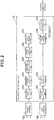
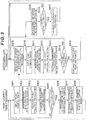
- Fig. 2 is a block diagram illustrating an internal configuration of the calibration apparatus 110 illustrated in Fig. 1 ; and Fig. 3 is a flowchart for explaining a processing flow by the calibration apparatus 110 illustrated in Fig. 1 .
- the calibration apparatus 110 is basically configured by including: a feature point detection unit (a first feature point detection unit) 201 that detects feature points (first feature points) from images captured by the front camera 102; a feature point detection unit (a second feature point detection unit) 202 that detects feature points (second feature points) from images captured by the side camera 106 (the left-side camera 104 or the right-side camera 105); a feature point tracking unit (a first feature point tracking unit) 203 that tracks the feature points in the images captured by the front camera 102; a feature point tracking unit (a second feature point tracking unit) 204 that tracks the feature points in the images captured by the side camera 106; a feature point height calculation unit 205 that calculates the heights of the feature points in the images captured by the front camera 102; a road surface range estimation unit 206 by the front camera 102; a road surface range setting unit 207 that determines a feature point range (that is, the road surface range) to be adopted for the calibration of the side camera 106
- the feature point detection unit 201 on the front camera 102 side and the feature point detection unit 202 on the side camera 106 side may be shared and the feature point tracking unit 203 on the front camera 102 side and the feature point tracking unit 204 on the side camera 106 side may be shared.
- the feature points herein used mean places (points) which can easily be identified as the same points in a plurality of images, and include, for example, corner points of the road surface paint. This feature point detection processing is executed by using known detection technology.
- Coordinates of the feature points detected by the feature point detection unit 201 are sent to the feature point tracking unit 203.
- the feature point tracking unit 203 tracks the same feature point from images captured by the front camera 102 at different times of day (time-series images) (S303 in Fig. 3 ). This feature point tracking processing over the plurality of times of day is executed by using known tracking technology.
- the coordinates of the obtained feature points are saved (S304 in Fig. 3 ) and also sent to the feature point height calculation unit 205.
- the feature point height calculation unit 205 judges whether the number of the obtained feature points (that is, a saved quantity) has reached a predetermined specified quantity or not (S305 in Fig. 3 ); and if the saved quantity has reached the specified quantity, the coordinates of the feature points undergo bird's-eye view transformation and are transformed to coordinates on the road surface.
- the feature point height calculation unit 205 calculates the height of the relevant feature point from a moved distance or a moving speed of the coordinates on the road surface on the basis of a vehicle speed obtained from a vehicle speed sensor or a wheel speed sensor mounted on the vehicle 101 (S306 in Fig. 3 ); judges whether the relevant feature point truly exists on the road surface or not (in other words, whether the feature point has the same height as that of the road surface or not); and sends the judgment result to the road surface range estimation unit 206.
- the detection of the feature points by the feature point detection unit 201 and the tracking of the feature points by the feature point tracking unit 203 are performed not only once, but continuously every time an image is input from the front camera 102 as described earlier.
- the judgment results of the feature points detected and tracked during a certain period of time are accumulated in the road surface range estimation unit 206.
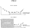
- the road surface range estimation unit 206 estimates that a distribution range of the feature points which are judged from the above results to be located on the road surface (that is, the feature points having the same height as that of the road surface) is on the road surface (the road surface range) (S307 in Fig. 3 )(see an upper diagram of Fig. 4 ).
- the estimation result by the road surface range estimation unit 206 is sent to the road surface range setting unit 207 and the side camera 106 side is informed to that effect (S308 in Fig. 3 ); and the road surface range setting unit 207 determines (sets) a range to be judged as the road surface on the side camera 106 side (S309 in Fig. 3 ).
- the side camera 106 is in a state before the calibration, so that an error occurs in the coordinates after the bird's-eye view transformation and, therefore, the road surface range is set in consideration of an error range.
- the range is usually set by removing a certain proportion or a certain length from an edge of the road surface range (see a lower diagram of Fig. 4 ).
- the setting of the road surface range by this road surface range setting unit 207 is updated periodically.
- the feature points are detected and tracked in the same manner as with the front camera 102.
- This feature point detection processing is similar to the detecting method executed by the feature point detection unit 201 on the front camera 102 side.
- Coordinates of the feature points detected by the feature point detection unit 202 are sent to the feature point tracking unit 204.
- the feature point tracking unit 204 tracks the same feature point from images captured by the side camera 106 at different times of day (S312 in Fig. 3 ).
- the tracking processing by this feature point tracking unit 204 is also similar to the tracking processing executed by the feature point tracking unit 203 on the front camera 102 side.
- the coordinates of the feature points regarding which the tracking by the feature point tracking unit 204 is completed are sent to the feature point sorting unit 208.
- the feature point sorting unit 208 extracts the coordinates of the feature point, which are then transformed to coordinates in a bird's-eye image (S313 in Fig. 3 ). Furthermore, the feature point sorting unit 208: judges whether or not the coordinates in this bird's-eye image match the road surface range which is sent from the road surface range setting unit 207 (that is, whether such coordinates exist within the road surface range or not) (S314 in Fig.
- the calibration operation unit 209 judges whether the number of the feature points sorted out and saved by the feature point sorting unit 208 (the feature points within the road surface range) (that is, a saved quantity) has reached a predetermined specified quantity or not (S316 in Fig. 3 ); and if the saved quantity has reached the specified quantity, the calibration operation unit 209 performs the calibration of the side camera 106 by using the feature points (the feature points within the road surface range) (S317 in Fig. 3 ).
- the calibration operation processing by this calibration operation unit 209 is executed in accordance with the following procedures.
- the moved distance of the feature point matches a travel distance of the vehicle 101 in the bird's-eye view coordinates. Moreover, if the vehicle 101 is moving straight ahead, the feature point moves straight backwards. If there is an error in the pitch angle of the side camera 106, the feature point moves obliquely or the moved distance of the feature point becomes different from the moved distance of the vehicle 101. If an angle used for the bird's-eye view transformation is changed by a minute amount, the position of the feature point at the bird's-eye view coordinates changes, so that the moving direction and the moved distance of the feature point change.
- pitch angle of the side camera 106 changes, mainly the moved distance of the feature point changes. Therefore, if the pitch angle used for the calculation to execute the bird's-eye view transformation processing is changed by minute amounts and an angle to make the moved distance of the feature point match the moved distance of the vehicle 101 is thereby found, that pitch angle can be estimated as a right pitch angle.
- the calibration of the side camera 106 can be performed by finding the difference between the moved distance of each feature point and the moved distance of the vehicle 101, recognizing the total sum of such absolute values or the total sum of squared errors as an evaluation value, and finding a pitch angle which makes the evaluation value minimum.
- the above-described calculation of the calibration can be performed only once, but the precision can be enhanced by repeatedly executing the calculation. This can be implemented by feeding back the first calibration result of the calibration operation unit 209 to the feature point sorting unit 208.
- the feature point sorting unit 208 it is necessary to transform the coordinates of the feature points to the bird's-eye view coordinates before sorting out the feature points as described earlier; however, if the calibration has never been performed, for example, a design value is used. Since this angle includes a large error, there is a possibility that the feature point(s) may be mistakenly selected due to the influence of the error when sorting out the feature points. Specifically speaking, a feature point(s) which exists on the road surface, but is located close to the edge of the road surface may sometimes be removed during the sorting; or a feature point(s) which is located out of the road surface, but close to the road surface may sometimes be mistakenly selected. Such selection mistakes may cause an error in the calibration result of the calibration operation unit 209.
- the second calibration is performed by feeding back the calibration result of the calibration operation unit 209 to the feature point sorting unit 208 and sorting out the feature points again.
- the newly obtained feature points are sorted out by making them undergo the bird's-eye view transformation with the angle after the feedback. As a result, a higher-precision result can be obtained by the second calibration.
- the calibration result with much higher precision can be obtained by repeating the above-described calibration and the feedback.
- the calibration operation unit 209 After repeating the calibration a certain number of times or during a certain period of time in the above-described manner, the calibration operation unit 209 outputs the last calibration result.
- the above-described embodiment has described the operation on the premise that the front camera 102 exists; however, if the front camera 102 does not exist, similar operation can be performed by using the rear camera 103.
- the front camera 102 for monitoring the area in front of the vehicle is indispensable; however, if only assistance of the driver's driving is assumed and in a case of an in-vehicle camera system equipped with only the rear camera 103 for monitoring the area behind the vehicle, which is a blind area for the driver, and the side camera(s) 106 (the left-side camera 104 and/or the right-side camera 105) for monitoring areas on the lateral sides of the vehicle, the calibration similar to that of the above-described embodiment can be implemented by using the rear camera 103.
- a plurality of side cameras 106 normally exist.
- the calibration of the plurality of side cameras can be performed at the same time by conducting the road surface range judgment by using images captured by the front camera 102 and transferring the road surface range estimation result to each of the plurality of side cameras.
- a camera for which the road surface range is invisible in the image can be selected based on the road surface range estimation by using the image captured by the front camera 102.
- some extra processing capacity is produced by stopping the processing of the camera for which the road surface area is invisible, it is also possible to further enhance safety by, for example, using that processing capacity for the calibration of other cameras or distributing that processing capacity to other processing such as calculation for the automatic driving.
- the calibration apparatus 110 executes the calibration by estimating the road surface range by using feature points appearing in an image(s) captured by a camera (the front camera 102 or the rear camera 103) that is not a camera for which the calibration is executed (the side camera 106), and by using only feature points existing within the estimated road surface range from among the feature points appearing in the image(s) captured by the camera for which the calibration is executed; and, therefore, regarding the calibration of the side camera 106 in a scene where many feature points are captured on, for example, a wall surface other than the road surface, a high-precision calibration result can be obtained by appropriately taking out only the feature points on the road surface. As a result, it is possible to enhance the safety of, for example, the automatic driving by using the images captured by each camera.
- the present invention is not limited to the aforementioned embodiment, and includes various variations.
- the aforementioned embodiment has been described in detail in order to explain the invention in an easily comprehensible manner and is not necessarily limited to the embodiment having all the configurations explained above.
- each of the aforementioned configurations, functions, processing units, processing means, etc. may be implemented by hardware by, for example, designing part or all of such configurations, functions, processing units, and processing means by using integrated circuits or the like.
- each of the aforementioned configurations, functions, etc. may be realized by software by processors interpreting and executing programs for realizing each of the functions. Information such as programs, tables, and files for realizing each of the functions may be retained in memories, storage devices such as hard disks and SSDs (Solid State Drives), or storage media such as IC cards, SD cards, and DVDs.
- control lines and information lines which are considered to be necessary for the explanation are illustrated; however, not all control lines or information lines are necessarily indicated in terms of products. Practically, it may be assumed that almost all components are connected to each other.
Landscapes
- Engineering & Computer Science (AREA)
- Physics & Mathematics (AREA)
- General Physics & Mathematics (AREA)
- Theoretical Computer Science (AREA)
- Computer Vision & Pattern Recognition (AREA)
- Multimedia (AREA)
- Signal Processing (AREA)
- Health & Medical Sciences (AREA)
- Biomedical Technology (AREA)
- General Health & Medical Sciences (AREA)
- Image Analysis (AREA)
- Image Processing (AREA)
- Closed-Circuit Television Systems (AREA)
- Studio Devices (AREA)
- Traffic Control Systems (AREA)
Abstract
Description
- The present invention relates to a calibration apparatus and method for automatically calibrating external parameters of an in-vehicle camera.
- In recent years, vehicle control such as automatic parking and automatic driving by using an in-vehicle camera(s) (hereinafter sometimes simply referred to as the camera(s)) which are mounted in a vehicle such as an automobile has been under consideration. In order to control the vehicle by using images captured by the camera, it is necessary to find external parameters such as a mounting position and a mounting angle of the camera precisely; however, physical mounting precision is not enough to perform the vehicle control.
- Also, when loads such as humans who get on the vehicle and baggage loaded into the vehicle change, the vehicle body moves up or down or an inclination of the vehicle body changes. Accordingly, the position of the camera changes and the inclination or direction of the camera changes.
- According to the conventional technology, the external parameter(s) of the camera is found by mounting the camera at the vehicle and measuring then the external parameter(s) at a measurement location with a floor face to which an already-known pattern is applied; however, in order to carry out such a method, it is necessary to mount the camera at the vehicle and then carry the vehicle with the camera mounted thereon into the measurement location and, therefore, it requires heavy workload. Additionally, the above-described method cannot deal with any change of the external parameter caused by the change of the loads on the vehicle.
- Therefore, a method for calibrating the external parameters of the camera while the vehicle is running has come to be used.
- As the method for calibrating the external parameters of the in-vehicle camera while the vehicle is running,
PTL 1 mentioned below proposes a method for tracking a plurality of detected feature points in images, which are input from a camera, and estimating the external parameters of the camera from time-series coordinate positions of the feature points. - PTL 1 :
WO2012/139636 - Meanwhile, the above-mentioned method described in
PTL 1 is on the premise that the feature points to be used are on the same height as that of the road surface such as road surface paint. However, the feature points appearing in a camera image are not always located at the same height as that of the road surface and the feature points such as walls, guard rails, and surrounding houses are also captured; and if the calibration is performed by using these feature points, misalignment may be caused in the calibration result. Furthermore, particularly regarding a side camera which is installed on a side face of the vehicle and captures images of an area on a lateral side of the vehicle, in a case where feature points with different heights are aligned and in a case where a pitch angle of the camera is misaligned, the feature points appear to follow similar tracks, which results in the problem of difficulty in distinguishing the above-described cases from one another. - For example, in the environment of the vehicle illustrated in
Fig. 6 , the in-vehicle camera detects and tracks not only feature points on the road surface, but also feature points appearing on a wall. Particularly regarding the side camera which is installed on the side face of the vehicle body, the wall appears in most of its visual field range, so that many feature points on the wall surface will be obtained (see particularly an upper diagram inFig. 6 ). When these obtained feature points are mapped onto a bird's-eye image (an image of the vehicle as if it were looked down directly from above), points at which straight lines connecting the camera and the feature points intersect with the road surface are treated as feature points. Since these feature points are recognized to move on the road surface as illustrated in a lower diagram inFig. 6 , they are observed as if they were moving at faster speeds than the vehicle's speed. If a plurality of feature points with different heights exist on the wall surface, they are observed as having different apparent moving speeds due to their positions (heights). If the calibration is performed based on the movements of these feature points, the same situation as the misalignment of the pitch angle of the side camera occurs, so that the calibration result which is different from the original pitch angle will be obtained. - Therefore, when performing the calibration of the camera, it is necessary to exclude the feature points having heights from the road surface; however, in the environment illustrated in
Fig. 6 , both the pitch angle misalignment and the feature points having the heights show apparently the same movements, so that they cannot be distinguished one from another. - The present invention was devised in light of the above-described circumstances and it is an object of the invention to provide a calibration apparatus and method capable of taking out only feature points on the road surface from an image captured by an in-vehicle camera, which is a calibration target, and obtaining a high-precision calibration result.
- In order to solve the above-described problems, a camera calibration apparatus according to the present invention is a calibration apparatus for executing calibration of an external parameter for a plurality of in-vehicle cameras in an in-vehicle camera system waiting for input from the plurality of in-vehicle cameras, wherein a road surface range is estimated by using a feature points appearing in an image captured by one or more in-vehicle cameras that are not an in-vehicle camera on which the calibration is executed; and wherein the calibration is executed by using only a feature points existing within the estimated road surface range from among feature points appearing in an image captured by the in-vehicle camera on which the calibration is executed.
- Furthermore, a camera calibration apparatus according to the present invention is a calibration apparatus for executing calibration of an external parameter for a plurality of in-vehicle cameras in an in-vehicle camera system having input from the plurality of in-vehicle cameras, the calibration apparatus comprising: a first feature point detection unit that detects first feature points appearing in an image captured by a calibration nontarget in-vehicle camera that is not a calibration target in-vehicle camera on which the calibration is executed; a first feature point tracking unit that tracks the first feature points from images captured by the calibration nontarget in-vehicle camera at different times of day; a feature point height calculation unit that calculates a height of each of the first feature points from a moved distance or a moving speed of the tracked first feature point; a road surface range estimation unit that estimates, as a road surface range, a range where the first feature point having the same height as that of a road surface exists, from among the first feature points; a road surface range setting unit that sets the estimated road surface range as a road surface range for the calibration target in-vehicle camera; a second feature point detection unit that detects second feature points appearing in an image captured by the calibration target in-vehicle camera on which the calibration is executed; a second feature point tracking unit that tracks the second feature points from images captured by the calibration target in-vehicle camera at different times of day; a feature point sorting unit that sorts out the second feature points existing within the road surface range from the tracked second feature points; and a calibration operation unit that executes the calibration of the calibration target in-vehicle camera from only the second feature points existing within the road surface range.
- Furthermore, a camera calibration method according to the present invention is a calibration method for executing calibration of an external parameters for a plurality of in-vehicle cameras in an in-vehicle camera system waiting for input from the plurality of in-vehicle cameras, wherein a road surface range is estimated by using a feature point appearing in an image captured by one or more in-vehicle cameras that are not an in-vehicle camera on which the calibration is executed; and wherein the calibration is executed by using only a feature point existing within the estimated road surface range from among feature points appearing in an image captured by the in-vehicle camera on which the calibration is executed.
- Regarding the calibration of the side camera in a scene where many feature points can be captured on, for example, a wall surface other than the road surface, a high-precision calibration result can be obtained according to the present invention by appropriately taking out only the feature points on the road surface. Consequently, it becomes possible to enhance safety of, for example, automatic driving using the images captured by the in-vehicle camera(s).
- The problems, configurations, and advantageous effects other than those described above will become clear from the description of the embodiments below.
-
-
Fig. 1 is an outline configuration diagram illustrating a system configuration of an in-vehicle camera system to which an embodiment of a calibration apparatus according to the present invention is applied; -
Fig. 2 is a block diagram illustrating an internal configuration of an embodiment of the calibration apparatus according to the present invention; -
Fig. 3 is a flowchart for explaining a processing flow of an embodiment of the calibration apparatus according to the present invention; -
Fig. 4 is a diagram for explaining an example of processing by a road surface range estimation unit and a road surface range setting unit; -
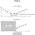
Fig. 5 is a diagram for explaining another example of processing by the road surface range estimation unit and the road surface range setting unit; and -
Fig. 6 is a diagram illustrating an example of an ambient environment of a vehicle and feature points appearing in images captured by an in-vehicle camera. - An embodiment of the present invention will be explained below in detail with reference to the drawings.
-
Fig. 1 is an outline configuration diagram illustrating a system configuration of an in-vehicle camera system to which an embodiment of a calibration apparatus according to the present invention is applied. - In the embodiment illustrated in the drawing, four
cameras 102 to 105 are mounted on avehicle 101 and are installed at, for example, the front side, the rear side, the right side, and the left side of a vehicle body of thevehicle 101. Afront camera 102 which is installed on a front face of the vehicle body of thevehicle 101 captures and generates images of an area in front of the vehicle body; arear camera 103 which is installed on a rear face of the vehicle body of thevehicle 101 captures and generates images of an area behind the vehicle body; a left-side camera 104 which is installed on a left side face of the vehicle body of thevehicle 101 captures and generates images of an area on the left side of the vehicle body; and a right-side camera 105 which is installed on a right side face of the vehicle body of thevehicle 101 captures and generates images of an area on the right side of the vehicle body. Eachcamera 102 to 105 is usually mounted in a manner such that an optical axis will face a direction extending from in parallel with a horizontal plane, which is parallel to the road surface (ground), to vertically below the horizontal plane. Also, for example, a wide angle fish-eye camera is adopted for eachcamera 102 to 105 so that images of the entire surrounding area around thevehicle 101 can be obtained. - Incidentally, it is a matter of course that the number of the cameras mounted on the
vehicle 101 and their positions, etc. are not limited to those in the example illustrated in the drawing. - The
vehicle 101 is equipped with an ECU 107 as a processing apparatus for receiving and processing the images captured by eachcamera 102 to 105. ThisECU 107 is composed of a microcomputer including: a CPU as an arithmetic unit for performing various kinds of arithmetic operation processing based on programs and so on; a RAM storing image data captured by eachcamera 102 to 105; and a ROM storing programs for executing various kinds of arithmetic operation processing (for example, the calibration of external parameters for the cameras as described later) and information required for the programs. - In this embodiment, the above-described ECU 107 has a
calibration apparatus 110 built in for automatically calibrating the external parameters for eachcamera 102 to 105 by using the images captured by eachcamera 102 to 105, for example, while thevehicle 101 is running. - When performing the calibration of each
camera 102 to 105 as described earlier, it is necessary to exclude the feature points having heights from the road surface such as walls, guard rails, and surrounding houses from the feature points appearing in the images captured by thecamera 102 to 105 which is a calibration target. In order to solve this, information (images) of thefront camera 102 capable of photographing the area in front of the vehicle body is used in this embodiment. The same can be performed even when using information (images) of therear camera 103 capable of photographing the area behind the vehicle body; however, in this embodiment, the following explanation will be provided regarding the operation using the information (images) of thefront camera 102. - The
front camera 102 has acquired feature points in front of the vehicle body and, in most cases except when making a turn, is capable of capturing the road surface in a traveling direction of thevehicle 101 while thevehicle 101 is running. When the calibration of thefront camera 102 is correct, the feature points on the road surface move backwards at the same speed as the vehicle speed of thevehicle 101 in a bird's-eye image, while the feature points on, for example, a wall surface, whose heights are at positions different from that of the road surface are recognized as moving at faster speeds than the vehicle speed of thevehicle 101 as described earlier. - Specifically speaking, regarding the
front camera 102, the calibration of a camera angle can be performed by using only the feature points on the road surface in front of the vehicle body (the feature points detected in images captured by the front camera 102). Also, the road surface range can be estimated from moved distances and moving speeds of the feature points after the calibration (as described later in detail). - Meanwhile, the left-
side camera 104 and the right-side camera 105 acquire feature points in areas on lateral sides of the vehicle body and tend to acquire many feature points, for example, on a wall surface, which have heights located at positions different from the height of the road surface. Therefore, this embodiment is designed to perform the calibration of the camera angle by using the information (images) of thefront camera 102, excluding and discarding the above-described feature points (the feature points with heights located at positions different from the height of the road surface) from the feature points appearing in the images captured by the left-side camera 104 and the right-side camera 105, and selecting only the feature points on the road surface. - Incidentally, when the
vehicle 101 making a turn, the area in front of the vehicle body may not always be the road surface; however, turning of thevehicle 101 can be detected by acquiring vehicle information such as a steering angle of a steering wheel, so that in that case, it is possible to deal with the situation by stopping the acquisition of the feature points. - The details of the calibration by the
calibration apparatus 110 according to this embodiment described above, particularly, the details of the calibration of the left-side camera 104 or the right-side camera 105 by thecalibration apparatus 110 will be explained by usingFigs. 2 and3 .Fig. 2 is a block diagram illustrating an internal configuration of thecalibration apparatus 110 illustrated inFig. 1 ; andFig. 3 is a flowchart for explaining a processing flow by thecalibration apparatus 110 illustrated inFig. 1 . - Referring to
Fig. 2 , thecalibration apparatus 110 is basically configured by including: a feature point detection unit (a first feature point detection unit) 201 that detects feature points (first feature points) from images captured by thefront camera 102; a feature point detection unit (a second feature point detection unit) 202 that detects feature points (second feature points) from images captured by the side camera 106 (the left-side camera 104 or the right-side camera 105); a feature point tracking unit (a first feature point tracking unit) 203 that tracks the feature points in the images captured by thefront camera 102; a feature point tracking unit (a second feature point tracking unit) 204 that tracks the feature points in the images captured by theside camera 106; a feature pointheight calculation unit 205 that calculates the heights of the feature points in the images captured by thefront camera 102; a road surfacerange estimation unit 206 by thefront camera 102; a road surfacerange setting unit 207 that determines a feature point range (that is, the road surface range) to be adopted for the calibration of theside camera 106; a featurepoint sorting unit 208 that sorts out the feature points to be adopted for the calibration of theside camera 106; and a calibration operation unit 209 that executes the calibration of the side camera. - Incidentally, needless to provide any detailed explanation, regarding the above-described
calibration apparatus 110, the featurepoint detection unit 201 on thefront camera 102 side and the featurepoint detection unit 202 on theside camera 106 side may be shared and the featurepoint tracking unit 203 on thefront camera 102 side and the featurepoint tracking unit 204 on theside camera 106 side may be shared. - The above-described
calibration apparatus 110 executes processing on thefront camera 102 side and processing on theside camera 106 side almost at the same time; however, in the following explanation, the operation on thefront camera 102 side will be firstly explained. - After an image is input from the
front camera 102 to the calibration apparatus 110 (S301 inFig. 3 ), that image is input to the featurepoint detection unit 201 and feature points are extracted (detected) from that image (S302 inFig. 3 ). The feature points herein used mean places (points) which can easily be identified as the same points in a plurality of images, and include, for example, corner points of the road surface paint. This feature point detection processing is executed by using known detection technology. - Coordinates of the feature points detected by the feature
point detection unit 201 are sent to the featurepoint tracking unit 203. The featurepoint tracking unit 203 tracks the same feature point from images captured by thefront camera 102 at different times of day (time-series images) (S303 inFig. 3 ). This feature point tracking processing over the plurality of times of day is executed by using known tracking technology. - After the tracking by the feature
point tracking unit 203 is completed, the coordinates of the obtained feature points (tracking-completed feature points) are saved (S304 inFig. 3 ) and also sent to the feature pointheight calculation unit 205. The feature pointheight calculation unit 205 judges whether the number of the obtained feature points (that is, a saved quantity) has reached a predetermined specified quantity or not (S305 inFig. 3 ); and if the saved quantity has reached the specified quantity, the coordinates of the feature points undergo bird's-eye view transformation and are transformed to coordinates on the road surface. Furthermore, the feature point height calculation unit 205: calculates the height of the relevant feature point from a moved distance or a moving speed of the coordinates on the road surface on the basis of a vehicle speed obtained from a vehicle speed sensor or a wheel speed sensor mounted on the vehicle 101 (S306 inFig. 3 ); judges whether the relevant feature point truly exists on the road surface or not (in other words, whether the feature point has the same height as that of the road surface or not); and sends the judgment result to the road surfacerange estimation unit 206. - The detection of the feature points by the feature
point detection unit 201 and the tracking of the feature points by the featurepoint tracking unit 203 are performed not only once, but continuously every time an image is input from thefront camera 102 as described earlier. The judgment results of the feature points detected and tracked during a certain period of time (the judgment results by the feature point height calculation unit 205) are accumulated in the road surfacerange estimation unit 206. The road surfacerange estimation unit 206 estimates that a distribution range of the feature points which are judged from the above results to be located on the road surface (that is, the feature points having the same height as that of the road surface) is on the road surface (the road surface range) (S307 inFig. 3 )(see an upper diagram ofFig. 4 ). - The estimation result by the road surface
range estimation unit 206 is sent to the road surfacerange setting unit 207 and theside camera 106 side is informed to that effect (S308 inFig. 3 ); and the road surfacerange setting unit 207 determines (sets) a range to be judged as the road surface on theside camera 106 side (S309 inFig. 3 ). Under this circumstance, theside camera 106 is in a state before the calibration, so that an error occurs in the coordinates after the bird's-eye view transformation and, therefore, the road surface range is set in consideration of an error range. Specifically speaking, since a wide-angle fish-angle camera is usually adopted for therelevant side camera 106 and an invisible area exists in therelevant side camera 106, the range is usually set by removing a certain proportion or a certain length from an edge of the road surface range (see a lower diagram ofFig. 4 ). - The setting of the road surface range by this road surface
range setting unit 207 is updated periodically. - Next, the operation of the
side camera 106 side will be explained. - Regarding the
side camera 106, the feature points are detected and tracked in the same manner as with thefront camera 102. - After an image is input from the
side camera 106 to the calibration apparatus 110 (S310 inFig. 3 ), that image is input to the featurepoint detection unit 202 and feature points are detected from that image (S311 inFig. 3 ). This feature point detection processing is similar to the detecting method executed by the featurepoint detection unit 201 on thefront camera 102 side. - Coordinates of the feature points detected by the feature
point detection unit 202 are sent to the featurepoint tracking unit 204. The featurepoint tracking unit 204 tracks the same feature point from images captured by theside camera 106 at different times of day (S312 inFig. 3 ). The tracking processing by this featurepoint tracking unit 204 is also similar to the tracking processing executed by the featurepoint tracking unit 203 on thefront camera 102 side. - The coordinates of the feature points regarding which the tracking by the feature
point tracking unit 204 is completed (tracking-completed feature points) are sent to the featurepoint sorting unit 208. The featurepoint sorting unit 208 extracts the coordinates of the feature point, which are then transformed to coordinates in a bird's-eye image (S313 inFig. 3 ). Furthermore, the feature point sorting unit 208: judges whether or not the coordinates in this bird's-eye image match the road surface range which is sent from the road surface range setting unit 207 (that is, whether such coordinates exist within the road surface range or not) (S314 inFig. 3 ); and sorts out only the coordinates within the road surface range (the feature points having such coordinates) and sends them to, and saves them in, the calibration operation unit 209 (S315 inFig. 3 ). Incidentally, the feature points which are determined to not exist within the road surface range are discarded (S318 inFig. 3 ). - The calibration operation unit 209 judges whether the number of the feature points sorted out and saved by the feature point sorting unit 208 (the feature points within the road surface range) (that is, a saved quantity) has reached a predetermined specified quantity or not (S316 in
Fig. 3 ); and if the saved quantity has reached the specified quantity, the calibration operation unit 209 performs the calibration of theside camera 106 by using the feature points (the feature points within the road surface range) (S317 inFig. 3 ). The calibration operation processing by this calibration operation unit 209 is executed in accordance with the following procedures. - Specifically speaking, when the calibration is performed correctly, the moved distance of the feature point matches a travel distance of the
vehicle 101 in the bird's-eye view coordinates. Moreover, if thevehicle 101 is moving straight ahead, the feature point moves straight backwards. If there is an error in the pitch angle of theside camera 106, the feature point moves obliquely or the moved distance of the feature point becomes different from the moved distance of thevehicle 101. If an angle used for the bird's-eye view transformation is changed by a minute amount, the position of the feature point at the bird's-eye view coordinates changes, so that the moving direction and the moved distance of the feature point change. - If the pitch angle of the
side camera 106 changes, mainly the moved distance of the feature point changes. Therefore, if the pitch angle used for the calculation to execute the bird's-eye view transformation processing is changed by minute amounts and an angle to make the moved distance of the feature point match the moved distance of thevehicle 101 is thereby found, that pitch angle can be estimated as a right pitch angle. - Furthermore, if not only one feature point, but a plurality of feature points exist which are detected and tracked in images captured by the
side camera 106, the calibration of theside camera 106 can be performed by finding the difference between the moved distance of each feature point and the moved distance of thevehicle 101, recognizing the total sum of such absolute values or the total sum of squared errors as an evaluation value, and finding a pitch angle which makes the evaluation value minimum. - The above-described calculation of the calibration can be performed only once, but the precision can be enhanced by repeatedly executing the calculation. This can be implemented by feeding back the first calibration result of the calibration operation unit 209 to the feature
point sorting unit 208. - With the feature
point sorting unit 208, it is necessary to transform the coordinates of the feature points to the bird's-eye view coordinates before sorting out the feature points as described earlier; however, if the calibration has never been performed, for example, a design value is used. Since this angle includes a large error, there is a possibility that the feature point(s) may be mistakenly selected due to the influence of the error when sorting out the feature points. Specifically speaking, a feature point(s) which exists on the road surface, but is located close to the edge of the road surface may sometimes be removed during the sorting; or a feature point(s) which is located out of the road surface, but close to the road surface may sometimes be mistakenly selected. Such selection mistakes may cause an error in the calibration result of the calibration operation unit 209. - Even if the error is caused in the calibration result of the calibration operation unit 209, its reliability is higher than angle information before the calibration. Therefore, it is possible to reduce the selection mistake by using the angle of the calibration result of the calibration operation unit 209 for the bird's-eye view transformation for sorting out the feature points of the feature
point sorting unit 208. - Specifically speaking, the second calibration is performed by feeding back the calibration result of the calibration operation unit 209 to the feature
point sorting unit 208 and sorting out the feature points again. Alternatively, the newly obtained feature points are sorted out by making them undergo the bird's-eye view transformation with the angle after the feedback. As a result, a higher-precision result can be obtained by the second calibration. - The calibration result with much higher precision can be obtained by repeating the above-described calibration and the feedback.
- After repeating the calibration a certain number of times or during a certain period of time in the above-described manner, the calibration operation unit 209 outputs the last calibration result.
- Incidentally, the above-described embodiment has described the operation on the premise that the
front camera 102 exists; however, if thefront camera 102 does not exist, similar operation can be performed by using therear camera 103. If automatic driving based on images captured by the camera(s) is assumed, thefront camera 102 for monitoring the area in front of the vehicle is indispensable; however, if only assistance of the driver's driving is assumed and in a case of an in-vehicle camera system equipped with only therear camera 103 for monitoring the area behind the vehicle, which is a blind area for the driver, and the side camera(s) 106 (the left-side camera 104 and/or the right-side camera 105) for monitoring areas on the lateral sides of the vehicle, the calibration similar to that of the above-described embodiment can be implemented by using therear camera 103. - Furthermore, a plurality of
side cameras 106 normally exist. In this case as well, the calibration of the plurality of side cameras can be performed at the same time by conducting the road surface range judgment by using images captured by thefront camera 102 and transferring the road surface range estimation result to each of the plurality of side cameras. Incidentally, for the purpose of reduction of the loadage of theECU 107 as an arithmetic unit or for the purpose of reduction of the power consumption, it is also possible to execute the calibration of the plurality of side cameras sequentially, but not at the same time. - Furthermore, a camera for which the road surface range is invisible in the image (see
Fig. 5 ) can be selected based on the road surface range estimation by using the image captured by thefront camera 102. In this case, it is possible to reduce the throughput and reduce the power consumption by stopping the entire processing of the camera for which the road surface area is invisible. Furthermore, some extra processing capacity is produced by stopping the processing of the camera for which the road surface area is invisible, it is also possible to further enhance safety by, for example, using that processing capacity for the calibration of other cameras or distributing that processing capacity to other processing such as calculation for the automatic driving. - The
calibration apparatus 110 according to this embodiment as explained above executes the calibration by estimating the road surface range by using feature points appearing in an image(s) captured by a camera (thefront camera 102 or the rear camera 103) that is not a camera for which the calibration is executed (the side camera 106), and by using only feature points existing within the estimated road surface range from among the feature points appearing in the image(s) captured by the camera for which the calibration is executed; and, therefore, regarding the calibration of theside camera 106 in a scene where many feature points are captured on, for example, a wall surface other than the road surface, a high-precision calibration result can be obtained by appropriately taking out only the feature points on the road surface. As a result, it is possible to enhance the safety of, for example, the automatic driving by using the images captured by each camera. - Incidentally, the present invention is not limited to the aforementioned embodiment, and includes various variations. For example, the aforementioned embodiment has been described in detail in order to explain the invention in an easily comprehensible manner and is not necessarily limited to the embodiment having all the configurations explained above.
- Furthermore, each of the aforementioned configurations, functions, processing units, processing means, etc. may be implemented by hardware by, for example, designing part or all of such configurations, functions, processing units, and processing means by using integrated circuits or the like. Moreover, each of the aforementioned configurations, functions, etc. may be realized by software by processors interpreting and executing programs for realizing each of the functions. Information such as programs, tables, and files for realizing each of the functions may be retained in memories, storage devices such as hard disks and SSDs (Solid State Drives), or storage media such as IC cards, SD cards, and DVDs.
- Furthermore, control lines and information lines which are considered to be necessary for the explanation are illustrated; however, not all control lines or information lines are necessarily indicated in terms of products. Practically, it may be assumed that almost all components are connected to each other.
-
- 101:
- vehicle
- 102:
- front camera
- 103:
- rear camera
- 104:
- left-side camera
- 105:
- right-side camera
- 106:
- side camera
- 107:
- ECU
- 110:
- calibration apparatus
- 201:
- feature point detection unit (first feature point detection unit)
- 202:
- feature point detection unit (second feature point detection unit)
- 203:
- feature point tracking unit (first feature point tracking unit)
- 204:
- feature point tracking unit (second feature point tracking unit)
- 205:
- feature point height calculation unit
- 206:
- road surface range estimation unit
- 207:
- road surface range setting unit
- 208:
- feature point sorting unit
- 209:
- calibration operation unit
Claims (9)
- A calibration apparatus for executing calibration of an external parameter for a plurality of in-vehicle cameras in an in-vehicle camera system having input from the plurality of in-vehicle cameras,
wherein a road surface range is estimated by using a feature point appearing in an image captured by one or more in-vehicle cameras that are not an in-vehicle camera on which the calibration is executed; and
wherein the calibration is executed by using only a feature point existing within the estimated road surface range from among feature points appearing in an image captured by the in-vehicle camera on which the calibration is executed. - The calibration apparatus according to claim 1,
wherein the road surface range is estimated based on a moved distance or a moving speed of the feature point appearing in the image captured by the one or more in-vehicle cameras that are not the in-vehicle camera on which the calibration is executed. - The calibration apparatus according to claim 1,
wherein the in-vehicle camera that is not the in-vehicle camera on which the calibration is executed is a front camera for capturing images of an area in front of a vehicle or a rear camera for capturing images of an area behind the vehicle. - The calibration apparatus according to claim 1,
wherein the in-vehicle camera on which the calibration is executed is a side camera for capturing images of an area on a lateral side of the vehicle. - A calibration apparatus for executing calibration of an external parameter for a plurality of in-vehicle cameras in an in-vehicle camera system having input from the plurality of in-vehicle cameras,
the calibration apparatus comprising:a first feature point detection unit that detects first feature points appearing in an image captured by a calibration nontarget in-vehicle camera that is not a calibration target in-vehicle camera on which the calibration is executed;a first feature point tracking unit that tracks the first feature points from images captured by the calibration nontarget in-vehicle camera at different times of day;a feature point height calculation unit that calculates a height of each of the first feature points from a moved distance or a moving speed of the tracked first feature point;a road surface range estimation unit that estimates, as a road surface range, a range where the first feature point having the same height as that of a road surface exists, from among the first feature points;a road surface range setting unit that sets the estimated road surface range as a road surface range for the calibration target in-vehicle camera;a second feature point detection unit that detects second feature points appearing in an image captured by the calibration target in-vehicle camera on which the calibration is executed;a second feature point tracking unit that tracks the second feature points from images captured by the calibration target in-vehicle camera at different times of day;a feature point sorting unit that sorts out the second feature points existing within the road surface range from the tracked second feature points; anda calibration operation unit that executes the calibration of the calibration target in-vehicle camera from only the second feature points existing within the road surface range. - A calibration method for executing calibration of an external parameter for a plurality of in-vehicle cameras in an in-vehicle camera system having input from the plurality of in-vehicle cameras,
wherein a road surface range is estimated by using a feature point appearing in an image captured by one or more in-vehicle cameras that are not an in-vehicle camera on which the calibration is executed; and
wherein the calibration is executed by using only a feature point existing within the estimated road surface range from among feature points appearing in an image captured by the in-vehicle camera on which the calibration is executed. - The calibration method according to claim 6,
wherein the road surface range is estimated based on a moved distance or a moving speed of the feature point appearing in the image captured by the one or more in-vehicle cameras that are not the in-vehicle camera on which the calibration is executed. - The calibration method according to claim 6,
wherein the in-vehicle camera that is not the in-vehicle camera on which the calibration is executed is a front camera for capturing images of an area in front of a vehicle or a rear camera for capturing images of an area behind the vehicle. - The calibration method according to claim 6,
wherein the in-vehicle camera on which the calibration is executed is a side camera for capturing images of an area on a lateral side of the vehicle.
Applications Claiming Priority (2)
| Application Number | Priority Date | Filing Date | Title |
|---|---|---|---|
| JP2017146551A JP6776202B2 (en) | 2017-07-28 | 2017-07-28 | In-vehicle camera calibration device and method |
| PCT/JP2018/026661 WO2019021876A1 (en) | 2017-07-28 | 2018-07-17 | In-vehicle camera calibration device and method |
Publications (2)
| Publication Number | Publication Date |
|---|---|
| EP3660788A1 true EP3660788A1 (en) | 2020-06-03 |
| EP3660788A4 EP3660788A4 (en) | 2021-04-28 |
Family
ID=65039638
Family Applications (1)
| Application Number | Title | Priority Date | Filing Date |
|---|---|---|---|
| EP18837421.9A Withdrawn EP3660788A4 (en) | 2017-07-28 | 2018-07-17 | DEVICE AND METHOD FOR CALIBRATING A CAMERA ON BOARD A VEHICLE |
Country Status (4)
| Country | Link |
|---|---|
| US (1) | US11373333B2 (en) |
| EP (1) | EP3660788A4 (en) |
| JP (1) | JP6776202B2 (en) |
| WO (1) | WO2019021876A1 (en) |
Families Citing this family (12)
| Publication number | Priority date | Publication date | Assignee | Title |
|---|---|---|---|---|
| CN208298251U (en) * | 2018-04-17 | 2018-12-28 | 深圳市道通科技股份有限公司 | The caliberating device and system of vehicle-mounted camera |
| JP7217577B2 (en) * | 2019-03-20 | 2023-02-03 | フォルシアクラリオン・エレクトロニクス株式会社 | CALIBRATION DEVICE, CALIBRATION METHOD |
| WO2020191304A1 (en) * | 2019-03-21 | 2020-09-24 | Sharkninja Operating Llc | Adaptive sensor array system and method |
| CA3046609C (en) * | 2019-06-14 | 2025-12-09 | Hinge Health, Inc. | Method and system for extrinsic camera calibration |
| JP2021043486A (en) * | 2019-09-06 | 2021-03-18 | 株式会社東芝 | Position estimator |
| JP7561107B2 (en) | 2021-09-09 | 2024-10-03 | 株式会社デンソー | Obstacle detection device, obstacle detection method, and obstacle detection program |
| CN114049404B (en) * | 2022-01-12 | 2022-04-05 | 深圳佑驾创新科技有限公司 | Method and device for calibrating internal phase and external phase of vehicle |
| US12400365B2 (en) | 2022-06-14 | 2025-08-26 | Volkswagen Group of America Investments, LLC | Systems and methods for autonomous vehicle sensor calibration and validation |
| WO2023244937A1 (en) * | 2022-06-14 | 2023-12-21 | Argo AI, LLC | Systems and methods for autonomous vehicle sensor calibration and validation |
| WO2023248257A1 (en) * | 2022-06-24 | 2023-12-28 | Ola Electric Mobility Private Limited | Detecting a calibration loss of a camera device in a vehicle |
| KR20240030098A (en) * | 2022-08-29 | 2024-03-07 | 현대자동차주식회사 | Vehicle and control method of the vehicle |
| CN116433774B (en) * | 2023-04-04 | 2026-02-13 | 同济大学 | A method for calibrating extrinsic parameters of a vehicle's forward-looking camera |
Family Cites Families (8)
| Publication number | Priority date | Publication date | Assignee | Title |
|---|---|---|---|---|
| JP3615868B2 (en) * | 1996-05-24 | 2005-02-02 | 日本放送協会 | Automatic camera system |
| US8373763B2 (en) * | 2008-05-22 | 2013-02-12 | GM Global Technology Operations LLC | Self calibration of extrinsic camera parameters for a vehicle camera |
| US9900522B2 (en) * | 2010-12-01 | 2018-02-20 | Magna Electronics Inc. | System and method of establishing a multi-camera image using pixel remapping |
| WO2012139636A1 (en) | 2011-04-13 | 2012-10-18 | Connaught Electronics Limited | Online vehicle camera calibration based on road surface texture tracking and geometric properties |
| JP5898475B2 (en) * | 2011-11-28 | 2016-04-06 | クラリオン株式会社 | In-vehicle camera system, calibration method thereof, and calibration program thereof |
| JP5923422B2 (en) * | 2012-09-24 | 2016-05-24 | クラリオン株式会社 | Camera calibration method and apparatus |
| JP6780661B2 (en) * | 2016-01-15 | 2020-11-04 | ソニー株式会社 | Image processing equipment and methods, programs, and image processing systems |
| CN109215083B (en) * | 2017-07-06 | 2021-08-31 | 华为技术有限公司 | Method and device for calibrating external parameters of vehicle-mounted sensors |
-
2017
- 2017-07-28 JP JP2017146551A patent/JP6776202B2/en not_active Expired - Fee Related
-
2018
- 2018-07-17 US US16/634,444 patent/US11373333B2/en active Active
- 2018-07-17 WO PCT/JP2018/026661 patent/WO2019021876A1/en not_active Ceased
- 2018-07-17 EP EP18837421.9A patent/EP3660788A4/en not_active Withdrawn
Also Published As
| Publication number | Publication date |
|---|---|
| JP2019028665A (en) | 2019-02-21 |
| EP3660788A4 (en) | 2021-04-28 |
| US20200211224A1 (en) | 2020-07-02 |
| JP6776202B2 (en) | 2020-10-28 |
| WO2019021876A1 (en) | 2019-01-31 |
| US11373333B2 (en) | 2022-06-28 |
Similar Documents
| Publication | Publication Date | Title |
|---|---|---|
| US11373333B2 (en) | Calibration apparatus and method for in-vehicle camera | |
| US10424081B2 (en) | Method and apparatus for calibrating a camera system of a motor vehicle | |
| JP6670071B2 (en) | Vehicle image recognition system and corresponding method | |
| KR101997436B1 (en) | Object position measurement by car camera using vehicle motion data | |
| EP3057063B1 (en) | Object detection device and vehicle using same | |
| US10795370B2 (en) | Travel assist apparatus | |
| US10699567B2 (en) | Method of controlling a traffic surveillance system | |
| KR102491527B1 (en) | Detection of objects in camera images | |
| WO2005029441A1 (en) | Device for detecting road traveling lane | |
| EP3422293B1 (en) | Mobile object | |
| EP3352134A1 (en) | Image processing device, object recognition device, device control system, image processing method, and program | |
| US10796167B2 (en) | Periphery recognition device | |
| CN113874914A (en) | Method for determining an operating angle between a tractor and a trailer of a tractor | |
| CN115601435B (en) | Vehicle attitude detection method, device, vehicle and storage medium | |
| US8213684B2 (en) | Motion estimating device | |
| CN108319931B (en) | Image processing method and device and terminal | |
| EP3486871B1 (en) | A vision system and method for autonomous driving and/or driver assistance in a motor vehicle | |
| EP3082069A1 (en) | Stereoscopic object detection device and stereoscopic object detection method | |
| US9245342B2 (en) | Obstacle detection device | |
| JP7828741B2 (en) | Image processing device | |
| US9280826B2 (en) | Distance determination using a monoscopic imager in a vehicle | |
| CN115902838A (en) | Using camera data to automatically detect the alignment status of the lidar to the vehicle | |
| KR101595317B1 (en) | Precise positioning of the vehicle for detecting a road surface display method and system | |
| US20210155249A1 (en) | Device and method for estimating the attention level of a driver of a vehicle | |
| EP3819866B1 (en) | Marker recognition method for camera device, and marker recognition device |
Legal Events
| Date | Code | Title | Description |
|---|---|---|---|
| STAA | Information on the status of an ep patent application or granted ep patent |
Free format text: STATUS: THE INTERNATIONAL PUBLICATION HAS BEEN MADE |
|
| PUAI | Public reference made under article 153(3) epc to a published international application that has entered the european phase |
Free format text: ORIGINAL CODE: 0009012 |
|
| STAA | Information on the status of an ep patent application or granted ep patent |
Free format text: STATUS: REQUEST FOR EXAMINATION WAS MADE |
|
| 17P | Request for examination filed |
Effective date: 20200227 |
|
| AK | Designated contracting states |
Kind code of ref document: A1 Designated state(s): AL AT BE BG CH CY CZ DE DK EE ES FI FR GB GR HR HU IE IS IT LI LT LU LV MC MK MT NL NO PL PT RO RS SE SI SK SM TR |
|
| AX | Request for extension of the european patent |
Extension state: BA ME |
|
| DAV | Request for validation of the european patent (deleted) | ||
| DAX | Request for extension of the european patent (deleted) | ||
| A4 | Supplementary search report drawn up and despatched |
Effective date: 20210324 |
|
| RIC1 | Information provided on ipc code assigned before grant |
Ipc: G06T 7/80 20170101AFI20210319BHEP Ipc: H04N 5/232 20060101ALI20210319BHEP |
|
| STAA | Information on the status of an ep patent application or granted ep patent |
Free format text: STATUS: EXAMINATION IS IN PROGRESS |
|
| 17Q | First examination report despatched |
Effective date: 20230313 |
|
| STAA | Information on the status of an ep patent application or granted ep patent |
Free format text: STATUS: THE APPLICATION IS DEEMED TO BE WITHDRAWN |
|
| 18D | Application deemed to be withdrawn |
Effective date: 20250201 |