EP3660604A1 - Multiple core motor controller processor with embedded prognostic/diagnostic capabilities - Google Patents
Multiple core motor controller processor with embedded prognostic/diagnostic capabilities Download PDFInfo
- Publication number
- EP3660604A1 EP3660604A1 EP19208650.2A EP19208650A EP3660604A1 EP 3660604 A1 EP3660604 A1 EP 3660604A1 EP 19208650 A EP19208650 A EP 19208650A EP 3660604 A1 EP3660604 A1 EP 3660604A1
- Authority
- EP
- European Patent Office
- Prior art keywords
- core
- prognostics
- aircraft
- control
- electrical system
- Prior art date
- Legal status (The legal status is an assumption and is not a legal conclusion. Google has not performed a legal analysis and makes no representation as to the accuracy of the status listed.)
- Ceased
Links
Images


Classifications
-
- B—PERFORMING OPERATIONS; TRANSPORTING
- B64—AIRCRAFT; AVIATION; COSMONAUTICS
- B64F—GROUND OR AIRCRAFT-CARRIER-DECK INSTALLATIONS SPECIALLY ADAPTED FOR USE IN CONNECTION WITH AIRCRAFT; DESIGNING, MANUFACTURING, ASSEMBLING, CLEANING, MAINTAINING OR REPAIRING AIRCRAFT, NOT OTHERWISE PROVIDED FOR; HANDLING, TRANSPORTING, TESTING OR INSPECTING AIRCRAFT COMPONENTS, NOT OTHERWISE PROVIDED FOR
- B64F5/00—Designing, manufacturing, assembling, cleaning, maintaining or repairing aircraft, not otherwise provided for; Handling, transporting, testing or inspecting aircraft components, not otherwise provided for
- B64F5/60—Testing or inspecting aircraft components or systems
-
- G—PHYSICS
- G05—CONTROLLING; REGULATING
- G05B—CONTROL OR REGULATING SYSTEMS IN GENERAL; FUNCTIONAL ELEMENTS OF SUCH SYSTEMS; MONITORING OR TESTING ARRANGEMENTS FOR SUCH SYSTEMS OR ELEMENTS
- G05B19/00—Program-control systems
- G05B19/02—Program-control systems electric
- G05B19/04—Program control other than numerical control, i.e. in sequence controllers or logic controllers
- G05B19/042—Program control other than numerical control, i.e. in sequence controllers or logic controllers using digital processors
- G05B19/0421—Multiprocessor system
-
- B—PERFORMING OPERATIONS; TRANSPORTING
- B64—AIRCRAFT; AVIATION; COSMONAUTICS
- B64D—EQUIPMENT FOR FITTING IN OR TO AIRCRAFT; FLIGHT SUITS; PARACHUTES; ARRANGEMENT OR MOUNTING OF POWER PLANTS OR PROPULSION TRANSMISSIONS IN AIRCRAFT
- B64D45/00—Aircraft indicators or protectors not otherwise provided for
-
- G—PHYSICS
- G07—CHECKING-DEVICES
- G07C—TIME OR ATTENDANCE REGISTERS; REGISTERING OR INDICATING THE WORKING OF MACHINES; GENERATING RANDOM NUMBERS; VOTING OR LOTTERY APPARATUS; ARRANGEMENTS, SYSTEMS OR APPARATUS FOR CHECKING NOT PROVIDED FOR ELSEWHERE
- G07C5/00—Registering or indicating the working of vehicles
- G07C5/006—Indicating maintenance
-
- G—PHYSICS
- G07—CHECKING-DEVICES
- G07C—TIME OR ATTENDANCE REGISTERS; REGISTERING OR INDICATING THE WORKING OF MACHINES; GENERATING RANDOM NUMBERS; VOTING OR LOTTERY APPARATUS; ARRANGEMENTS, SYSTEMS OR APPARATUS FOR CHECKING NOT PROVIDED FOR ELSEWHERE
- G07C5/00—Registering or indicating the working of vehicles
- G07C5/08—Registering or indicating performance data other than driving, working, idle, or waiting time, with or without registering driving, working, idle or waiting time
- G07C5/0808—Diagnosing performance data
-
- G—PHYSICS
- G07—CHECKING-DEVICES
- G07C—TIME OR ATTENDANCE REGISTERS; REGISTERING OR INDICATING THE WORKING OF MACHINES; GENERATING RANDOM NUMBERS; VOTING OR LOTTERY APPARATUS; ARRANGEMENTS, SYSTEMS OR APPARATUS FOR CHECKING NOT PROVIDED FOR ELSEWHERE
- G07C5/00—Registering or indicating the working of vehicles
- G07C5/08—Registering or indicating performance data other than driving, working, idle, or waiting time, with or without registering driving, working, idle or waiting time
- G07C5/0841—Registering performance data
- G07C5/085—Registering performance data using electronic data carriers
-
- B—PERFORMING OPERATIONS; TRANSPORTING
- B64—AIRCRAFT; AVIATION; COSMONAUTICS
- B64D—EQUIPMENT FOR FITTING IN OR TO AIRCRAFT; FLIGHT SUITS; PARACHUTES; ARRANGEMENT OR MOUNTING OF POWER PLANTS OR PROPULSION TRANSMISSIONS IN AIRCRAFT
- B64D45/00—Aircraft indicators or protectors not otherwise provided for
- B64D2045/0085—Devices for aircraft health monitoring, e.g. monitoring flutter or vibration
Definitions
- the teachings described herein relate generally to aircraft systems, and more particularly, to aircraft electronic controllers.
- Aircraft motor systems typically include a motor controller to control motor systems in the aircraft.
- a conventional motor controller is implemented as a single core processor that executes logic for delivering power from a first primary distribution bus to a starter-generator to initiate a starting procedure for the aircraft.
- the motor controller may also provide AC power to additional AC motors.
- an aircraft includes an electrical system and an electronic controller in signal communication with the electrical system.
- the electronic controller including a main processor and a multi-core processor.
- the multi-core processor includes one or more control cores and one or more prognostic cores.
- the control core is in signal communication with the electrical system to control power delivered thereto.
- the prognostics core is configured to process prognostics and diagnostics data of the electrical system independently from operation of the control core.
- an electronic aircraft controller is configured to control an electrical system of an aircraft.
- the aircraft controller comprises a multicore processor including at least one control core and at least one prognostics core.
- the at least one control core is configured to generate a power control signal to control the electrical system.
- the at least one prognostics core is configured to process and analyze prognostics and diagnostics data of the electrical system independently from operation of the control core.
- a method to control an electrical system installed in an aircraft comprises outputting, via at least one control core included in a multi-core processor, power signals to operate the electrical system, and returning operating data from the electrical system to the at least one control core.
- the method further includes processing, via a prognostics core included in the multi-core processor, the operating data independently from operation of the control core, and generating prognostics and diagnostics data of the electrical system based on the operating data independently from operation of the control core.
- module refers to an application specific integrated circuit (ASIC), an electronic circuit, a microprocessor, a computer processor (shared, dedicated, or group) and memory that executes one or more software or firmware programs, a combinational logic circuit, a microcontroller including various inputs and outputs, and/or other suitable components that provide the described functionality.
- the module is configured to execute various algorithms, transforms, and/or logical processes to generate one or more signals of controlling a component or system.
- a module can be embodied in memory as a non-transitory machine-readable storage medium readable by a processing circuit (e.g., a microprocessor) and storing instructions for execution by the processing circuit for performing a method.
- a controller refers to an electronic hardware controller including a storage unit capable of storing algorithms, logic or computer executable instruction, and that contains the circuitry necessary to interpret and execute instructions.
- the single core processor of a conventional motor controller is capable of handling motor and power inverter controls.
- the motor controller single core processor cannot sufficiently process additional data types such as, for example, prognostics and diagnostics data. Consequently, conventional motor systems are incapable of incorporating prognostics and diagnostics data analysis schemes to perform maintenance and health predictions to potentially mitigate or eliminate faults before they occur.
- a multi-core motor controller processor configured to perform prognostic/diagnostic data processing and analysis.
- the multi-core motor controller processor includes multiple cores capable of performing power management and delivery for motor control and power inversion, while also performing prognostic/diagnostic data processing and analysis to perform maintenance and health predictions to potentially mitigate or eliminate faults before they occur.
- the added prognostic/diagnostic core can be partitioned from the motor/inverter control core to avoid the need to employ a separate additional power supply, thereby avoiding introduction of failure points and power signal noise into the prognostic/diagnostic data signals.
- the partition also prevents any unintended interactions with the motor control software in the power/inverter core.
- one or more of the added cores can be selectively deactivated when a design scheme does not require a dedicated core. Accordingly, a common core of included in the multi-core motor controller processor can still be used across multiple systems or platforms.
- the multi-core controller processor described herein can be sized the same as the previous single core processor (i.e., have the same size die) while requiring the same core voltage as the originally considered processor. Accordingly, the need for a separate processor and power supply can be avoided.
- the aircraft controller 100 includes a main processor 104 in signal communication with a multi-core processor 106.
- the main processor 104 is in signal communication with an aircraft communication system 108 to receive operational commands from the aircraft system.
- the operation commands include, but are not limited to, motor control commands, software download enable commands, power commands.
- Electrical operational information such as, for example voltages, current, speed/frequency, protection status from the electrical system 121 can be returned to the aircraft system 102.
- the main processor 104 includes a protection unit 110, a mode unit 112, and a communications unit 114. Any one of the protection unit 110, mode unit 112, and communications unit 114 can be constructed as an electronic hardware controller that includes memory and a processor configured to execute algorithms and computer-readable program instructions stored in the memory.
- the protection unit 110 is configured to employ various protection measures.
- the protection measures aim to protect various systems of the aircraft including, but not limited motor system, power generation systems, power distribution system, and motor controller LRUs. Some examples would be over/under/unbalanced current protection, over/under voltage protection, over/under speed protection, over frequency protection, and over temperature protection.
- the protection operation can include, for example, disconnecting components or shutting down sub-systems when an over/under protection event is detected.
- the mode unit 112 is configured to invoke different modes of the electrical system 121.
- the mode unit 112 can invoke different operating modes of one or more motors 122.
- different motors may operate according to different operational logic and protections.
- the mode controller 112 can invoke one mode to operate a permanent magnet motor, and invoke another mode to operate an induction motor.
- the communications unit 114 is configured to facilitate inter-processor communication on the aircraft 102. In at least one embodiment, the communications unit 114 can facilitate data exchange between the aircraft 102 and the multi-core processor.
- the multi-core motor processor 106 includes one or more control cores 116, one or more prognostics cores 118, and one or more shared memory units 120.
- the control core 116 is in signal communication with an electrical system 121 to control power delivered thereto.
- the electrical system 121 includes, but is not limited to, a motor system including one or more motors 122, a power generator system, and a power distribution system.
- the control core 116 and the prognostic core 118 can each be constructed as an independent processing unit referred to as "a core", which is capable of reading and executing program instructions.
- the program instructions include various central processing unit (CPU) instructions including, but not limited to, add instructions, data move instructions, and branch instructions.
- CPU central processing unit
- the control core 116 generates controls signals that control operation of a power inverter circuit (not shown), for example, which drives a motor 122. Although one motor 122 is illustrated, the control core 116 and/or power inverter circuit can drive several different motors.
- the control core 116 can performs the actual control of different motors based on current, voltage, or speed and receives run, stop, and/or protection commands from the main processor 104. In at least one embodiment, the control core(s) 116 and its operations can be assigned a higher priority level than the prognostic core(s) 118.
- the prognostics core 118 is configured to generate prognostics and diagnostics data of the electrical system 121, e.g., the motor 122.
- the electrical system operating data includes, for example, voltage data, current data, load data, torque data, temperature data, and frequency data.
- Data can be passed from the main processor 104 to the prognostics core 118.
- Data can also be passed from the control core 116 to the prognostics core 118.
- the prognostics core 118 is configured to process the obtained data into prognostics and diagnostics data, which has format that can be used by a health management system (not shown).
- each prognostics core 118 is partitioned (i.e., in space and time) from the control core(s) 116.
- the partitioning refers to partitioning the prognostics core 118 in space and time from the control core 116.
- the prognostics core 118 is partitioned in space such that no other partition can change this partition's memory or affect its allocated time to execute. Accordingly, a separate additional power supply in not required to power the prognostic core(s) 118 thereby avoiding introduction of failure points and power signal noise into the prognostic/diagnostic data signals.
- the partition also prevents any unintended interactions with the motor control software installed the control core 116.
- the prognostic core 118 can operate while the aircraft is in-flight to obtain motor operational data and perform prognostic/diagnostic processing and analysis without seizing any cycles from the control core or interrupting the higher priority processing operations (e.g., motor control operations) of the control core 116.
- the prognostics core 118 will be prevented from operating the motor 122, while the control core 116 can operate entirely independent of the prognostics core 118.
- the control core 116 is also capable of enabling/disabling the prognostics core 118, while the prognostics core 118 is prevented from interrupting the control core 116 and/or the main processor operation 104.
- the shared memory unit 120 is in signal communication with both the control core 116 and the prognostics core 118.
- the control core 116 is configured to obtain operating data during operation of the motor 122 and store the operating data in the shared memory unit 120.
- the prognostics core 118 is configured to obtain the operating data from the shared memory unit 120, and process and analyze the operating data to perform maintenance and health predictions of the motor 122.
- the shared memory unit 120 can be integrated with multi-core processor 106) (e.g., installed within the multi-core processor 106) as illustrated in FIG. 1 . In other embodiments, the shared memory unit 120 can be installed externally from the multi-core processor 106 as illustrated in FIG. 2 .
- a plurality of shared memory units 120 can be employed when a plurality of control cores 116 are included in the multi-core processor 106.
- some shared memory units 120 can be integrated in some control cores 116, while other shared memory units 120 are installed externally from both the control core 116 and the prognostics core 118.
- the aircraft controller 100 is illustrated according to another non-limiting embodiment.
- the aircraft controller 100 includes a multi-core processor 106 and a main multi-core processor 200.
- the multi-core processor 106 is in signal communication with an electrical system 121.
- the multi-core processor 106 operates in a similar manner as described in detail herein, and therefore will not be repeated for the sake of brevity.
- the electrical system 121 is constructed as a power distribution system or a power generator system, but is not limited thereto.
- the main multi-core processor 200 includes a prognostics core 202, a plurality of control cores 204a, 204b and 204c, and a shared memory unit 206. Although a total of four cores 202, 204a, 204b and 204c are shown, the main multi-core processor 200 can have additional cores (e.g., 8 total cores) without departing from the scope of the invention.
- the main multi-core processor 200 can control operation of low-power components 210. These low-power components 210 include, but are not limited to, relays, contact switches, light indicators, lamps, etc.
- the control cores 204a, 204b, 204c can be dedicated to a separate system. For instance, control core 204a can control operating modes of the electrical system 121, while control cores 204b controls circuit protections.
- each of the control cores 204a, 204b and 204c stores the operating data in a designated memory location 208a, 208b, 208c assigned to a respective core 204a, 204b, 204c.
- the prognostics core 202 can receive a configuration signal (not shown) indicating one or more of the designated memory location 208a, 208b, 208c are to be accessed for obtaining the operating data used to perform the prognostics and diagnostics data processing and analysis.
- the configuration signal is delivered to the prognostics core 202 upon each startup of the system, and directs the prognostics core 202 to one or more of the designated memory location 208a, 208b, 208c for obtaining the operating data during the flight of the aircraft 102.
- various embodiments provide a multi-core processor that includes one or more control cores capable of high-priority power control such as, for example, power inversion and motor control, while a separately partitioned prognostics core performs lower-priority prognostic/diagnostic data processing and analysis.
- the partitioning of the prognostics core prevents any unintended interactions with the control core software, and also avoids cycle usage and interruption of the control core, thereby allowing the prognostics core to operate while the aircraft is operating in-flight.
Landscapes
- Physics & Mathematics (AREA)
- General Physics & Mathematics (AREA)
- Engineering & Computer Science (AREA)
- Aviation & Aerospace Engineering (AREA)
- Manufacturing & Machinery (AREA)
- Transportation (AREA)
- Automation & Control Theory (AREA)
- Control Of Electric Motors In General (AREA)
Abstract
Description
- The teachings described herein relate generally to aircraft systems, and more particularly, to aircraft electronic controllers.
- Aircraft motor systems typically include a motor controller to control motor systems in the aircraft. A conventional motor controller is implemented as a single core processor that executes logic for delivering power from a first primary distribution bus to a starter-generator to initiate a starting procedure for the aircraft. The motor controller may also provide AC power to additional AC motors.
- According to a non-limiting embodiment, an aircraft includes an electrical system and an electronic controller in signal communication with the electrical system. The electronic controller including a main processor and a multi-core processor. The multi-core processor includes one or more control cores and one or more prognostic cores. The control core is in signal communication with the electrical system to control power delivered thereto. The prognostics core is configured to process prognostics and diagnostics data of the electrical system independently from operation of the control core.
- According to another non-limiting embodiment, an electronic aircraft controller is configured to control an electrical system of an aircraft. The aircraft controller comprises a multicore processor including at least one control core and at least one prognostics core. The at least one control core is configured to generate a power control signal to control the electrical system. The at least one prognostics core is configured to process and analyze prognostics and diagnostics data of the electrical system independently from operation of the control core.
- According to yet another non-limiting embodiment, a method to control an electrical system installed in an aircraft comprises outputting, via at least one control core included in a multi-core processor, power signals to operate the electrical system, and returning operating data from the electrical system to the at least one control core. The method further includes processing, via a prognostics core included in the multi-core processor, the operating data independently from operation of the control core, and generating prognostics and diagnostics data of the electrical system based on the operating data independently from operation of the control core.
- The following descriptions should not be considered limiting in any way. With reference to the accompanying drawings, like elements are numbered alike:
-
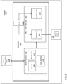
FIG. 1 is a block diagram illustrating an aircraft controller including a multi-core motor controller processor according to a non-limiting embodiment; -
FIG. 2 is a block diagram illustrating an electronic aircraft controller including a multi-core motor controller processor according to another non-limiting embodiment; and -
FIG. 3 is a block diagram of a multi-core processor included in an aircraft controller according to a non-limiting embodiment. - A detailed description of one or more embodiments of the disclosed apparatus and method are presented herein by way of exemplification and not limitation with reference to the Figures.
- The term "about" is intended to include the degree of error associated with measurement of the particular quantity based upon the equipment available at the time of filing the application.
- As used herein, the term "module" refers to an application specific integrated circuit (ASIC), an electronic circuit, a microprocessor, a computer processor (shared, dedicated, or group) and memory that executes one or more software or firmware programs, a combinational logic circuit, a microcontroller including various inputs and outputs, and/or other suitable components that provide the described functionality. The module is configured to execute various algorithms, transforms, and/or logical processes to generate one or more signals of controlling a component or system. When implemented in software, a module can be embodied in memory as a non-transitory machine-readable storage medium readable by a processing circuit (e.g., a microprocessor) and storing instructions for execution by the processing circuit for performing a method. A controller refers to an electronic hardware controller including a storage unit capable of storing algorithms, logic or computer executable instruction, and that contains the circuitry necessary to interpret and execute instructions.
- Turning now to a description of technologies that are more relevant to the present teachings, the single core processor of a conventional motor controller is capable of handling motor and power inverter controls. The motor controller single core processor, however, cannot sufficiently process additional data types such as, for example, prognostics and diagnostics data. Consequently, conventional motor systems are incapable of incorporating prognostics and diagnostics data analysis schemes to perform maintenance and health predictions to potentially mitigate or eliminate faults before they occur.
- Various non-limiting embodiments described herein provide a multi-core motor controller processor configured to perform prognostic/diagnostic data processing and analysis. The multi-core motor controller processor includes multiple cores capable of performing power management and delivery for motor control and power inversion, while also performing prognostic/diagnostic data processing and analysis to perform maintenance and health predictions to potentially mitigate or eliminate faults before they occur. The added prognostic/diagnostic core can be partitioned from the motor/inverter control core to avoid the need to employ a separate additional power supply, thereby avoiding introduction of failure points and power signal noise into the prognostic/diagnostic data signals. The partition also prevents any unintended interactions with the motor control software in the power/inverter core.
- In at least one embodiment, one or more of the added cores can be selectively deactivated when a design scheme does not require a dedicated core. Accordingly, a common core of included in the multi-core motor controller processor can still be used across multiple systems or platforms. The multi-core controller processor described herein can be sized the same as the previous single core processor (i.e., have the same size die) while requiring the same core voltage as the originally considered processor. Accordingly, the need for a separate processor and power supply can be avoided.
- With reference now to
FIG. 1 , anelectronic aircraft controller 100 installed on anaircraft 102 is illustrated according to a non-limiting embodiment. Theaircraft controller 100 includes amain processor 104 in signal communication with amulti-core processor 106. - The
main processor 104 is in signal communication with anaircraft communication system 108 to receive operational commands from the aircraft system. The operation commands include, but are not limited to, motor control commands, software download enable commands, power commands. Electrical operational information such as, for example voltages, current, speed/frequency, protection status from theelectrical system 121 can be returned to theaircraft system 102. - The
main processor 104 includes aprotection unit 110, amode unit 112, and acommunications unit 114. Any one of theprotection unit 110,mode unit 112, andcommunications unit 114 can be constructed as an electronic hardware controller that includes memory and a processor configured to execute algorithms and computer-readable program instructions stored in the memory. - The
protection unit 110 is configured to employ various protection measures. The protection measures aim to protect various systems of the aircraft including, but not limited motor system, power generation systems, power distribution system, and motor controller LRUs. Some examples would be over/under/unbalanced current protection, over/under voltage protection, over/under speed protection, over frequency protection, and over temperature protection. The protection operation can include, for example, disconnecting components or shutting down sub-systems when an over/under protection event is detected. - The
mode unit 112 is configured to invoke different modes of theelectrical system 121. In the example of a motor system, themode unit 112 can invoke different operating modes of one ormore motors 122. In some instances, different motors may operate according to different operational logic and protections. For example, themode controller 112 can invoke one mode to operate a permanent magnet motor, and invoke another mode to operate an induction motor. - The
communications unit 114 is configured to facilitate inter-processor communication on theaircraft 102. In at least one embodiment, thecommunications unit 114 can facilitate data exchange between theaircraft 102 and the multi-core processor. - The
multi-core motor processor 106 includes one ormore control cores 116, one ormore prognostics cores 118, and one or more sharedmemory units 120. Thecontrol core 116 is in signal communication with anelectrical system 121 to control power delivered thereto. Theelectrical system 121 includes, but is not limited to, a motor system including one ormore motors 122, a power generator system, and a power distribution system. Thecontrol core 116 and theprognostic core 118 can each be constructed as an independent processing unit referred to as "a core", which is capable of reading and executing program instructions. The program instructions include various central processing unit (CPU) instructions including, but not limited to, add instructions, data move instructions, and branch instructions. - The
control core 116 generates controls signals that control operation of a power inverter circuit (not shown), for example, which drives amotor 122. Although onemotor 122 is illustrated, thecontrol core 116 and/or power inverter circuit can drive several different motors. Thecontrol core 116 can performs the actual control of different motors based on current, voltage, or speed and receives run, stop, and/or protection commands from themain processor 104. In at least one embodiment, the control core(s) 116 and its operations can be assigned a higher priority level than the prognostic core(s) 118. - The
prognostics core 118 is configured to generate prognostics and diagnostics data of theelectrical system 121, e.g., themotor 122. In one or more embodiments, the electrical system operating data includes, for example, voltage data, current data, load data, torque data, temperature data, and frequency data. Data can be passed from themain processor 104 to theprognostics core 118. Data can also be passed from thecontrol core 116 to theprognostics core 118. Theprognostics core 118 is configured to process the obtained data into prognostics and diagnostics data, which has format that can be used by a health management system (not shown). - In one or more embodiments, each
prognostics core 118 is partitioned (i.e., in space and time) from the control core(s) 116. The partitioning refers to partitioning theprognostics core 118 in space and time from thecontrol core 116. In other words, theprognostics core 118 is partitioned in space such that no other partition can change this partition's memory or affect its allocated time to execute. Accordingly, a separate additional power supply in not required to power the prognostic core(s) 118 thereby avoiding introduction of failure points and power signal noise into the prognostic/diagnostic data signals. The partition also prevents any unintended interactions with the motor control software installed thecontrol core 116. Accordingly, theprognostic core 118 can operate while the aircraft is in-flight to obtain motor operational data and perform prognostic/diagnostic processing and analysis without seizing any cycles from the control core or interrupting the higher priority processing operations (e.g., motor control operations) of thecontrol core 116. For example, theprognostics core 118 will be prevented from operating themotor 122, while thecontrol core 116 can operate entirely independent of theprognostics core 118. In at least one embodiment, thecontrol core 116 is also capable of enabling/disabling theprognostics core 118, while theprognostics core 118 is prevented from interrupting thecontrol core 116 and/or themain processor operation 104. - The shared
memory unit 120 is in signal communication with both thecontrol core 116 and theprognostics core 118. In one or more embodiments, thecontrol core 116 is configured to obtain operating data during operation of themotor 122 and store the operating data in the sharedmemory unit 120. Theprognostics core 118 is configured to obtain the operating data from the sharedmemory unit 120, and process and analyze the operating data to perform maintenance and health predictions of themotor 122. In some embodiments, the sharedmemory unit 120 can be integrated with multi-core processor 106) (e.g., installed within the multi-core processor 106) as illustrated inFIG. 1 . In other embodiments, the sharedmemory unit 120 can be installed externally from themulti-core processor 106 as illustrated inFIG. 2 . In some embodiments, a plurality of sharedmemory units 120 can be employed when a plurality ofcontrol cores 116 are included in themulti-core processor 106. In this scenario, some sharedmemory units 120 can be integrated in somecontrol cores 116, while other sharedmemory units 120 are installed externally from both thecontrol core 116 and theprognostics core 118. - Turning to
FIG. 3 , theaircraft controller 100 is illustrated according to another non-limiting embodiment. Theaircraft controller 100 includes amulti-core processor 106 and a mainmulti-core processor 200. Themulti-core processor 106 is in signal communication with anelectrical system 121. Themulti-core processor 106 operates in a similar manner as described in detail herein, and therefore will not be repeated for the sake of brevity. In this example, theelectrical system 121 is constructed as a power distribution system or a power generator system, but is not limited thereto. - The main
multi-core processor 200 includes aprognostics core 202, a plurality ofcontrol cores memory unit 206. Although a total of fourcores multi-core processor 200 can have additional cores (e.g., 8 total cores) without departing from the scope of the invention. - The main
multi-core processor 200 can control operation of low-power components 210. These low-power components 210 include, but are not limited to, relays, contact switches, light indicators, lamps, etc. Thecontrol cores control core 204a can control operating modes of theelectrical system 121, whilecontrol cores 204b controls circuit protections. In at least one embodiment, each of thecontrol cores memory location respective core - The
prognostics core 202 can receive a configuration signal (not shown) indicating one or more of the designatedmemory location prognostics core 202 upon each startup of the system, and directs theprognostics core 202 to one or more of the designatedmemory location aircraft 102. - As described herein, various embodiments provide a multi-core processor that includes one or more control cores capable of high-priority power control such as, for example, power inversion and motor control, while a separately partitioned prognostics core performs lower-priority prognostic/diagnostic data processing and analysis. The partitioning of the prognostics core prevents any unintended interactions with the control core software, and also avoids cycle usage and interruption of the control core, thereby allowing the prognostics core to operate while the aircraft is operating in-flight.
- The terminology used herein is for the purpose of describing particular embodiments only and is not intended to be limiting of the present disclosure. As used herein, the singular forms "a", "an" and "the" are intended to include the plural forms as well, unless the context clearly indicates otherwise. It will be further understood that the terms "comprises" and/or "comprising," when used in this specification, specify the presence of stated features, integers, steps, operations, elements, and/or components, but do not preclude the presence or addition of one or more other features, integers, steps, operations, element components, and/or groups thereof.
- While the present disclosure has been described with reference to an exemplary embodiment or embodiments, it will be understood by those skilled in the art that various changes may be made and equivalents may be substituted for elements thereof without departing from the scope of the invention as defined by the claims. In addition, many modifications may be made to adapt a particular situation or material to the teachings of the present disclosure without departing from the scope of the invention. Therefore, it is intended that the present disclosure not be limited to the particular embodiment disclosed as the best mode contemplated for carrying out this present disclosure, but that the present disclosure will include all embodiments falling within the scope of the claims.
Claims (15)
- An aircraft comprising:an electrical system (121) installed on the aircraft;an electronic controller (100) in signal communication with the electrical system, the electronic controller including a main processor (104) and a multi-core processor (106), the multi-core processor including at least one control core (116) in signal communication with the electrical system to control power delivered thereto, and at least one prognostics core (118) configured to process and analyze prognostics and diagnostics data of the electrical system independently from operation of the control core.
- The aircraft of claim 1, wherein the at least one prognostics core is partitioned from the at least one control core and performs processing and analysis of the prognostics and diagnostics data without using processing cycles of the control core.
- The aircraft of claim 2, wherein the electronic controller further includes a shared memory unit (120) in signal communication with the at least one control core and the at least one prognostics core.
- The aircraft of claim 3, wherein the at least one control core is configured to store operating data obtained during operation of the electrical system in the shared memory unit, and the at least one prognostics core is configured to obtain the operating data from the shared memory unit, and process and analyze the operating data to perform maintenance and health predictions of the electrical system.
- The aircraft of claim 2, wherein the at least one prognostics core performs the processing and analysis of the prognostics and diagnostics data during in-flight operation of the aircraft.
- The aircraft of any preceding claim, wherein the electrical system is a motor system including at least one motor.
- The aircraft of any preceding claim, wherein the electrical system includes one or both of a power distribution system and a power generator system.
- An electronic aircraft controller configured to control an electrical system of an aircraft, the aircraft controller comprising:
a multicore processor (106) comprising:at least one control core (116) configured to generate a power control signal to control the electrical system; andat least one prognostics core (118) configured to process and analyze prognostics and diagnostics data of the electrical system independently from operation of the control core. - The aircraft controller of claim 8, wherein the at least one prognostics core is partitioned from the at least one control core and performs processing and analysis of the prognostics and diagnostics data without using processing cycles of the control core.
- The aircraft controller of claim 9, wherein the electronic controller further includes a shared memory unit in signal communication with the at least one control core and the at least one prognostics core.
- The aircraft controller of claim 10, wherein the at least one control core is configured to store operating data obtained during operation of the electrical system in the shared memory unit, and the at least one prognostics core is configured to obtain the operating data from the shared memory unit, and process and analyze the operating data to perform maintenance and health predictions of the electrical system.
- The aircraft controller of claim 9, wherein the at least one prognostics core performs the processing and analysis of the prognostics and diagnostics data during in-flight operation of the aircraft.
- The aircraft controller of claim 9, further comprising a main processor (200) in signal communication with the multi-core processor, the main processor configured to perform at least one of an aircraft flight protection operation, an aircraft mode control operation and a diagnostics communications operation based on the process and analyze prognostics and diagnostics data generated by the prognostics core.
- A method of controlling an electrical system installed in an aircraft, the method comprising:outputting, via at least one control core included in a multi-core processor, power signals to operate the electrical system;returning operating data from the electrical system to the at least one control core;processing, via a prognostics core included in the multi-core processor, the operating data independently from operation of the control core; andgenerating prognostics and diagnostics data of the electrical system based on the operating data independently from operation of the control core.
- The method of claim 14, further comprising partitioning the at least one prognostics core from the at least one control core, and processing the operating data without using processing cycles of the control core.
Applications Claiming Priority (1)
| Application Number | Priority Date | Filing Date | Title |
|---|---|---|---|
| US16/205,304 US11097857B2 (en) | 2018-11-30 | 2018-11-30 | Multiple core motor controller processor with embedded prognostic/diagnostic capabilities |
Publications (1)
| Publication Number | Publication Date |
|---|---|
| EP3660604A1 true EP3660604A1 (en) | 2020-06-03 |
Family
ID=68581288
Family Applications (1)
| Application Number | Title | Priority Date | Filing Date |
|---|---|---|---|
| EP19208650.2A Ceased EP3660604A1 (en) | 2018-11-30 | 2019-11-12 | Multiple core motor controller processor with embedded prognostic/diagnostic capabilities |
Country Status (2)
| Country | Link |
|---|---|
| US (1) | US11097857B2 (en) |
| EP (1) | EP3660604A1 (en) |
Cited By (1)
| Publication number | Priority date | Publication date | Assignee | Title |
|---|---|---|---|---|
| EP4250027A1 (en) * | 2022-03-24 | 2023-09-27 | Rolls-Royce Deutschland Ltd & Co KG | System and method for machine diagnosis |
Citations (3)
| Publication number | Priority date | Publication date | Assignee | Title |
|---|---|---|---|---|
| DE102014019531A1 (en) * | 2014-12-23 | 2016-06-23 | Liebherr-Aerospace Lindenberg Gmbh | Method for operating an aircraft control component and control component |
| US20170147008A1 (en) * | 2013-11-26 | 2017-05-25 | Airbus Operations (Sas) | Flight management system of an aircraft |
| EP3660605A1 (en) * | 2018-11-29 | 2020-06-03 | Hamilton Sundstrand Corporation | Aircraft controller including multiple core processor with wireless transmission prognostic/diagnostic data capability |
Family Cites Families (7)
| Publication number | Priority date | Publication date | Assignee | Title |
|---|---|---|---|---|
| US20080147571A1 (en) * | 2006-09-29 | 2008-06-19 | Caterpillar Inc. | System and method for analyzing machine customization costs |
| US9703595B2 (en) * | 2008-10-02 | 2017-07-11 | Mindspeed Technologies, Llc | Multi-core system with central transaction control |
| US20130046509A1 (en) * | 2011-08-19 | 2013-02-21 | Oracle International Corporation | Multi-core processor test system and method |
| US8838300B2 (en) * | 2012-04-12 | 2014-09-16 | The Boeing Company | Standby aircraft management system |
| US9481473B2 (en) * | 2013-03-15 | 2016-11-01 | Rolls-Royce North American Technologies, Inc. | Distributed control system with smart actuators and sensors |
| US9678488B1 (en) | 2013-11-19 | 2017-06-13 | The Boeing Company | System and method for vehicle build verification |
| US20170256957A1 (en) | 2016-03-04 | 2017-09-07 | G4 Synergetics, Inc. | Hybrid power delivery with improved power control |
-
2018
- 2018-11-30 US US16/205,304 patent/US11097857B2/en active Active
-
2019
- 2019-11-12 EP EP19208650.2A patent/EP3660604A1/en not_active Ceased
Patent Citations (3)
| Publication number | Priority date | Publication date | Assignee | Title |
|---|---|---|---|---|
| US20170147008A1 (en) * | 2013-11-26 | 2017-05-25 | Airbus Operations (Sas) | Flight management system of an aircraft |
| DE102014019531A1 (en) * | 2014-12-23 | 2016-06-23 | Liebherr-Aerospace Lindenberg Gmbh | Method for operating an aircraft control component and control component |
| EP3660605A1 (en) * | 2018-11-29 | 2020-06-03 | Hamilton Sundstrand Corporation | Aircraft controller including multiple core processor with wireless transmission prognostic/diagnostic data capability |
Non-Patent Citations (1)
| Title |
|---|
| PATRICK HUYCK: "ARINC 653 and multi-core microprocessors Considerations and potential impacts", DIGITAL AVIONICS SYSTEMS CONFERENCE (DASC), 2012 IEEE/AIAA 31ST, IEEE, 14 October 2012 (2012-10-14), pages 6B4 - 1, XP032279753, ISBN: 978-1-4673-1699-6, DOI: 10.1109/DASC.2012.6382387 * |
Cited By (2)
| Publication number | Priority date | Publication date | Assignee | Title |
|---|---|---|---|---|
| EP4250027A1 (en) * | 2022-03-24 | 2023-09-27 | Rolls-Royce Deutschland Ltd & Co KG | System and method for machine diagnosis |
| US12304650B2 (en) | 2022-03-24 | 2025-05-20 | Rolls-Royce Deutschland Ltd & Co Kg | System and method for machine diagnosis |
Also Published As
| Publication number | Publication date |
|---|---|
| US20200172268A1 (en) | 2020-06-04 |
| US11097857B2 (en) | 2021-08-24 |
Similar Documents
| Publication | Publication Date | Title |
|---|---|---|
| EP3660605B1 (en) | Aircraft controller including multiple core processor with wireless transmission prognostic/diagnostic data capability | |
| EP3076293A2 (en) | Control apparatus | |
| US9170832B2 (en) | Virtual machine control apparatus and virtual machine control method | |
| JP6054010B2 (en) | Data determination apparatus, data determination method, and program | |
| US10006455B2 (en) | Drive control apparatus | |
| EP3249534A1 (en) | Vehicle control device | |
| US10956238B2 (en) | Programmable controller, management device, and control system | |
| US10822107B1 (en) | Integration of vehicle management system and power distribution control | |
| US11334379B2 (en) | Control device | |
| US11097857B2 (en) | Multiple core motor controller processor with embedded prognostic/diagnostic capabilities | |
| US20220402121A1 (en) | Control and monitoring of a machine arrangement | |
| CN107342710B (en) | Apparatus for controlling a plurality of inverters and inverter system including the same | |
| US11358473B2 (en) | Vehicle management system and parallel power distribution lines | |
| CN119058390B (en) | Domain controller startup management circuit, method, MCU, domain controller and vehicle | |
| US11340561B2 (en) | Control system, support device, and storage medium | |
| US12093030B2 (en) | Control system, support device, and storage medium to allow determination whether specifications of safety functions are satisfied | |
| US20200331351A1 (en) | Vehicle management system and replacement of separate power distribution units | |
| US10353744B2 (en) | System wide manageability | |
| US12147827B2 (en) | Vehicle control device, vehicle control method, and recording medium recording control program | |
| JP6229637B2 (en) | In-vehicle control device | |
| US11283375B2 (en) | Slave unit and servo driving system | |
| US20210356925A1 (en) | Control system, control method, and drive device | |
| JP6268071B2 (en) | Electronic control unit | |
| CN119532220A (en) | Fan control method, device and server | |
| EP4328676A1 (en) | Digital output apparatus and method for generating digital output |
Legal Events
| Date | Code | Title | Description |
|---|---|---|---|
| PUAI | Public reference made under article 153(3) epc to a published international application that has entered the european phase |
Free format text: ORIGINAL CODE: 0009012 |
|
| STAA | Information on the status of an ep patent application or granted ep patent |
Free format text: STATUS: THE APPLICATION HAS BEEN PUBLISHED |
|
| AK | Designated contracting states |
Kind code of ref document: A1 Designated state(s): AL AT BE BG CH CY CZ DE DK EE ES FI FR GB GR HR HU IE IS IT LI LT LU LV MC MK MT NL NO PL PT RO RS SE SI SK SM TR |
|
| AX | Request for extension of the european patent |
Extension state: BA ME |
|
| STAA | Information on the status of an ep patent application or granted ep patent |
Free format text: STATUS: REQUEST FOR EXAMINATION WAS MADE |
|
| 17P | Request for examination filed |
Effective date: 20201203 |
|
| RBV | Designated contracting states (corrected) |
Designated state(s): AL AT BE BG CH CY CZ DE DK EE ES FI FR GB GR HR HU IE IS IT LI LT LU LV MC MK MT NL NO PL PT RO RS SE SI SK SM TR |
|
| STAA | Information on the status of an ep patent application or granted ep patent |
Free format text: STATUS: EXAMINATION IS IN PROGRESS |
|
| 17Q | First examination report despatched |
Effective date: 20220708 |
|
| APBK | Appeal reference recorded |
Free format text: ORIGINAL CODE: EPIDOSNREFNE |
|
| APBN | Date of receipt of notice of appeal recorded |
Free format text: ORIGINAL CODE: EPIDOSNNOA2E |
|
| APAF | Appeal reference modified |
Free format text: ORIGINAL CODE: EPIDOSCREFNE |
|
| APBT | Appeal procedure closed |
Free format text: ORIGINAL CODE: EPIDOSNNOA9E |
|
| STAA | Information on the status of an ep patent application or granted ep patent |
Free format text: STATUS: THE APPLICATION HAS BEEN REFUSED |
|
| 18R | Application refused |
Effective date: 20231227 |