EP3660596A1 - Fixing device and image forming apparatus incorporating same - Google Patents
Fixing device and image forming apparatus incorporating same Download PDFInfo
- Publication number
- EP3660596A1 EP3660596A1 EP19211866.9A EP19211866A EP3660596A1 EP 3660596 A1 EP3660596 A1 EP 3660596A1 EP 19211866 A EP19211866 A EP 19211866A EP 3660596 A1 EP3660596 A1 EP 3660596A1
- Authority
- EP
- European Patent Office
- Prior art keywords
- nip
- fixing belt
- fixing
- forming portion
- nip forming
- Prior art date
- Legal status (The legal status is an assumption and is not a legal conclusion. Google has not performed a legal analysis and makes no representation as to the accuracy of the status listed.)
- Granted
Links
Images




Classifications
-
- G—PHYSICS
- G03—PHOTOGRAPHY; CINEMATOGRAPHY; ANALOGOUS TECHNIQUES USING WAVES OTHER THAN OPTICAL WAVES; ELECTROGRAPHY; HOLOGRAPHY
- G03G—ELECTROGRAPHY; ELECTROPHOTOGRAPHY; MAGNETOGRAPHY
- G03G15/00—Apparatus for electrographic processes using a charge pattern
- G03G15/20—Apparatus for electrographic processes using a charge pattern for fixing, e.g. by using heat
- G03G15/2003—Apparatus for electrographic processes using a charge pattern for fixing, e.g. by using heat using heat
- G03G15/2014—Apparatus for electrographic processes using a charge pattern for fixing, e.g. by using heat using heat using contact heat
- G03G15/2017—Structural details of the fixing unit in general, e.g. cooling means, heat shielding means
- G03G15/2028—Structural details of the fixing unit in general, e.g. cooling means, heat shielding means with means for handling the copy material in the fixing nip, e.g. introduction guides, stripping means
-
- G—PHYSICS
- G03—PHOTOGRAPHY; CINEMATOGRAPHY; ANALOGOUS TECHNIQUES USING WAVES OTHER THAN OPTICAL WAVES; ELECTROGRAPHY; HOLOGRAPHY
- G03G—ELECTROGRAPHY; ELECTROPHOTOGRAPHY; MAGNETOGRAPHY
- G03G15/00—Apparatus for electrographic processes using a charge pattern
- G03G15/20—Apparatus for electrographic processes using a charge pattern for fixing, e.g. by using heat
- G03G15/2003—Apparatus for electrographic processes using a charge pattern for fixing, e.g. by using heat using heat
- G03G15/2014—Apparatus for electrographic processes using a charge pattern for fixing, e.g. by using heat using heat using contact heat
- G03G15/2053—Structural details of heat elements, e.g. structure of roller or belt, eddy current, induction heating
-
- G—PHYSICS
- G03—PHOTOGRAPHY; CINEMATOGRAPHY; ANALOGOUS TECHNIQUES USING WAVES OTHER THAN OPTICAL WAVES; ELECTROGRAPHY; HOLOGRAPHY
- G03G—ELECTROGRAPHY; ELECTROPHOTOGRAPHY; MAGNETOGRAPHY
- G03G2215/00—Apparatus for electrophotographic processes
- G03G2215/20—Details of the fixing device or porcess
- G03G2215/2003—Structural features of the fixing device
- G03G2215/2016—Heating belt
- G03G2215/2035—Heating belt the fixing nip having a stationary belt support member opposing a pressure member
Definitions
- Embodiments of the present disclosure generally relate to a fixing device and an image forming apparatus incorporating the fixing device.
- An image forming apparatus such as a copier, a printer, a facsimile machine, and a multi-functional apparatus including at least two functions of the copier, printer, facsimile machine includes a fixing device to convey a recording medium such as a sheet on which an unfixed image is formed to a fixing nip formed between a fixing belt and a pressing member in the fixing device, heat the recording medium, and fix the unfixed image onto the recording medium.
- a fixing device to convey a recording medium such as a sheet on which an unfixed image is formed to a fixing nip formed between a fixing belt and a pressing member in the fixing device, heat the recording medium, and fix the unfixed image onto the recording medium.
- the fixing device includes a nip formation pad that is disposed inside of a loop of the fixing belt and contacts the pressing member via the fixing belt to form the fixing nip, and a support to support the nip formation pad.
- the recording medium that has passed through the fixing nip needs to be separated from the fixing belt and conveyed downstream.
- a large separation angle is set as an angle between the fixing belt and the conveyance direction of the recording medium after the recording medium passes through the fixing nip.
- a nip plate 103 abuts a pressure roller 102 via a fixing belt 101 to form a fixing nip N.
- the nip plate 103 includes, e.g., a flat plate-shaped portion 103a, a bent portion 103b extending downward from the rear end of the plate-shaped portion 103a, and a bottom portion 103c extending rearward from a lower end of the bent portion 103b.
- the conveyance direction of the sheet S heated and pressed in the fixing nip N is changed by the bent portion 103b. That is, the separation angle ⁇ is formed between the conveyance direction of the sheet S and the fixing belt 101, and the sheet S is separated from the fixing belt 101.
- JP-2014-66851-A when the bent portion bent toward the pressure member is disposed downstream from the fixing nip, the separation angle of the recording medium from the fixing belt can be increased, thus enhancing the separability of the recording medium.
- the portion downstream from the bent portion 103b is not in contact with the pressure member. Accordingly, a nip portion is not formed between the pressure member and the downstream portion, which causes a problem in that the length of the fixing nip in the conveyance direction becomes small. Therefore, depending on the configuration of the fixing device, there is a problem that the recording medium cannot be heated sufficiently.
- an object of the present disclosure is to sufficiently heat the recording medium and to ensure the separability of the recording medium from the fixing belt after the fixing operation.
- a fixing device that includes a fixing belt, a pressure member, a nip formation member, a heater, and a support.
- the fixing belt has an endless shape.
- the pressure member is configured to press the fixing belt.
- the nip formation member is disposed inside a loop of the fixing belt and configured to contact the pressure member via the fixing belt.
- the heater is configured to heat the fixing belt.
- the support is disposed inside the loop of the fixing belt and configured to support the nip formation member.
- the nip formation member includes a first nip forming portion, a second nip forming portion, an inflection portion, and a supported portion.
- the first nip forming portion is configured to contact the pressure member via the fixing belt to form a first fixing nip.
- the second nip forming portion is disposed downstream from the first nip forming portion in a direction of conveyance of a recording medium and configured to contact the pressure member via the fixing belt to form a second fixing nip.
- a direction of extension of the nip formation member changes at the inflection portion.
- the supported portion is disposed downstream from the first nip forming portion in the direction of conveyance of the recording medium.
- the supported portion is supported by and in contact with the support.
- the inflection portion is disposed at a position of the supported portion or a position downstream from the supported portion in the direction of conveyance of the recording medium.
- the second nip forming portion is disposed downstream from the inflection portion.
- an image forming apparatus that includes the fixing device.
- the recording medium can be sufficiently heated while securing the separability of the recording medium from the fixing belt after the fixing operation.
- an image forming apparatus 1 includes an image forming device 2 disposed in a center portion of the image forming apparatus 1.
- the image forming device 2 includes four process units 9Y, 9M, 9C, and 9K (hereinafter, may be collectively referred to process unit(s) 9 unless distinguished) as removably installed in the image forming apparatus 1.
- the process units 9Y, 9M, 9C, and 9K contain developers (e.g., yellow, magenta, cyan, and black toners) in different colors, that is, yellow, magenta, cyan, and black corresponding to color separation components of a color image, respectively, the process units 9Y, 9M, 9C, and 9K have an identical structure.
- Each process unit 9 includes a photoconductor drum 10 serving as a rotatable image bearer to bear toner as the developer on the surface of the photoconductor drum 10, a charging roller 11 to uniformly charge the surface of the photoconductor drum 10, and a developing device 12 that includes a developing roller to supply toner to the surface of the photoconductor drum 10.
- an exposure device 3 is disposed below the process units 9Y, 9C, 9M, and 9K.
- the exposure device 3 emits laser light beams based on image data.
- the transfer device 4 includes, e.g., a drive roller 14, a driven roller 15, an intermediate transfer belt 16, and four primary transfer rollers 17.
- the intermediate transfer belt 16 is an endless belt rotatably stretched around the drive roller 14, the driven roller 15, and the like.
- Each of the four primary transfer rollers 17 is disposed opposite the corresponding photoconductor drum 10 in each of the process units 9Y, 9C, 9M, and 9K via the intermediate transfer belt 16.
- the primary transfer rollers 17 press against an inner circumferential surface of the intermediate transfer belt 16.
- primary transfer nips are formed at positions at which the photoconductor drums 10 contact respective pressed portions of the intermediate transfer belt 16 pressed by the primary transfer rollers 17.
- the drive roller 14 rotates the intermediate transfer belt 16.
- the transfer device 4 includes a secondary-transfer roller 18 disposed opposite the drive roller 14 via the intermediate transfer belt 16.
- the secondary-transfer roller 18 is pressed against an outer circumferential surface of the intermediate transfer belt 16, and thus a secondary-transfer nip is formed between the secondary-transfer roller 18 and the intermediate transfer belt 16.
- a sheet feeder 5 is disposed in a lower portion of the image forming apparatus 1.
- the sheet feeder 5 includes a sheet tray 19, which contains sheets P as recording media, and a sheet feeding roller 20 to feed the sheets P from the sheet tray 19.
- the sheets P are conveyed along a conveyance passage 6 from the sheet feeder 5 toward a sheet ejector 8.
- Conveyance roller pairs including a registration roller pair 21 are disposed along the conveyance passage 6.
- a fixing device 7 is disposed downstream from the secondary-transfer nip in a sheet conveyance direction.
- the fixing device 7 includes a fixing belt 22 heated by a heater and a pressure roller 23 as a pressing member to press the fixing belt 22.
- the sheet ejector 8 is disposed at an extreme downstream side of the conveyance passage 6 in the image forming apparatus 1.
- the sheet ejector 8 includes an ejection roller pair 24 and an output tray 25.
- the ejection roller pair 24 ejects the sheets P onto the output tray 25 disposed atop a housing of the image forming apparatus 1.
- the sheets P lie stacked on the output tray 25.
- removable toner bottles 29Y, 29C, 29M, and 29K are disposed.
- the toner bottles 29Y, 29C, 29M, and 29K are filled with fresh toner of yellow, cyan, magenta, and black, respectively.
- a toner supply tube is interposed between each of the toner bottles 29Y, 29C, 29M, and 29K and the corresponding developing device 12. The fresh toner is supplied from each of the toner bottles 29Y, 29C, 29M, and 29K to the corresponding developing device 12 through the toner supply tube.
- the exposure device 3 emits laser light beams onto the outer circumferential surfaces of the photoconductor drums 10 of the process units 9Y, 9M, 9C, and 9K according to image data, thus forming electrostatic latent images on the photoconductor drums 10.
- the image data used to expose the respective photoconductor drums 10 by the exposure device 3 is monochrome image data produced by decomposing a desired full color image into yellow, magenta, cyan, and black image data.
- the drum-shaped developing rollers of the developing devices 12 supply yellow, magenta, cyan, and black toners stored in the developing devices 12 to the electrostatic latent images, rendering visible the electrostatic latent images as developed visible images, that is, yellow, magenta, cyan, and black toner images, respectively.
- the intermediate transfer belt 16 moves along with rotation of the drive roller 14 in a direction indicated by arrow D in FIG. 1 .
- a power supply applies a constant voltage or a constant current control voltage having a polarity opposite a polarity of the toner to each primary transfer roller 17.
- a transfer electric field is formed at the primary transfer nip.
- the yellow, magenta, cyan, and black toner images are primarily transferred from the photoconductor drums 10 onto the intermediate transfer belt 16 successively at the primary transfer nips such that the yellow, magenta, cyan, and black toner images are superimposed on a same position on the intermediate transfer belt 16.
- the sheet feeding roller 20 of the sheet feeder 5 disposed in the lower portion of the image forming apparatus 1 is driven and rotated to feed a sheet P from the sheet tray 19 toward the registration roller pair 21 through the conveyance passage 6.
- the registration roller pair 21 conveys the sheet P fed to the conveyance passage 6 by the sheet feeding roller 20 to the secondary-transfer nip formed between the secondary-transfer roller 18 and the intermediate transfer belt 16 supported by the drive roller 14, timed to coincide with the superimposed toner image on the intermediate transfer belt 16.
- a transfer voltage having a polarity opposite the toner charge polarity of the toner image formed on the surface of the intermediate transfer belt 16 is applied to the sheet P and the transfer electric field is generated in the secondary-transfer nip. Due to the transfer electric field generated in the secondary transfer nip, the toner images formed on the intermediate transfer belt 16 are collectively transferred onto the sheet P.
- the sheet P bearing the full color toner image is conveyed to the fixing device 7 where the fixing belt 22 and the pressure roller 23 fix the full color toner image onto the sheet P under heat and pressure.
- the sheet P having the fixed toner image thereon is separated from the fixing belt 22 and conveyed by the conveyance roller pair to the sheet ejector 8.
- the ejection roller pair 24 of the sheet ejector 8 ejects the sheet P onto the output tray 25.
- the image forming apparatus 1 may form a monochrome toner image by using any one of the four process units 9Y, 9M, 9C, and 9K or may form a bicolor toner image or a tricolor toner image by using two or three of the process units 9Y, 9M, 9C, and 9K.
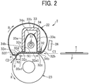
- the fixing device 7 includes the fixing belt 22, the pressure roller 23, a halogen heater 31 as a heater, a nip formation pad 32 as a nip formation member, a stay 33 as a support, and a reflector 34.
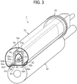
- the halogen heater 31, the nip formation pad 32, the stay 33, and the reflector 34 are disposed inside the loop of the fixing belt 22 and across the fixing belt 22 in a width direction of the fixing belt 22 that is a direction orthogonal to a sheet surface on which FIG. 2 is printed and hereinafter may be simply referred to as the width direction.
- the fixing belt 22 is a cylindrical fixing member to fix an unfixed image T to the sheet P and is disposed on the side of the sheet P on which the unfixed image T is held.
- the fixing belt 22 in the present embodiment is an endless belt or film, including a base layer formed on an inner side of the fixing belt 22 and made of a metal such as nickel and stainless steel (SUS) or a resin such as polyimide, and a release layer formed on the outer side of the fixing belt 22 and made of tetrafluoroethylene-perfluoroalkylvinylether copolymer (PFA), polytetrafluoroethylene (PTFE), or the like.
- SUS nickel and stainless steel
- PFA tetrafluoroethylene-perfluoroalkylvinylether copolymer
- PTFE polytetrafluoroethylene
- an elastic layer made of rubber such as silicone rubber, silicone rubber foam, and fluoro rubber may be interposed between the base layer and the release layer.
- the fixing belt 22 and the pressure roller 23 press the unfixed toner image against the sheet P to fix the toner image onto the sheet P
- the elastic layer having a thickness of about 100 micrometers elastically deforms to absorb slight surface asperities of the fixing belt 22, preventing variation in gloss of the toner image on the sheet P.
- the fixing belt 22 is thin and has a small loop diameter to decrease the thermal capacity of the fixing belt 22.
- the base layer of the fixing belt 22 has a thickness of from 20 ⁇ m to 50 ⁇ m and the release layer has a thickness of from 10 ⁇ m to 50 ⁇ m.
- the fixing belt 22 has a total thickness not greater than 1 mm.
- the thickness of the elastic layer may be set to 100 to 300 ⁇ m.
- the fixing belt 22 may have the total thickness not greater than 0.20 mm and preferably not greater than 0.16 mm.
- the fixing belt 22 may have a loop diameter from 20 to 40 mm and preferably 30 mm or less.
- the pressure roller 23 is an opposed member disposed opposite an outer circumferential surface of the fixing belt 22.
- the pressure roller 23 includes a cored bar; an elastic layer coating the cored bar and being made of silicone rubber foam, fluoro rubber, or the like; and a release layer coating the elastic layer and being made of PFA, PTFE, or the like.
- the pressure roller 23 is a solid roller.
- the pressure roller 23 may be a hollow roller.
- a heater such as a halogen heater may be disposed inside the pressure roller 23.
- the elastic layer of the pressure roller 23 may be made of solid rubber.
- the elastic layer of the pressure roller 23 is preferably made of sponge rubber to enhance thermal insulation of the pressure roller 23.
- Such a configuration reduces heat conduction from the fixing belt 22 to the pressure roller 23 and improves heating efficiency of the fixing belt 22.
- a driver disposed inside the image forming apparatus 1 drives and rotates the pressure roller 23 in the direction indicated by arrow A in FIG. 2 .
- the rotation of the pressure roller 23 drives the fixing belt 22 to rotate in a direction indicated by arrow B in FIG. 2 (hereinafter, belt rotation direction B) due to frictional force therebetween.
- belt rotation direction B belt rotation direction B
- the sheet P bearing the unfixed toner image T is sent to between the fixing belt 22 and the pressure roller 23.
- the rotating fixing belt 22 and the rotating pressure roller 23 convey the sheet P, and the sheet P passes through a fixing nip N1 and a fixing nip N2. Heat and pressure are applied to the sheet P to fix the unfixed toner image T onto the sheet P.
- the pressure roller 23 and the fixing belt 22 are configured to be able to contact and separate each other. If the sheet is jammed in the fixing nip N1 and the fixing nip N2, the pressure roller 23 and the fixing belt 22 are separated from each other and the fixing nip N1 and the fixing nip N2 are opened, thus allowing maintenance operation, such as removal of the jammed sheet.
- One of the pressure roller 23 and the fixing belt 22 may be configured to be fixed and the other may be configured to be movable so that the pressure roller 23 and the fixing belt 22 contact and separate each other.
- both the pressure roller 23 and the fixing belt 22 may be configured to move so that the pressure roller 23 and the fixing belt 22 contact and separate from each other.
- the halogen heater 31 is a heater disposed inside the loop of the fixing belt 22 to emit infrared light, and radiant heat from the halogen heater 31 heats the fixing belt 22 from the inside.
- a carbon heater, a ceramic heater or the like may be employed as the heater.
- one halogen heater 31 is disposed in the loop of the fixing belt 22, but a plurality of halogen heaters 31 having different heat generation areas may be used according to the width of the sheet.
- the nip formation pad 32 sandwiches the fixing belt 22 together with the pressure roller 23, to form the fixing nip N1 and the fixing nip N2.
- the nip formation pad 32 is disposed in the inner circumferential side of the fixing belt 22 to extend in a longitudinal shape in the width direction.
- the nip formation pad 32 includes, e.g., a first nip forming portion 32a, a bent portion 32b, and a second nip forming portion 32e.
- the first nip forming portion 32a has a flat shape and contacts the inner circumferential surface of the fixing belt 22.
- the bent portion 32b bends from an upstream end of the first nip forming portion 32a in the belt rotation direction B to the side opposite to the pressure roller 23.
- the second nip forming portion 32e which is described later, is disposed downstream from the first nip forming portion 32a in the belt rotation direction B.
- a pressing member such as a spring presses the pressure roller 23 against the nip formation pad 32, which causes the pressure roller 23 to contact the fixing belt 22 and form the fixing nip N1 and the fixing nip N2 between the pressure roller 23 and the fixing belt 22.
- the nip formation surface 32a1 of the first nip forming portion 32a and the nip formation surface 32e1 of the second nip forming portion 32e facing the fixing belt 22 are in direct contact with the inner circumferential surface of the fixing belt 22. As the fixing belt 22 rotates, the fixing belt 22 slides on the nip formation surfaces 32a1 and 32e1. To enhance the abrasion resistance and the slidability of the nip formation surface 32a1, preferably the nip formation surfaces 32a1 and 32e1 are treated with alumite or coated with a fluororesin material.
- a lubricant such as fluorine-based grease may be applied to the nip formation surfaces 32a1 and 32e1.
- the nip formation surface 32a1 is planar.
- the nip formation surface 32a1 may define recesses or other shapes.
- the nip formation pad 32 is made of a material having a thermal conductivity larger than a thermal conductivity of the stay 33.
- the material of the nip formation pad 32 is preferably copper (thermal conductivity: 398 W / mk) or aluminum (thermal conductivity: 236 W / mk).
- the nip formation pad 32 made of the material having such a large thermal conductivity absorbs the radiant heat from the halogen heater 31 and effectively transmits heat to the fixing belt 22.
- setting the thickness of the nip formation pad 32 to 1 mm or less can shorten a heat transfer time in which the heat transfers from the nip formation pad 32 to the fixing belt 22, which is advantageous in shortening a warm-up time of the fixing device 7.
- setting the thickness of the nip formation pad 32 to be larger than 1 mm and 5 mm or less can improve a heat storage capacity of the nip formation pad 32.
- the stay 33 is a support that indirectly contacts the nip formation pad 32 from the side (upper side in FIG. 2 ) opposite to the pressure roller 23 via another member (in the present embodiment, the bent portion 34b of the reflector 34) and supports the nip formation pad 32 against the pressure of the pressure roller 23. Similar to the nip formation pad 32, the stay 33 extends in a longitudinal shape in the width direction of the fixing belt 22 and is disposed inside the loop of the fixing belt 22. In the present embodiment, the stay 33 has a U-shaped cross-section including a pair of side wall portions 33a and a bottom wall portion 33b that connects the pair of side wall portions 33a.
- the pair of side wall portions 33a of the stay 33 supports both ends of the nip formation pad 32 in the belt rotation direction B.
- the side wall portions 33a extending in a direction in which the pressure roller 23 presses against the nip formation pad 32 that is a vertical direction in FIG. 2 strengthens the rigidity of the stay 33 in the direction in which the pressure roller 23 presses against the nip formation pad 32 and reduces the bend of the first nip forming portion 32a caused by the pressure force of the pressure roller 23.
- Such a configuration results in a uniform width of the nip in the longitudinal direction.
- the stay 33 is preferably made of an iron-based metal such as stainless steel (SUS) or Steel Electrolytic Cold Commercial (SECC) that is electrogalvanized sheet steel to ensure rigidity.
- the stay 33 "supports" the nip formation pad 32 means that a portion (in the present embodiment, the side wall portion 33a) of the stay 33 extending in the pressing direction of the pressure roller 23 (the vertical direction in FIG. 2 ) or a portion having a certain thickness is brought into contact with the nip formation pad 32 from the side (upper side in FIG. 2 ) opposite to the pressure roller 23.
- Such a configuration reduces the bend (in particular, the bend in the longitudinal direction in the present embodiment) of the nip formation pad 32 caused by the pressure from the pressure roller 23.
- the above-described contact includes not only the case where the stay 33 is in direct contact with the nip formation pad 32 but also the case where the stay 33 contacts the nip formation pad 32 via another member as in the present embodiment.
- the "contact via another member” means a state in which another member is interposed between the stay 33 and the nip formation pad 32 in the vertical direction in FIG.2 and at a position corresponding to at least a part of the member, the stay 33 contacts the member and the member contacts the nip formation pad 32.
- the term "extending in the pressing direction” is not limited to a case where the portion of the stay 33 extends in the same direction as the pressing direction of the pressure roller 23, but includes the case where the portion of the stay 33 extends in a direction with a certain angle from the pressing direction of the pressure roller 23. Even in such cases, the stay 33 can reduce the bend of the nip formation pad 32 against the pressing force from the pressure roller 23.
- the reflector 34 is disposed opposite the halogen heater 31 inside the loop of the fixing belt 22 to reflect the radiant heat that is infrared light emitted from the halogen heater 31 to the nip formation pad 32.
- the reflector 34 includes a reflector portion 34a formed as an ellipse cross-section and a pair of bent portions 34b bent from both ends of the reflector portion 34a in a direction in which the bent portions separate from each other in the belt rotation direction B.
- Each bent portion 34b is sandwiched between each side wall portion 33a of the stay 33 and the first nip forming portion 32a of the nip formation pad 32 to hold the reflector 34.
- An opening of an ellipse concave surface of the reflector portion 34a that opens toward the nip formation pad 32 reflects the radiant heat from the halogen heater 31 toward the nip formation pad 32. That is, the halogen heater 31 directly irradiates the nip formation pad 32 with the infrared light, and, additionally, the nip formation pad 32 is also irradiated with the infrared light reflected by the reflector portion 34a. Therefore, the nip formation pad 32 is effectively heated.
- the reflector portion 34a Since the reflector portion 34a is interposed between the halogen heater 31 and the stay 33, the reflector portion 34a functions to block the infrared light from the halogen heater 31 to the stay 33. The function reduces wasteful energy use to heat the stay 33. Additionally, in the present embodiment, the thermal insulation of the layer of air in a gap between the stay 33 and the reflector portion 34a further reduces heat transfer to the stay 33.
- the reflector 34 is provided to cover the halogen heater 31, and the radiant heat from the halogen heater 31 and the radiant heat reflected by the reflector 34 are efficiently collected to an opening of the reflector 34, that is, to the nip formation pad 32.
- the heated nip formation pad 32 can efficiently heat the fixing belt 22 in the fixing nips N1 and N2.
- the stay 33 covers the outer circumferential side of the reflector 34 and the fixing belt 22 is disposed outside the stay 33.
- the fixing belt 22 faces the halogen heater 31 via the nip formation pad 32 in the fixing nip N1 and, in the portion other than the fixing nip N1, faces the halogen heater 31 via the reflector 34 and the stay 33.
- the surface of the reflector portion 34a of the reflector 34 facing the halogen heater 31 is treated with mirror finish or the like to increase reflectance.
- reflectance is measured using the spectrophotometer that is the ultraviolet visible infrared spectrophotometer UH4150 manufactured by Hitachi High-Technologies Corporation in which the incident angle is set to be 5°.
- the color temperature of the halogen heater varies depending on the application.
- the color temperature of the heater for the fixing device is about 2500 K.
- the reflectance of the reflector 34 used in the present embodiment is preferably 70% or more with wavelengths of high emission intensity in the halogen heater 31, that is, specifically the wavelengths of 900 to 1600 nm and more preferably 70% or more with the wavelengths of 1000 to 1300 nm.
- the stay 33 may have the function of reflection and thermal insulation of the reflector 34.
- performing the thermal insulation treatment or the mirror finishing on the inner surface of the stay 33 in the halogen heater 31 side enables the stay 33 to function as the reflector 34.
- Such a configuration can obviate the reflector 34 that is a separate component from the stay 33.
- the reflectance of the stay 33 subjected to the mirror finishing is preferably similar to the reflectance of the reflector 34.
- the temperature sensors 28 are disposed outside the loop of the fixing belt 22 and detect temperatures of the fixing belt 22.
- the temperature sensors 28 are disposed at two positions, the central position in the width direction of the fixing belt 22, and one end position in the belt width direction of the fixing belt 22.
- Output of the halogen heater 31 is controlled based on the temperature of the outer circumferential surface of the fixing belt 22 detected by the temperature sensor 28.
- the temperature sensor 28 may be either contact type or non-contact type.
- the temperature sensor 28 may be a known temperature sensor type such as a thermopile, a thermostat, a thermistor, or a non-contact (NC) sensor.
- a pair of belt holders 35 is inserted in both lateral ends of the fixing belt 22 in the axial direction of the fixing belt 22 to rotatably support the fixing belt 22.
- the belt holders 35 inserted into the inner periphery of the fixing belt 22 support the fixing belt 22 in a state in which the fixing belt 22 is not basically applied with tension in a circumferential direction thereof while the fixing belt 22 does not rotate, that is, by a free belt system.
- the pressure roller 23 is biased toward the fixing belt 22 by a biasing member such as a spring at both ends in the longitudinal direction (see arrows H in FIG. 4 ) and pressed against the fixing belt 22. As a result, the elastic layer of the pressure roller 23 is pressed and deforms, and the fixing nip N is formed.
- a biasing member such as a spring at both ends in the longitudinal direction (see arrows H in FIG. 4 ) and pressed against the fixing belt 22.
- the second nip forming portion 32e provided in the nip formation pad 32 is further described with reference to FIG. 2 .
- the nip formation pad 32 includes the first nip forming portion 32a on an upstream side (right side in FIG. 2 ) in the sheet conveyance direction B and the second nip forming portion 32e on a downstream side from the first nip forming portion 32a.
- the first nip forming portion 32a has a substantially flat plate shape and is disposed in parallel with a direction C1 in which the sheet P enters the fixing nip N1.
- the second nip forming portion 32e is curved toward the pressure roller 23 from an inflection portion 32d that is a boundary between the first nip forming portion 32a and the second nip forming portion 32e.
- the second nip forming portion 32e is disposed closer to the pressure roller 23 than the first nip forming portion 32a in a direction (vertical direction in FIG. 2 ) of contact of the fixing belt 22 and the pressure roller 23.
- the second nip forming portion 32e is more inclined toward the pressure roller 23 (the lower side in FIG.
- the upstream side and the downstream side in the sheet conveyance direction may also be simply referred to as the upstream side and the downstream side.
- a supported portion 32c supported by the side wall portion 33a on the downstream side of the stay 33 is disposed at a downstream portion of the first nip forming portion 32a.
- a supported portion 32z supported by the side wall portion 33a on the upstream side of the stay 33 is also disposed at an upstream portion of the first nip forming portion 32a.
- a bent portion 32f is disposed that is bent from the downstream end of the second nip forming portion 32e to the side opposite to the pressure roller 23.
- the downstream side of the second nip forming portion 32e including the bent portion 32f is a free end that is not secured (supported) by the stay 33 or the like.
- the sheet P conveyed to the fixing device 7 is first conveyed in the direction indicated by arrow C1 and passes through the first fixing nip N1. That is, the sheet P is conveyed in the direction indicated by arrow C1 along the first nip forming portion 32a.
- the conveyance direction of the sheet P having passed through the first fixing nip N1 changes at the inflection portion 32d, and the sheet P is conveyed to the second fixing nip N2. That is, the sheet P is conveyed in the direction along the second nip forming portion 32e from the inflection portion 32d, and the conveyance direction of the sheet P changes in a direction indicated by arrow C2 that is a direction closer to the pressure roller 23.
- the sheet P is further conveyed and separated from the fixing belt 22 at a separation point D disposed at the downstream end of the second nip forming portion 32e.
- the sheet P is separates from the fixing belt 22 at a separation angle ⁇ formed by the fixing belt 22 and arrow C2 that is the conveyance direction of the sheet P toward the downstream side.
- the nip formation pad 32 includes the second nip forming portion 32e that is curved toward the pressure roller 23, thus allowing setting of the large separation angle ⁇ .
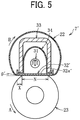
- a nip formation pad 32' of a fixing device 7' includes a nip forming portion 32a' having a substantially flat surface as illustrated in FIG. 5 , there is almost no difference between the sheet conveyance direction and the direction in which the fixing belt 22 extends downstream, which results in a small separation angle ⁇ '.
- the second nip forming portion 32e curved toward the pressure roller 23 is disposed on the downstream side of the nip formation pad 32 (in particular, the downstream end of the second nip forming portion 32e is disposed closer to the pressure roller 23 than the first nip forming portion 32a.
- the fixing belt 22 is greatly displaced to a lower side of FIG. 2 , at which the pressure roller 23 is disposed, on the downstream side in the sheet conveyance direction to contact the surface of the pressure roller 23.
- the pressure roller 23 is pressed against the fixing belt 22 to form a substantially horizontal fixing nip with the fixing belt 22 (in the range of the fixing nip N in FIG. 5 ).
- the fixing belt 22 is displaced toward the pressure roller 23 to contact the pressure roller 23, thus forming the second fixing nip N2.
- the second nip forming portion 32e deforms the fixing belt 22 toward the pressure roller 23.
- the fixing belt 22 can be raised in the conveyance direction C2 of the sheet P or in a direction away from the surface of the pressure roller 23. That is, the separation angle ⁇ of the sheet P can be set to be large, thus enhancing the separability of the sheet P from the fixing belt 22.
- the bent portion 32f bent to the opposite side of the pressure roller 23 is disposed at the downstream end of the second nip forming portion 32e.
- the direction in which the fixing belt 22 extends on the downstream side from the separation point D can be set to a direction along the bent portion 32f, thus allowing the separation angle ⁇ to be disposed at a stable angle.
- the separation point D can be disposed upstream from the downstream end of the nip formation pad 32, and the portion downstream from the separation point D, that is, the bent portion 32f in the present embodiment can also be provided as a guide portion to guide rotation of the fixing belt 22.
- the bent portion 32f may not be provided, and for example, the separation point D may be provided at the downstream end of the nip formation pad 32.
- the second nip forming portion 32e is curved toward the pressure roller 23. At a portion downstream from the supported portion 32c supported by the stay 33, the second nip forming portion 32e can also contact the pressure roller 23 to form the second fixing nip N2. Accordingly, the fixing nip having a sufficient length in the conveyance direction can be formed, thus enhancing the fixability of an image on the sheet surface.
- the inflection portion 32d between the first nip forming portion 32a and the second nip forming portion 32e is disposed at a position of the supported portion 32c at which the nip formation pad 32 is secured and supported by the stay 33.
- Such a configuration allows the size, shape, separation angle, and the like of the fixing nip in the conveyance direction to be changed at the inflection portion 32d acting as a boundary.
- the upstream end portion of the second nip forming portion 32e is supported by the stay 33 at the downstream end portion of the first nip forming portion 32a in the sheet conveyance direction.
- the upstream end portion of the second nip forming portion 32e is a fixed end fixed and supported by the stay 33.
- the downstream side of the second nip forming portion 32e including the bent portion 32f is a free end not fixed by the stay 33 or the like.
- the second nip forming portion 32e is formed of a material rich in elasticity and can be elastically deformed with the supported portion 32c as a fulcrum. It is desirable to provide the second nip forming portion 32e thinner than other portion of the nip formation pad 32 so that the second nip forming portion 32e can be easily elastically deformed.
- the pressure roller 23 is pressed in the direction indicated by arrow E by a pressing member such as a spring.
- a pressing member such as a spring.
- the pressure roller 23 is pressed against the fixing belt 22 to form the fixing nips N1 and N2.
- the pressing force of the pressure roller 23 to the fixing belt 22 can be changed to elastically deform and change the posture of the second nip forming portion 32e, thus changing the shape of the fixing nip N2.
- the pressing force is applied to the nip formation pad 32 via the fixing belt 22.
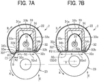
- the second nip forming portion 32e is elastically deformed to the side opposite to the pressure roller 23 with the supported portion 32c, which is the fixed end, acting as a fulcrum. Accordingly, as illustrated in FIG.
- the first nip forming portion 32a and the second nip forming portion 32e are arranged in a substantially straight line (substantially the same plane) and extend in a horizontal direction in the conveyance direction, to form one fixing nip N.
- the separation angle ⁇ 2 is smaller than the separation angle ⁇ 1 in FIG. 7A . Since the first nip forming portion 32a is fixed and supported at both ends by the stay 33, the shape of the first nip forming portion 32a hardly changes even if the pressing force is changed as described above.
- the arrangement of the pressure roller 23 or the arrangements of the fixing belt 22 and members in the fixing belt 22 may be changed to approach the pressure roller 23 and the fixing belt 22 each other or approach, to the pressure roller 23, a pressing means such as a spring that presses the pressure roller 23 in a direction to approach the fixing belt to increase the pressing force.
- the pressing means that presses the pressure roller 23 may be configured to vary the pressing force.
- the pressure roller 23 is pressed toward the fixing belt 22.
- the fixing belt 22 may be pressed toward the pressure roller 23.
- the fixing device 7 may include a biasing spring (biasing member or means) 37 to bias the second nip forming portion 32e toward the fixing belt 22 (lower side in FIG. 8 ).
- the posture of the second nip forming portion 32e may be changed by changing the posture of the biasing spring 37 (changing the biasing force of the spring).
- the biasing spring 37 is connected to a portion at the vicinity of the downstream end of the second nip forming portion 32e, to bias the connected portion toward the fixing belt 22. Changing the biasing force of the biasing spring 37 allows changing of the size, shape, the separation angle, and the like of the fixing nip in the conveyance direction.
- adjusting the pressing force of the pressure roller 23 to the fixing belt 22 allows changing of the size, shape, separation angle, and the like of the fixing nip in the conveyance direction. Accordingly, when the sheet P is unlikely to separate from the fixing belt 22, the posture of the second nip forming portion 32e is changed to have a large separation angle as illustrated in FIG. 7A . To reduce wrinkles of the sheet P, the posture of the second nip forming portion 32e is changed to form the fixing nip N in a substantially flat shape as illustrated in FIG. 7B . As described above, changing the posture of the second nip forming portion 32e according to the purpose allows changing of the fixing nip(s).
- the above-described adjustment of the separation angle or the like by changing the pressing force of the pressure roller 23 may be performed depending on, for example, the type or size of the sheet P that is passed through the fixing device 7. That is, the pressing force of the pressure roller 23 can be set in consideration of the ease of separation of the sheet P, the ease of occurrence of wrinkles, the image fixability, and the like based on the type and size of the sheet P.
- the second nip forming portion 32e being elastically deformable can be elastically deformed in the pressing direction (upward direction in FIG. 7A ) of the pressure roller 23, with the position of the inflection portion 32d as a start position.
- Such a configuration facilitates adjustment of the posture of the second nip forming portion 32e, that is, the separation angle and the shape of the fixing nip, thus facilitating the separation angle and the shape of the fixing nip to be changed to the target separation angle and the target shape of the fixing nip .
- the supported portion 32c may be provided at the inflection portion 32d between the first nip forming portion 32a and the second nip forming portion 32e, or at some midpoint in the first nip forming portion 32a upstream from the inflection portion 32d (see Fig. 2 )
- the image forming apparatus is not limited to a color image forming apparatus 1 illustrated in FIG. 1 but may be a monochrome image forming apparatus, a copier, a printer, a facsimile machine, or a multifunction peripheral including at least two functions of the copier, printer, and facsimile machine.
- the sheets P serving as recording media may be thick paper, postcards, envelopes, plain paper, thin paper, coated paper, art paper, tracing paper, overhead projector (OHP) transparencies, plastic film, prepreg, copper foil, and the like.
- OHP overhead projector
Landscapes
- Physics & Mathematics (AREA)
- General Physics & Mathematics (AREA)
- Fixing For Electrophotography (AREA)
Abstract
Description
- Embodiments of the present disclosure generally relate to a fixing device and an image forming apparatus incorporating the fixing device.
- An image forming apparatus such as a copier, a printer, a facsimile machine, and a multi-functional apparatus including at least two functions of the copier, printer, facsimile machine includes a fixing device to convey a recording medium such as a sheet on which an unfixed image is formed to a fixing nip formed between a fixing belt and a pressing member in the fixing device, heat the recording medium, and fix the unfixed image onto the recording medium.
- The fixing device includes a nip formation pad that is disposed inside of a loop of the fixing belt and contacts the pressing member via the fixing belt to form the fixing nip, and a support to support the nip formation pad.
- In such a type of fixing device, the recording medium that has passed through the fixing nip needs to be separated from the fixing belt and conveyed downstream. To enhance the separability of the recording medium from the fixing belt, a large separation angle is set as an angle between the fixing belt and the conveyance direction of the recording medium after the recording medium passes through the fixing nip.
- For example, in a
fixing device 100 as illustrated inJP-2014-66851-A FIG. 9 , anip plate 103 abuts apressure roller 102 via afixing belt 101 to form a fixing nip N. Thenip plate 103 includes, e.g., a flat plate-shaped portion 103a, abent portion 103b extending downward from the rear end of the plate-shaped portion 103a, and abottom portion 103c extending rearward from a lower end of thebent portion 103b. The conveyance direction of the sheet S heated and pressed in the fixing nip N is changed by thebent portion 103b. That is, the separation angle α is formed between the conveyance direction of the sheet S and thefixing belt 101, and the sheet S is separated from thefixing belt 101. - As in
JP-2014-66851-A JP-2014-66851-A bent portion 103b is not in contact with the pressure member. Accordingly, a nip portion is not formed between the pressure member and the downstream portion, which causes a problem in that the length of the fixing nip in the conveyance direction becomes small. Therefore, depending on the configuration of the fixing device, there is a problem that the recording medium cannot be heated sufficiently. - Under such circumstances, an object of the present disclosure is to sufficiently heat the recording medium and to ensure the separability of the recording medium from the fixing belt after the fixing operation.
- In an aspect of the present disclosure, there is provided a fixing device that includes a fixing belt, a pressure member, a nip formation member, a heater, and a support. The fixing belt has an endless shape. The pressure member is configured to press the fixing belt. The nip formation member is disposed inside a loop of the fixing belt and configured to contact the pressure member via the fixing belt. The heater is configured to heat the fixing belt. The support is disposed inside the loop of the fixing belt and configured to support the nip formation member. The nip formation member includes a first nip forming portion, a second nip forming portion, an inflection portion, and a supported portion. The first nip forming portion is configured to contact the pressure member via the fixing belt to form a first fixing nip. The second nip forming portion is disposed downstream from the first nip forming portion in a direction of conveyance of a recording medium and configured to contact the pressure member via the fixing belt to form a second fixing nip. A direction of extension of the nip formation member changes at the inflection portion. The supported portion is disposed downstream from the first nip forming portion in the direction of conveyance of the recording medium. The supported portion is supported by and in contact with the support. The inflection portion is disposed at a position of the supported portion or a position downstream from the supported portion in the direction of conveyance of the recording medium. The second nip forming portion is disposed downstream from the inflection portion.
- In another aspect of the present disclosure, there is provided an image forming apparatus that includes the fixing device.
- According to the present disclosure, the recording medium can be sufficiently heated while securing the separability of the recording medium from the fixing belt after the fixing operation.
- The aforementioned and other aspects, features, and advantages of the present disclosure would be better understood by reference to the following detailed description when considered in connection with the accompanying drawings, wherein:
-
FIG. 1 is a schematic sectional view of an image forming apparatus according to an embodiment of the present disclosure; -
FIG. 2 is a cross-sectional side view of a fixing device according to an embodiment of the present disclosure; -
FIG. 3 is a perspective view of the fixing device ofFIG. 2 ; -
FIG. 4 is a cross-sectional front view of the fixing device ofFIG. 2 ; -
FIG. 5 is a vertical cross-sectional view of a fixing device according to a comparative example; -
FIG. 6 is a vertical cross-sectional view of a fixing device according to another embodiment of the present disclosure; -
FIGS. 7A and 7B are cross-sectional side views of a fixing device according to still another embodiment of the present disclosure in a state of elastic deformation of a second nip forming portion; -
FIG. 8 is a side view of a biasing member that biases the second nip forming portion; and -
FIG. 9 is a cross-sectional side view of a conventional fixing device. - The accompanying drawings are intended to depict embodiments of the present disclosure and should not be interpreted to limit the scope thereof. The accompanying drawings are not to be considered as drawn to scale unless explicitly noted.
- In describing embodiments illustrated in the drawings, specific terminology is employed for the sake of clarity. However, the disclosure of this patent specification is not intended to be limited to the specific terminology so selected and it is to be understood that each specific element includes all technical equivalents that operate in a similar manner and achieve similar results.
- Although the embodiments are described with technical limitations with reference to the attached drawings, such description is not intended to limit the scope of the disclosure and all of the components or elements described in the embodiments of this disclosure are not necessarily indispensable.
- Referring now to the drawings, embodiments of the present disclosure are described below. Identical reference numerals are assigned to identical components or equivalents and a description of those components is simplified or omitted.
- As illustrated in
FIG. 1 , animage forming apparatus 1 according to an embodiment of the present disclosure includes animage forming device 2 disposed in a center portion of theimage forming apparatus 1. Theimage forming device 2 includes fourprocess units image forming apparatus 1. Although theprocess units process units - Each process unit 9 includes a
photoconductor drum 10 serving as a rotatable image bearer to bear toner as the developer on the surface of thephotoconductor drum 10, acharging roller 11 to uniformly charge the surface of thephotoconductor drum 10, and a developingdevice 12 that includes a developing roller to supply toner to the surface of thephotoconductor drum 10. - Below the
process units exposure device 3 is disposed. Theexposure device 3 emits laser light beams based on image data. - Above the
image forming device 2, atransfer device 4 is disposed. Thetransfer device 4 includes, e.g., adrive roller 14, a drivenroller 15, anintermediate transfer belt 16, and fourprimary transfer rollers 17. Theintermediate transfer belt 16 is an endless belt rotatably stretched around thedrive roller 14, the drivenroller 15, and the like. Each of the fourprimary transfer rollers 17 is disposed opposite thecorresponding photoconductor drum 10 in each of theprocess units intermediate transfer belt 16. At the different positions, theprimary transfer rollers 17 press against an inner circumferential surface of theintermediate transfer belt 16. Thus, primary transfer nips are formed at positions at which thephotoconductor drums 10 contact respective pressed portions of theintermediate transfer belt 16 pressed by theprimary transfer rollers 17. - The
drive roller 14 rotates theintermediate transfer belt 16. In addition, thetransfer device 4 includes a secondary-transfer roller 18 disposed opposite thedrive roller 14 via theintermediate transfer belt 16. The secondary-transfer roller 18 is pressed against an outer circumferential surface of theintermediate transfer belt 16, and thus a secondary-transfer nip is formed between the secondary-transfer roller 18 and theintermediate transfer belt 16. - A sheet feeder 5 is disposed in a lower portion of the
image forming apparatus 1. The sheet feeder 5 includes asheet tray 19, which contains sheets P as recording media, and asheet feeding roller 20 to feed the sheets P from thesheet tray 19. - The sheets P are conveyed along a conveyance passage 6 from the sheet feeder 5 toward a
sheet ejector 8. Conveyance roller pairs including aregistration roller pair 21 are disposed along the conveyance passage 6. - A fixing
device 7 is disposed downstream from the secondary-transfer nip in a sheet conveyance direction. The fixingdevice 7 includes a fixingbelt 22 heated by a heater and apressure roller 23 as a pressing member to press the fixingbelt 22. - The
sheet ejector 8 is disposed at an extreme downstream side of the conveyance passage 6 in theimage forming apparatus 1. Thesheet ejector 8 includes anejection roller pair 24 and anoutput tray 25. Theejection roller pair 24 ejects the sheets P onto theoutput tray 25 disposed atop a housing of theimage forming apparatus 1. Thus, the sheets P lie stacked on theoutput tray 25. - In an upper portion of the
image forming apparatus 1,removable toner bottles toner bottles toner bottles device 12. The fresh toner is supplied from each of thetoner bottles device 12 through the toner supply tube. - Next, a description is given of a basic operation of the
image forming apparatus 1 with reference toFIG. 1 . - As the
image forming apparatus 1 receives a print job and starts an image forming operation, theexposure device 3 emits laser light beams onto the outer circumferential surfaces of the photoconductor drums 10 of theprocess units exposure device 3 is monochrome image data produced by decomposing a desired full color image into yellow, magenta, cyan, and black image data. After theexposure device 3 forms the electrostatic latent images on the photoconductor drums 10, the drum-shaped developing rollers of the developingdevices 12 supply yellow, magenta, cyan, and black toners stored in the developingdevices 12 to the electrostatic latent images, rendering visible the electrostatic latent images as developed visible images, that is, yellow, magenta, cyan, and black toner images, respectively. - In the
transfer device 4, theintermediate transfer belt 16 moves along with rotation of thedrive roller 14 in a direction indicated by arrow D inFIG. 1 . A power supply applies a constant voltage or a constant current control voltage having a polarity opposite a polarity of the toner to eachprimary transfer roller 17. As a result, a transfer electric field is formed at the primary transfer nip. The yellow, magenta, cyan, and black toner images are primarily transferred from the photoconductor drums 10 onto theintermediate transfer belt 16 successively at the primary transfer nips such that the yellow, magenta, cyan, and black toner images are superimposed on a same position on theintermediate transfer belt 16. - As the image forming operation starts, the
sheet feeding roller 20 of the sheet feeder 5 disposed in the lower portion of theimage forming apparatus 1 is driven and rotated to feed a sheet P from thesheet tray 19 toward theregistration roller pair 21 through the conveyance passage 6. Theregistration roller pair 21 conveys the sheet P fed to the conveyance passage 6 by thesheet feeding roller 20 to the secondary-transfer nip formed between the secondary-transfer roller 18 and theintermediate transfer belt 16 supported by thedrive roller 14, timed to coincide with the superimposed toner image on theintermediate transfer belt 16. At this time, a transfer voltage having a polarity opposite the toner charge polarity of the toner image formed on the surface of theintermediate transfer belt 16 is applied to the sheet P and the transfer electric field is generated in the secondary-transfer nip. Due to the transfer electric field generated in the secondary transfer nip, the toner images formed on theintermediate transfer belt 16 are collectively transferred onto the sheet P. - The sheet P bearing the full color toner image is conveyed to the
fixing device 7 where the fixingbelt 22 and thepressure roller 23 fix the full color toner image onto the sheet P under heat and pressure. The sheet P having the fixed toner image thereon is separated from the fixingbelt 22 and conveyed by the conveyance roller pair to thesheet ejector 8. Theejection roller pair 24 of thesheet ejector 8 ejects the sheet P onto theoutput tray 25. - The above describes the image forming operation of the
image forming apparatus 1 to form the full color toner image on the sheet P. Alternatively, theimage forming apparatus 1 may form a monochrome toner image by using any one of the fourprocess units process units - As illustrated in
FIG. 2 , the fixingdevice 7 includes the fixingbelt 22, thepressure roller 23, ahalogen heater 31 as a heater, anip formation pad 32 as a nip formation member, astay 33 as a support, and areflector 34. As illustrated inFIG. 3 , thehalogen heater 31, thenip formation pad 32, thestay 33, and thereflector 34 are disposed inside the loop of the fixingbelt 22 and across the fixingbelt 22 in a width direction of the fixingbelt 22 that is a direction orthogonal to a sheet surface on whichFIG. 2 is printed and hereinafter may be simply referred to as the width direction. - As illustrated in
FIG. 2 , the fixingbelt 22 is a cylindrical fixing member to fix an unfixed image T to the sheet P and is disposed on the side of the sheet P on which the unfixed image T is held. The fixingbelt 22 in the present embodiment is an endless belt or film, including a base layer formed on an inner side of the fixingbelt 22 and made of a metal such as nickel and stainless steel (SUS) or a resin such as polyimide, and a release layer formed on the outer side of the fixingbelt 22 and made of tetrafluoroethylene-perfluoroalkylvinylether copolymer (PFA), polytetrafluoroethylene (PTFE), or the like. Optionally, an elastic layer made of rubber such as silicone rubber, silicone rubber foam, and fluoro rubber may be interposed between the base layer and the release layer. While the fixingbelt 22 and thepressure roller 23 press the unfixed toner image against the sheet P to fix the toner image onto the sheet P, the elastic layer having a thickness of about 100 micrometers elastically deforms to absorb slight surface asperities of the fixingbelt 22, preventing variation in gloss of the toner image on the sheet P. In the present embodiment, the fixingbelt 22 is thin and has a small loop diameter to decrease the thermal capacity of the fixingbelt 22. For example, the base layer of the fixingbelt 22 has a thickness of from 20 µm to 50 µm and the release layer has a thickness of from 10 µm to 50 µm. Thus, the fixingbelt 22 has a total thickness not greater than 1 mm. When the fixingbelt 22 includes the elastic layer, the thickness of the elastic layer may be set to 100 to 300 µm. In order to further decrease the thermal capacity of the fixingbelt 22, the fixingbelt 22 may have the total thickness not greater than 0.20 mm and preferably not greater than 0.16 mm. In the present embodiment, the fixingbelt 22 may have a loop diameter from 20 to 40 mm and preferably 30 mm or less. - The
pressure roller 23 is an opposed member disposed opposite an outer circumferential surface of the fixingbelt 22. Thepressure roller 23 includes a cored bar; an elastic layer coating the cored bar and being made of silicone rubber foam, fluoro rubber, or the like; and a release layer coating the elastic layer and being made of PFA, PTFE, or the like. According to the present embodiment, thepressure roller 23 is a solid roller. Alternatively, thepressure roller 23 may be a hollow roller. When thepressure roller 23 is a hollow roller, a heater such as a halogen heater may be disposed inside thepressure roller 23. The elastic layer of thepressure roller 23 may be made of solid rubber. Alternatively, if no heater is disposed inside thepressure roller 23, the elastic layer of thepressure roller 23 is preferably made of sponge rubber to enhance thermal insulation of thepressure roller 23. Such a configuration reduces heat conduction from the fixingbelt 22 to thepressure roller 23 and improves heating efficiency of the fixingbelt 22. - A driver disposed inside the
image forming apparatus 1 drives and rotates thepressure roller 23 in the direction indicated by arrow A inFIG. 2 . The rotation of thepressure roller 23 drives the fixingbelt 22 to rotate in a direction indicated by arrow B inFIG. 2 (hereinafter, belt rotation direction B) due to frictional force therebetween. After the toner image is transferred onto the sheet P, the sheet P bearing the unfixed toner image T is sent to between the fixingbelt 22 and thepressure roller 23. Therotating fixing belt 22 and therotating pressure roller 23 convey the sheet P, and the sheet P passes through a fixing nip N1 and a fixing nip N2. Heat and pressure are applied to the sheet P to fix the unfixed toner image T onto the sheet P. - The
pressure roller 23 and the fixingbelt 22 are configured to be able to contact and separate each other. If the sheet is jammed in the fixing nip N1 and the fixing nip N2, thepressure roller 23 and the fixingbelt 22 are separated from each other and the fixing nip N1 and the fixing nip N2 are opened, thus allowing maintenance operation, such as removal of the jammed sheet. One of thepressure roller 23 and the fixingbelt 22 may be configured to be fixed and the other may be configured to be movable so that thepressure roller 23 and the fixingbelt 22 contact and separate each other. Alternatively, both thepressure roller 23 and the fixingbelt 22 may be configured to move so that thepressure roller 23 and the fixingbelt 22 contact and separate from each other. - The
halogen heater 31 is a heater disposed inside the loop of the fixingbelt 22 to emit infrared light, and radiant heat from thehalogen heater 31 heats the fixingbelt 22 from the inside. Alternatively, instead of thehalogen heater 31, a carbon heater, a ceramic heater or the like may be employed as the heater. In the present embodiment, onehalogen heater 31 is disposed in the loop of the fixingbelt 22, but a plurality ofhalogen heaters 31 having different heat generation areas may be used according to the width of the sheet. - The
nip formation pad 32 sandwiches the fixingbelt 22 together with thepressure roller 23, to form the fixing nip N1 and the fixing nip N2. Specifically, thenip formation pad 32 is disposed in the inner circumferential side of the fixingbelt 22 to extend in a longitudinal shape in the width direction. Thenip formation pad 32 includes, e.g., a firstnip forming portion 32a, abent portion 32b, and a secondnip forming portion 32e. The firstnip forming portion 32a has a flat shape and contacts the inner circumferential surface of the fixingbelt 22. Thebent portion 32b bends from an upstream end of the firstnip forming portion 32a in the belt rotation direction B to the side opposite to thepressure roller 23. The secondnip forming portion 32e, which is described later, is disposed downstream from the firstnip forming portion 32a in the belt rotation direction B. A pressing member such as a spring presses thepressure roller 23 against thenip formation pad 32, which causes thepressure roller 23 to contact the fixingbelt 22 and form the fixing nip N1 and the fixing nip N2 between thepressure roller 23 and the fixingbelt 22. - The nip formation surface 32a1 of the first
nip forming portion 32a and the nip formation surface 32e1 of the second nip formingportion 32e facing the fixingbelt 22 are in direct contact with the inner circumferential surface of the fixingbelt 22. As the fixingbelt 22 rotates, the fixingbelt 22 slides on the nip formation surfaces 32a1 and 32e1. To enhance the abrasion resistance and the slidability of the nip formation surface 32a1, preferably the nip formation surfaces 32a1 and 32e1 are treated with alumite or coated with a fluororesin material. To ensure the slidability over time, a lubricant such as fluorine-based grease may be applied to the nip formation surfaces 32a1 and 32e1. In the present embodiment, the nip formation surface 32a1 is planar. Alternatively, the nip formation surface 32a1 may define recesses or other shapes. - The
nip formation pad 32 is made of a material having a thermal conductivity larger than a thermal conductivity of thestay 33. For example, the material of thenip formation pad 32 is preferably copper (thermal conductivity: 398 W / mk) or aluminum (thermal conductivity: 236 W / mk). Thenip formation pad 32 made of the material having such a large thermal conductivity absorbs the radiant heat from thehalogen heater 31 and effectively transmits heat to the fixingbelt 22. For example, setting the thickness of thenip formation pad 32 to 1 mm or less can shorten a heat transfer time in which the heat transfers from thenip formation pad 32 to the fixingbelt 22, which is advantageous in shortening a warm-up time of the fixingdevice 7. In contrast, setting the thickness of thenip formation pad 32 to be larger than 1 mm and 5 mm or less can improve a heat storage capacity of thenip formation pad 32. - The
stay 33 is a support that indirectly contacts thenip formation pad 32 from the side (upper side inFIG. 2 ) opposite to thepressure roller 23 via another member (in the present embodiment, thebent portion 34b of the reflector 34) and supports thenip formation pad 32 against the pressure of thepressure roller 23. Similar to the nipformation pad 32, thestay 33 extends in a longitudinal shape in the width direction of the fixingbelt 22 and is disposed inside the loop of the fixingbelt 22. In the present embodiment, thestay 33 has a U-shaped cross-section including a pair ofside wall portions 33a and abottom wall portion 33b that connects the pair ofside wall portions 33a. The pair ofside wall portions 33a of thestay 33 supports both ends of thenip formation pad 32 in the belt rotation direction B. Theside wall portions 33a extending in a direction in which thepressure roller 23 presses against thenip formation pad 32 that is a vertical direction inFIG. 2 strengthens the rigidity of thestay 33 in the direction in which thepressure roller 23 presses against thenip formation pad 32 and reduces the bend of the firstnip forming portion 32a caused by the pressure force of thepressure roller 23. Such a configuration results in a uniform width of the nip in the longitudinal direction. Thestay 33 is preferably made of an iron-based metal such as stainless steel (SUS) or Steel Electrolytic Cold Commercial (SECC) that is electrogalvanized sheet steel to ensure rigidity. - Note that the
stay 33 "supports" thenip formation pad 32 means that a portion (in the present embodiment, theside wall portion 33a) of thestay 33 extending in the pressing direction of the pressure roller 23 (the vertical direction inFIG. 2 ) or a portion having a certain thickness is brought into contact with thenip formation pad 32 from the side (upper side inFIG. 2 ) opposite to thepressure roller 23. Such a configuration reduces the bend (in particular, the bend in the longitudinal direction in the present embodiment) of thenip formation pad 32 caused by the pressure from thepressure roller 23. However, the above-described contact includes not only the case where thestay 33 is in direct contact with thenip formation pad 32 but also the case where thestay 33 contacts thenip formation pad 32 via another member as in the present embodiment. The "contact via another member" means a state in which another member is interposed between thestay 33 and thenip formation pad 32 in the vertical direction inFIG.2 and at a position corresponding to at least a part of the member, thestay 33 contacts the member and the member contacts thenip formation pad 32. The term "extending in the pressing direction" is not limited to a case where the portion of thestay 33 extends in the same direction as the pressing direction of thepressure roller 23, but includes the case where the portion of thestay 33 extends in a direction with a certain angle from the pressing direction of thepressure roller 23. Even in such cases, thestay 33 can reduce the bend of thenip formation pad 32 against the pressing force from thepressure roller 23. - The
reflector 34 is disposed opposite thehalogen heater 31 inside the loop of the fixingbelt 22 to reflect the radiant heat that is infrared light emitted from thehalogen heater 31 to the nipformation pad 32. In the present embodiment, thereflector 34 includes areflector portion 34a formed as an ellipse cross-section and a pair ofbent portions 34b bent from both ends of thereflector portion 34a in a direction in which the bent portions separate from each other in the belt rotation direction B. Eachbent portion 34b is sandwiched between eachside wall portion 33a of thestay 33 and the firstnip forming portion 32a of thenip formation pad 32 to hold thereflector 34. - An opening of an ellipse concave surface of the
reflector portion 34a that opens toward thenip formation pad 32 reflects the radiant heat from thehalogen heater 31 toward thenip formation pad 32. That is, thehalogen heater 31 directly irradiates thenip formation pad 32 with the infrared light, and, additionally, thenip formation pad 32 is also irradiated with the infrared light reflected by thereflector portion 34a. Therefore, thenip formation pad 32 is effectively heated. - Since the
reflector portion 34a is interposed between thehalogen heater 31 and thestay 33, thereflector portion 34a functions to block the infrared light from thehalogen heater 31 to thestay 33. The function reduces wasteful energy use to heat thestay 33. Additionally, in the present embodiment, the thermal insulation of the layer of air in a gap between thestay 33 and thereflector portion 34a further reduces heat transfer to thestay 33. - As described above, in the present embodiment, the
reflector 34 is provided to cover thehalogen heater 31, and the radiant heat from thehalogen heater 31 and the radiant heat reflected by thereflector 34 are efficiently collected to an opening of thereflector 34, that is, to the nipformation pad 32. The heatednip formation pad 32 can efficiently heat the fixingbelt 22 in the fixing nips N1 and N2. Thestay 33 covers the outer circumferential side of thereflector 34 and the fixingbelt 22 is disposed outside thestay 33. That is, in the circumferential direction of the fixingbelt 22, the fixingbelt 22 faces thehalogen heater 31 via thenip formation pad 32 in the fixing nip N1 and, in the portion other than the fixing nip N1, faces thehalogen heater 31 via thereflector 34 and thestay 33. - The surface of the
reflector portion 34a of thereflector 34 facing thehalogen heater 31 is treated with mirror finish or the like to increase reflectance. In the present embodiment, reflectance is measured using the spectrophotometer that is the ultraviolet visible infrared spectrophotometer UH4150 manufactured by Hitachi High-Technologies Corporation in which the incident angle is set to be 5°. In general, the color temperature of the halogen heater varies depending on the application. The color temperature of the heater for the fixing device is about 2500 K. The reflectance of thereflector 34 used in the present embodiment is preferably 70% or more with wavelengths of high emission intensity in thehalogen heater 31, that is, specifically the wavelengths of 900 to 1600 nm and more preferably 70% or more with the wavelengths of 1000 to 1300 nm. - Alternatively, the
stay 33 may have the function of reflection and thermal insulation of thereflector 34. For example, performing the thermal insulation treatment or the mirror finishing on the inner surface of thestay 33 in thehalogen heater 31 side enables thestay 33 to function as thereflector 34. Such a configuration can obviate thereflector 34 that is a separate component from thestay 33. The reflectance of thestay 33 subjected to the mirror finishing is preferably similar to the reflectance of thereflector 34. - The
temperature sensors 28 are disposed outside the loop of the fixingbelt 22 and detect temperatures of the fixingbelt 22. In the present embodiment, thetemperature sensors 28 are disposed at two positions, the central position in the width direction of the fixingbelt 22, and one end position in the belt width direction of the fixingbelt 22. Output of thehalogen heater 31 is controlled based on the temperature of the outer circumferential surface of the fixingbelt 22 detected by thetemperature sensor 28. Thus, the temperature of the fixingbelt 22 is adjusted to a desired fixing temperature. Thetemperature sensor 28 may be either contact type or non-contact type. Thetemperature sensor 28 may be a known temperature sensor type such as a thermopile, a thermostat, a thermistor, or a non-contact (NC) sensor. - As illustrated in
FIG. 4 , a pair ofbelt holders 35 is inserted in both lateral ends of the fixingbelt 22 in the axial direction of the fixingbelt 22 to rotatably support the fixingbelt 22. As described above, thebelt holders 35 inserted into the inner periphery of the fixingbelt 22 support the fixingbelt 22 in a state in which the fixingbelt 22 is not basically applied with tension in a circumferential direction thereof while the fixingbelt 22 does not rotate, that is, by a free belt system. - The
pressure roller 23 is biased toward the fixingbelt 22 by a biasing member such as a spring at both ends in the longitudinal direction (see arrows H inFIG. 4 ) and pressed against the fixingbelt 22. As a result, the elastic layer of thepressure roller 23 is pressed and deforms, and the fixing nip N is formed. - Next, the second nip forming
portion 32e provided in thenip formation pad 32 is further described with reference toFIG. 2 . - As illustrated in
FIG. 2 , thenip formation pad 32 includes the firstnip forming portion 32a on an upstream side (right side inFIG. 2 ) in the sheet conveyance direction B and the second nip formingportion 32e on a downstream side from the firstnip forming portion 32a. The firstnip forming portion 32a has a substantially flat plate shape and is disposed in parallel with a direction C1 in which the sheet P enters the fixing nip N1. Relative to the firstnip forming portion 32a, the second nip formingportion 32e is curved toward thepressure roller 23 from aninflection portion 32d that is a boundary between the firstnip forming portion 32a and the second nip formingportion 32e. In other words, the second nip formingportion 32e is disposed closer to thepressure roller 23 than the firstnip forming portion 32a in a direction (vertical direction inFIG. 2 ) of contact of the fixingbelt 22 and thepressure roller 23. In particular, in the present embodiment, the second nip formingportion 32e is more inclined toward the pressure roller 23 (the lower side inFIG. 2 ) as a portion of the second nip formingportion 32e approaches a downstream end of the second nip formingportion 32e in the sheet conveyance direction. Hereinafter, the upstream side and the downstream side in the sheet conveyance direction may also be simply referred to as the upstream side and the downstream side. - In the present embodiment, a supported
portion 32c supported by theside wall portion 33a on the downstream side of thestay 33 is disposed at a downstream portion of the firstnip forming portion 32a. In addition to the supportedportion 32c, a supportedportion 32z supported by theside wall portion 33a on the upstream side of thestay 33 is also disposed at an upstream portion of the firstnip forming portion 32a. - At the downstream end of the second nip forming
portion 32e, abent portion 32f is disposed that is bent from the downstream end of the second nip formingportion 32e to the side opposite to thepressure roller 23. The downstream side of the second nip formingportion 32e including thebent portion 32f is a free end that is not secured (supported) by thestay 33 or the like. - The sheet P conveyed to the
fixing device 7 is first conveyed in the direction indicated by arrow C1 and passes through the first fixing nip N1. That is, the sheet P is conveyed in the direction indicated by arrow C1 along the firstnip forming portion 32a. The conveyance direction of the sheet P having passed through the first fixing nip N1 changes at theinflection portion 32d, and the sheet P is conveyed to the second fixing nip N2. That is, the sheet P is conveyed in the direction along the second nip formingportion 32e from theinflection portion 32d, and the conveyance direction of the sheet P changes in a direction indicated by arrow C2 that is a direction closer to thepressure roller 23. - The sheet P is further conveyed and separated from the fixing
belt 22 at a separation point D disposed at the downstream end of the second nip formingportion 32e. At the separation point D, the sheet P is separates from the fixingbelt 22 at a separation angle θ formed by the fixingbelt 22 and arrow C2 that is the conveyance direction of the sheet P toward the downstream side. - As described above, in the present embodiment, the
nip formation pad 32 includes the second nip formingportion 32e that is curved toward thepressure roller 23, thus allowing setting of the large separation angle θ. For example, as a comparative example of a nip formation pad different from the embodiments of the present disclosure, in a case where a nip formation pad 32' of a fixing device 7' includes anip forming portion 32a' having a substantially flat surface as illustrated inFIG. 5 , there is almost no difference between the sheet conveyance direction and the direction in which the fixingbelt 22 extends downstream, which results in a small separation angle θ'. - On the other hand, as in the present embodiment, the second nip forming
portion 32e curved toward thepressure roller 23 is disposed on the downstream side of the nip formation pad 32 (in particular, the downstream end of the second nip formingportion 32e is disposed closer to thepressure roller 23 than the firstnip forming portion 32a. Accordingly, the fixingbelt 22 is greatly displaced to a lower side ofFIG. 2 , at which thepressure roller 23 is disposed, on the downstream side in the sheet conveyance direction to contact the surface of thepressure roller 23. In other words, thepressure roller 23 is pressed against the fixingbelt 22 to form a substantially horizontal fixing nip with the fixing belt 22 (in the range of the fixing nip N inFIG. 5 ). On the further downstream side, in a region (for example, a region like a range X inFIG. 5 ) where the outer circumferential surface of thepressure roller 23 is separated away from the fixingbelt 22, as illustrated inFIG. 2 , the fixingbelt 22 is displaced toward thepressure roller 23 to contact thepressure roller 23, thus forming the second fixing nip N2. As described above, the second nip formingportion 32e deforms the fixingbelt 22 toward thepressure roller 23. Thus, at the end point of the second fixing nip N2, that is, the separation point D at which the sheet P is separated from the fixingbelt 22, the fixingbelt 22 can be raised in the conveyance direction C2 of the sheet P or in a direction away from the surface of thepressure roller 23. That is, the separation angle θ of the sheet P can be set to be large, thus enhancing the separability of the sheet P from the fixingbelt 22. - In particular, in the present embodiment, the
bent portion 32f bent to the opposite side of thepressure roller 23 is disposed at the downstream end of the second nip formingportion 32e. With such a configuration, the direction in which the fixingbelt 22 extends on the downstream side from the separation point D can be set to a direction along thebent portion 32f, thus allowing the separation angle θ to be disposed at a stable angle. As described above, the separation point D can be disposed upstream from the downstream end of thenip formation pad 32, and the portion downstream from the separation point D, that is, thebent portion 32f in the present embodiment can also be provided as a guide portion to guide rotation of the fixingbelt 22. However, in some embodiments, thebent portion 32f may not be provided, and for example, the separation point D may be provided at the downstream end of thenip formation pad 32. - Further, the second nip forming
portion 32e is curved toward thepressure roller 23. At a portion downstream from the supportedportion 32c supported by thestay 33, the second nip formingportion 32e can also contact thepressure roller 23 to form the second fixing nip N2. Accordingly, the fixing nip having a sufficient length in the conveyance direction can be formed, thus enhancing the fixability of an image on the sheet surface. - Hereinafter, variations of the nip formation pad are described. Note that, about the structures which are common in the above-described embodiment, redundant descriptions are omitted as needed.
- As illustrated in
FIG. 6 , in the present embodiment, theinflection portion 32d between the firstnip forming portion 32a and the second nip formingportion 32e is disposed at a position of the supportedportion 32c at which thenip formation pad 32 is secured and supported by thestay 33. Such a configuration allows the size, shape, separation angle, and the like of the fixing nip in the conveyance direction to be changed at theinflection portion 32d acting as a boundary. In particular, in the present embodiment, the upstream end portion of the second nip formingportion 32e is supported by thestay 33 at the downstream end portion of the firstnip forming portion 32a in the sheet conveyance direction. In such a case, the upstream end portion of the second nip formingportion 32e is a fixed end fixed and supported by thestay 33. The downstream side of the second nip formingportion 32e including thebent portion 32f is a free end not fixed by thestay 33 or the like. Such a configuration allows the size, shape, separation angle, and the like of the fixing nip in the conveyance direction to be changed at the side of the free end. - The second
nip forming portion 32e is formed of a material rich in elasticity and can be elastically deformed with the supportedportion 32c as a fulcrum. It is desirable to provide the second nip formingportion 32e thinner than other portion of thenip formation pad 32 so that the second nip formingportion 32e can be easily elastically deformed. - As illustrated in
FIG. 7A , thepressure roller 23 is pressed in the direction indicated by arrow E by a pressing member such as a spring. Thus, thepressure roller 23 is pressed against the fixingbelt 22 to form the fixing nips N1 and N2. - In the present embodiment, the pressing force of the
pressure roller 23 to the fixing belt 22 (the nip formation pad 32) can be changed to elastically deform and change the posture of the second nip formingportion 32e, thus changing the shape of the fixing nip N2. For example, as illustrated inFIG. 7B , when thepressure roller 23 is pressed against the fixingbelt 22 with a larger force, the pressing force is applied to the nipformation pad 32 via the fixingbelt 22. The secondnip forming portion 32e is elastically deformed to the side opposite to thepressure roller 23 with the supportedportion 32c, which is the fixed end, acting as a fulcrum. Accordingly, as illustrated inFIG. 7B , the firstnip forming portion 32a and the second nip formingportion 32e are arranged in a substantially straight line (substantially the same plane) and extend in a horizontal direction in the conveyance direction, to form one fixing nip N. In such a case, the separation angle θ2 is smaller than the separation angle θ1 inFIG. 7A . Since the firstnip forming portion 32a is fixed and supported at both ends by thestay 33, the shape of the firstnip forming portion 32a hardly changes even if the pressing force is changed as described above. - As a means for changing the pressing force of the
pressure roller 23 to the fixing belt 22 (the nip formation pad 32), the arrangement of thepressure roller 23 or the arrangements of the fixingbelt 22 and members in the fixingbelt 22 may be changed to approach thepressure roller 23 and the fixingbelt 22 each other or approach, to thepressure roller 23, a pressing means such as a spring that presses thepressure roller 23 in a direction to approach the fixing belt to increase the pressing force. Moreover, the pressing means that presses thepressure roller 23 may be configured to vary the pressing force. In the present embodiment, thepressure roller 23 is pressed toward the fixingbelt 22. However, in some embodiments, by contrast, the fixingbelt 22 may be pressed toward thepressure roller 23. - Further, as illustrated in
FIG. 8 , the fixingdevice 7 may include a biasing spring (biasing member or means) 37 to bias the second nip formingportion 32e toward the fixing belt 22 (lower side inFIG. 8 ). The posture of the second nip formingportion 32e may be changed by changing the posture of the biasing spring 37 (changing the biasing force of the spring). The biasingspring 37 is connected to a portion at the vicinity of the downstream end of the second nip formingportion 32e, to bias the connected portion toward the fixingbelt 22. Changing the biasing force of the biasingspring 37 allows changing of the size, shape, the separation angle, and the like of the fixing nip in the conveyance direction. - As described above, in the present embodiment, adjusting the pressing force of the
pressure roller 23 to the fixing belt 22 (the nip formation pad 32) allows changing of the size, shape, separation angle, and the like of the fixing nip in the conveyance direction. Accordingly, when the sheet P is unlikely to separate from the fixingbelt 22, the posture of the second nip formingportion 32e is changed to have a large separation angle as illustrated inFIG. 7A . To reduce wrinkles of the sheet P, the posture of the second nip formingportion 32e is changed to form the fixing nip N in a substantially flat shape as illustrated inFIG. 7B . As described above, changing the posture of the second nip formingportion 32e according to the purpose allows changing of the fixing nip(s). - The above-described adjustment of the separation angle or the like by changing the pressing force of the
pressure roller 23 may be performed depending on, for example, the type or size of the sheet P that is passed through the fixingdevice 7. That is, the pressing force of thepressure roller 23 can be set in consideration of the ease of separation of the sheet P, the ease of occurrence of wrinkles, the image fixability, and the like based on the type and size of the sheet P. - As in the present embodiment, when the
inflection portion 32d of the firstnip forming portion 32a and the second nip formingportion 32e is provided at the position of the supportedportion 32c supported by thestay 33, the second nip formingportion 32e being elastically deformable can be elastically deformed in the pressing direction (upward direction inFIG. 7A ) of thepressure roller 23, with the position of theinflection portion 32d as a start position. Such a configuration facilitates adjustment of the posture of the second nip formingportion 32e, that is, the separation angle and the shape of the fixing nip, thus facilitating the separation angle and the shape of the fixing nip to be changed to the target separation angle and the target shape of the fixing nip . - As described above, the supported
portion 32c may be provided at theinflection portion 32d between the firstnip forming portion 32a and the second nip formingportion 32e, or at some midpoint in the firstnip forming portion 32a upstream from theinflection portion 32d (seeFig. 2 ) - The above-described embodiments and variations are examples of embodiments and variations of the present disclosure. Embodiments of the present disclosure are not limited to the above-described embodiments and various modifications and improvements are possible in ranges without departing from the gist of the present invention.
- The image forming apparatus according to an embodiment of the present disclosure is not limited to a color
image forming apparatus 1 illustrated inFIG. 1 but may be a monochrome image forming apparatus, a copier, a printer, a facsimile machine, or a multifunction peripheral including at least two functions of the copier, printer, and facsimile machine. - The sheets P serving as recording media may be thick paper, postcards, envelopes, plain paper, thin paper, coated paper, art paper, tracing paper, overhead projector (OHP) transparencies, plastic film, prepreg, copper foil, and the like.
Claims (9)
- A fixing device (7) comprising:a fixing belt (22) having an endless shape;a pressure member (23) configured to press the fixing belt (22);a nip formation member (32) disposed inside a loop of the fixing belt (22) and configured to contact the pressure member (23) via the fixing belt (22);a heater (31) configured to heat the fixing belt (22); anda support (33) disposed inside the loop of the fixing belt (22) and configured to support the nip formation member (32),the nip formation member (32) including:a first nip forming portion (32a) configured to contact the pressure member (23) via the fixing belt (22) to form a first fixing nip (N1);a second nip forming portion (32e) disposed downstream from the first nip forming portion (32a) in a direction (C1, C2) of conveyance of a recording medium (S) and configured to contact the pressure member (23) via the fixing belt (22) to form a second fixing nip (N2);an inflection portion (32d) at which a direction of extension of the nip formation member (32) changes; anda supported portion (32c) disposed downstream from the first nip forming portion (32a) in the direction (C1) of conveyance of the recording medium (S), the supported portion (32c) supported by and in contact with the support (33),wherein the inflection portion (32d) is disposed at a position of the supported portion (33c) or a position downstream from the supported portion (33c) in the direction (C1) of conveyance of the recording medium (S), andwherein the second nip forming portion (32e) is disposed downstream from the inflection portion (32d).
- The fixing device (7) according to claim 1,
wherein the inflection portion (32d) is disposed at the supported portion (33c). - The fixing device (7) according to claim 1 or 2,
wherein a downstream end (32f) of the second nip forming portion (32e) in the direction (C1) of conveyance of the recording medium (S) is not supported by the support (33). - The fixing device (7) according to any one of claims 1 to 3,
wherein the second nip forming portion (32e) is made of an elastic material. - The fixing device (7) according to any one of claims 1 to 4,
wherein the second nip forming portion (32e) is thinner than the first nip forming portion (32a). - The fixing device (7) according to any one of claims 1 to 5, further comprising a biasing member (37) configured to bias the second nip forming portion (32e) toward the fixing belt (22).
- The fixing device (7) according to any one of claims 1 to 6,
wherein a posture of the second nip forming portion (32e) relative to the first nip forming portion (32a) is variable with a change in a pressing force between the nip formation member (32) and the pressure member (23). - The fixing device (7) according to claim 7,
wherein the pressing force is adjustable according to a type of the recording medium on which the fixing device (7) fixes an image. - An image forming apparatus (1) comprising the fixing device (7) according to any one of claims 1 to 8.
Applications Claiming Priority (2)
| Application Number | Priority Date | Filing Date | Title |
|---|---|---|---|
| JP2018225166 | 2018-11-30 | ||
| JP2019045824A JP7296037B2 (en) | 2018-11-30 | 2019-03-13 | Fixing device, image forming device |
Publications (2)
| Publication Number | Publication Date |
|---|---|
| EP3660596A1 true EP3660596A1 (en) | 2020-06-03 |
| EP3660596B1 EP3660596B1 (en) | 2021-03-03 |
Family
ID=68731685
Family Applications (1)
| Application Number | Title | Priority Date | Filing Date |
|---|---|---|---|
| EP19211866.9A Active EP3660596B1 (en) | 2018-11-30 | 2019-11-27 | Fixing device and image forming apparatus incorporating same |
Country Status (1)
| Country | Link |
|---|---|
| EP (1) | EP3660596B1 (en) |
Citations (5)
| Publication number | Priority date | Publication date | Assignee | Title |
|---|---|---|---|---|
| US20130272756A1 (en) * | 2012-04-13 | 2013-10-17 | Canon Kabushiki Kaisha | Fixing apparatus |
| US20130330111A1 (en) * | 2012-06-06 | 2013-12-12 | Ricoh Company, Ltd. | Fixing device and image forming apparatus incorporating same |
| JP2014066851A (en) | 2012-09-26 | 2014-04-17 | Brother Ind Ltd | Fixation device |
| US20160223964A1 (en) * | 2015-02-04 | 2016-08-04 | Yutaka Ikebuchi | Fixing device and image forming apparatus |
| US20160306306A1 (en) * | 2015-04-17 | 2016-10-20 | Ricoh Company, Ltd. | Fixing device and image forming apparatus |
-
2019
- 2019-11-27 EP EP19211866.9A patent/EP3660596B1/en active Active
Patent Citations (5)
| Publication number | Priority date | Publication date | Assignee | Title |
|---|---|---|---|---|
| US20130272756A1 (en) * | 2012-04-13 | 2013-10-17 | Canon Kabushiki Kaisha | Fixing apparatus |
| US20130330111A1 (en) * | 2012-06-06 | 2013-12-12 | Ricoh Company, Ltd. | Fixing device and image forming apparatus incorporating same |
| JP2014066851A (en) | 2012-09-26 | 2014-04-17 | Brother Ind Ltd | Fixation device |
| US20160223964A1 (en) * | 2015-02-04 | 2016-08-04 | Yutaka Ikebuchi | Fixing device and image forming apparatus |
| US20160306306A1 (en) * | 2015-04-17 | 2016-10-20 | Ricoh Company, Ltd. | Fixing device and image forming apparatus |
Also Published As
| Publication number | Publication date |
|---|---|
| EP3660596B1 (en) | 2021-03-03 |
Similar Documents
| Publication | Publication Date | Title |
|---|---|---|
| US8761650B2 (en) | Fixing device and image forming apparatus | |
| US9052658B2 (en) | Fixing device with a temperature detector adjacent an easily deformable location and image forming apparatus including same | |
| US9164435B2 (en) | Fixing device and image forming apparatus | |
| US10488798B2 (en) | Fixing device with nip former longer than opposed rotator | |
| US9575447B2 (en) | Fixing device and image forming apparatus | |
| US9164445B2 (en) | Fixing device and image forming apparatus | |
| US10809652B2 (en) | Fixing device and image forming apparatus incorporating the same | |
| US20130064586A1 (en) | Fixing device with mechanism capable of heating belt effectively and image forming apparatus incorporating same | |
| US10197957B2 (en) | Fixing device, image forming apparatus, and fixing device control method | |
| US11054775B2 (en) | Fixing device and image forming apparatus incorporating same | |
| US11803143B2 (en) | Nip formation pad, heating device, fixing device, and image forming apparatus | |
| EP2966514B1 (en) | Fixing device and image forming apparatus | |
| CN113508341A (en) | Nip forming member, fixing device and image forming apparatus | |
| US9316964B2 (en) | Fixing device and image forming apparatus | |
| JP7269528B2 (en) | Heating device, fixing device, image forming device | |
| JP6016100B2 (en) | Fixing apparatus and image forming apparatus | |
| US11054767B2 (en) | Nip formation member, heating device, fixing device and image forming apparatus | |
| EP3660596B1 (en) | Fixing device and image forming apparatus incorporating same | |
| EP3690550A1 (en) | Fixing device and image forming apparatus incorporating same | |
| JP7296037B2 (en) | Fixing device, image forming device | |
| EP3663861B1 (en) | Heating device, fixing device, and image forming apparatus | |
| EP3761120A1 (en) | Heating device, fixing device, and image forming apparatus | |
| EP3690551A1 (en) | Fixing device and image forming apparatus incorporating same | |
| EP3699690A1 (en) | Heating device, fixing device, and image forming apparatus | |
| EP3660595B1 (en) | Fixing device and image forming apparatus incorporating the same |
Legal Events
| Date | Code | Title | Description |
|---|---|---|---|
| PUAI | Public reference made under article 153(3) epc to a published international application that has entered the european phase |
Free format text: ORIGINAL CODE: 0009012 |
|
| STAA | Information on the status of an ep patent application or granted ep patent |
Free format text: STATUS: REQUEST FOR EXAMINATION WAS MADE |
|
| 17P | Request for examination filed |
Effective date: 20191127 |
|
| AK | Designated contracting states |
Kind code of ref document: A1 Designated state(s): AL AT BE BG CH CY CZ DE DK EE ES FI FR GB GR HR HU IE IS IT LI LT LU LV MC MK MT NL NO PL PT RO RS SE SI SK SM TR |
|
| AX | Request for extension of the european patent |
Extension state: BA ME |
|
| GRAP | Despatch of communication of intention to grant a patent |
Free format text: ORIGINAL CODE: EPIDOSNIGR1 |
|
| STAA | Information on the status of an ep patent application or granted ep patent |
Free format text: STATUS: GRANT OF PATENT IS INTENDED |
|
| RIC1 | Information provided on ipc code assigned before grant |
Ipc: G03G 15/20 20060101AFI20201110BHEP |
|
| INTG | Intention to grant announced |
Effective date: 20201207 |
|
| GRAS | Grant fee paid |
Free format text: ORIGINAL CODE: EPIDOSNIGR3 |
|
| GRAA | (expected) grant |
Free format text: ORIGINAL CODE: 0009210 |
|
| STAA | Information on the status of an ep patent application or granted ep patent |
Free format text: STATUS: THE PATENT HAS BEEN GRANTED |
|
| AK | Designated contracting states |
Kind code of ref document: B1 Designated state(s): AL AT BE BG CH CY CZ DE DK EE ES FI FR GB GR HR HU IE IS IT LI LT LU LV MC MK MT NL NO PL PT RO RS SE SI SK SM TR |
|
| REG | Reference to a national code |
Ref country code: GB Ref legal event code: FG4D |
|
| REG | Reference to a national code |
Ref country code: CH Ref legal event code: EP Ref country code: AT Ref legal event code: REF Ref document number: 1367886 Country of ref document: AT Kind code of ref document: T Effective date: 20210315 |
|
| REG | Reference to a national code |
Ref country code: DE Ref legal event code: R096 Ref document number: 602019002954 Country of ref document: DE |
|
| REG | Reference to a national code |
Ref country code: IE Ref legal event code: FG4D |
|
| REG | Reference to a national code |
Ref country code: NL Ref legal event code: FP |
|
| REG | Reference to a national code |
Ref country code: LT Ref legal event code: MG9D |
|
| PG25 | Lapsed in a contracting state [announced via postgrant information from national office to epo] |
Ref country code: BG Free format text: LAPSE BECAUSE OF FAILURE TO SUBMIT A TRANSLATION OF THE DESCRIPTION OR TO PAY THE FEE WITHIN THE PRESCRIBED TIME-LIMIT Effective date: 20210603 Ref country code: HR Free format text: LAPSE BECAUSE OF FAILURE TO SUBMIT A TRANSLATION OF THE DESCRIPTION OR TO PAY THE FEE WITHIN THE PRESCRIBED TIME-LIMIT Effective date: 20210303 Ref country code: GR Free format text: LAPSE BECAUSE OF FAILURE TO SUBMIT A TRANSLATION OF THE DESCRIPTION OR TO PAY THE FEE WITHIN THE PRESCRIBED TIME-LIMIT Effective date: 20210604 Ref country code: FI Free format text: LAPSE BECAUSE OF FAILURE TO SUBMIT A TRANSLATION OF THE DESCRIPTION OR TO PAY THE FEE WITHIN THE PRESCRIBED TIME-LIMIT Effective date: 20210303 Ref country code: NO Free format text: LAPSE BECAUSE OF FAILURE TO SUBMIT A TRANSLATION OF THE DESCRIPTION OR TO PAY THE FEE WITHIN THE PRESCRIBED TIME-LIMIT Effective date: 20210603 Ref country code: LT Free format text: LAPSE BECAUSE OF FAILURE TO SUBMIT A TRANSLATION OF THE DESCRIPTION OR TO PAY THE FEE WITHIN THE PRESCRIBED TIME-LIMIT Effective date: 20210303 |
|
| REG | Reference to a national code |
Ref country code: AT Ref legal event code: MK05 Ref document number: 1367886 Country of ref document: AT Kind code of ref document: T Effective date: 20210303 |
|
| PG25 | Lapsed in a contracting state [announced via postgrant information from national office to epo] |
Ref country code: LV Free format text: LAPSE BECAUSE OF FAILURE TO SUBMIT A TRANSLATION OF THE DESCRIPTION OR TO PAY THE FEE WITHIN THE PRESCRIBED TIME-LIMIT Effective date: 20210303 Ref country code: PL Free format text: LAPSE BECAUSE OF FAILURE TO SUBMIT A TRANSLATION OF THE DESCRIPTION OR TO PAY THE FEE WITHIN THE PRESCRIBED TIME-LIMIT Effective date: 20210303 Ref country code: SE Free format text: LAPSE BECAUSE OF FAILURE TO SUBMIT A TRANSLATION OF THE DESCRIPTION OR TO PAY THE FEE WITHIN THE PRESCRIBED TIME-LIMIT Effective date: 20210303 Ref country code: RS Free format text: LAPSE BECAUSE OF FAILURE TO SUBMIT A TRANSLATION OF THE DESCRIPTION OR TO PAY THE FEE WITHIN THE PRESCRIBED TIME-LIMIT Effective date: 20210303 |
|
| PG25 | Lapsed in a contracting state [announced via postgrant information from national office to epo] |
Ref country code: CZ Free format text: LAPSE BECAUSE OF FAILURE TO SUBMIT A TRANSLATION OF THE DESCRIPTION OR TO PAY THE FEE WITHIN THE PRESCRIBED TIME-LIMIT Effective date: 20210303 Ref country code: EE Free format text: LAPSE BECAUSE OF FAILURE TO SUBMIT A TRANSLATION OF THE DESCRIPTION OR TO PAY THE FEE WITHIN THE PRESCRIBED TIME-LIMIT Effective date: 20210303 Ref country code: AT Free format text: LAPSE BECAUSE OF FAILURE TO SUBMIT A TRANSLATION OF THE DESCRIPTION OR TO PAY THE FEE WITHIN THE PRESCRIBED TIME-LIMIT Effective date: 20210303 Ref country code: SM Free format text: LAPSE BECAUSE OF FAILURE TO SUBMIT A TRANSLATION OF THE DESCRIPTION OR TO PAY THE FEE WITHIN THE PRESCRIBED TIME-LIMIT Effective date: 20210303 |
|
| PG25 | Lapsed in a contracting state [announced via postgrant information from national office to epo] |
Ref country code: PT Free format text: LAPSE BECAUSE OF FAILURE TO SUBMIT A TRANSLATION OF THE DESCRIPTION OR TO PAY THE FEE WITHIN THE PRESCRIBED TIME-LIMIT Effective date: 20210705 Ref country code: RO Free format text: LAPSE BECAUSE OF FAILURE TO SUBMIT A TRANSLATION OF THE DESCRIPTION OR TO PAY THE FEE WITHIN THE PRESCRIBED TIME-LIMIT Effective date: 20210303 Ref country code: SK Free format text: LAPSE BECAUSE OF FAILURE TO SUBMIT A TRANSLATION OF THE DESCRIPTION OR TO PAY THE FEE WITHIN THE PRESCRIBED TIME-LIMIT Effective date: 20210303 Ref country code: IS Free format text: LAPSE BECAUSE OF FAILURE TO SUBMIT A TRANSLATION OF THE DESCRIPTION OR TO PAY THE FEE WITHIN THE PRESCRIBED TIME-LIMIT Effective date: 20210703 |
|
| REG | Reference to a national code |
Ref country code: DE Ref legal event code: R097 Ref document number: 602019002954 Country of ref document: DE |
|
| PLBE | No opposition filed within time limit |
Free format text: ORIGINAL CODE: 0009261 |
|
| STAA | Information on the status of an ep patent application or granted ep patent |
Free format text: STATUS: NO OPPOSITION FILED WITHIN TIME LIMIT |
|
| PG25 | Lapsed in a contracting state [announced via postgrant information from national office to epo] |
Ref country code: DK Free format text: LAPSE BECAUSE OF FAILURE TO SUBMIT A TRANSLATION OF THE DESCRIPTION OR TO PAY THE FEE WITHIN THE PRESCRIBED TIME-LIMIT Effective date: 20210303 Ref country code: AL Free format text: LAPSE BECAUSE OF FAILURE TO SUBMIT A TRANSLATION OF THE DESCRIPTION OR TO PAY THE FEE WITHIN THE PRESCRIBED TIME-LIMIT Effective date: 20210303 Ref country code: ES Free format text: LAPSE BECAUSE OF FAILURE TO SUBMIT A TRANSLATION OF THE DESCRIPTION OR TO PAY THE FEE WITHIN THE PRESCRIBED TIME-LIMIT Effective date: 20210303 |
|
| 26N | No opposition filed |
Effective date: 20211206 |
|
| PG25 | Lapsed in a contracting state [announced via postgrant information from national office to epo] |
Ref country code: IT Free format text: LAPSE BECAUSE OF FAILURE TO SUBMIT A TRANSLATION OF THE DESCRIPTION OR TO PAY THE FEE WITHIN THE PRESCRIBED TIME-LIMIT Effective date: 20210303 |
|
| PG25 | Lapsed in a contracting state [announced via postgrant information from national office to epo] |
Ref country code: IS Free format text: LAPSE BECAUSE OF FAILURE TO SUBMIT A TRANSLATION OF THE DESCRIPTION OR TO PAY THE FEE WITHIN THE PRESCRIBED TIME-LIMIT Effective date: 20210703 |
|
| PG25 | Lapsed in a contracting state [announced via postgrant information from national office to epo] |
Ref country code: MC Free format text: LAPSE BECAUSE OF FAILURE TO SUBMIT A TRANSLATION OF THE DESCRIPTION OR TO PAY THE FEE WITHIN THE PRESCRIBED TIME-LIMIT Effective date: 20210303 |
|
| PG25 | Lapsed in a contracting state [announced via postgrant information from national office to epo] |
Ref country code: LU Free format text: LAPSE BECAUSE OF NON-PAYMENT OF DUE FEES Effective date: 20211127 Ref country code: BE Free format text: LAPSE BECAUSE OF NON-PAYMENT OF DUE FEES Effective date: 20211130 |
|
| REG | Reference to a national code |
Ref country code: BE Ref legal event code: MM Effective date: 20211130 |
|
| PG25 | Lapsed in a contracting state [announced via postgrant information from national office to epo] |
Ref country code: IE Free format text: LAPSE BECAUSE OF NON-PAYMENT OF DUE FEES Effective date: 20211127 |
|
| P01 | Opt-out of the competence of the unified patent court (upc) registered |
Effective date: 20230522 |
|
| PG25 | Lapsed in a contracting state [announced via postgrant information from national office to epo] |
Ref country code: CY Free format text: LAPSE BECAUSE OF FAILURE TO SUBMIT A TRANSLATION OF THE DESCRIPTION OR TO PAY THE FEE WITHIN THE PRESCRIBED TIME-LIMIT Effective date: 20210303 |
|
| REG | Reference to a national code |
Ref country code: CH Ref legal event code: PL |
|
| PG25 | Lapsed in a contracting state [announced via postgrant information from national office to epo] |
Ref country code: LI Free format text: LAPSE BECAUSE OF NON-PAYMENT OF DUE FEES Effective date: 20221130 Ref country code: HU Free format text: LAPSE BECAUSE OF FAILURE TO SUBMIT A TRANSLATION OF THE DESCRIPTION OR TO PAY THE FEE WITHIN THE PRESCRIBED TIME-LIMIT; INVALID AB INITIO Effective date: 20191127 Ref country code: CH Free format text: LAPSE BECAUSE OF NON-PAYMENT OF DUE FEES Effective date: 20221130 |
|
| PG25 | Lapsed in a contracting state [announced via postgrant information from national office to epo] |
Ref country code: SI Free format text: LAPSE BECAUSE OF FAILURE TO SUBMIT A TRANSLATION OF THE DESCRIPTION OR TO PAY THE FEE WITHIN THE PRESCRIBED TIME-LIMIT Effective date: 20210303 |
|
| PG25 | Lapsed in a contracting state [announced via postgrant information from national office to epo] |
Ref country code: MK Free format text: LAPSE BECAUSE OF FAILURE TO SUBMIT A TRANSLATION OF THE DESCRIPTION OR TO PAY THE FEE WITHIN THE PRESCRIBED TIME-LIMIT Effective date: 20210303 |
|
| PG25 | Lapsed in a contracting state [announced via postgrant information from national office to epo] |
Ref country code: TR Free format text: LAPSE BECAUSE OF FAILURE TO SUBMIT A TRANSLATION OF THE DESCRIPTION OR TO PAY THE FEE WITHIN THE PRESCRIBED TIME-LIMIT Effective date: 20210303 |
|
| PG25 | Lapsed in a contracting state [announced via postgrant information from national office to epo] |
Ref country code: MT Free format text: LAPSE BECAUSE OF FAILURE TO SUBMIT A TRANSLATION OF THE DESCRIPTION OR TO PAY THE FEE WITHIN THE PRESCRIBED TIME-LIMIT Effective date: 20210303 |
|
| PGFP | Annual fee paid to national office [announced via postgrant information from national office to epo] |
Ref country code: NL Payment date: 20251119 Year of fee payment: 7 |
|
| PGFP | Annual fee paid to national office [announced via postgrant information from national office to epo] |
Ref country code: DE Payment date: 20251119 Year of fee payment: 7 |
|
| PGFP | Annual fee paid to national office [announced via postgrant information from national office to epo] |
Ref country code: GB Payment date: 20251121 Year of fee payment: 7 |
|
| PGFP | Annual fee paid to national office [announced via postgrant information from national office to epo] |
Ref country code: FR Payment date: 20251126 Year of fee payment: 7 |