EP3660459A1 - Route candidate setting system, vehicle, route candidate setting method, and computer program product - Google Patents
Route candidate setting system, vehicle, route candidate setting method, and computer program product Download PDFInfo
- Publication number
- EP3660459A1 EP3660459A1 EP19211096.3A EP19211096A EP3660459A1 EP 3660459 A1 EP3660459 A1 EP 3660459A1 EP 19211096 A EP19211096 A EP 19211096A EP 3660459 A1 EP3660459 A1 EP 3660459A1
- Authority
- EP
- European Patent Office
- Prior art keywords
- vehicle
- curved line
- obstacle
- traveling
- point
- Prior art date
- Legal status (The legal status is an assumption and is not a legal conclusion. Google has not performed a legal analysis and makes no representation as to the accuracy of the status listed.)
- Withdrawn
Links
Images

Classifications
-
- G—PHYSICS
- G01—MEASURING; TESTING
- G01C—MEASURING DISTANCES, LEVELS OR BEARINGS; SURVEYING; NAVIGATION; GYROSCOPIC INSTRUMENTS; PHOTOGRAMMETRY OR VIDEOGRAMMETRY
- G01C21/00—Navigation; Navigational instruments not provided for in groups G01C1/00 - G01C19/00
- G01C21/26—Navigation; Navigational instruments not provided for in groups G01C1/00 - G01C19/00 specially adapted for navigation in a road network
- G01C21/34—Route searching; Route guidance
- G01C21/3407—Route searching; Route guidance specially adapted for specific applications
- G01C21/3415—Dynamic re-routing, e.g. recalculating the route when the user deviates from calculated route or after detecting real-time traffic data or accidents
-
- G—PHYSICS
- G01—MEASURING; TESTING
- G01C—MEASURING DISTANCES, LEVELS OR BEARINGS; SURVEYING; NAVIGATION; GYROSCOPIC INSTRUMENTS; PHOTOGRAMMETRY OR VIDEOGRAMMETRY
- G01C21/00—Navigation; Navigational instruments not provided for in groups G01C1/00 - G01C19/00
- G01C21/26—Navigation; Navigational instruments not provided for in groups G01C1/00 - G01C19/00 specially adapted for navigation in a road network
- G01C21/34—Route searching; Route guidance
- G01C21/36—Input/output arrangements for on-board computers
- G01C21/3602—Input other than that of destination using image analysis, e.g. detection of road signs, lanes, buildings, real preceding vehicles using a camera
-
- B—PERFORMING OPERATIONS; TRANSPORTING
- B60—VEHICLES IN GENERAL
- B60W—CONJOINT CONTROL OF VEHICLE SUB-UNITS OF DIFFERENT TYPE OR DIFFERENT FUNCTION; CONTROL SYSTEMS SPECIALLY ADAPTED FOR HYBRID VEHICLES; ROAD VEHICLE DRIVE CONTROL SYSTEMS FOR PURPOSES NOT RELATED TO THE CONTROL OF A PARTICULAR SUB-UNIT
- B60W30/00—Purposes of road vehicle drive control systems not related to the control of a particular sub-unit, e.g. of systems using conjoint control of vehicle sub-units
- B60W30/08—Active safety systems predicting or avoiding probable or impending collision or attempting to minimise its consequences
- B60W30/09—Taking automatic action to avoid collision, e.g. braking and steering
-
- B—PERFORMING OPERATIONS; TRANSPORTING
- B60—VEHICLES IN GENERAL
- B60W—CONJOINT CONTROL OF VEHICLE SUB-UNITS OF DIFFERENT TYPE OR DIFFERENT FUNCTION; CONTROL SYSTEMS SPECIALLY ADAPTED FOR HYBRID VEHICLES; ROAD VEHICLE DRIVE CONTROL SYSTEMS FOR PURPOSES NOT RELATED TO THE CONTROL OF A PARTICULAR SUB-UNIT
- B60W30/00—Purposes of road vehicle drive control systems not related to the control of a particular sub-unit, e.g. of systems using conjoint control of vehicle sub-units
- B60W30/08—Active safety systems predicting or avoiding probable or impending collision or attempting to minimise its consequences
- B60W30/095—Predicting travel path or likelihood of collision
-
- B—PERFORMING OPERATIONS; TRANSPORTING
- B60—VEHICLES IN GENERAL
- B60W—CONJOINT CONTROL OF VEHICLE SUB-UNITS OF DIFFERENT TYPE OR DIFFERENT FUNCTION; CONTROL SYSTEMS SPECIALLY ADAPTED FOR HYBRID VEHICLES; ROAD VEHICLE DRIVE CONTROL SYSTEMS FOR PURPOSES NOT RELATED TO THE CONTROL OF A PARTICULAR SUB-UNIT
- B60W30/00—Purposes of road vehicle drive control systems not related to the control of a particular sub-unit, e.g. of systems using conjoint control of vehicle sub-units
- B60W30/18—Propelling the vehicle
- B60W30/18009—Propelling the vehicle related to particular drive situations
- B60W30/18163—Lane change; Overtaking manoeuvres
-
- G—PHYSICS
- G01—MEASURING; TESTING
- G01C—MEASURING DISTANCES, LEVELS OR BEARINGS; SURVEYING; NAVIGATION; GYROSCOPIC INSTRUMENTS; PHOTOGRAMMETRY OR VIDEOGRAMMETRY
- G01C21/00—Navigation; Navigational instruments not provided for in groups G01C1/00 - G01C19/00
- G01C21/26—Navigation; Navigational instruments not provided for in groups G01C1/00 - G01C19/00 specially adapted for navigation in a road network
- G01C21/34—Route searching; Route guidance
- G01C21/3407—Route searching; Route guidance specially adapted for specific applications
-
- G—PHYSICS
- G06—COMPUTING OR CALCULATING; COUNTING
- G06V—IMAGE OR VIDEO RECOGNITION OR UNDERSTANDING
- G06V20/00—Scenes; Scene-specific elements
- G06V20/50—Context or environment of the image
- G06V20/56—Context or environment of the image exterior to a vehicle by using sensors mounted on the vehicle
- G06V20/58—Recognition of moving objects or obstacles, e.g. vehicles or pedestrians; Recognition of traffic objects, e.g. traffic signs, traffic lights or roads
-
- G—PHYSICS
- G06—COMPUTING OR CALCULATING; COUNTING
- G06V—IMAGE OR VIDEO RECOGNITION OR UNDERSTANDING
- G06V20/00—Scenes; Scene-specific elements
- G06V20/50—Context or environment of the image
- G06V20/56—Context or environment of the image exterior to a vehicle by using sensors mounted on the vehicle
- G06V20/588—Recognition of the road, e.g. of lane markings; Recognition of the vehicle driving pattern in relation to the road
-
- G—PHYSICS
- G08—SIGNALLING
- G08G—TRAFFIC CONTROL SYSTEMS
- G08G1/00—Traffic control systems for road vehicles
- G08G1/16—Anti-collision systems
- G08G1/161—Decentralised systems, e.g. inter-vehicle communication
Definitions
- the computing device is configured to calculate the coefficients of a 1 , b 1 , c 1 , d 1 , e 1 , and f 1 .
- the second function is a cubic function having x coordinate as a variable.
- the step of executing the computation includes, setting the first curved line and the second curved line as the candidate of the traveling route of the vehicle.
- the step of executing the computation includes not providing, in a case where the obstacle is detected, the first curved line having the terminal point which corresponds to the grid point located ahead of the obstacle in the advancing direction of the vehicle and the second curved line having the start point which corresponds to the grid point located ahead of the obstacle in the advancing direction of the vehicle.
- a 1 - f 1 are unknown coefficients. It is necessary to decide the coefficients a 1 - f 1 by solving at least six relational expressions in order to specifically provide the curved line extending from the start point up P 1s up to the terminal point P 1e . Accordingly, the ECU 10 particularly prepares the following expressions f2 - f4 which are respectively obtained by first-order - third-order differentiations of the expression f1.
- K 1 s ⁇ 60 a 1 x 1 s 2 + 24 b 1 x 1 s + 6 c 1
- K 1 e ⁇ 60 a 1 x 1 e 2 + 24 b 1 x 1 e + 6 c 1
- the ECU 10 particularly decides that the grid points Gn which are set as the terminal points P 1e of the first parts RC 1 of the route candidate RC are not limited. That is, the ECU 10 sets all of the grid points Gn which are specified by excluding the plural grid points Gn furthest from the vehicle 1 in the x direction as the terminal points P 1e as shown in FIG. 2 .
- the total number of the route candidates RC set in the step S7c is also less than that of the route candidates RC in the case where no obstacle exists on the traveling road 5 in the advancing direction of the vehicle 1 (NO: in the step S4 ). Accordingly, the load of calculation of the route cost in the step S7d is reduced.
Landscapes
- Engineering & Computer Science (AREA)
- Remote Sensing (AREA)
- Radar, Positioning & Navigation (AREA)
- General Physics & Mathematics (AREA)
- Automation & Control Theory (AREA)
- Physics & Mathematics (AREA)
- Transportation (AREA)
- Mechanical Engineering (AREA)
- Multimedia (AREA)
- Theoretical Computer Science (AREA)
- Computer Vision & Pattern Recognition (AREA)
- Traffic Control Systems (AREA)
- Navigation (AREA)
Abstract
Description
- The present invention relates to a route candidate setting system, a vehicle, a route candidate setting method, and a computer program product.
- An algorithm used for setting candidates of a traveling route of a vehicle (i.e., candidates of a target route for vehicle's actual traveling), such as the potential method, the spline interpolation function, A-star (A*), RRT, or the State Lattice method, is known. A driving support system using this algorithm has been proposed as well.
- In the State Lattice method, many grid points are set on a traveling road of the vehicle and candidates of the traveling route of the vehicle are set for these grid points. These route candidates are respectively evaluated in terms of a route cost which relates to an obstacle-avoidance risk and the like.
PCT WO 2013/051081 (its counterpartUS Patent Application Publication No. 2014/0244114 A1 ), for example, discloses a driving support (assistance) system in which plural route candidates are set on a grid map and the best route is selected from these route candidates based on a traveling cost. - The State Lattice method using many grid points is useful in setting various route candidates. However, a computing load for this setting is so large that further improvements have been required in application to a situation where quicker computation is necessary in a case of avoiding an obstacle or the like.
- The present invention has been devised in view of the above-described matter, and an object of the present invention is properly reducing the computing load while setting the various route candidates.
- This object is solved by the route candidate setting system and the route candidate setting method according to the present invention of the independent claims. Preferred embodiments of the present invention are subject of the other dependent claims.
- The present invention is a route candidate setting system for setting candidates of a traveling route of a vehicle. The route candidate setting system includes a traveling-road information acquisition device configured to acquire traveling-road information on a traveling road of the vehicle, an obstacle information acquisition device configured to acquire obstacle information on an obstacle existing on the traveling road, and a computing device to execute computation of setting the candidates of the traveling route of the vehicle based on the traveling-road information acquired by the traveling-road information acquisition device and the obstacle information acquired by obstacle information acquisition device. The computing device is configured, when it is defined that a direction in which the traveling road extends is an x direction and a width direction of the traveling road is a y direction, to set plural grid points arranged in a grid shape on the traveling road, and provide a first curved line and a second curved line. The first curved line extends from a start point to a terminal point. The start point of the first curved line corresponds to a position of the vehicle during execution of the computation by the computing device. The terminal point of the first curved line corresponds to a grid point located ahead of the vehicle in an advancing direction. In the first curved line, y coordinate is represented by a first function having x coordinate as a variable. The second curved line extends, from a start point corresponding to the terminal point of the first curved line, up to a terminal point. The terminal point of the second curved line corresponds to another grid point located ahead of the start point of the second curved line in the advancing direction of the vehicle. In the second curve line, y coordinate is represented by a second function having x coordinate as a variable. A degree of the second function is lower than that of the first function. The computing device is configured to set the first curved line and the second curved line as the candidate of the traveling route of the vehicle. The computing device is configured not to provide, in a case where the obstacle is detected by the obstacle information acquisition device, the first curved line having the terminal point which corresponds to the grid point located ahead of the obstacle in the advancing direction of the vehicle and the second curved line having the start point which corresponds to the grid point located ahead of the obstacle in the advancing direction of the vehicle.
- Particularly, the computing device is configured to provide only the first curved line having the terminal point which corresponds to the grid point located in the vicinity of the obstacle and the second curved line having the start point which corresponds to the grid point located in the vicinity of the obstacle, in the case where the obstacle is detected by the obstacle information acquisition device.
- Further particularly, the computing device is configured to provide only the first curved line having the terminal point which corresponds to the grid point located between the obstacle and the vehicle and the second curved line having the start point which corresponds to the grid point located between the obstacle and the vehicle, in the case where the obstacle is detected by the obstacle information acquisition device.
- Further particularly, the computing device is configured to provide only the first curved line having the terminal point which corresponds to the grid point located between the obstacle and the vehicle in the advancing direction of the vehicle and the second curved line having the start point which corresponds to the grid point located between the obstacle and the vehicle in the advancing direction of the vehicle, in the case where the obstacle is detected by the obstacle information acquisition device.
- Further particularly, the first function is a quintic function having x coordinate as a variable.
- Further particularly, in the first curved line, y coordinate is represented as follows:

- Further particularly, the computing device is configured to calculate the coefficients of a1, b1, c1, d1, e1, and f1.
- Further particularly, the computing device is configured to differentiate the first function thereby obtaining the first curved line.
- Further particularly, the second function is a cubic function having x coordinate as a variable.
- Further particularly, in the second curved line, y coordinate is represented as follows:

- Further particularly, the computing device is configured to calculate the coefficients of a2, b2, c2, and d2.
- Further particularly, the computing device is configured to differentiate the second function thereby obtaining the second curved line.
- Further particularly, a vehicle includes the above route candidate setting system.
- Further particularly, the computing device is configured to set a plurality of the candidates of the traveling route of the vehicle. The vehicle further includes a driving support system configured to select one of the candidates (RC) and control the vehicle (1) to travel along the selected one of the candidates.
- Further, the present invention is a route candidate setting method of setting candidates of a traveling route of a vehicle. The route candidate setting method includes steps of acquiring traveling-road information on a traveling road of the vehicle, acquiring obstacle information on an obstacle existing on the traveling road, and executing computation of setting the candidates of the traveling route of the vehicle based on the traveling-road information and the obstacle information. The step of executing the computation includes, when it is defined that a direction in which the traveling road extends is an x direction and a width direction of the traveling road is a y direction, steps of, setting plural grid points on the traveling road and providing a first curved line and a second curved line. The first curved line extends from a start point to a terminal point. The start point of the first curved line corresponds to a position of the vehicle during execution of the computation. The terminal point of the first curved line corresponds to a grid point located ahead of the vehicle in an advancing direction. In the first curved line, y coordinate is represented by a first function having x coordinate as a variable. The second curved line extends from a start point corresponding to the terminal point of the first curved line up to a terminal point. The terminal point of the second curved line corresponds to another grid point located ahead of the start point of the second curved line in the advancing direction of the vehicle. In the second curved line, y coordinate is represented by a second function having x coordinate as a variable. A degree of the second function is lower than that of the first function. The step of executing the computation includes, setting the first curved line and the second curved line as the candidate of the traveling route of the vehicle. The step of executing the computation includes not providing, in a case where the obstacle is detected, the first curved line having the terminal point which corresponds to the grid point located ahead of the obstacle in the advancing direction of the vehicle and the second curved line having the start point which corresponds to the grid point located ahead of the obstacle in the advancing direction of the vehicle.
- Further particularly, a computer program product includes computer-readable instructions which, when loaded and executed on a suitable system, perform the above method.
- Further, the present invention is a route candidate setting system for setting candidates of a traveling route of a vehicle, comprising a traveling road information acquisition device to acquire traveling road information on a traveling road of the vehicle, an obstacle information acquisition device to acquire obstacle information on an obstacle existing on the traveling road, and a computing device to execute computation for setting the candidates of the traveling route of the vehicle based on the traveling road information acquired by the traveling road information acquisition device and the obstacle information acquired by obstacle information acquisition device, wherein the computing device is configured, when it is defined that a direction in which the traveling road extends is an x direction and a width direction of the traveling road is a y direction, to set plural grid points arranged in a grid shape on the traveling road, provide a first curved line and a second curved line, the first curved line being configured to extend from a start point thereof which corresponds to a position of the vehicle during execution of the computation by the computing device up to a terminal point thereof which corresponds to a grid point located on a forward side in an advancing direction of the vehicle and be represented by a first function having x coordinate as a variable and y coordinate, the second curved line being configured to extend from a start point thereof which corresponds to the terminal point of the first curved line up to a terminal point thereof which corresponds to another grid point located on the forward side, in the advancing direction of the vehicle, of the start point thereof and be represented by a second function having x coordinate as a variable and y coordinate, wherein a degree of the second function is lower than that of the first function, and set the first curved line and the second curved line as the candidate of the traveling route of the vehicle, wherein in a case where the obstacle is detected by the obstacle information acquisition device, the computing device is configured not to provide the first curved line having the terminal point which corresponds to the grid point located on the forward side, in the advancing direction of the vehicle, of the obstacle and the second curved line having the start point which corresponds to the grid point.
- According to the present invention, the computing device sets the first curved line as the route candidate for a close range which is positioned relatively closely to the vehicle and sets the second curved line as the route candidate for a far range which is far from the close range. While the first curved line represented by the first function having the relatively high degree can set the precise route candidate which is capable of meeting many requirements, the computing load in providing the first curved line is large. Meanwhile, the second curved line represented by the second function having the relatively low degree does not cope with many requirements like the first curved line, but the computing load in providing the second curved line is properly small. The computing device can properly reduce the computing load in setting the route candidate by setting the second curved line as part of the route candidate.
- Herein, in a case where an obstacle exists on the traveling road of the vehicle, it is preferable that the route candidate for a range from the vehicle to the obstacle be set precisely by the first curved line so that various requirements, such as vehicle's collision avoidance with the obstacle or less discomfort that passengers may feel in operation for this vehicle's collision avoidance, can be met. Meanwhile, the route candidate for a range which is far from the obstacle does not require such precise setting like the route candidate for the range from the vehicle to the obstacle.
- Thus, according to the present invention, in the case where the obstacle is detected by the obstacle information acquisition device, the computing device does not provide the first curved line having the terminal point which corresponds to the grid point located on the forward side, in the advancing direction of the vehicle, of the obstacle and the second curved line having the start point which corresponds to this grid point. Thereby, the route candidate setting system of the present invention can properly reduce the computing load in setting the route candidates, meeting the requirements, such as vehicle's collision avoidance with the obstacle or less discomfort that passengers may feel in operation for this vehicle's collision avoidance.
- In an embodiment of the present invention, the computing device is configured to provide only the first curved line having the terminal point which corresponds to the grid point located in the vicinity of the obstacle and the second curved line having the start point which corresponds to this grid point in the case where the obstacle is detected by the obstacle information acquisition device.
- The route candidate setting system of this embodiment can more properly reduce the computing load in setting the route candidates, meeting the requirements, such as vehicle's collision avoidance with the obstacle or less discomfort that passengers may feel in operation for this vehicle's collision avoidance.
- In another embodiment of the present invention, the first function is a quintic function having x coordinate as a variable.
- According to this embodiment, relational expressions correlated with a yaw angle, a yaw angle speed, and a yaw angle acceleration of the vehicle can be respectively obtained by first-order - third-order differentiations of the quintic function with the x coordinate. The yaw angle, the yaw angle speed, and the yaw angle acceleration of the vehicle can be evaluated by these relational expressions. Consequently, the route candidate setting system of this embodiment can set the route candidates to reduce the discomfort that passengers may feel, considering behavior of the vehicle in a yaw direction.
- In another embodiment of the present invention, the second function is a cubic function having x coordinate as a variable.
- According to this embodiment, relational expressions correlated with the yaw angle and the yaw angle speed of the vehicle can be respectively obtained by first-order and second-order differentiations of the cubic function with the x coordinate. The yaw angle and the yaw angle speed of the vehicle can be evaluated by these relational expressions. Consequently, the route candidate setting system of this embodiment can set the route candidates to reduce the discomfort that passengers may feel, considering the behavior of the vehicle in the yaw direction.
- Further, the present invention is a route candidate setting method for setting candidates of a traveling route of a vehicle, comprising steps of acquiring traveling road information on a traveling road of the vehicle, acquiring obstacle information on an obstacle existing on the traveling road, and executing computation for setting the candidates of the traveling route of the vehicle based on the traveling road information and the obstacle information, wherein the step of executing the computation includes, when it is defined that a direction in which the traveling road extends is an x direction and a width direction of the traveling road is a y direction, steps of setting plural grid points on the traveling road, providing a first curved line and a second curved line, the first curved line being configured to extend from a start point thereof which corresponds to a position of the vehicle during execution of the computation up to a terminal point thereof which corresponds to a grid point located on a forward side in an advancing direction of the vehicle and be represented by a first function having x coordinate as a variable and y coordinate, the second curved line being configured to extend from a start point thereof which corresponds to the terminal point of the first curved line up to a terminal point thereof which corresponds to another grid point located on the forward side, in the advancing direction of the vehicle, of the start point thereof and be represented by a second function having x coordinate as a variable and y coordinate, wherein a degree of the second function is lower than that of the first function, and setting the first curved line and the second curved line as the candidate of the traveling route of the vehicle, wherein in a case where the obstacle is detected, the step of executing the computation is configured not to provide the first curved line having the terminal point which corresponds to the grid point located on the forward side, in the advancing direction of the vehicle, of the obstacle and the second curved line having the start point which corresponds to the grid point.
- Other features, aspects, and advantages of the present invention will become apparent from the following description which refers to the accompanying drawings.
-
FIG. 1 is a block diagram of a driving support system according to an embodiment. -
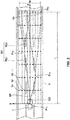
FIG. 2 is an explanatory diagram of route candidates. -
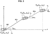
FIG. 3 is an explanatory diagram of the route candidates. -
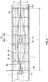
FIG. 4 is an explanatory diagram of the route candidates. -
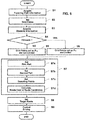
FIG. 5 is a flowchart showing computation executed by an ECU shown inFIG. 1 . - Hereafter, an embodiment of the present invention will be described referring to the accompanying drawings. In the figures, the same constitutional elements have the same reference characters attached, and duplicate descriptions for those are omitted here.
- Referring to
FIGS. 1 and2 , an outline of a drivingsupport system 100 as an example of a route candidate setting system according to the present invention will be described.FIG. 1 is a block diagram of the drivingsupport system 100, andFIG. 2 is an explanatory diagram of route candidates RC. - The driving
support system 100 is particularly installed at avehicle 1 and provides a driving support control to make thevehicle 1 travel along a target route. As shown inFIG. 1 , the drivingsupport system 100 particularly comprises an ECU (electric control device) 10, plural sensors, and plural control systems. The plural sensors include acamera 21, aradar 22, and other sensors to detect behavior of thevehicle 1 and driving operations by a passenger, such as avehicle speed sensor 23, anacceleration sensor 24, ayaw rate sensor 25, asteering angle sensor 26, anaccelerator sensor 27, and abrake sensor 28. Further, apositioning system 29 to detect a position of thevehicle 1 and anavigation system 30 are included. The plural control systems include anengine control system 31, abrake control system 32, and asteering control system 33. - A surrounding sonar to measure a distance between the
vehicle 1 and a surrounding structure and a position of the surrounding structure, a corner radar to measure approach of the surrounding structure to four corner portions of thevehicle 1, or an inner camera to pick up an image of a cabin inside of thevehicle 1 may be included as well. - The
ECU 10 is an example of a computing device according to the present invention. TheECU 10 is particularly constituted by a computer which comprises CPU, memories to memorize various programs, and input/output devices. TheECU 10 executes various computation based on signals received from the above-described plural sensors, and outputs control signals to theengine control system 31, thebrake control system 32, and thesteering control system 33 for respective appropriate operations of these systems. - The
ECU 10 executes computation for positioning on a traveling road based on traveling road information. The traveling road information is information on the traveling road where thevehicle 1 travels, which is acquired particularly by thecamera 21, theradar 22, thenavigation system 30, and/or so on. The traveling road information particularly includes information on a shape of the traveling road (linear, curved, curvature), a width of the traveling road, the number of lanes, a lane width, and the like, for example. -
FIG. 2 shows a state where thevehicle 1 travels on a travelingroad 5. TheECU 10 sets plural virtual grid points Gn (n = 1, 2, ... N) on the travelingroad 5 which exists on a forward side, in an advancing direction, of the vehicle 1 (or ahead of thevehicle 1 in the advancing direction) by the computation based on the traveling road information. When it is defined that a direction in which the travelingroad 5 extends is an x direction and a width direction of the travelingroad 5 is a y direction, the grid points Gn are arranged in a grid shape along the x direction and the y direction. - A range (area) where the
ECU 10 sets the grid points Gn expands forwardly along the travelingroad 5 over a distance L from thevehicle 1. This distance L is particularly calculated based on a speed of thevehicle 1 during execution of the computation by theECU 10. In the present embodiment, the distance L is particularly set at a predicted distance (L = V x t) which thevehicle 1 travels at the speed (V) for a specified fixed time t (3 seconds, for example). However, this distance L may be set at a specified fixed distance (100m, for example), or a function of a speed (and an acceleration). Further, a width W of the range where the grid points Gn are set is particularly set at a value which is nearly equal to a width of the travelingroad 5. Setting of the plural grid points Gn described above enables positioning on the travelingroad 5. - Herein, the grid points Gn are particularly arranged in a rectangular shape because the traveling
road 5 shown inFIG. 2 is liner (straight). However, since the grid points Gn are arranged along an extension direction of the traveling road, in a case where the traveling road includes a curved section, the grid points Gn are particularly arranged along curvature of the curved section. - Further, the
ECU 100 particularly executes computation for setting the route candidates RC (i.e., candidates of the target route for actual traveling of the vehicle 1) based on the traveling road information and obstacle information. Herein, the obstacle information is particularly information on an obstacle existing on the travelingroad 5 located in front of the vehicle 1 (e.g., a preceding vehicle, a parked vehicle, a pedestrian, a dropped object, and the like), a moving direction of the obstacle, a moving speed of the obstacle, and so on, which is acquired by thecamera 21 and theradar 22. - Moreover, the
ECU 10 sets the plural route candidates RC by the route search using the State Lattice method. In the State Lattice method, the plural route candidates RC are set such that these branch off from the position of thevehicle 1 toward the grid points Gn located on a forward side, in the advancing direction, of thevehicle 1.FIG. 2 shows a part of the plural route candidates RC set by theECU 10. - The
ECU 10 particularly selects one of the route candidates RC which has a minimum route cost based on a specified condition. Specifically, as shown inFIG. 2 , theECU 10 sets plural sampling points SP along each of the route candidates RC and calculates the route cost at each of the sampling points SP. Then, theECU 10 particularly selects one of the route candidates RC which has the minimum route cost and sets this selected route candidate RC as the target route. - It is anticipated that there are various ways to select the one of the route candidates RC as the target route. The route cost is merely one example for selecting the one of the route candidates RC as the target route.
- Moreover, the
ECU 10 particularly outputs the control signals to theengine control system 31, thebrake control system 32, and/or thesteering control system 33 so that thevehicle 1 can travel along the target route set as described above. - The
camera 21 is an example of a traveling road information acquisition device according to the present invention and also an example of an obstacle information acquisition device according to the present invention. Thecamera 21 particularly picks up images around thevehicle 1 and outputs data of the images picked up. TheECU 10 particularly specifies objects (e.g., the preceding vehicle, the parked vehicle, the pedestrian, the traveling road, lanes (lane borders, white lines, yellow lines), traffic signals, traffic signs, stop lines, intersections, obstacles) based on the image data received from thecamera 21. Herein, theECU 10 may acquire information on the objects from outside by means of transportation infrastructure, inter-vehicle communication, or the like. Thereby, a kind of each object, a relative position of each object, a moving direction of each object, and others are specified. - The
radar 22 is an example of the traveling road information acquisition device according to the present invention and also an example of the obstacle information acquisition device according to the present invention. Theradar 22 particularly measures each position and speed of the objects (particularly, the preceding vehicle, the parked vehicle, the pedestrian, the dropped object on the travelingroad 5, and the like). A millimeter-wave radar is usable as theradar 22, for example. Theradar 22 particularly transmits radio waves in the advancing direction of thevehicle 1 and receives reflected waves from the object. Theradar 22 particularly measures the distance between thevehicle 1 and the object (e.g., an inter-vehicle distance) or the relative speed of the object to thevehicle 1 based on the transmission waves and the reception waves. In the present embodiment, the above-described distance or relative speed may be measured by using a razor radar, a supersonic sensor, or the like in place of theradar 22. Further, a position and speed measuring device may be constituted by using plural sensors. - The
vehicle speed sensor 23 particularly detects an absolute speed of thevehicle 1. Theacceleration sensor 24 particularly detects an acceleration of the vehicle 1 (a longitudinal acceleration/deceleration, a lateral acceleration/deceleration). Theyaw rate sensor 25 particularly detects a yaw rate of thevehicle 1. Thesteering angle sensor 26 particularly detects a rotational angle of a steering wheel (i.e., a steering angle) of thevehicle 1. TheECU 10 is capable of acquiring a yaw angle of the vehicle 1 (i.e., an angle of a longitudinal direction of thevehicle 1 relative to an x coordinate which will be described later) by executing specified computation based on the absolute speed detected by thevehicle speed sensor 23 and the steering angle detected by thesteering angle sensor 26. Theaccelerator sensor 27 detects a pressing quantity of an accelerator. Thebrake sensor 28 detects a pressing quantity of a brake pedal. - The
positioning system 29 is particularly a GPS system and/or a gyro system and detects a position (location) of the vehicle 1 (i.e., present (current) vehicle-position information). Thenavigation system 30 particularly stores map information therein and is capable of providing the map information to theECU 10. TheECU 10 specifies roads, intersections, traffic signals, structures and others which exist around the vehicle 1 (in the advancing direction, particularly) based on the map information and the present vehicle-position information. The map information may be stored inside theECU 10. - The
engine control system 31 particularly controls an engine of thevehicle 1. TheECU 10 outputs the control signal to theengine control system 31 in order to change an engine output in a case where the acceleration or deceleration of thevehicle 1 is necessary. - The
brake control system 32 particularly controls a brake device of thevehicle 1. TheECU 10 outputs the control signal to thebrake control system 31 in order to generate a braking force in a case where the acceleration of thevehicle 1 is necessary. - The
steering control system 33 particularly controls a steering device of thevehicle 1. TheECU 10 outputs the control signal to thesteering control system 33 in order to change a steering direction in a case where changing of the advancing direction of thevehicle 1 is necessary. - Next, the computation for setting the route candidates RC will be described referring to FGS. 2 - 4.
FIGS. 3 and4 are explanatory diagrams of the route candidates RC.FIG. 2 shows the route candidates RC in a case where no obstacle exists on the travelingroad 5 in the advancing direction of thevehicle 1.FIG. 4 shows the route candidates RC in a case where the obstacle exists on the travelingroad 5 in the advancing direction of thevehicle 1. - Each of the route candidates RC comprises a first part RC1 and a second part RC2 as shown in
FIGS. 2 - 4 . - The first part RC1 extends from a start point P1s up to a terminal point P1e. The start point P1s is the position of the
vehicle 1 during the execution of the computation. The start point P1s is represented by coordinates (x1s, y1s). In an example shown inFIGS. 2 - 4 , since thevehicle 1 is located at the origin of the x, y coordinates, the coordinates of the start point P1s is (0, 0). The terminal point P1e is the grid point Gn which is specified by excluding a terminal point P2e (which will be described later) of the second part RC2 from the plural grid points Gn. The coordinates of the terminal point P1e is represented by (x1e, y1e). - The second part RC2 is continuous to the first part RC1 at the terminal point P1e and extends up to its terminal point P2e. That is, the terminal point P1e of the first part RC1 is also the start point of the second part RC2. The terminal point P2e is the grid point Gn among the plural grid points Gn which is located furthest from the
vehicle 1 in the x direction. The coordinates of the terminal point P2e is represented by (x2e, y2e). - First, the route candidates RC in a case where no obstacle exits on the traveling
road 5 in the advancing direction of thevehicle 1 will be described. In this case, theECU 10 sets all of the grid points Gn which are specified by excluding the plural grid points Gn furthest from thevehicle 1 in the x direction as the terminal points P1e. TheECU 10 sets the first parts RC1 extending from the start points P1s up to these set terminal points P1e. - Next, the
ECU 10 sets the plural grid points Gn furthest from thevehicle 1 in the x direction as the terminal points P2e, and sets the second parts RC2 extending from the terminal points P1e of the first parts RC1 up to these set terminal points P2e. TheECU 10 sets the curved lines comprising the first parts RC1 and the second parts RC2 as the route candidates RC. - The
ECU 10 provisionally provides a quintic function having x coordinate as a variable and y coordinate as a curved line which is set as the first part RC1 as particularly shown in the following expression f1. The expression f1 is an example of a first function according to the present invention. The curved line which is plotted in the x, y coordinates based on the expression f1 is an example of a first curved line according to the present invention.
[formula 1]
- Herein, a1 - f1 are unknown coefficients. It is necessary to decide the coefficients a1 - f1 by solving at least six relational expressions in order to specifically provide the curved line extending from the start point up P1s up to the terminal point P1e. Accordingly, the
ECU 10 particularly prepares the following expressions f2 - f4 which are respectively obtained by first-order - third-order differentiations of the expression f1.
[formula 2]


- The coordinates (x1s, y1s) of the start point P1s and the coordinates (x1e, y1e) of the terminal point P1e meet the expression f1, respectively. Accordingly, the
ECU 10 is capable of obtaining the following relational expressions f5, f6.
[formula 3]

- In the following description, an angle of a
straight line 1L extending along the longitudinal direction of thevehicle 1 relative to the x coordinate as show inFIG. 3 will be referred to as the "yaw angle." Further, the yaw angle at the start point P1s is expressed by His and the yaw angle at the terminal point P1e of is expressed by H1e. An unit of H1s, H1e is radian. - The x coordinate (x1s) of the start point P1s and a tangent of the yaw angle H1s at the start point P1s meet relationships of the expression f2. Further, the x coordinate (x1e) of the terminal point P1e and a tangent of the yaw angle H1e at the terminal point P1e meet relationships of the expression f2 as well. Accordingly, the
ECU 10 is capable of obtaining the following relational expressions f7, f8.
[formula 4]

- Since the expression f3 represents a changing rate of y' to x, this expression f3 is correlated with a yaw angle speed. Accordingly, the x coordinate (x1s) of the start point P1s and a yaw angle speed K1s at the start point P1s linearly meet relationships of the expression f3. Further, the x coordinate (x1e) of the terminal point P1e and a yaw angle speed K1e at the terminal point P1e linearly meet relationships of the expression f3 as well. Accordingly, the
ECU 10 is capable of obtaining the following relational expressions f9, f10.
[formula 5]

- Further, since the expression f4 represents a changing rate of y" to x, this expression f4 is correlated with a yaw angle acceleration. Accordingly, the x coordinate (x1s) of the start point P1s and a yaw angle acceleration K1s' at the start point P1s linearly meet relationships of the expression f4. Further, the x coordinate (x1e) of the terminal point P1e and a yaw angle acceleration K1e' a at the terminal point P1e linearly meet relationships of the expression f4 as well. Accordingly, the
ECU 10 is capable of obtaining the following relational expressions f11, f12.
[formula 6]

- The
ECU 10 properly sets plural border conditions which represent respective states of the vehicle 1 (i.e., the coordinates, the yaw angle, the yaw angle speed, the yaw angle acceleration) at the start point P1s and the terminal point P1e. TheECU 10 decides the coefficients a1 - f1 by solving at least six relational expressions among the eight relational expressions f5 - f12 with applications of these border conditions. Thereby, theECU 10 is capable of specifically providing the curved line set as the first part RC1 which extends from the start point P1s up to the terminal point P1e. - The
ECU 10 provisionally provides a cubic function having x coordinate as a variable and y coordinate as a curved line which is set as the second part RC2 as particularly shown in the following expression f13. The expression f13 is an example of a second function according to the present invention. The curved line which is plotted in the x, y coordinates based on the expression f13 is an example of a second curved line according to the present invention.
[formula 7]
- Herein, a2 - d2 are unknown coefficients. It is necessary to decide the coefficients a2 - d2 by solving at least four relational expressions in order to specifically provide the curved line extending from the start point up P1e up to the terminal point P2e. Accordingly, the
ECU 10 prepares the following expressions fl4, f 15 which are respectively obtained by first-order and second-order differentiations of the expression fl3.
[formula 8]

- The coordinates (x1e, y1e) of the terminal point P1e and the coordinates (x2e, y2e) of the terminal point P2e meet the expression f13, respectively. Accordingly, the
ECU 10 is capable of obtaining the following relational expressions f16, f17.
[formula 9]

- Further, the x coordinate (x1e) of the terminal point P1e and a tangent of the yaw angle H1e at the terminal point P1e meet relationships of the expression f14. Further, the x coordinate (x2e) of the terminal point P2e and a tangent of the yaw angle H2e at the terminal point P2e meet relationships of the expression f14 as well. An unit of H1e, H2e is radian. Accordingly, the
ECU 10 is capable of obtaining the following relational expressions f18, f19.
[formula 10]

- Further, since the expression f15 represents the changing rate of y' to x, this expression f15 is correlated with the yaw angle speed. Accordingly, the x coordinate (x1e) of the start point P1e and a yaw angle speed K1e at the terminal point P1e linearly meet relationships of the expression f15. Further, the x coordinate (x2e) of the terminal point P2e and a yaw angle speed K2e at the terminal point P2e linearly meet relationships of the expression fl5 as well. Accordingly, the
ECU 10 is capable of obtaining the following relational expressions f20, f21.
[formula 11]

- The
ECU 10 properly sets plural border conditions which represent respective states of the vehicle 1 (i.e., the coordinates, the yaw angle, the yaw angle speed) at the terminal point P1e and the terminal point P2e. TheECU 10 decides the coefficients a2 - d2 by solving at least four relational expressions among the six relational expressions f16 - f21 with applications of these border conditions. Thereby, theECU 10 is capable of specifically providing the curved line set as the second part RC2 which extends from the terminal point P1e up to the terminal point P2e. - Next, the route candidate RC in a case where an obstacle exists on the traveling
road 5 in the advancing direction of thevehicle 1 will be described.FIG. 4 shows a case where a precedingvehicle 1A as the obstacle exists on the travelingroad 5 in the advancing direction of thevehicle 1. - This case is the same as the above-described case where no obstacle exists in terms of the route candidate RC comprising the first part RC1 set by using the quintic function and the second part RC2 set by using the cubic function. The case is, however, different from the case where no obstacle exists in terms of the grid points Gn which are set as the terminal points P1e of the first parts RC1 being limited.
- Specifically, as shown in
FIG. 4 , in the case where the precedingvehicle 1A exists in a range where the grid points Gn are set, theECU 10 does not provide any curved line having the terminal point P1e which corresponds to the grid point Gn which is located on the forward side, in the advancing direction of thevehicle 1, of the precedingvehicle 1A and any curved line having the start point which corresponds to this grid point Gn. Thus, the route candidate RC which comprises the first part RC1 having the terminal point P1e which corresponds to the grid point Gn located on the forward side, in the advancing direction of thevehicle 1, of the precedingvehicle 1A and the second part RC2 having the start point which corresponds to this grid point Gn is not set. - More specifically, the
ECU 10 provides only the curved line having the terminal point P1e which corresponds to the grid point Gn located in the vicinity of the precedingvehicle 1A and the curved line having the start point which corresponds to this grid point Gn in the case where the precedingvehicle 1A exists in the range where the grid points Gn are set. Accordingly, the route candidate RC comprising the first part RC1 having the terminal point P1e which corresponds to the grid point Gn located in the vicinity of the precedingvehicle 1A and the second part RC2 having the start point which corresponds to this grid point Gn is set only. - Particularly, the
ECU 10 provides only the curved line having the terminal point P1e which corresponds to the grid point Gn between the precedingvehicle 1A and thevehicle 1, and the curved line having the start point which corresponds to this grid point Gn in the case where the precedingvehicle 1A exists in the range where the grid points Gn are set. Accordingly, the route candidate RC comprising the first part RC1 having the terminal point P1e which corresponds to the grid point Gn between the precedingvehicle 1A and thevehicle 1 and the second part RC2 having the start point which corresponds to this grid point Gn is set only. - Next, the computation executed by the
ECU 10 in the driving support control will be described referring toFIG. 5. FIG. 5 is particularly a flowchart showing the computation executed by theECU 10. TheECU 10 executes the computation shown inFIG. 5 repeatedly (e.g., at every 0.05 - 0.2 sec.). - First, the
ECU 10 particularly acquires the traveling road information from thecamera 21, theradar 22, and thenavigation system 30 in step S1. - Next, in step S2, the
ECU 10 particularly specifies the shape of the traveling road 5 (e.g., an extension direction of the travelingroad 5, a width of the traveling road 5) and sets the plural grid points Gn (n = 1, 2, ... N) on the travelingroad 5. TheECU 10 sets the grid points Gn every 10m in the x direction and every 0.875m in the y direction, for example. - Then, in step S3, the
ECU 10 acquires the obstacle information from thecamera 21 and theradar 22. That is, theECU 10 particularly acquires information on the obstacle existing on the travelingroad 5 located in front of thevehicle 1, the moving direction of the obstacle, the moving speed of the obstacle, and so on. - Next, in step S4, the
ECU 10 particularly determines whether the obstacle exists on the travelingroad 5 in the advancing direction of thevehicle 1. Specifically, theECU 10 determines whether the preceding vehicle, the parked vehicle, the pedestrian or the like exist in the range where the grid points Gn are set based on the obstacle information acquired in the step S3. In a case where it is determined that no obstacle exists on the travelingroad 5 in the advancing direction of the vehicle 1 (NO: in the step S4), theECU 10 proceeds to step S5. - Then, in the step S5, the
ECU 10 particularly decides that the grid points Gn which are set as the terminal points P1e of the first parts RC1 of the route candidate RC are not limited. That is, theECU 10 sets all of the grid points Gn which are specified by excluding the plural grid points Gn furthest from thevehicle 1 in the x direction as the terminal points P1e as shown inFIG. 2 . - A step S7 includes setting of the route candidates RC (steps S7a, S7b), setting of the sampling points SP (step S7c), and calculation of the route cost of each of the route candidates RC (step S7d).
- In the step S7a, the
ECU 10 particularly sets the first part RC1 extending from the start point P1s up to the all of the grid points Gn set as the terminal point P1e. The start point P1s is the position of thevehicle 1 during the execution of the computation as described above. - Then, in the step S7b, the
ECU 10 particularly sets the second parts RC2 extending from the terminal points P1e of the first parts RC1 up to the all of the grid points Gn set as the terminal points P2e. The terminal points P2e are the plural grid points Gn furthest from thevehicle 1 in the x direction as described above. - The plural first parts RC1 are set in the step S7a, and the plural second parts RC2 continuous from the first parts RC1 are set in the step S7b. The many route candidates RC are set on the traveling
road 5 by these plural first and second parts RC1, RC2 being set. - Next, in the step S7c, the
ECU 10 particularly sets the plural sampling points SP (seeFIG. 2 ). The sampling points SP are set at regular intervals (e.g., every 0.2m) in the x direction along the route candidates RC set in the steps S7a, S7b. - Subsequently, in the step S7d, the
ECU 10 particularly calculates the route cost at each of the sampling points SP of the route candidates RC. The route cost includes costs related to the speed, the acceleration, the lateral acceleration, the route changing rate, the obstacle, and so on. These costs can be properly set. Schematically, the route cost includes a traveling cost and a safety cost. For example, in a case where the vehicle travels on the liner (straight) route, the traveling cost is small because of a short traveling distance. In a case where the vehicle travels on a route to avoid the obstacle or the like, however, the traveling cost is relatively large because the traveling distance is longer. Further, the traveling const increases as the lateral acceleration becomes large. - The
ECU 10 particularly stores the largest traveling cost among the route costs calculated for the sampling points SP of the route candidates RC in a memory, not illustrated, as the route cost of the route candidates RC. - The
ECU 10 particularly executes the calculation of the step S7 for all of the plural grid points Gn set as the terminal points P1e in the step S5. - Next, in step S8, the
ECU 10 particularly sets the target route. Specifically, theECU 10 selects the route candidate RC having the smallest route cost, and sets this route candidate RC as the target route. - Then, in step S9, the
ECU 10 particularly outputs the control signals to theengine control system 31, thebrake control system 32, and thesteering control system 33 so that thevehicle 1 can travel along this target route. - Meanwhile, in a case where it is determined in the step S4 that the obstacle exists on the traveling
road 5 in the advancing direction of the vehicle 1 (YES: in the step S4), theECU 10 proceeds to step S6. - In the step S6, the
ECU 10 particularly decides that the grid points Gn which are set as the terminal points P1e of the first parts RC1 of the route candidate RC are limited. That is, theECU 10 sets only the grid points Gn located in the vicinity of the precedingvehicle 1A as the obstacle as the terminal points P1e as shown inFIG. 4 . - In this case, the
ECU 10 particularly executes the calculation of the step S7 for all of the plural grid points Gn set as the terminal points P1e in the step S6. Herein, the total number of the route candidates RC set in the steps S7a, S7b is less than that of the route candidates RC in the case where no obstacle exists on the travelingroad 5 in the advancing direction of the vehicle 1 (NO: in the step S4). Thereby, the computing load of theECU 10 is reduced. - Further, in the case where it is determined that the obstacle exists on the traveling
road 5 in the advancing direction of the vehicle 1 (YES: in the step S4), the total number of the route candidates RC set in the step S7c is also less than that of the route candidates RC in the case where no obstacle exists on the travelingroad 5 in the advancing direction of the vehicle 1 (NO: in the step S4). Accordingly, the load of calculation of the route cost in the step S7d is reduced. - Hereafter, the operation of the driving
support system 100 of the present embodiment will be described. - According to the present system, the
ECU 10 as the computing device sets the first curved line as the route candidate RC for the close range which is positioned relatively closely to thevehicle 1 and sets the second curved line as the route candidate RC for the far range which is far from the close range. While the first curved line represented by the quintic function can set the precise route candidate RC which is capable of meeting many requirements, the computing load in providing the first curved line is large. Meanwhile, the second curved line represented by the cubic function having the relatively low degree does not cope with many requirements like the first curved line, but the computing load in providing the second curved line is properly small. TheECU 10 can reduce the computing load in setting the route candidate RC by setting the second curved line as part of the route candidate RC. - Herein, in a case where the obstacle exists on the traveling
road 5, it is preferable that the route candidate RC for a range from thevehicle 1 to the obstacle be set precisely by the first curved line so that various requirements, such as vehicle's collision avoidance with the obstacle or less discomfort that passengers may feel in operation for this vehicle's collision avoidance, can be met. Meanwhile, the route candidate RC for a range which is far from the obstacle does not require such precise setting like the route candidate RC for the range from thevehicle 1 to the obstacle. - Thus, according to the present system, in the case where the obstacle is detected by the
camera 21 and theradar 22, theECU 10 does not provide the first curved line having the terminal point P1e which corresponds to the grid point Gn located on the forward side, in the advancing direction of thevehicle 1, of the obstacle and the second curved line having the start point which corresponds to this grid point Gn. Thereby, the present system can properly reduce the computing load in setting the route candidates RC, meeting the requirements, such as vehicle's collision avoidance with the obstacle or less discomfort that passengers may feel in operation for this vehicle's collision avoidance. - Further, the
ECU 10 provides only the first curved line having the terminal point P1e which corresponds to the grid point Gn located in the vicinity of the obstacle and the second curved line having the start point which corresponds to this grid point Gn in the case where the obstacle is detected by thecamera 21 and theradar 22. The present system can more properly reduce the computing load in setting the route candidates, meeting the requirements, such as vehicle's collision avoidance with the obstacle or less discomfort that passengers may feel in operation for this vehicle's collision avoidance. - Herein, the first function is the quintic function having the x coordinate as the variable. According to the present system, the relational expressions correlated with the yaw angle, the yaw angle speed, and the yaw angle acceleration of the
vehicle 1 can be respectively obtained by first-order - third-order differentiations of the quintic function with the x coordinate. The yaw angle, the yaw angle speed and the yaw angle acceleration of thevehicle 1 can be evaluated by these relational expressions. Consequently, the present system can set the route candidates RC to reduce the discomfort that passengers may feel, considering behavior of thevehicle 1 in a yaw direction. - Meanwhile, the second function is the cubic function having the x coordinate as a variable. According to the present system, the relational expressions correlated with the yaw angle and the yaw angle speed of the vehicle can be respectively obtained by first-order and second-order differentiations of the cubic function with the x coordinate. The yaw angle and the yaw angle speed of the vehicle can be evaluated by these relational expressions. Consequently, the present system can set the route candidates RC to reduce the discomfort that passengers may feel, considering the behavior of the
vehicle 1 in the yaw direction. - While the embodiment of the present invention has been described referring to the specific examples, the present invention should not be limited to the above-described examples and any other modifications or improvements may be applied within the scope of the present invention.
Claims (15)
- A route candidate setting system (100) for setting candidates (RC) of a traveling route of a vehicle (1), comprising:a traveling-road information acquisition device (21, 22) configured to acquire traveling-road information on a traveling road (5) of the vehicle (1);an obstacle information acquisition device (21, 22) configured to acquire obstacle information on an obstacle (1A) existing on the traveling road (5); anda computing device (10) to execute computation of setting the candidates (RC) of the traveling route of the vehicle (1) based on the traveling-road information acquired by the traveling-road information acquisition device (21, 22) and the obstacle information acquired by obstacle information acquisition device (21, 22),whereinthe computing device (10) is configured, when it is defined that a direction in which the traveling road (5) extends is an x direction and a width direction of the traveling road (5) is a y direction, to:set plural grid points (Gn) arranged in a grid shape on the traveling road (5); andprovide a first curved line (RC1) and a second curved line (RC2),the first curved line (RC1) extends from a start point (P1s) to a terminal point (P1e),the start point (P1s) of the first curved line (RC1) corresponds to a position of the vehicle (1) during execution of the computation by the computing device (10),the terminal point (P1e) of the first curved line (RC1) corresponds to a grid point (Gn) located ahead of the vehicle (1) in an advancing direction,in the first curved line (RC1), y coordinate is represented by a first function having x coordinate as a variable,the second curved line (RC2) extends, from a start point corresponding to the terminal point (P1e) of the first curved line (RC1), up to a terminal point (P2e),the terminal point (P2e) of the second curved line (RC2) corresponds to another grid point (Gn) located ahead of the start point of the second curved line (RC2) in the advancing direction of the vehicle (1),in the second curve line (RC2), y coordinate is represented by a second function having x coordinate as a variable,a degree of the second function is lower than that of the first function,the computing device (10) is configured to set the first curved line (RC1) and the second curved line (RC2) as the candidate (RC) of the traveling route of the vehicle (1),the computing device (10) is configured not to provide, in a case where the obstacle (1A) is detected by the obstacle information acquisition device (21, 22), the first curved line (RC1) having the terminal point (P1e) which corresponds to the grid point (Gn) located ahead of the obstacle (1A) in the advancing direction of the vehicle (1) and the second curved line (RC2) having the start point which corresponds to the grid point (Gn) located ahead of the obstacle (1A) in the advancing direction of the vehicle (1).
- The route candidate setting system (100) of claim 1, wherein the computing device (10) is configured to provide only the first curved line (RC1) having the terminal point (P1e) which corresponds to the grid point (Gn) located in the vicinity of the obstacle (1A) and the second curved line (RC2) having the start point which corresponds to the grid point (Gn) located in the vicinity of the obstacle (1A), in the case where the obstacle (1A) is detected by the obstacle information acquisition device (21, 22).
- The route candidate setting system (100) of claim 1 or 2, wherein the computing device (10) is configured to provide only the first curved line (RC1) having the terminal point (P1e) which corresponds to the grid point (Gn) located between the obstacle (1A) and the vehicle (1) and the second curved line (RC2) having the start point which corresponds to the grid point (Gn) located between the obstacle (1A) and the vehicle (1), in the case where the obstacle (1A) is detected by the obstacle information acquisition device (21, 22).
- The route candidate setting system (100) of any one of the preceding claims, wherein the first function is a quintic function having x coordinate as a variable.
- The route candidate setting system (100) of any one of the preceding claims, wherein in the first curved line (RC1), y coordinate is represented as follows:

- The route candidate setting system (100) of claim 5, wherein the computing device (10) is configured to calculate the coefficients of a1, b1, c1, d1, e1, and f1.
- The route candidate setting system (100) of any one of the preceding claims, wherein the computing device (10) is configured to differentiate the first function thereby obtaining the first curved line (RC1).
- The route candidate setting system (100) of any one of the preceding claims, wherein the second function is a cubic function having x coordinate as a variable.
- The route candidate setting system (100) of any one of the preceding claims, wherein in the second curved line (RC2), y coordinate is represented as follows:

- The route candidate setting system (100) of claim 9, wherein the computing device (10) is configured to calculate the coefficients of a2, b2, c2, and d2.
- The route candidate setting system (100) of any one of the preceding claims, wherein the computing device (10) is configured to differentiate the second function thereby obtaining the second curved line (RC2).
- A vehicle comprising the route candidate setting system (100) of any one of the preceding claims.
- The vehicle of claim 12, wherein
the computing device (10) is configured to set a plurality of the candidates (RC) of the traveling route of the vehicle (1),
the vehicle (1) further comprising a driving support system configured to select one of the candidates (RC) and control the vehicle (1) to travel along the selected one of the candidates (RC). - A route candidate setting method of setting candidates (RC) of a traveling route of a vehicle (1), comprising steps of:acquiring traveling-road information on a traveling road (5) of the vehicle (1);acquiring obstacle information on an obstacle (1A) existing on the traveling road (5); andexecuting computation of setting the candidates (RC) of the traveling route of the vehicle (1) based on the traveling-road information and the obstacle information,wherein the step of executing the computation includes, when it is defined that a direction in which the traveling road (5) extends is an x direction and a width direction of the traveling road is a y direction, steps of:setting plural grid points (Gn) on the traveling road (5); andproviding a first curved line (RC1) and a second curved line (RC2),whereinthe first curved line (RC1) extends from a start point (P1s) to a terminal point (P1e),the start point (P1s) of the first curved line (RC1) corresponds to a position of the vehicle (1) during execution of the computation,the terminal point (P1e) of the first curved line (RC1) corresponds to a grid point (Gn) located ahead of the vehicle (1) in an advancing direction,in the first curved line (RC1), y coordinate is represented by a first function having x coordinate as a variable,the second curved line (RC2) extends from a start point corresponding to the terminal point (P1e) of the first curved line (RC1) up to a terminal point (P2e),the terminal point (P2e) of the second curved line (RC2) corresponds to another grid point (Gn) located ahead of the start point of the second curved line (RC2) in the advancing direction of the vehicle (1),in the second curved line (RC2), y coordinate is represented by a second function having x coordinate as a variable,a degree of the second function is lower than that of the first function,the step of executing the computation includes, setting the first curved line (RC1) and the second curved line (RC2) as the candidate (RC) of the traveling route of the vehicle (1), andthe step of executing the computation includes not providing, in a case where the obstacle (1A) is detected, the first curved line (RC1) having the terminal point (P1e) which corresponds to the grid point (Gn) located ahead of the obstacle (1A) in the advancing direction of the vehicle (1) and the second curved line (RC2) having the start point which corresponds to the grid point (Gn) located ahead of the obstacle (1A) in the advancing direction of the vehicle (1).
- A computer program product comprising computer-readable instructions which, when loaded and executed on a suitable system, perform a method of claim 14.
Applications Claiming Priority (1)
| Application Number | Priority Date | Filing Date | Title |
|---|---|---|---|
| JP2018224934A JP7183521B2 (en) | 2018-11-30 | 2018-11-30 | Route candidate setting system and route candidate setting method |
Publications (1)
| Publication Number | Publication Date |
|---|---|
| EP3660459A1 true EP3660459A1 (en) | 2020-06-03 |
Family
ID=68655295
Family Applications (1)
| Application Number | Title | Priority Date | Filing Date |
|---|---|---|---|
| EP19211096.3A Withdrawn EP3660459A1 (en) | 2018-11-30 | 2019-11-25 | Route candidate setting system, vehicle, route candidate setting method, and computer program product |
Country Status (3)
| Country | Link |
|---|---|
| US (1) | US11262202B2 (en) |
| EP (1) | EP3660459A1 (en) |
| JP (1) | JP7183521B2 (en) |
Families Citing this family (6)
| Publication number | Priority date | Publication date | Assignee | Title |
|---|---|---|---|---|
| JP7725820B2 (en) | 2020-05-19 | 2025-08-20 | 東ソー株式会社 | Silicide alloy material and element using same |
| CN112124295B (en) * | 2020-09-29 | 2024-01-05 | 北京易控智驾科技有限公司 | Unmanned vehicles and their terminal lateral steady-state control methods and electronic devices |
| CN112393728B (en) * | 2020-10-23 | 2022-05-31 | 浙江工业大学 | Mobile robot path planning method based on A-algorithm and RRT-algorithm |
| CN114815791B (en) * | 2021-01-18 | 2025-06-17 | 浙江菜鸟供应链管理有限公司 | Drivable space planning method and device |
| CN113486836B (en) * | 2021-07-19 | 2023-06-06 | 安徽江淮汽车集团股份有限公司 | Automatic driving control method for low-pass obstacle |
| CN114987498B (en) * | 2022-06-10 | 2023-01-20 | 清华大学 | Anthropomorphic trajectory planning method and device for automatic driving vehicle, vehicle and medium |
Citations (3)
| Publication number | Priority date | Publication date | Assignee | Title |
|---|---|---|---|---|
| WO2013051081A1 (en) | 2011-10-03 | 2013-04-11 | トヨタ自動車株式会社 | Vehicle driving support system |
| DE102013221369A1 (en) * | 2013-10-22 | 2015-04-23 | Robert Bosch Gmbh | Procedure for bypassing an obstacle |
| US9229453B1 (en) * | 2014-08-29 | 2016-01-05 | GM Global Technology Operations LLC | Unified motion planner for autonomous driving vehicle in avoiding the moving obstacle |
Family Cites Families (15)
| Publication number | Priority date | Publication date | Assignee | Title |
|---|---|---|---|---|
| DE19539641C2 (en) * | 1995-10-25 | 2000-02-17 | Daimler Chrysler Ag | Method and device for traffic situation-dependent vehicle route guidance |
| US6545288B1 (en) * | 2001-03-08 | 2003-04-08 | Lsi Logic Corporation | Gridless router using maze and line probe techniques |
| US7069531B1 (en) * | 2002-07-15 | 2006-06-27 | Cadence Design Systems, Inc. | Method and apparatus for identifying a path between source and target states in a space with more than two dimensions |
| US9318023B2 (en) * | 2011-08-31 | 2016-04-19 | GM Global Technology Operations LLC | System and method for collision avoidance maneuver path determination with jerk limit |
| US9549253B2 (en) * | 2012-09-26 | 2017-01-17 | Foundation for Research and Technology—Hellas (FORTH) Institute of Computer Science (ICS) | Sound source localization and isolation apparatuses, methods and systems |
| EP2826687B1 (en) * | 2013-07-16 | 2019-03-06 | Honda Research Institute Europe GmbH | Technique for lane assignment in a vehicle |
| US9174672B2 (en) * | 2013-10-28 | 2015-11-03 | GM Global Technology Operations LLC | Path planning for evasive steering maneuver in presence of target vehicle and surrounding objects |
| US9199668B2 (en) * | 2013-10-28 | 2015-12-01 | GM Global Technology Operations LLC | Path planning for evasive steering maneuver employing a virtual potential field technique |
| CN104486715B (en) * | 2014-11-26 | 2018-03-13 | 南京邮电大学 | A kind of mobile sensor network cluster-dividing method based on geographical location information |
| US10115024B2 (en) * | 2015-02-26 | 2018-10-30 | Mobileye Vision Technologies Ltd. | Road vertical contour detection using a stabilized coordinate frame |
| US20200033871A1 (en) | 2016-09-29 | 2020-01-30 | Honda Motor Co., Ltd. | Vehicle control device |
| CN110121449B (en) | 2017-01-11 | 2022-06-28 | 本田技研工业株式会社 | Vehicle control device, vehicle control method, and storage medium |
| JP6562386B2 (en) | 2017-02-24 | 2019-08-21 | マツダ株式会社 | Vehicle driving support system and method |
| JP6573643B2 (en) * | 2017-03-27 | 2019-09-11 | 株式会社Subaru | Vehicle travel control device |
| US11110922B2 (en) * | 2018-11-05 | 2021-09-07 | Zoox, Inc. | Vehicle trajectory modification for following |
-
2018
- 2018-11-30 JP JP2018224934A patent/JP7183521B2/en active Active
-
2019
- 2019-11-25 EP EP19211096.3A patent/EP3660459A1/en not_active Withdrawn
- 2019-11-25 US US16/694,902 patent/US11262202B2/en active Active
Patent Citations (4)
| Publication number | Priority date | Publication date | Assignee | Title |
|---|---|---|---|---|
| WO2013051081A1 (en) | 2011-10-03 | 2013-04-11 | トヨタ自動車株式会社 | Vehicle driving support system |
| US20140244114A1 (en) | 2011-10-03 | 2014-08-28 | Toyota Jidosha Kabushiki Kaisha | Driving assistance system for vehicle |
| DE102013221369A1 (en) * | 2013-10-22 | 2015-04-23 | Robert Bosch Gmbh | Procedure for bypassing an obstacle |
| US9229453B1 (en) * | 2014-08-29 | 2016-01-05 | GM Global Technology Operations LLC | Unified motion planner for autonomous driving vehicle in avoiding the moving obstacle |
Also Published As
| Publication number | Publication date |
|---|---|
| JP2020087267A (en) | 2020-06-04 |
| US11262202B2 (en) | 2022-03-01 |
| US20200173794A1 (en) | 2020-06-04 |
| JP7183521B2 (en) | 2022-12-06 |
Similar Documents
| Publication | Publication Date | Title |
|---|---|---|
| US11262202B2 (en) | Route candidate setting system and route candidate setting method | |
| US11198439B2 (en) | Vehicle control device, vehicle control method, and storage medium | |
| JP7180426B2 (en) | vehicle control system | |
| EP3683550A1 (en) | Vehicle driving assistance system and method | |
| EP3715791A1 (en) | Vehicle driving support system, method, computer-program product, and vehicle | |
| US11608062B2 (en) | Vehicle control method and vehicle control device | |
| EP3486132A1 (en) | Vehicle control device | |
| EP3683115A1 (en) | Vehicle driving assistance system and vehicle driving assistance method | |
| EP4397553B1 (en) | Vehicle control method and vehicle control device | |
| EP3693704A1 (en) | Vehicle driving assistance system and vehicle driving assistance method | |
| EP3549837A1 (en) | Vehicle control apparatus | |
| EP4266286B1 (en) | Vehicle motion control device and vehicle motion control method | |
| EP3985641B1 (en) | Travel assistance method and travel assistance device | |
| EP3715203A1 (en) | Vehicle driving support system, method, computer-program product, and vehicle | |
| EP3626570B1 (en) | Driving assistance method and driving assistance apparatus | |
| US20220315050A1 (en) | Vehicle control device, route generation device, vehicle control method, route generation method, and storage medium | |
| JP7252513B2 (en) | Vehicle driving support system | |
| EP3683546A2 (en) | Vehicle driving assistance system and vehicle driving assistance method | |
| EP4112404B1 (en) | Vehicle control method and vehicle control device | |
| JP7393721B2 (en) | Driving route generation system and vehicle driving support system | |
| JP7373118B2 (en) | Driving route generation system and vehicle driving support system | |
| JP7183520B2 (en) | Route candidate setting system and route candidate setting method | |
| JP2020166123A (en) | Map data creation method and map data creation device | |
| JP7375596B2 (en) | Driving route generation system and vehicle driving support system | |
| JP7209946B2 (en) | Vehicle driving support system |
Legal Events
| Date | Code | Title | Description |
|---|---|---|---|
| PUAI | Public reference made under article 153(3) epc to a published international application that has entered the european phase |
Free format text: ORIGINAL CODE: 0009012 |
|
| STAA | Information on the status of an ep patent application or granted ep patent |
Free format text: STATUS: THE APPLICATION HAS BEEN PUBLISHED |
|
| AK | Designated contracting states |
Kind code of ref document: A1 Designated state(s): AL AT BE BG CH CY CZ DE DK EE ES FI FR GB GR HR HU IE IS IT LI LT LU LV MC MK MT NL NO PL PT RO RS SE SI SK SM TR |
|
| AX | Request for extension of the european patent |
Extension state: BA ME |
|
| STAA | Information on the status of an ep patent application or granted ep patent |
Free format text: STATUS: REQUEST FOR EXAMINATION WAS MADE |
|
| 17P | Request for examination filed |
Effective date: 20201126 |
|
| RBV | Designated contracting states (corrected) |
Designated state(s): AL AT BE BG CH CY CZ DE DK EE ES FI FR GB GR HR HU IE IS IT LI LT LU LV MC MK MT NL NO PL PT RO RS SE SI SK SM TR |
|
| RIC1 | Information provided on ipc code assigned before grant |
Ipc: G01C 21/34 20060101AFI20210422BHEP Ipc: G08G 1/16 20060101ALI20210422BHEP Ipc: G06K 9/00 20060101ALI20210422BHEP Ipc: G05D 1/02 20200101ALI20210422BHEP Ipc: G01C 21/36 20060101ALI20210422BHEP Ipc: B60W 30/095 20120101ALI20210422BHEP Ipc: B60W 30/09 20120101ALI20210422BHEP Ipc: B60W 30/18 20120101ALI20210422BHEP |
|
| GRAP | Despatch of communication of intention to grant a patent |
Free format text: ORIGINAL CODE: EPIDOSNIGR1 |
|
| STAA | Information on the status of an ep patent application or granted ep patent |
Free format text: STATUS: GRANT OF PATENT IS INTENDED |
|
| INTG | Intention to grant announced |
Effective date: 20210625 |
|
| STAA | Information on the status of an ep patent application or granted ep patent |
Free format text: STATUS: THE APPLICATION IS DEEMED TO BE WITHDRAWN |
|
| 18D | Application deemed to be withdrawn |
Effective date: 20211106 |