EP3660446A1 - Probe unit and measuring system - Google Patents
Probe unit and measuring system Download PDFInfo
- Publication number
- EP3660446A1 EP3660446A1 EP19211916.2A EP19211916A EP3660446A1 EP 3660446 A1 EP3660446 A1 EP 3660446A1 EP 19211916 A EP19211916 A EP 19211916A EP 3660446 A1 EP3660446 A1 EP 3660446A1
- Authority
- EP
- European Patent Office
- Prior art keywords
- signal
- predetermined threshold
- digital touch
- output
- measured
- Prior art date
- Legal status (The legal status is an assumption and is not a legal conclusion. Google has not performed a legal analysis and makes no representation as to the accuracy of the status listed.)
- Granted
Links
Images





Classifications
-
- G—PHYSICS
- G01—MEASURING; TESTING
- G01B—MEASURING LENGTH, THICKNESS OR SIMILAR LINEAR DIMENSIONS; MEASURING ANGLES; MEASURING AREAS; MEASURING IRREGULARITIES OF SURFACES OR CONTOURS
- G01B21/00—Measuring arrangements or details thereof, where the measuring technique is not covered by the other groups of this subclass, unspecified or not relevant
- G01B21/02—Measuring arrangements or details thereof, where the measuring technique is not covered by the other groups of this subclass, unspecified or not relevant for measuring length, width, or thickness
- G01B21/04—Measuring arrangements or details thereof, where the measuring technique is not covered by the other groups of this subclass, unspecified or not relevant for measuring length, width, or thickness by measuring coordinates of points
- G01B21/047—Accessories, e.g. for positioning, for tool-setting, for measuring probes
-
- G—PHYSICS
- G01—MEASURING; TESTING
- G01B—MEASURING LENGTH, THICKNESS OR SIMILAR LINEAR DIMENSIONS; MEASURING ANGLES; MEASURING AREAS; MEASURING IRREGULARITIES OF SURFACES OR CONTOURS
- G01B5/00—Measuring arrangements characterised by the use of mechanical techniques
- G01B5/004—Measuring arrangements characterised by the use of mechanical techniques for measuring coordinates of points
- G01B5/008—Measuring arrangements characterised by the use of mechanical techniques for measuring coordinates of points using coordinate measuring machines
- G01B5/012—Contact-making feeler heads therefor
-
- G—PHYSICS
- G01—MEASURING; TESTING
- G01B—MEASURING LENGTH, THICKNESS OR SIMILAR LINEAR DIMENSIONS; MEASURING ANGLES; MEASURING AREAS; MEASURING IRREGULARITIES OF SURFACES OR CONTOURS
- G01B21/00—Measuring arrangements or details thereof, where the measuring technique is not covered by the other groups of this subclass, unspecified or not relevant
- G01B21/20—Measuring arrangements or details thereof, where the measuring technique is not covered by the other groups of this subclass, unspecified or not relevant for measuring contours or curvatures, e.g. determining profile
-
- G—PHYSICS
- G01—MEASURING; TESTING
- G01B—MEASURING LENGTH, THICKNESS OR SIMILAR LINEAR DIMENSIONS; MEASURING ANGLES; MEASURING AREAS; MEASURING IRREGULARITIES OF SURFACES OR CONTOURS
- G01B21/00—Measuring arrangements or details thereof, where the measuring technique is not covered by the other groups of this subclass, unspecified or not relevant
- G01B21/02—Measuring arrangements or details thereof, where the measuring technique is not covered by the other groups of this subclass, unspecified or not relevant for measuring length, width, or thickness
- G01B21/04—Measuring arrangements or details thereof, where the measuring technique is not covered by the other groups of this subclass, unspecified or not relevant for measuring length, width, or thickness by measuring coordinates of points
-
- G—PHYSICS
- G01—MEASURING; TESTING
- G01B—MEASURING LENGTH, THICKNESS OR SIMILAR LINEAR DIMENSIONS; MEASURING ANGLES; MEASURING AREAS; MEASURING IRREGULARITIES OF SURFACES OR CONTOURS
- G01B21/00—Measuring arrangements or details thereof, where the measuring technique is not covered by the other groups of this subclass, unspecified or not relevant
- G01B21/02—Measuring arrangements or details thereof, where the measuring technique is not covered by the other groups of this subclass, unspecified or not relevant for measuring length, width, or thickness
- G01B21/04—Measuring arrangements or details thereof, where the measuring technique is not covered by the other groups of this subclass, unspecified or not relevant for measuring length, width, or thickness by measuring coordinates of points
- G01B21/042—Calibration or calibration artifacts
-
- G—PHYSICS
- G01—MEASURING; TESTING
- G01B—MEASURING LENGTH, THICKNESS OR SIMILAR LINEAR DIMENSIONS; MEASURING ANGLES; MEASURING AREAS; MEASURING IRREGULARITIES OF SURFACES OR CONTOURS
- G01B3/00—Measuring instruments characterised by the use of mechanical techniques
- G01B3/20—Slide gauges
- G01B3/205—Slide gauges provided with a counter for digital indication of the measured dimension
-
- G—PHYSICS
- G01—MEASURING; TESTING
- G01B—MEASURING LENGTH, THICKNESS OR SIMILAR LINEAR DIMENSIONS; MEASURING ANGLES; MEASURING AREAS; MEASURING IRREGULARITIES OF SURFACES OR CONTOURS
- G01B7/00—Measuring arrangements characterised by the use of electric or magnetic techniques
- G01B7/004—Measuring arrangements characterised by the use of electric or magnetic techniques for measuring coordinates of points
- G01B7/008—Measuring arrangements characterised by the use of electric or magnetic techniques for measuring coordinates of points using coordinate measuring machines
- G01B7/012—Contact-making feeler heads therefor
-
- G—PHYSICS
- G01—MEASURING; TESTING
- G01B—MEASURING LENGTH, THICKNESS OR SIMILAR LINEAR DIMENSIONS; MEASURING ANGLES; MEASURING AREAS; MEASURING IRREGULARITIES OF SURFACES OR CONTOURS
- G01B2210/00—Aspects not specifically covered by any group under G01B, e.g. of wheel alignment, caliper-like sensors
- G01B2210/58—Wireless transmission of information between a sensor or probe and a control or evaluation unit
Definitions
- the present invention relates to a probe unit and a measuring system, and in particular, to a probe unit and a measuring system that can stably make measurements with high accuracy while keeping high noise resistance.
- a measuring probe as described in Japanese Patent No. 6212148 has been proposed in the conventional technique.
- This measuring probe includes: a stylus having a contact part to be in contact with an object to be measured; a detection element capable of detecting a movement of the contact part; and a signal processing circuit that processes an output of the detection element.
- the signal processing circuit processes an analog output of the detection element to output a digital touch signal to the outside.
- the digital touch signal outputted from the measuring probe has high noise resistance, with which the digital touch signal is less likely to have noise contamination.
- the digital touch signal is generated on the basis of results determined in accordance with a single threshold. Although such a threshold is determined on the basis of results of preliminary measurements, the measuring probe described in Japanese Patent No. 6212148 has the possibility of producing measurement results such that a too low threshold causes the digital touch signal to be outputted in spite of no contact of the contact part with the object to be measured, or a too high threshold causes the output failure of the digital touch signal in spite of the contact of the contact part with the object to be measured.
- the present invention has been made in order to solve the above-described problems in the conventional technique, and an object thereof is to provide a probe unit and a measuring system that can stably make measurements with high accuracy while keeping high noise resistance.
- a first aspect of the present invention provides a probe unit having a measuring probe including: a stylus having a contact part to be in contact with an object to be measured; a detection element configured to be capable of detecting a movement of the contact part; and at least part of a signal processing circuit configured to process an output of the detection element to output a digital touch signal.
- the signal processing circuit includes: a signal synthesizing portion configured to process the output of the detection element to output a composite signal obtained by synthesizing displacement components of the contact part in three directions perpendicular to one another; and a signal outputting portion configured to output the digital touch signal to the outside of the probe unit when the composite signal satisfies a predetermined threshold condition.
- the signal outputting portion includes a plurality of comparing portions each configured to compare at least a part of the predetermined threshold condition with the composite signal.
- the signal outputting portion outputs the digital touch signal corresponding to outputs of two or more comparing portions of the plurality of comparing portions.
- a second aspect of the present invention provides the probe unit in which the signal outputting portion further includes a condition storing portion configured to store a plurality of other threshold conditions capable of replacing the predetermined threshold condition set in the comparing portion by default.
- a third aspect of the present invention provides the probe unit in which the digital touch signal is outputted as parallel digital data.
- a fourth aspect of the present invention provides the probe unit in which the digital touch signal is outputted as serial digital data.
- a fifth aspect of the present invention provides the probe unit in which the predetermined threshold condition includes a signal level and a duration of the signal level.
- a sixth aspect of the present invention provides the probe unit in which the signal level of the predetermined threshold condition is set in each of the two or more comparing portions, and the durations of the signal levels are set to be the same as each other in the two or more comparing portions.
- the signal outputting portion further includes a probe interface portion which is connected to the measuring probe and configured to determine if durations of the outputs of the two or more comparing portions exceed the durations of the signal levels of the predetermined threshold conditions, respectively, and to output the digital touch signal when the durations of the outputs of the two or more comparing portions exceed the durations of the signal levels of the predetermined threshold conditions.
- a seventh aspect of the present invention provides the probe unit in which, when the measuring probe measures the object to be measured, the signal outputting portion outputs the digital touch signal using two of the predetermined threshold conditions in which the signal levels are different from each other and the duration of the signal level which has a higher level of the signal level is greater than or equal to the duration of the signal level which has a lower level of the signal level.
- An eighth aspect of the present invention provides the probe unit in which, when the measuring probe measures the object to be measured, the signal outputting portion outputs the digital touch signal using two of the predetermined threshold conditions in which the signal levels are the same as each other and the durations of the signal levels are different from each other.
- a ninth aspect of the present invention provides the probe unit in which, when the measuring probe is just moved without measuring the object to be measured, the signal outputting portion outputs the digital touch signal using the predetermined threshold condition having the signal level higher than the signal levels used when the measuring probe measures the object to be measured.
- a tenth aspect of the present invention provides a measuring system including: a measuring probe including a stylus having a contact part to be in contact with an object to be measured, a detection element configured to be capable of detecting a movement of the contact part, and a signal processing circuit configured to process an output of the detection element to output a digital touch signal; and a main body device configured to movably support the measuring probe and obtain a shape of the object to be measured on the basis of an output of the signal processing circuit.
- the signal processing circuit includes: a signal synthesizing portion configured to process the output of the detection element to output a composite signal obtained by synthesizing displacement components of the contact part in three directions perpendicular to one another; and a signal outputting portion configured to output the digital touch signal to the main body device when the composite signal satisfies a predetermined threshold condition.
- the signal outputting portion includes a plurality of comparing portions each configured to compare the predetermined threshold condition with the composite signal. When the measuring probe measures the object to be measured, the signal outputting portion outputs the digital touch signal corresponding to outputs of two or more comparing portions of the plurality of comparing portions.
- the main body device receives the digital touch signal and obtains the shape of the object to be measured when the outputs of the two or more comparing portions satisfy the predetermined threshold condition.
- An eleventh aspect of the present invention provides a measuring system including: a measuring probe including a stylus having a contact part to be in contact with an object to be measured, a detection element configured to be capable of detecting a movement of the contact part, and a signal processing circuit configured to process an output of the detection element to output a digital touch signal; and a main body device configured to movably support the measuring probe and obtain a shape of the object to be measured on the basis of an output of the signal processing circuit.
- the signal processing circuit includes: a signal synthesizing portion configured to process the output of the detection element to output a composite signal obtained by synthesizing displacement components of the contact part in three directions perpendicular to one another; and a signal outputting portion configured to output the digital touch signal to the main body device when the composite signal satisfies a part of a predetermined threshold condition.
- the signal outputting portion includes a plurality of comparing portions each configured to compare the part of the predetermined threshold condition with the composite signal. When the measuring probe measures the object to be measured, the signal outputting portion outputs the digital touch signal corresponding to outputs of two or more comparing portions of the plurality of comparing portions.
- the predetermined threshold condition includes a signal level and a duration of the signal level.
- the signal level of the predetermined threshold condition is applied in the comparing portion, and the duration of the signal level is the same in all of the comparing portions.
- the main body device applies the duration of the signal level of the predetermined threshold condition to the digital touch signal upon the reception of the digital touch signal, and obtains the shape of the object to be measured when the outputs of the two or more comparing portions satisfy the predetermined threshold condition.
- a twelfth aspect of the present invention provides the measuring system in which the predetermined threshold condition can be replaced by another threshold condition by a rewrite signal outputted from the main body device.
- the present invention it is possible to provide the measuring probe and the measuring system capable of stably making measurements with high accuracy while keeping high noise resistance.
- the measuring system 100 includes: a coordinate measuring machine 200 configured to move a measuring probe 300; an operation portion 110 having manually-operated joysticks 111; and a motion controller 700 configured to control operations of the coordinate measuring machine 200.
- the measuring system 100 also includes: a host computer 800 configured to operate the coordinate measuring machine 200 via the motion controller 700 and process measured data acquired by the coordinate measuring machine 200 to obtain, for example, dimensions or a shape of an object W to be measured; an input unit 120 configured to input measurement conditions and the like; and an output unit 130 configured to output measurement results and the like.
- the coordinate measuring machine 200 in the present embodiment includes: the measuring probe 300; a surface plate 210; a drive mechanism 220 which is provided to stand on the surface plate 210 and configured to move the measuring probe 300 three-dimensionally; and a drive sensor (not illustrated) configured to detect a drive amount of the drive mechanism 220.
- a part of the measuring system 100 excluding the measuring probe 300 is referred to also as a main body device 101.
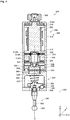
- the measuring probe 300 includes: a stylus 336 having a contact part 362 to be in contact with the object W to be measured; a probe housing 306 configured to be capable of supporting the stylus 336 on an axial center O; detection elements 325 configured to be capable of detecting movements of the contact part 362 deviating from the axial center O and on the axial center O; and a signal processing circuit 320 configured to process outputs of the detection elements 325 to output a digital touch signal CP.
- the measuring probe 300 is configured as a touch signal probe.
- the stylus 336 is included in a stylus module 304, and the probe housing 306 and the detection elements 325 are included in a probe main body 302.
- the probe main body 302 is supported by a spindle 224 of the drive mechanism 220.
- the stylus module 304 is detachably coupled to the probe main body 302 with high positional reproducibility via a kinematic joint (which will be described later).
- the measuring probe 300 will be described below in detail.
- the horizontal direction on the plane of paper in Fig. 2 is defined as an X-direction; the vertical direction to the plane of the paper is defined as a Y-direction; and the longitudinal direction on the plane of paper is defined as a Z-direction.
- the direction of the axial center O (axial direction O) in the measuring probe 300 coincides with the Z direction.
- the measuring probe 300 is identical with a probe unit 301 in the present embodiment.
- the probe main body 302 includes the probe housing 306, the signal processing circuit 320, supporting members 322 and 324, the detection elements 325, a coupling shaft 326, a flange member 328, a permanent magnet 330, and balls 332.
- the probe housing 306 includes an attachment part 308, a circuit placement part 310, a fixing member 314, a bottom member 316, and a main body cover 318.
- the attachment part 308 is a part to be attached to the spindle 224 at the upper end of the measuring probe 300.
- the attachment part 308 is provided with, for example, a head to be inserted into a fitting part provided in the spindle 224. Note that a cable and a connector for electrical connection may be used separately from the attachment part.
- the attachment part 308 serves also as one of connection terminals configured to be capable of electrically connecting to the motion controller 700.
- the circuit placement part 310 is disposed at a lower end of the attachment part 308.
- a cross-section of the circuit placement part 310 perpendicular to the axial center O has a generally triangular shape except for a disc-shaped upper end part 310A and a disc-shaped lower flange 312 provided at a lower end of the circuit placement part 310.
- the signal processing circuit 320 is disposed around the generally triangular shape.
- the circuit placement part 310 is disposed above the supporting members 322 and 324.
- the fixing member 314 is fixed to a lower end peripheral part 312B of the lower flange 312 with the supporting member 322 interposed therebetween.
- the fixing member 314 has a cylindrical shape provided with an opening 314A on the axial center O.
- a lower end inner surface of the fixing member 314 is provided with four depressed parts 314C with fourfold symmetry.
- the bottom member 316 is fixed to a lower end peripheral part of the fixing member 314 with the supporting member 324 interposed therebetween.
- the bottom member 316 has an annular shape.
- the main body cover 318 has a cylindrical shape and disposed around the circuit placement part 310, the lower flange 312, the fixing member 314 and the bottom member 316 in such a manner as to cover all of the signal processing circuit 320.
- the main body cover 318 is fixed to the fixing member 314 via bolts.
- the signal processing circuit 320 is a circuit configured to process outputs of the detection elements 325 to output the digital touch signal (contact sensing signal) CP for notifying that the contact part 362 is in contact with the object W to be measured.
- the signal processing circuit 320 is configured to obtain deflection amounts in the three X-, Y-, and Z-directions on the basis of outputs of the four detection elements 325, synthesize the deflection amounts in the three directions, and output the digital touch signal CP when the contact part 362 produces a given displacement or more. The specific configuration thereof will be described later.
- the supporting members 322 and 324 are elastically-deformable members disposed in the axial direction O of the probe housing 306 and allowing for orientation changes of the stylus 336.
- the supporting members 322 and 324 may be formed of, for example, a SUS(SST) material, but other materials may be employed.
- the supporting member 324 has a rotationally symmetric shape including a total of four deformable arm parts 324B at positions displaced from each other by an angle of 90 degrees in a circumferential direction (around the axial center O) as illustrated in Fig. 3 . These four arm parts 324B are formed on the same plane.
- the supporting members 322 and 324 have the same thickness and the same structure except for the widths of the respective arm parts 324B. Without being limited thereto, the thicknesses, lengths, and shapes of their arm parts 324B may be different from each other, or the entire supporting members 322 and 324 may have shapes different from each other. Thus, the supporting member 324 in which the detection elements 325 are disposed will be described below, and any overlapping description on the supporting member 322 will be omitted. Note that the structure of the supporting members is not limited to the shape shown in the present embodiment.
- the supporting member 324 has a generally circular plate shape, including, in addition to the rectangular arm parts 324B, a central part 324A connected to the coupling shaft 326, and a peripheral part 324C that is coupled to the central part 324A by the arm parts 324B and that is connected to the probe housing 306.
- the peripheral part 324C is at the outermost position of the supporting member 324, and the arm parts 324B are disposed on an inner side of the peripheral part 324C in such a manner as to extend linearly in a radial direction.
- the central part 324A is disposed on an inner side of the arm parts 324B.
- the supporting member 324 is configured so that a displacement of the coupling shaft 326 with respect to the probe housing 306 causes the central part 324A to move up, down, left, or right and thereby causes the arm parts 324B to be elastically deformed.
- the detection element 325 is, for example, a strain gauge to be affixed and detects a strain of the supporting member 324 in which the detection elements 325 are disposed as illustrated in FIG 3 .
- the detection elements 325 are disposed in the arm parts 324B of the supporting member 324 and fixed with an adhesive, for example.
- the coupling shaft 326 has a generally cylindrical shape, and is coupled to the two supporting members 322 and 324.
- the coupling shaft 326 is held on the axial center O by the two supporting members 322 and 324 without being in contact with the lower flange 312, the fixing member 314, and the bottom member 316.
- the coupling shaft 326 integrally supports the flange member 328.
- the flange member 328 has a generally disc shape.
- the flange member 328 faces the bottom member 316 in the axial direction O in a non-contact manner and faces the main body cover 318 in the radial direction in a non-contact manner.
- the flange member 328 supports the stylus module 304. At least a part of a gap between the bottom member 316 and the flange member 328 is filled with a viscous material such as a grease oil.
- the permanent magnet 330 is fixed, on the axial center O, to a lower surface of the flange member 328.
- the three balls 332 are disposed with rotational symmetry at an interval of 120 degrees in the circumferential direction in such a manner as to surround the permanent magnet 330 in a lower end outer region of the flange member 328.
- the stylus module 304 includes an over-travel mechanism 334, and the stylus 336 supported by the over-travel mechanism 334.
- the over-travel mechanism 334 is a mechanism that changes the position of the stylus 336 when a large force greater than a measuring force F in outputting the digital touch signal CP is applied to the stylus 336 and automatically restores the position of the stylus 336 when the large force disappears. That is, when such a large force is applied to the stylus 336, the over-travel mechanism 334 functions to change the position of the stylus 336 before the stylus module 304 comes off from the probe main body 302.
- the over-travel mechanism 334 includes a flange part 338, an extended part 344, a stylus holder 346, and a coil spring 350.
- the flange part 338 is a member corresponding to the flange member 328. That is, three V-grooves 340 are disposed at an interval of 120 degrees in the circumferential direction of the flange part 338 in such a manner as to be in contact with the balls 332.
- a magnetic member (a permanent magnet, for example) 342 attracted to the permanent magnet 330 is disposed in the flange part 338 in such a manner as to face the permanent magnet 330.
- each V-groove 340 is in contact with the surface of a corresponding one of the balls 332.
- the flange part 338 is seated on (in contact with) the flange member 328 at six points. That is, the flange member 328 and the flange part 338 can be coupled to each other while achieving high positioning accuracy.
- the flange part 338 and the flange member 328 constitute a kinematic joint, which is a detachable coupling mechanism. Such a kinematic joint allows for high positioning reproducibility even when the probe main body 302 and the stylus module 304 are repeatedly detached from, and attached to, each other.
- the extended part 344 is integrally formed with a periphery of the flange part 338 and houses the coil spring 350 expandable in the axial direction O.
- the stylus holder 346 is provided at an end of the extended part 344 in the axial direction O and connected to the extended part 344 via bolts.
- the stylus holder 346 movably supports, at its upper surface closer to the coil spring 350, a flange part 356 of the stylus 336 pressed by the coil spring 350.
- Three balls 348 are disposed on the upper surface of the stylus holder 346 closer to the coil spring 350 at an interval of 120 degrees in the circumferential direction.
- V-grooves 358 are provided on a lower surface of the flange part 356 at an interval of 120 degrees in the circumferential direction in such a manner as to correspond to the balls 348.
- the axial direction of the V-groove 358 is identical with a generally radial direction heading to the axial center O. That is, it can be said that the stylus holder 346 and the flange part 356 constitute the aforementioned kinematic joint.
- the over-travel mechanism 334 can achieve high positioning reproducibility of the stylus 336 with respect to the flange part 338 within the range of the measuring force F not exceeding the pressing force of the coil spring 350. If a large force greater than the predetermined spring force given by the coil spring 350 is applied to the stylus 336, the flange part 356 is off from the stylus holder 346, thus preventing the stylus module 304 from dropping off from the probe main body 302.
- the stylus 336 includes: the flange part 356 supported by the stylus holder 346 as described above; a rod part 360 configured to extend from the flange part 356 in the axial direction O; and the contact part 362 provided at the tip of the rod part 360.
- the base end of the rod part 360 is attached to the flange part 356.
- the spherical contact part 362 to be in contact with the object W to be measured is provided at the tip of the rod part 360, i.e., the stylus 336 has the contact part 362 to be in contact with the object W to be measured.
- the central axis direction of the stylus 336 coincides with the Z-direction (the axial direction O) when the stylus 336 has no displacement in the X-Y direction.
- the signal processing circuit 320 incudes a signal synthesizing portion 364, and a signal outputting portion 366.
- the signal synthesizing portion 364 processes the outputs of the detection elements 325 to output a composite signal Sc obtained by synthesizing displacement components of the contact part 362 in the three X-, Y-, and Z-directions perpendicular to one another.
- the signal outputting portion 366 outputs the digital touch signal CP to the outside of the measuring probe 300, i.e., the main body device 101 when the composite signal Sc satisfies a predetermined threshold condition (or a threshold condition).
- the signal outputting portion 366 includes: a condition storing portion 368 configured to store five predetermined threshold conditions (any plural number of threshold conditions may be stored); and three comparing portions 370 (a first comparing portion 370A, a second comparing portion 370B, and a third comparing portion 370C) each configured to compare a predetermined threshold condition with the composite signal Sc (any plural number of comparing portions may be employed).
- the signal outputting portion 366 outputs the digital touch signals CP corresponding to the outputs of at least two (the comparing portions 370A and 370B) of the three comparing portions 370.
- the digital touch signals CP in the present embodiment are an output CP1 of the first comparing portion 370A and an output CP2 of the second comparing portion 370B.
- the digital touch signal CP is an output CP3 of the third comparing portion 370C.
- the outputs of the first comparing portion 370A, the second comparing portion 370B, and the third comparing portion 370C are outputted as parallel digital data. Any one of the threshold conditions is set by default in each of the first comparing portion 370A, the second comparing portion 370B, and the third comparing portion 370C.
- the digital touch signal CP may be transmitted to the main body device 101 by wire via the attachment part 308, or may be transmitted to the main body device 101 by air.
- the condition storing portion 368 stores a plurality of other threshold conditions that can replace the threshold conditions set in the comparing portions 370 by default (i.e., the predetermined threshold conditions). For example, when the measuring probe 300 measures the object W to be measured, the condition storing portion 368 stores combinations of four signal levels SL1, SL2, SL3, and SL4 and three durations 0, T0 ( ⁇ 0), and T1 ( ⁇ 0, ⁇ T0) of the signal levels, i.e., a maximum of 12 threshold conditions (the sum of the threshold conditions set in the comparing portions 370 by default (the predetermined threshold conditions) and the other threshold conditions).
- the condition storing portion 368 stores combinations of a single signal level SL5 and three durations 0, T0 ( ⁇ 0), and T1 ( ⁇ 0, ⁇ T0) of the signal level, i.e., a maximum of three threshold conditions (the sum of the threshold condition set in the comparing portion 370 by default (the predetermined threshold condition) and the other threshold conditions).
- the condition storing portion 368 can store a plurality of threshold conditions.
- a predetermined threshold condition includes a signal level and a duration of the signal level. As illustrated in Fig.
- the thresholds set in these first comparing portion 370A, second comparing portion 370B, and third comparing portion 370C can be selected by a rewrite signal SS of the main body device 101. That is, the predetermined threshold conditions of the comparing portions 370 are replaced by the other threshold conditions by the rewrite signal SS outputted from the main body device 101. Note that the threshold conditions of the condition storing portion 368 can be rewritten by the main body device 101.
- Each of the comparing portions 370 compares the composite signal Sc, which is an output of the signal synthesizing portion 364, with a threshold condition set by the condition storing portion 368.
- three comparing portions 370 may be provided as hardware, all of the comparing portions 370 may be configured as software in a single FPGA.
- the main body device 101 represents the entire configuration of the measuring system 100 excluding the measuring probe 300. That is, the main body device 101 is configured to movably support the measuring probe 300 and obtain the shape of the object W to be measured on the basis of the outputs of the signal processing circuit 320. Note that only a part of the main body device 101 associated with the digital touch signals CP is illustrated in Fig. 3 .
- the main body device 101 includes a main body processing portion 102.
- the main body processing portion 102 corresponds to the functions of the motion controller 700 and the host computer 800 illustrated in Fig. 1 .
- the main body processing portion 102 receives the digital touch signals CP and obtains the shape of the object W to be measured when the outputs of the first comparing portion 370A and the second comparing portion 370B satisfy the threshold conditions different from each other. That is, when the digital touch signals CP1 and CP2 shown in Figs.
- the main body processing portion 102 can obtain the shape of the object W to be measured using a start time of the digital touch signal CP1 as a time at which the contact part 362 just comes into contact with the object W to be measured.
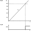
- comparing portions 370 when the measuring probe 300 measures the object W to be measured will be described next with reference to Figs. 4A, 4B, and 4C .
- the vertical axis represents a signal level SL
- the horizontal axis represents an elapsed time t (the same applies to Figs. 5A and 6A ).
- a threshold condition (the signal level SL1 and the signal level duration (the duration of the signal level) 0) is set in the first comparing portion 370A
- another threshold condition (the signal level SL2 and the signal level duration 0) is set in the second comparing portion 370B.
- the first comparing portion 370A outputs the digital touch signal CP1 shown in Fig. 4C
- the second comparing portion 370B outputs the digital touch signal CP2 shown in Fig. 4B .
- the third comparing portion 370C in the present embodiment is used when the measuring probe 300 is just moved without measuring the object W to be measured.
- the signal outputting portion 366 in this case outputs the digital touch signals CP1 and CP2 using the two threshold conditions having different signal levels SL1 and SL2 and having the same duration of these signal levels (e.g., the duration of the signal levels is 0).
- the signal level SL2 is significantly higher (e.g., severalfold) than the signal level SL1).
- the duration of the signal level SL2 is desirably greater than or equal to 0.
- the signal outputting portion 366 outputs the digital touch signals CP using two of the predetermined threshold conditions in which the signal levels SL1 and SL2 are different from each other and the duration of the signal level SL2 which has a higher level of the signal level is greater than or equal to the duration of the signal level SL1 which has a lower level of the signal level.
- the composite signal Sc shown in Fig. 5A is inputted to the comparing portions 370, a threshold condition (the signal level SL1 and the signal level duration 0) is set in the first comparing portion 370A, and another threshold condition (the signal level SL1 and the signal level duration T0) is set in the second comparing portion 370B.
- the first comparing portion 370A outputs the digital touch signal CP1 shown in Fig. 5C
- the second comparing portion 370B outputs the digital touch signal CP2 shown in Fig. 5B .
- the digital touch signal CP2 is outputted as a result of the composite signal Sc exceeding the signal level SL1 and lasting for the signal level duration T0 or more.
- the third comparing portion 370C is used when the measuring probe 300 is just moved without measuring the object W to be measured. That is, when the measuring probe 300 measures the object W to be measured, the signal outputting portion 366 in this case outputs the digital touch signals CP1 and CP2 using two of the predetermined threshold conditions in which the signal levels are the same (SL1) as each other and the durations of the signal levels are different from each other (0 and T0).
- the signal outputting portion 366 is configured to output the digital touch signal using the predetermined threshold condition having the signal level higher than the signal levels used when the measuring probe 300 measures the object W to be measured.
- the composite signal Sc shown in Fig. 6A is inputted to the comparing portions 370 when the measuring probe 300 is just moved without measuring the object W to be measured, and a threshold condition (the signal level SL5 and the signal level duration 0) is set in the third comparing portion 370C.
- the third comparing portion 370C then outputs the digital touch signal CP3 shown in Fig. 6B .
- the main body processing portion 102 outputs a command to cease the movement of the measuring probe 300 to the drive mechanism 220 rather than obtaining the shape of the object W to be measured.
- the signal processing circuit 320 in the present embodiment includes the signal synthesizing portion 364, and the signal outputting portion 366 configured to output the digital touch signals CP to the main body device 101 when the composite signal Sc satisfies the threshold conditions.
- the signal outputting portion 366 includes the three comparing portions 370 each configured to compare the composite signal Sc with the threshold conditions.
- the signal outputting portion 366 is configured to output the digital touch signals CP corresponding to the outputs of the first comparing portion 370A and the second comparing portion 370B. That is, the signal outputting portion 366 outputs the digital touch signals CP obtained under different threshold conditions.
- the measuring probe 300 Since signals outputted from the measuring probe 300 are the digital touch signals CP, the measuring probe 300 has high noise resistance. Moreover, since the digital touch signals CP are those obtained under the different threshold conditions, the accuracy of one of the digital touch signals CP can be verified by the other one of the digital touch signals CP. For example, whether the digital touch signal CP1 obtained under a high-sensitive threshold condition has been obtained as a result of the actual contact of the contact part 362 with the object W to be measured can be determined on the basis of the presence or absence of the digital touch signal CP2 obtained under a low-sensitive threshold condition. Furthermore, measurement accuracy, measurement stability, or measurement variation, for example, can also be estimated on the basis of the occurrence frequencies of those digital touch signals CP.
- the signal outputting portion 366 includes the condition storing portion 368 configured to store a plurality of other threshold conditions capable of replacing the predetermined threshold conditions set in the comparing portions 370 by default.
- the rewrite signal SS can be a simple signal that merely selects from the other threshold conditions stored in the condition storing portion 368. That is, the rewrite signal SS can be made simpler, and the threshold conditions can be set safely and reliably as compared to when the threshold conditions are externally rewritten in a direct manner.
- optimum threshold conditions can be selected by the rewrite signal SS while the measuring probe 300 is operated. Without being limited thereto, the threshold conditions can be selected after removing the measuring probe.
- the digital touch signals CP are outputted as parallel digital data. This can simplify the configuration of the circuit for outputting the digital touch signals CP as compared to when the digital touch signals CP are outputted as serial data. Thus, it is easy to ensure a lighter weight, a lower cost, and stable operations of the measuring probe 300. At the same time, since the digital touch signals CP are outputted as parallel digital data, the response speed of the measuring probe 300 to a measurement can be increased as compared to a case where the digital touch signals CP are outputted as serial digital data.
- the predetermined threshold condition includes the signal level and the duration of the signal level. Due to such inclusion of a temporal element, the accuracy of the digital touch signal CP can be ensured in a more multifaceted way as compared to a case where a threshold condition is selected on the basis of the signal level only. Without being limited thereto, the threshold condition may include only the signal level or only the duration of the signal level.
- the signal outputting portion 366 in the present embodiment can output the digital touch signals CP using two of the predetermined threshold conditions in which signal levels are different from each other and the duration of the signal level which has higher level of the signal level is greater than or equal to the duration of the signal level which has lower level of the signal level.
- the threshold conditions can be set more appropriately if a difference in the signal levels is a major factor in lowering measurement accuracy or the like.
- the signal outputting portion 366 in the present embodiment can output the digital touch signals CP using two of the predetermined threshold conditions in which the signal levels are the same as each other and the durations of the signal levels are different from each other.
- the threshold conditions can be set more appropriately if a difference in the durations of the signal levels is a major factor in lowering measurement accuracy or the like.
- the signal outputting portion 366 in the present embodiment outputs the digital touch signal CP using the predetermined threshold condition in which the signal level (the signal level SL5) is higher than those used when the measuring probe 300 measures the object W to be measured.
- the digital touch signal CP is outputted only in a case of an accidental collision, for example, during a movement of the measuring probe 300 without a measuring operation. This allows for a rapid movement of the measuring probe 300, and only the collision of the measuring probe 300 can be reliably detected.
- a plurality of the durations of the signal level can be set in this case.
- the digital touch signal CP can be prevented from being outputted erroneously due to disturbance vibrations while the measuring probe 300 is just moved.
- the measuring probe 300 and the measuring system 100 that can stably make measurements with high accuracy while keeping high noise resistance can be obtained according to the present embodiment.
- the digital touch signals CP are outputted as parallel digital data in the first embodiment, the present invention is not limited thereto.
- the digital touch signals CP may be configured as in a second embodiment illustrated in Fig. 7 , for example.
- the second embodiment differs from the first embodiment in that digital touch signals CP are converted into serial digital data and then outputted.
- a description on elements of the second embodiment will be omitted here except for the configuration of a converting portion 472 involved in the conversion of a signal outputting portion 466.
- their reference numerals in the second embodiment are basically the same as those of the first embodiment except for their first digit.
- a measuring probe 400 and a probe unit 401 are identical with each other.
- the signal outputting portion 466 in the second embodiment includes the converting portion 472 as a subsequent stage of comparing portions 470.
- the converting portion 472 sequentially transmits states (L level and/or H level) of digital touch signals CP1 and CP2 at a given time as a single data unit (serial data) at a constant frequency (e.g., several kHz).
- a constant frequency e.g., several kHz.
- the digital touch signal CP1 at the H level and the digital touch signal CP2 at the L level are transmitted as a single data unit at fixed time intervals.
- the digital touch signal CP1 at the H level and the digital touch signal CP2 at the H level are transmitted as a single data unit at fixed time intervals.
- the digital touch signal CP2 is changed to the H level while the digital touch signal CP1 is kept at the H level after the digital touch signal CP1 is changed from the L level to the H level (in a state where a threshold condition in a first comparing portion 470A is being satisfied continuously), those are determined as digital touch signals (trigger signals) produced as a result of the contact of the stylus 436 with the object W to be measured.
- a main body processing portion 104 can then obtain the shape of the object W to be measured using the time at which the initial digital touch signal CP1 is changed to the H level as a time at which the stylus 436 comes into contact with the object W to be measured.
- the digital touch signals CP are outputted as serial digital data in the present embodiment, the number of signal lines for the digital touch signals CP can be reduced in the measuring probe 400. This can simplify wiring in the attachment part, in particular.
- a measuring probe and a probe unit may be configured as those in a third embodiment illustrated in Fig. 8 .
- the third embodiment differs from the above-described embodiments in that a signal outputting portion 566 further includes a probe interface portion 574 connected to a measuring probe 500. That is, a part (the probe interface portion 574) of the signal outputting portion 566 is provided outside the measuring probe 500.
- a description on elements of the third embodiment will be omitted here except for configurations associated with the probe interface portion 574. Note that their reference numerals in the third embodiment are basically the same as those of the second embodiment except for their first digit.
- the probe interface portion 574 of the signal outputting portion 566 is connected to a main body device 105 in the third embodiment.
- signal levels of predetermined threshold conditions in a condition storing portion 568 are set in a first comparing portion 570A, a second comparing portion 570B, and a third comparing portion 570C, and the same signal level duration (i.e., 0) is set in the first comparing portion 570A, the second comparing portion 570B, and the third comparing portion 570C.
- the probe interface portion 574 is connected to the measuring probe 500 to determine if durations of outputs of the first comparing portion 570A, the second comparing portion 570B, and the third comparing portion 570C exceed the signal level durations of the predetermined threshold conditions that would have been otherwise set in the first comparing portion 570A, the second comparing portion 570B, and the third comparing portion 570C, respectively.
- the probe interface portion 574 is configured to output a digital touch signal CP when the durations of the outputs of the first comparing portion 570A, the second comparing portion 570B, and the third comparing portion 570C exceed those signal level durations of the predetermined threshold conditions.
- the probe interface portion 574 in the present embodiment performs processing on the signal level durations that would have been otherwise set in the first comparing portion 570A, the second comparing portion 570B, and the third comparing portion 570C and processed in the first comparing portion 570A, the second comparing portion 570B, and the third comparing portion 570C, respectively.
- This can simplify processing performed by the measuring probe 500 and can reduce the load of the measuring probe 500.
- the same signal level may be set in the first comparing portion 570A and the second comparing portion 570B. In this case, threshold conditions set in the first comparing portion 570A and the second comparing portion 570B are the same as each other.
- the probe interface portion 574 in the third embodiment performs the processing on the signal level durations that would have been otherwise processed in the first comparing portion 570A, the second comparing portion 570B, and the third comparing portion 570C, respectively
- the present invention is not limited thereto.
- Such processing may be performed as in a fourth embodiment illustrated in Fig. 9 , for example.
- the fourth embodiment differs from the third embodiment in that a measuring probe 600 and a probe unit 601 are identical with each other.
- the measuring probe 600 does not include condition storing portion.
- a description on elements of the fourth embodiment will be omitted here except for configurations different from those of the third embodiment. Note that their reference numerals in the fourth embodiment are basically the same as those of the third embodiment except for their first digit.
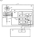
- a main body processing portion 108 performs the processing, which has been performed by the probe interface portion 574 in the third embodiment. That is, the main body processing portion 108 is connected to the measuring probe 600 to determine if durations of outputs of a first comparing portion 670A, a second comparing portion 670B, and a third comparing portion 670C exceed signal level durations of predetermined threshold conditions that would have been otherwise set in the first comparing portion 670A, the second comparing portion 670B, and the third comparing portion 670C, respectively.
- the main body processing portion 108 configures a digital touch signal CP when the durations of the outputs of the first comparing portion 670A, the second comparing portion 670B, and the third comparing portion 670C exceed those signal level durations of the predetermined threshold conditions.
- the configured digital touch signal CP is further processed in the main body processing portion 108.
- a signal processing circuit 620 in the present embodiment includes: a signal synthesizing portion 664; and a signal outputting portion 666 configured to output digital touch signals CP1, CP2, and CP3 to a main body device 107 when a composite signal Sc satisfies parts of the predetermined threshold conditions.
- the signal outputting portion 666 includes the three comparing portions 670A, 670B, and 670C each configured to compare a part (signal level) of the predetermined threshold condition with the composite signal Sc.
- the signal outputting portion 666 outputs the digital touch signals CP1 and CP2 corresponding to the outputs of the first comparing portion 670A and the second comparing portion 670B.
- Each of the predetermined threshold condition includes the signal level and the duration of the signal level. The signal level of each of the predetermined threshold conditions is applied in the first comparing portion 670A and the second comparing portion 670B, and the durations of the signal levels are the same (e.g., 0).
- the main body device 107 is configured to apply the signal level durations of the predetermined threshold conditions to the digital touch signals CP1 and CP2 upon the reception of the digital touch signals CP1 and CP2 and obtain the shape of the object W to be measured when the outputs of the first comparing portion 670A and the second comparing portion 670B satisfy the predetermined threshold conditions.
- the measuring probe 600 in the present embodiment does not include condition storing portion. More specifically, the thresholds conditions in the comparing portions 670 are directly rewritten by a rewrite signal SS.
- the rewrite signal SS in this case may be a signal representing a threshold condition prestored outside the measuring probe 600, or a signal of a threshold condition created on the spot.
- the present invention is not limited thereto. It is only necessary that two or more comparing portions be provided. For example, four or more comparing portions may be provided. For example, a plurality of comparing portions corresponding to the number of conceivable predetermined threshold conditions that is greater than the number of actually-used comparing portions may be provided, and all of their digital touch signals may be inputted to the main body processing portion.
- the main body processing portion may be configured to be able to select which outputs of the comparing portions are to be processed. Such a configuration can eliminate the need for the rewrite signal from the main body processing portion, and can simplify control inside the measuring probe.
- the present invention can be widely applied to probe units and measuring systems that are used for measuring three-dimensional shapes of objects to be measured.
Landscapes
- Physics & Mathematics (AREA)
- General Physics & Mathematics (AREA)
- Length Measuring Devices With Unspecified Measuring Means (AREA)
- A Measuring Device Byusing Mechanical Method (AREA)
Abstract
Description
- Japanese Patent Applications No.
2018-222917 filed on November 28, 2018 - 0001 The present invention relates to a probe unit and a measuring system, and in particular, to a probe unit and a measuring system that can stably make measurements with high accuracy while keeping high noise resistance.
- 0002 A measuring probe as described in Japanese Patent No.
6212148 - 0003 In the measuring probe described in Japanese Patent No.
6212148 6212148 - 0004 The present invention has been made in order to solve the above-described problems in the conventional technique, and an object thereof is to provide a probe unit and a measuring system that can stably make measurements with high accuracy while keeping high noise resistance.
- 0005 To solve the above-described problems, a first aspect of the present invention provides a probe unit having a measuring probe including: a stylus having a contact part to be in contact with an object to be measured; a detection element configured to be capable of detecting a movement of the contact part; and at least part of a signal processing circuit configured to process an output of the detection element to output a digital touch signal. The signal processing circuit includes: a signal synthesizing portion configured to process the output of the detection element to output a composite signal obtained by synthesizing displacement components of the contact part in three directions perpendicular to one another; and a signal outputting portion configured to output the digital touch signal to the outside of the probe unit when the composite signal satisfies a predetermined threshold condition. The signal outputting portion includes a plurality of comparing portions each configured to compare at least a part of the predetermined threshold condition with the composite signal. When the measuring probe measures the object to be measured, the signal outputting portion outputs the digital touch signal corresponding to outputs of two or more comparing portions of the plurality of comparing portions.
- 0006 A second aspect of the present invention provides the probe unit in which the signal outputting portion further includes a condition storing portion configured to store a plurality of other threshold conditions capable of replacing the predetermined threshold condition set in the comparing portion by default.
- 0007 A third aspect of the present invention provides the probe unit in which the digital touch signal is outputted as parallel digital data.
- 0008 A fourth aspect of the present invention provides the probe unit in which the digital touch signal is outputted as serial digital data.
- 0009 A fifth aspect of the present invention provides the probe unit in which the predetermined threshold condition includes a signal level and a duration of the signal level.
- 0010 A sixth aspect of the present invention provides the probe unit in which the signal level of the predetermined threshold condition is set in each of the two or more comparing portions, and the durations of the signal levels are set to be the same as each other in the two or more comparing portions. The signal outputting portion further includes a probe interface portion which is connected to the measuring probe and configured to determine if durations of the outputs of the two or more comparing portions exceed the durations of the signal levels of the predetermined threshold conditions, respectively, and to output the digital touch signal when the durations of the outputs of the two or more comparing portions exceed the durations of the signal levels of the predetermined threshold conditions.
- 0011 A seventh aspect of the present invention provides the probe unit in which, when the measuring probe measures the object to be measured, the signal outputting portion outputs the digital touch signal using two of the predetermined threshold conditions in which the signal levels are different from each other and the duration of the signal level which has a higher level of the signal level is greater than or equal to the duration of the signal level which has a lower level of the signal level.
- 0012 An eighth aspect of the present invention provides the probe unit in which, when the measuring probe measures the object to be measured, the signal outputting portion outputs the digital touch signal using two of the predetermined threshold conditions in which the signal levels are the same as each other and the durations of the signal levels are different from each other.
- 0013 A ninth aspect of the present invention provides the probe unit in which, when the measuring probe is just moved without measuring the object to be measured, the signal outputting portion outputs the digital touch signal using the predetermined threshold condition having the signal level higher than the signal levels used when the measuring probe measures the object to be measured.
- 0014 A tenth aspect of the present invention provides a measuring system including: a measuring probe including a stylus having a contact part to be in contact with an object to be measured, a detection element configured to be capable of detecting a movement of the contact part, and a signal processing circuit configured to process an output of the detection element to output a digital touch signal; and a main body device configured to movably support the measuring probe and obtain a shape of the object to be measured on the basis of an output of the signal processing circuit. The signal processing circuit includes: a signal synthesizing portion configured to process the output of the detection element to output a composite signal obtained by synthesizing displacement components of the contact part in three directions perpendicular to one another; and a signal outputting portion configured to output the digital touch signal to the main body device when the composite signal satisfies a predetermined threshold condition. The signal outputting portion includes a plurality of comparing portions each configured to compare the predetermined threshold condition with the composite signal. When the measuring probe measures the object to be measured, the signal outputting portion outputs the digital touch signal corresponding to outputs of two or more comparing portions of the plurality of comparing portions. The main body device receives the digital touch signal and obtains the shape of the object to be measured when the outputs of the two or more comparing portions satisfy the predetermined threshold condition.
- 0015 An eleventh aspect of the present invention provides a measuring system including: a measuring probe including a stylus having a contact part to be in contact with an object to be measured, a detection element configured to be capable of detecting a movement of the contact part, and a signal processing circuit configured to process an output of the detection element to output a digital touch signal; and a main body device configured to movably support the measuring probe and obtain a shape of the object to be measured on the basis of an output of the signal processing circuit. The signal processing circuit includes: a signal synthesizing portion configured to process the output of the detection element to output a composite signal obtained by synthesizing displacement components of the contact part in three directions perpendicular to one another; and a signal outputting portion configured to output the digital touch signal to the main body device when the composite signal satisfies a part of a predetermined threshold condition. The signal outputting portion includes a plurality of comparing portions each configured to compare the part of the predetermined threshold condition with the composite signal. When the measuring probe measures the object to be measured, the signal outputting portion outputs the digital touch signal corresponding to outputs of two or more comparing portions of the plurality of comparing portions. The predetermined threshold condition includes a signal level and a duration of the signal level. The signal level of the predetermined threshold condition is applied in the comparing portion, and the duration of the signal level is the same in all of the comparing portions. The main body device applies the duration of the signal level of the predetermined threshold condition to the digital touch signal upon the reception of the digital touch signal, and obtains the shape of the object to be measured when the outputs of the two or more comparing portions satisfy the predetermined threshold condition.
- 0016 A twelfth aspect of the present invention provides the measuring system in which the predetermined threshold condition can be replaced by another threshold condition by a rewrite signal outputted from the main body device.
- 0017 According to the present invention, it is possible to provide the measuring probe and the measuring system capable of stably making measurements with high accuracy while keeping high noise resistance.
- These and other novel features and advantages of the present invention will become apparent from the following detailed description of preferred embodiments.
- 0018 The preferred embodiments will be described with reference to the drawings, wherein like elements have been denoted throughout the figures with like reference numerals, and wherein:
-
Fig. 1 is a schematic diagram illustrating an example of a measuring system using a measuring probe according to a first embodiment of the present invention; -
Fig. 2 is a schematic diagram illustrating a cross-section of the measuring probe ofFig. 1 ; -
Fig. 3 is a block diagram illustrating a configuration of parts of the measuring probe ofFig. 2 and a main body device; -
Fig. 4A is a graph showing a relationship between a composite signal inputted to comparing portions ofFig. 3 at the time of measurement and two threshold conditions having different signal levels; -
Fig. 4B is a graph showing a digital touch signal obtained in a second comparing portion ofFig. 3 ; -
Fig. 4C is a graph showing a digital touch signal obtained in a first comparing portion ofFig. 3 ; -
Fig. 5A is a graph showing a relationship between a composite signal inputted to the comparing portions ofFig. 3 at the time of measurement and two threshold conditions having different durations; -
Fig. 5B is a graph showing a digital touch signal obtained in the second comparing portion ofFig. 3 ; -
Fig. 5C is a graph showing a digital touch signal obtained in the first comparing portion ofFig. 3 ; -
Fig. 6A is a graph showing a relationship between a composite signal inputted to the comparing portions ofFig. 3 at the time of movement and a threshold condition; -
Fig. 6B is a graph showing a digital touch signal obtained in a third comparing portion ofFig. 3 ; -
Fig. 7 is a block diagram illustrating a configuration of parts of a measuring probe and a main body device according to a second embodiment of the present invention; -
Fig. 8 is a block diagram illustrating a configuration of parts of a measuring probe and a main body device according to a third embodiment of the present invention; and -
Fig. 9 is a block diagram illustrating a configuration of parts of a measuring probe and a main body device according to a fourth embodiment of the present invention. - 0019 An example of an embodiment of the present invention will be described below in detail with reference to the drawings.
- 0020 A measuring system according to a first embodiment of the present invention will be described with reference to
Figs. 1 to 6B . - 0021 An overall configuration of a
measuring system 100 will be described first. - 0022 As illustrated in
Fig. 1 , themeasuring system 100 includes: acoordinate measuring machine 200 configured to move ameasuring probe 300; anoperation portion 110 having manually-operatedjoysticks 111; and amotion controller 700 configured to control operations of thecoordinate measuring machine 200. Themeasuring system 100 also includes: ahost computer 800 configured to operate thecoordinate measuring machine 200 via themotion controller 700 and process measured data acquired by thecoordinate measuring machine 200 to obtain, for example, dimensions or a shape of an object W to be measured; aninput unit 120 configured to input measurement conditions and the like; and anoutput unit 130 configured to output measurement results and the like. - 0023 As illustrated in
Fig. 1 , the coordinate measuringmachine 200 in the present embodiment includes: the measuringprobe 300; asurface plate 210; adrive mechanism 220 which is provided to stand on thesurface plate 210 and configured to move the measuringprobe 300 three-dimensionally; and a drive sensor (not illustrated) configured to detect a drive amount of thedrive mechanism 220. Note that a part of themeasuring system 100 excluding the measuringprobe 300 is referred to also as amain body device 101. - 0024 A general configuration of the measuring
probe 300 will next be described. - 0025 As illustrated in
Fig. 2 , the measuringprobe 300 includes: astylus 336 having acontact part 362 to be in contact with the object W to be measured; aprobe housing 306 configured to be capable of supporting thestylus 336 on an axial center O;detection elements 325 configured to be capable of detecting movements of thecontact part 362 deviating from the axial center O and on the axial center O; and asignal processing circuit 320 configured to process outputs of thedetection elements 325 to output a digital touch signal CP. Specifically, the measuringprobe 300 is configured as a touch signal probe. Note that thestylus 336 is included in astylus module 304, and theprobe housing 306 and thedetection elements 325 are included in a probemain body 302. The probemain body 302 is supported by aspindle 224 of thedrive mechanism 220. Thestylus module 304 is detachably coupled to the probemain body 302 with high positional reproducibility via a kinematic joint (which will be described later). - 0026 The measuring
probe 300 will be described below in detail. For the purpose of the following description, the horizontal direction on the plane of paper inFig. 2 is defined as an X-direction; the vertical direction to the plane of the paper is defined as a Y-direction; and the longitudinal direction on the plane of paper is defined as a Z-direction. Thus, the direction of the axial center O (axial direction O) in the measuringprobe 300 coincides with the Z direction. Note that the measuringprobe 300 is identical with aprobe unit 301 in the present embodiment. - 0027 As illustrated in
Fig. 2 , the probemain body 302 includes theprobe housing 306, thesignal processing circuit 320, supportingmembers detection elements 325, acoupling shaft 326, aflange member 328, apermanent magnet 330, andballs 332. - 0028 As illustrated in
Fig. 2 , theprobe housing 306 includes anattachment part 308, acircuit placement part 310, a fixingmember 314, abottom member 316, and amain body cover 318. - 0029 As illustrated in
Fig. 2 , theattachment part 308 is a part to be attached to thespindle 224 at the upper end of the measuringprobe 300. Theattachment part 308 is provided with, for example, a head to be inserted into a fitting part provided in thespindle 224. Note that a cable and a connector for electrical connection may be used separately from the attachment part. Theattachment part 308 serves also as one of connection terminals configured to be capable of electrically connecting to themotion controller 700. Thecircuit placement part 310 is disposed at a lower end of theattachment part 308. A cross-section of thecircuit placement part 310 perpendicular to the axial center O has a generally triangular shape except for a disc-shapedupper end part 310A and a disc-shapedlower flange 312 provided at a lower end of thecircuit placement part 310. Thesignal processing circuit 320 is disposed around the generally triangular shape. Thecircuit placement part 310 is disposed above the supportingmembers - 0030 As illustrated in
Fig. 2 , the fixingmember 314 is fixed to a lower endperipheral part 312B of thelower flange 312 with the supportingmember 322 interposed therebetween. The fixingmember 314 has a cylindrical shape provided with anopening 314A on the axial center O. A lower end inner surface of the fixingmember 314 is provided with fourdepressed parts 314C with fourfold symmetry. Thebottom member 316 is fixed to a lower end peripheral part of the fixingmember 314 with the supportingmember 324 interposed therebetween. Thebottom member 316 has an annular shape. Themain body cover 318 has a cylindrical shape and disposed around thecircuit placement part 310, thelower flange 312, the fixingmember 314 and thebottom member 316 in such a manner as to cover all of thesignal processing circuit 320. Themain body cover 318 is fixed to the fixingmember 314 via bolts. - 0031 As illustrated in
Fig. 3 , thesignal processing circuit 320 is a circuit configured to process outputs of thedetection elements 325 to output the digital touch signal (contact sensing signal) CP for notifying that thecontact part 362 is in contact with the object W to be measured. In brief, thesignal processing circuit 320 is configured to obtain deflection amounts in the three X-, Y-, and Z-directions on the basis of outputs of the fourdetection elements 325, synthesize the deflection amounts in the three directions, and output the digital touch signal CP when thecontact part 362 produces a given displacement or more. The specific configuration thereof will be described later. - 0032 As illustrated in
Fig. 2 , the supportingmembers probe housing 306 and allowing for orientation changes of thestylus 336. The supportingmembers member 324 has a rotationally symmetric shape including a total of fourdeformable arm parts 324B at positions displaced from each other by an angle of 90 degrees in a circumferential direction (around the axial center O) as illustrated inFig. 3 . These fourarm parts 324B are formed on the same plane. The supportingmembers respective arm parts 324B. Without being limited thereto, the thicknesses, lengths, and shapes of theirarm parts 324B may be different from each other, or the entire supportingmembers member 324 in which thedetection elements 325 are disposed will be described below, and any overlapping description on the supportingmember 322 will be omitted. Note that the structure of the supporting members is not limited to the shape shown in the present embodiment. - 0033 As illustrated in
Fig. 3 , the supportingmember 324 has a generally circular plate shape, including, in addition to therectangular arm parts 324B, acentral part 324A connected to thecoupling shaft 326, and a peripheral part 324C that is coupled to thecentral part 324A by thearm parts 324B and that is connected to theprobe housing 306. The peripheral part 324C is at the outermost position of the supportingmember 324, and thearm parts 324B are disposed on an inner side of the peripheral part 324C in such a manner as to extend linearly in a radial direction. Thecentral part 324A is disposed on an inner side of thearm parts 324B. The supportingmember 324 is configured so that a displacement of thecoupling shaft 326 with respect to theprobe housing 306 causes thecentral part 324A to move up, down, left, or right and thereby causes thearm parts 324B to be elastically deformed. - 0034 The
detection element 325 is, for example, a strain gauge to be affixed and detects a strain of the supportingmember 324 in which thedetection elements 325 are disposed as illustrated inFIG 3 . Thedetection elements 325 are disposed in thearm parts 324B of the supportingmember 324 and fixed with an adhesive, for example. - 0035 As illustrated in
Figs. 2 and3 , thecoupling shaft 326 has a generally cylindrical shape, and is coupled to the two supportingmembers coupling shaft 326 is held on the axial center O by the two supportingmembers lower flange 312, the fixingmember 314, and thebottom member 316. Thecoupling shaft 326 integrally supports theflange member 328. - 0036 As illustrated in
Fig. 2 , theflange member 328 has a generally disc shape. Theflange member 328 faces thebottom member 316 in the axial direction O in a non-contact manner and faces themain body cover 318 in the radial direction in a non-contact manner. Theflange member 328 supports thestylus module 304. At least a part of a gap between thebottom member 316 and theflange member 328 is filled with a viscous material such as a grease oil. This enables at least the viscous material to damp a displacement of theflange member 328 with respect to thebottom member 316, thereby reducing the occurrence of unwanted vibrations in an X-Y direction and the Z direction, which result from a movement of the measuringprobe 300, and preventing an increase in noise, which is accompanied by an increase in the sensitivity of the measuringprobe 300. Thepermanent magnet 330 is fixed, on the axial center O, to a lower surface of theflange member 328. The threeballs 332 are disposed with rotational symmetry at an interval of 120 degrees in the circumferential direction in such a manner as to surround thepermanent magnet 330 in a lower end outer region of theflange member 328. - 0037 As illustrated in
Fig. 2 , thestylus module 304 includes anover-travel mechanism 334, and thestylus 336 supported by theover-travel mechanism 334. - 0038 As illustrated in
Fig. 2 , theover-travel mechanism 334 is a mechanism that changes the position of thestylus 336 when a large force greater than a measuring force F in outputting the digital touch signal CP is applied to thestylus 336 and automatically restores the position of thestylus 336 when the large force disappears. That is, when such a large force is applied to thestylus 336, theover-travel mechanism 334 functions to change the position of thestylus 336 before thestylus module 304 comes off from the probemain body 302. Specifically, theover-travel mechanism 334 includes aflange part 338, anextended part 344, astylus holder 346, and acoil spring 350. - 0039 As illustrated in
Fig. 2 , theflange part 338 is a member corresponding to theflange member 328. That is, three V-grooves 340 are disposed at an interval of 120 degrees in the circumferential direction of theflange part 338 in such a manner as to be in contact with theballs 332. A magnetic member (a permanent magnet, for example) 342 attracted to thepermanent magnet 330 is disposed in theflange part 338 in such a manner as to face thepermanent magnet 330. - 0040 As illustrated in
Fig. 2 , each V-groove 340 is in contact with the surface of a corresponding one of theballs 332. Thus, when thepermanent magnet 330 and themagnetic member 342 are attracted to each other with a predetermined magnetic force, theflange part 338 is seated on (in contact with) theflange member 328 at six points. That is, theflange member 328 and theflange part 338 can be coupled to each other while achieving high positioning accuracy. More specifically, theflange part 338 and theflange member 328 constitute a kinematic joint, which is a detachable coupling mechanism. Such a kinematic joint allows for high positioning reproducibility even when the probemain body 302 and thestylus module 304 are repeatedly detached from, and attached to, each other. - 0041 As illustrated in
Fig. 2 , theextended part 344 is integrally formed with a periphery of theflange part 338 and houses thecoil spring 350 expandable in the axial direction O. Thestylus holder 346 is provided at an end of theextended part 344 in the axial direction O and connected to theextended part 344 via bolts. Thestylus holder 346 movably supports, at its upper surface closer to thecoil spring 350, aflange part 356 of thestylus 336 pressed by thecoil spring 350. Threeballs 348 are disposed on the upper surface of thestylus holder 346 closer to thecoil spring 350 at an interval of 120 degrees in the circumferential direction. Three V-grooves 358 are provided on a lower surface of theflange part 356 at an interval of 120 degrees in the circumferential direction in such a manner as to correspond to theballs 348. Note that the axial direction of the V-groove 358 is identical with a generally radial direction heading to the axial center O. That is, it can be said that thestylus holder 346 and theflange part 356 constitute the aforementioned kinematic joint. - 0042 Thus, when the
flange part 356 is being pressed by thecoil spring 350 with a predetermined spring force, theflange part 356 is seated on (in contact with) thestylus holder 346 at six points, thus being positioned at a fixed position. That is, theover-travel mechanism 334 can achieve high positioning reproducibility of thestylus 336 with respect to theflange part 338 within the range of the measuring force F not exceeding the pressing force of thecoil spring 350. If a large force greater than the predetermined spring force given by thecoil spring 350 is applied to thestylus 336, theflange part 356 is off from thestylus holder 346, thus preventing thestylus module 304 from dropping off from the probemain body 302. - 0043 As illustrated in
Fig. 2 , thestylus 336 includes: theflange part 356 supported by thestylus holder 346 as described above; arod part 360 configured to extend from theflange part 356 in the axial direction O; and thecontact part 362 provided at the tip of therod part 360. - 0044 As illustrated in
Fig. 2 , the base end of therod part 360 is attached to theflange part 356. Thespherical contact part 362 to be in contact with the object W to be measured is provided at the tip of therod part 360, i.e., thestylus 336 has thecontact part 362 to be in contact with the object W to be measured. Note that the central axis direction of thestylus 336 coincides with the Z-direction (the axial direction O) when thestylus 336 has no displacement in the X-Y direction. - 0045 The
signal processing circuit 320 and a part of themain body device 101 will be described next mainly with reference toFigs. 3 to 6B . - 0046 As illustrated in
Fig. 3 , thesignal processing circuit 320 incudes asignal synthesizing portion 364, and asignal outputting portion 366. - 0047 As illustrated in
Fig. 3 , thesignal synthesizing portion 364 processes the outputs of thedetection elements 325 to output a composite signal Sc obtained by synthesizing displacement components of thecontact part 362 in the three X-, Y-, and Z-directions perpendicular to one another. - 0048 As illustrated in
Fig. 3 , thesignal outputting portion 366 outputs the digital touch signal CP to the outside of the measuringprobe 300, i.e., themain body device 101 when the composite signal Sc satisfies a predetermined threshold condition (or a threshold condition). Specifically, thesignal outputting portion 366, as illustrated inFig. 3 , includes: acondition storing portion 368 configured to store five predetermined threshold conditions (any plural number of threshold conditions may be stored); and three comparing portions 370 (a first comparingportion 370A, a second comparingportion 370B, and a third comparing portion 370C) each configured to compare a predetermined threshold condition with the composite signal Sc (any plural number of comparing portions may be employed). When the measuringprobe 300 measures the object W to be measured, thesignal outputting portion 366 outputs the digital touch signals CP corresponding to the outputs of at least two (the comparingportions portions 370. When the measuringprobe 300 measures the object W to be measured, the digital touch signals CP in the present embodiment are an output CP1 of the first comparingportion 370A and an output CP2 of the second comparingportion 370B. When the measuringprobe 300 is just moved without measuring the object W to be measured, the digital touch signal CP is an output CP3 of the third comparing portion 370C. That is, for the digital touch signals CP, the outputs of the first comparingportion 370A, the second comparingportion 370B, and the third comparing portion 370C are outputted as parallel digital data. Any one of the threshold conditions is set by default in each of the first comparingportion 370A, the second comparingportion 370B, and the third comparing portion 370C. The digital touch signal CP may be transmitted to themain body device 101 by wire via theattachment part 308, or may be transmitted to themain body device 101 by air. - 0049 The
condition storing portion 368 stores a plurality of other threshold conditions that can replace the threshold conditions set in the comparingportions 370 by default (i.e., the predetermined threshold conditions). For example, when the measuringprobe 300 measures the object W to be measured, thecondition storing portion 368 stores combinations of four signal levels SL1, SL2, SL3, and SL4 and three durations 0, T0 (≠ 0), and T1 (≠ 0, ≠ T0) of the signal levels, i.e., a maximum of 12 threshold conditions (the sum of the threshold conditions set in the comparingportions 370 by default (the predetermined threshold conditions) and the other threshold conditions). When the measuringprobe 300 is just moved without measuring the object W to be measured, for example, thecondition storing portion 368 stores combinations of a single signal level SL5 and three durations 0, T0 (≠ 0), and T1 (≠ 0, ≠ T0) of the signal level, i.e., a maximum of three threshold conditions (the sum of the threshold condition set in the comparingportion 370 by default (the predetermined threshold condition) and the other threshold conditions). Without being limited thereto, thecondition storing portion 368 can store a plurality of threshold conditions. Here, a predetermined threshold condition includes a signal level and a duration of the signal level. As illustrated inFig. 3 , the thresholds set in these first comparingportion 370A, second comparingportion 370B, and third comparing portion 370C can be selected by a rewrite signal SS of themain body device 101. That is, the predetermined threshold conditions of the comparingportions 370 are replaced by the other threshold conditions by the rewrite signal SS outputted from themain body device 101. Note that the threshold conditions of thecondition storing portion 368 can be rewritten by themain body device 101. - 0050 Each of the comparing
portions 370 compares the composite signal Sc, which is an output of thesignal synthesizing portion 364, with a threshold condition set by thecondition storing portion 368. When the composite signal Sc satisfies the threshold condition, the comparingportion 370 outputs an H level (= 1). Otherwise, the comparingportion 370 outputs an L level (= 0). That is, when the composite signal Sc satisfies the threshold condition, the digital touch signal CP is continuously at the H level. Without being limited thereto, a pulsed digital touch signal CP may be continually outputted when the composite signal Sc satisfies the threshold condition. Although three comparingportions 370 may be provided as hardware, all of the comparingportions 370 may be configured as software in a single FPGA. - 0051 As illustrated in
Fig. 3 , themain body device 101 represents the entire configuration of themeasuring system 100 excluding the measuringprobe 300. That is, themain body device 101 is configured to movably support the measuringprobe 300 and obtain the shape of the object W to be measured on the basis of the outputs of thesignal processing circuit 320. Note that only a part of themain body device 101 associated with the digital touch signals CP is illustrated inFig. 3 . - 0052 As illustrated in
Fig. 3 , themain body device 101 includes a mainbody processing portion 102. The mainbody processing portion 102 corresponds to the functions of themotion controller 700 and thehost computer 800 illustrated inFig. 1 . The mainbody processing portion 102 receives the digital touch signals CP and obtains the shape of the object W to be measured when the outputs of the first comparingportion 370A and the second comparingportion 370B satisfy the threshold conditions different from each other. That is, when the digital touch signals CP1 and CP2 shown inFigs. 4B, 4C ,5B, and 5C are both at the H level, the mainbody processing portion 102 can obtain the shape of the object W to be measured using a start time of the digital touch signal CP1 as a time at which thecontact part 362 just comes into contact with the object W to be measured. - 0053 The operations of the comparing
portions 370 when the measuringprobe 300 measures the object W to be measured will be described next with reference toFigs. 4A, 4B, and 4C . InFig. 4A , the vertical axis represents a signal level SL, and the horizontal axis represents an elapsed time t (the same applies toFigs. 5A and6A ). For example, it is assumed that the composite signal Sc shown inFig. 4A is inputted to the comparingportions 370, a threshold condition (the signal level SL1 and the signal level duration (the duration of the signal level) 0) is set in the first comparingportion 370A, and another threshold condition (the signal level SL2 and the signal level duration 0) is set in the second comparingportion 370B. In this case, the first comparingportion 370A outputs the digital touch signal CP1 shown inFig. 4C , and the second comparingportion 370B outputs the digital touch signal CP2 shown inFig. 4B . Note that the third comparing portion 370C in the present embodiment is used when the measuringprobe 300 is just moved without measuring the object W to be measured. That is, when the measuringprobe 300 measures the object W to be measured, thesignal outputting portion 366 in this case outputs the digital touch signals CP1 and CP2 using the two threshold conditions having different signal levels SL1 and SL2 and having the same duration of these signal levels (e.g., the duration of the signal levels is 0). In reality, such a case occurs when the signal level SL2 is significantly higher (e.g., severalfold) than the signal level SL1). Unless the signal level SL2 greatly differs from the signal level SL1 (twofold or less), the duration of the signal level SL2 is desirably greater than or equal to 0. That is, when the measuringprobe 300 measures the object W to be measured, thesignal outputting portion 366 outputs the digital touch signals CP using two of the predetermined threshold conditions in which the signal levels SL1 and SL2 are different from each other and the duration of the signal level SL2 which has a higher level of the signal level is greater than or equal to the duration of the signal level SL1 which has a lower level of the signal level. - 0054 Alternatively, it is assumed that the composite signal Sc shown in
Fig. 5A is inputted to the comparingportions 370, a threshold condition (the signal level SL1 and the signal level duration 0) is set in the first comparingportion 370A, and another threshold condition (the signal level SL1 and the signal level duration T0) is set in the second comparingportion 370B. In this case, the first comparingportion 370A outputs the digital touch signal CP1 shown inFig. 5C , and the second comparingportion 370B outputs the digital touch signal CP2 shown inFig. 5B . The digital touch signal CP2 is outputted as a result of the composite signal Sc exceeding the signal level SL1 and lasting for the signal level duration T0 or more. Also in the present embodiment, the third comparing portion 370C is used when the measuringprobe 300 is just moved without measuring the object W to be measured. That is, when the measuringprobe 300 measures the object W to be measured, thesignal outputting portion 366 in this case outputs the digital touch signals CP1 and CP2 using two of the predetermined threshold conditions in which the signal levels are the same (SL1) as each other and the durations of the signal levels are different from each other (0 and T0). - 0055 When the measuring
probe 300 is just moved without measuring the object W to be measured, thesignal outputting portion 366 is configured to output the digital touch signal using the predetermined threshold condition having the signal level higher than the signal levels used when the measuringprobe 300 measures the object W to be measured. For example, it is assumed that the composite signal Sc shown inFig. 6A is inputted to the comparingportions 370 when the measuringprobe 300 is just moved without measuring the object W to be measured, and a threshold condition (the signal level SL5 and the signal level duration 0) is set in the third comparing portion 370C. The third comparing portion 370C then outputs the digital touch signal CP3 shown inFig. 6B . In this case, the mainbody processing portion 102 outputs a command to cease the movement of the measuringprobe 300 to thedrive mechanism 220 rather than obtaining the shape of the object W to be measured. - 0056 As described above, the
signal processing circuit 320 in the present embodiment includes thesignal synthesizing portion 364, and thesignal outputting portion 366 configured to output the digital touch signals CP to themain body device 101 when the composite signal Sc satisfies the threshold conditions. Thesignal outputting portion 366 includes the three comparingportions 370 each configured to compare the composite signal Sc with the threshold conditions. When the measuringprobe 300 measures the object W to be measured, thesignal outputting portion 366 is configured to output the digital touch signals CP corresponding to the outputs of the first comparingportion 370A and the second comparingportion 370B. That is, thesignal outputting portion 366 outputs the digital touch signals CP obtained under different threshold conditions. Since signals outputted from the measuringprobe 300 are the digital touch signals CP, the measuringprobe 300 has high noise resistance. Moreover, since the digital touch signals CP are those obtained under the different threshold conditions, the accuracy of one of the digital touch signals CP can be verified by the other one of the digital touch signals CP. For example, whether the digital touch signal CP1 obtained under a high-sensitive threshold condition has been obtained as a result of the actual contact of thecontact part 362 with the object W to be measured can be determined on the basis of the presence or absence of the digital touch signal CP2 obtained under a low-sensitive threshold condition. Furthermore, measurement accuracy, measurement stability, or measurement variation, for example, can also be estimated on the basis of the occurrence frequencies of those digital touch signals CP. - 0057 In the present embodiment, the
signal outputting portion 366 includes thecondition storing portion 368 configured to store a plurality of other threshold conditions capable of replacing the predetermined threshold conditions set in the comparingportions 370 by default. Thus, to replace the threshold conditions set by default with the other threshold conditions by the rewrite signal SS outputted from themain body device 101, the rewrite signal SS can be a simple signal that merely selects from the other threshold conditions stored in thecondition storing portion 368. That is, the rewrite signal SS can be made simpler, and the threshold conditions can be set safely and reliably as compared to when the threshold conditions are externally rewritten in a direct manner. Furthermore, without removing the measuringprobe 300, optimum threshold conditions can be selected by the rewrite signal SS while the measuringprobe 300 is operated. Without being limited thereto, the threshold conditions can be selected after removing the measuring probe. - 0058 In the present embodiment, the digital touch signals CP are outputted as parallel digital data. This can simplify the configuration of the circuit for outputting the digital touch signals CP as compared to when the digital touch signals CP are outputted as serial data. Thus, it is easy to ensure a lighter weight, a lower cost, and stable operations of the measuring
probe 300. At the same time, since the digital touch signals CP are outputted as parallel digital data, the response speed of the measuringprobe 300 to a measurement can be increased as compared to a case where the digital touch signals CP are outputted as serial digital data. - 0059 In the present embodiment, the predetermined threshold condition includes the signal level and the duration of the signal level. Due to such inclusion of a temporal element, the accuracy of the digital touch signal CP can be ensured in a more multifaceted way as compared to a case where a threshold condition is selected on the basis of the signal level only. Without being limited thereto, the threshold condition may include only the signal level or only the duration of the signal level.
- 0060 When the measuring
probe 300 measures the object W to be measured, thesignal outputting portion 366 in the present embodiment can output the digital touch signals CP using two of the predetermined threshold conditions in which signal levels are different from each other and the duration of the signal level which has higher level of the signal level is greater than or equal to the duration of the signal level which has lower level of the signal level. Thus, the threshold conditions can be set more appropriately if a difference in the signal levels is a major factor in lowering measurement accuracy or the like. - 0061 When the measuring
probe 300 measures the object W to be measured, thesignal outputting portion 366 in the present embodiment can output the digital touch signals CP using two of the predetermined threshold conditions in which the signal levels are the same as each other and the durations of the signal levels are different from each other. Thus, the threshold conditions can be set more appropriately if a difference in the durations of the signal levels is a major factor in lowering measurement accuracy or the like. - 0062 When the measuring
probe 300 is just moved without measuring the object W to be measured, thesignal outputting portion 366 in the present embodiment outputs the digital touch signal CP using the predetermined threshold condition in which the signal level (the signal level SL5) is higher than those used when the measuringprobe 300 measures the object W to be measured. By using such a threshold condition in which the signal level is higher than those used when the measuringprobe 300 measures the object W to be measured as just described, the digital touch signal CP is outputted only in a case of an accidental collision, for example, during a movement of the measuringprobe 300 without a measuring operation. This allows for a rapid movement of the measuringprobe 300, and only the collision of the measuringprobe 300 can be reliably detected. In the present embodiment, a plurality of the durations of the signal level can be set in this case. Thus, the digital touch signal CP can be prevented from being outputted erroneously due to disturbance vibrations while the measuringprobe 300 is just moved. - 0063 Thus, the measuring
probe 300 and themeasuring system 100 that can stably make measurements with high accuracy while keeping high noise resistance can be obtained according to the present embodiment. - 0064 Although the present invention has been described with reference to the first embodiment, the present invention is not limited to the first embodiment. That is, modifications and design changes can be made thereto without departing from the scope of the present invention.
- 0065 For example, although the digital touch signals CP are outputted as parallel digital data in the first embodiment, the present invention is not limited thereto. The digital touch signals CP may be configured as in a second embodiment illustrated in
Fig. 7 , for example. The second embodiment differs from the first embodiment in that digital touch signals CP are converted into serial digital data and then outputted. Thus, a description on elements of the second embodiment will be omitted here except for the configuration of a convertingportion 472 involved in the conversion of asignal outputting portion 466. Note that their reference numerals in the second embodiment are basically the same as those of the first embodiment except for their first digit. Also in the second embodiment, a measuringprobe 400 and aprobe unit 401 are identical with each other. - 0066 As illustrated in
Fig. 7 , thesignal outputting portion 466 in the second embodiment includes the convertingportion 472 as a subsequent stage of comparingportions 470. The convertingportion 472 sequentially transmits states (L level and/or H level) of digital touch signals CP1 and CP2 at a given time as a single data unit (serial data) at a constant frequency (e.g., several kHz). When thestylus 436 is not in contact with the object W to be measured, for example, the digital touch signals CP1 and CP2 are both at the L level. During a period before the digital touch signal CP2 is changed to the H level since the start of the contact of thestylus 436 with the object W to be measured, the digital touch signal CP1 at the H level and the digital touch signal CP2 at the L level are transmitted as a single data unit at fixed time intervals. After the digital touch signal CP2 is changed to the H level, the digital touch signal CP1 at the H level and the digital touch signal CP2 at the H level are transmitted as a single data unit at fixed time intervals. Here, if the digital touch signal CP2 is changed to the H level while the digital touch signal CP1 is kept at the H level after the digital touch signal CP1 is changed from the L level to the H level (in a state where a threshold condition in a first comparingportion 470A is being satisfied continuously), those are determined as digital touch signals (trigger signals) produced as a result of the contact of thestylus 436 with the object W to be measured. A mainbody processing portion 104 can then obtain the shape of the object W to be measured using the time at which the initial digital touch signal CP1 is changed to the H level as a time at which thestylus 436 comes into contact with the object W to be measured. - 0067 Since the digital touch signals CP are outputted as serial digital data in the present embodiment, the number of signal lines for the digital touch signals CP can be reduced in the measuring
probe 400. This can simplify wiring in the attachment part, in particular. - 0068 Although the measuring probe and the probe unit are identical with each other in each of the above-described embodiments, the present invention is not limited thereto. For example, a measuring probe and a probe unit may be configured as those in a third embodiment illustrated in
Fig. 8 . The third embodiment differs from the above-described embodiments in that asignal outputting portion 566 further includes aprobe interface portion 574 connected to a measuringprobe 500. That is, a part (the probe interface portion 574) of thesignal outputting portion 566 is provided outside the measuringprobe 500. A description on elements of the third embodiment will be omitted here except for configurations associated with theprobe interface portion 574. Note that their reference numerals in the third embodiment are basically the same as those of the second embodiment except for their first digit. - 0069 As illustrated in
Fig. 8 , theprobe interface portion 574 of thesignal outputting portion 566 is connected to amain body device 105 in the third embodiment. In this case, signal levels of predetermined threshold conditions in acondition storing portion 568 are set in a first comparingportion 570A, a second comparingportion 570B, and a third comparingportion 570C, and the same signal level duration (i.e., 0) is set in the first comparingportion 570A, the second comparingportion 570B, and the third comparingportion 570C. Theprobe interface portion 574 is connected to the measuringprobe 500 to determine if durations of outputs of the first comparingportion 570A, the second comparingportion 570B, and the third comparingportion 570C exceed the signal level durations of the predetermined threshold conditions that would have been otherwise set in the first comparingportion 570A, the second comparingportion 570B, and the third comparingportion 570C, respectively. Theprobe interface portion 574 is configured to output a digital touch signal CP when the durations of the outputs of the first comparingportion 570A, the second comparingportion 570B, and the third comparingportion 570C exceed those signal level durations of the predetermined threshold conditions. - 0070 That is, the
probe interface portion 574 in the present embodiment performs processing on the signal level durations that would have been otherwise set in the first comparingportion 570A, the second comparingportion 570B, and the third comparingportion 570C and processed in the first comparingportion 570A, the second comparingportion 570B, and the third comparingportion 570C, respectively. This can simplify processing performed by the measuringprobe 500 and can reduce the load of the measuringprobe 500. Note that the same signal level may be set in the first comparingportion 570A and the second comparingportion 570B. In this case, threshold conditions set in the first comparingportion 570A and the second comparingportion 570B are the same as each other. - 0071 Although the
probe interface portion 574 in the third embodiment performs the processing on the signal level durations that would have been otherwise processed in the first comparingportion 570A, the second comparingportion 570B, and the third comparingportion 570C, respectively, the present invention is not limited thereto. Such processing may be performed as in a fourth embodiment illustrated inFig. 9 , for example. The fourth embodiment differs from the third embodiment in that a measuringprobe 600 and aprobe unit 601 are identical with each other. The measuringprobe 600 does not include condition storing portion. Thus, a description on elements of the fourth embodiment will be omitted here except for configurations different from those of the third embodiment. Note that their reference numerals in the fourth embodiment are basically the same as those of the third embodiment except for their first digit. - 0072 In the fourth embodiment, a main
body processing portion 108 performs the processing, which has been performed by theprobe interface portion 574 in the third embodiment. That is, the mainbody processing portion 108 is connected to the measuringprobe 600 to determine if durations of outputs of a first comparingportion 670A, a second comparingportion 670B, and a third comparingportion 670C exceed signal level durations of predetermined threshold conditions that would have been otherwise set in the first comparingportion 670A, the second comparingportion 670B, and the third comparingportion 670C, respectively. The mainbody processing portion 108 configures a digital touch signal CP when the durations of the outputs of the first comparingportion 670A, the second comparingportion 670B, and the third comparingportion 670C exceed those signal level durations of the predetermined threshold conditions. The configured digital touch signal CP is further processed in the mainbody processing portion 108. - 0073 Thus, the present embodiment can simplify processing performed by the measuring
probe 600 and can reduce the load of the measuringprobe 600 as with the third embodiment. Additionally, the present embodiment does not require probe interface portion. More specifically, asignal processing circuit 620 in the present embodiment includes: asignal synthesizing portion 664; and asignal outputting portion 666 configured to output digital touch signals CP1, CP2, and CP3 to amain body device 107 when a composite signal Sc satisfies parts of the predetermined threshold conditions. Thesignal outputting portion 666 includes the three comparingportions probe 600 measures the object W to be measured, thesignal outputting portion 666 outputs the digital touch signals CP1 and CP2 corresponding to the outputs of the first comparingportion 670A and the second comparingportion 670B. Each of the predetermined threshold condition includes the signal level and the duration of the signal level. The signal level of each of the predetermined threshold conditions is applied in the first comparingportion 670A and the second comparingportion 670B, and the durations of the signal levels are the same (e.g., 0). It can be said that themain body device 107 is configured to apply the signal level durations of the predetermined threshold conditions to the digital touch signals CP1 and CP2 upon the reception of the digital touch signals CP1 and CP2 and obtain the shape of the object W to be measured when the outputs of the first comparingportion 670A and the second comparingportion 670B satisfy the predetermined threshold conditions. - 0074 Note that the measuring
probe 600 in the present embodiment does not include condition storing portion. More specifically, the thresholds conditions in the comparingportions 670 are directly rewritten by a rewrite signal SS. The rewrite signal SS in this case may be a signal representing a threshold condition prestored outside the measuringprobe 600, or a signal of a threshold condition created on the spot. - 0075 Although the three comparing portions are provided in the above-described embodiments, the present invention is not limited thereto. It is only necessary that two or more comparing portions be provided. For example, four or more comparing portions may be provided. For example, a plurality of comparing portions corresponding to the number of conceivable predetermined threshold conditions that is greater than the number of actually-used comparing portions may be provided, and all of their digital touch signals may be inputted to the main body processing portion. In this case, the main body processing portion may be configured to be able to select which outputs of the comparing portions are to be processed. Such a configuration can eliminate the need for the rewrite signal from the main body processing portion, and can simplify control inside the measuring probe.
- 0076 The present invention can be widely applied to probe units and measuring systems that are used for measuring three-dimensional shapes of objects to be measured.
Claims (12)
- A probe unit comprising a measuring probe including: a stylus having a contact part to be in contact with an object to be measured; a detection element configured to be capable of detecting a movement of the contact part; and at least part of a signal processing circuit configured to process an output of the detection element to output a digital touch signal, wherein:the signal processing circuit includesa signal synthesizing portion configured to process the output of the detection element to output a composite signal obtained by synthesizing displacement components of the contact part in three directions perpendicular to one another, anda signal outputting portion configured to output the digital touch signal to the outside of the probe unit when the composite signal satisfies a predetermined threshold condition;the signal outputting portion includes a plurality of comparing portions each configured to compare at least a part of the predetermined threshold condition with the composite signal; andwhen the measuring probe measures the object to be measured, the signal outputting portion outputs the digital touch signal corresponding to outputs of two or more comparing portions of the plurality of comparing portions.
- The probe unit according to claim 1, wherein the signal outputting portion includes a condition storing portion configured to store a plurality of other threshold conditions capable of replacing the predetermined threshold condition set in the comparing portion by default.
- The probe unit according to claim 1 or 2, wherein the digital touch signal is outputted as parallel digital data.
- The probe unit according to claim 1 or 2, wherein the digital touch signal is outputted as serial digital data.
- The probe unit according to any one of claims 1 to 4, wherein the predetermined threshold condition includes a signal level and a duration of the signal level.
- The probe unit according to claim 5, wherein:the signal level of the predetermined threshold condition is set in each of the two or more comparing portions;the durations of the signal levels are set to be the same as each other in the two or more comparing portions; andthe signal outputting portion further includes a probe interface portion which is connected to the measuring probe and configured to determine if durations of the outputs of the two or more comparing portions exceed the durations of the signal levels of the predetermined threshold conditions, respectively, and to output the digital touch signal when the durations of the outputs of the two or more comparing portions exceed the durations of the signal levels of the predetermined threshold conditions.
- The probe unit according to claim 5 or 6, wherein, when the measuring probe measures the object to be measured, the signal outputting portion outputs the digital touch signal using two of the predetermined threshold conditions in which the signal levels are different from each other and the duration of a signal level which has a higher level of the signal level is greater than or equal to the duration of the signal level which has a lower level of the signal level.
- The probe unit according to claim 5 or 6, wherein, when the measuring probe measures the object to be measured, the signal outputting portion outputs the digital touch signal using two of the predetermined threshold conditions in which the signal levels are the same as each other and the durations of the signal levels are different from each other.
- The probe unit according to claim 7 or 8, wherein, when the measuring probe is just moved without measuring the object to be measured, the signal outputting portion outputs the digital touch signal using the predetermined threshold condition having the signal level higher than the signal levels used when the measuring probe measures the object to be measured.
- A measuring system comprising:a measuring probe including a stylus having a contact part to be in contact with an object to be measured, a detection element configured to be capable of detecting a movement of the contact part, and a signal processing circuit configured to process an output of the detection element to output a digital touch signal; anda main body device configured to movably support the measuring probe and obtain a shape of the object to be measured on a basis of an output of the signal processing circuit, wherein:the signal processing circuit includesa signal synthesizing portion configured to process the output of the detection element to output a composite signal obtained by synthesizing displacement components of the contact part in three directions perpendicular to one another, anda signal outputting portion configured to output the digital touch signal to the main body device when the composite signal satisfies a predetermined threshold condition;the signal outputting portion includes a plurality of comparing portions each configured to compare the predetermined threshold condition with the composite signal;when the measuring probe measures the object to be measured, the signal outputting portion outputs the digital touch signal corresponding to outputs of two or more comparing portions of the plurality of comparing portions; andthe main body device receives the digital touch signal and obtains the shape of the object to be measured when the outputs of the two or more comparing portions satisfy the predetermined threshold condition.
- A measuring system comprising:a measuring probe including a stylus having a contact part to be in contact with an object to be measured, a detection element configured to be capable of detecting a movement of the contact part, and a signal processing circuit configured to process an output of the detection element to output a digital touch signal; anda main body device configured to movably support the measuring probe and obtain a shape of the object to be measured on a basis of an output of the signal processing circuit, wherein:the signal processing circuit includesa signal synthesizing portion configured to process the output of the detection element to output a composite signal obtained by synthesizing displacement components of the contact part in three directions perpendicular to one another, anda signal outputting portion configured to output the digital touch signal to the main body device when the composite signal satisfies a part of a predetermined threshold condition;the signal outputting portion includes a plurality of comparing portions each configured to compare the part of the predetermined threshold condition with the composite signal;when the measuring probe measures the object to be measured, the signal outputting portion outputs the digital touch signal corresponding to outputs of two or more comparing portions of the plurality of comparing portions;the predetermined threshold condition includes a signal level and a duration of the signal level;the signal level of the predetermined threshold condition is applied in the comparing portion, and the duration of the signal level is the same in all of the comparing portions; andthe main body device applies the duration of the signal level of the predetermined threshold condition to the digital touch signal upon reception of the digital touch signal, and obtains the shape of the object to be measured when the outputs of the two or more comparing portions satisfy the predetermined threshold condition.
- The measuring system according to claim 10 or 11, wherein the predetermined threshold condition is replaced by another threshold condition by a rewrite signal outputted from the main body device.
Applications Claiming Priority (1)
| Application Number | Priority Date | Filing Date | Title |
|---|---|---|---|
| JP2018222917A JP6738883B2 (en) | 2018-11-28 | 2018-11-28 | Probe unit and measurement system |
Publications (2)
| Publication Number | Publication Date |
|---|---|
| EP3660446A1 true EP3660446A1 (en) | 2020-06-03 |
| EP3660446B1 EP3660446B1 (en) | 2023-01-11 |
Family
ID=68731719
Family Applications (1)
| Application Number | Title | Priority Date | Filing Date |
|---|---|---|---|
| EP19211916.2A Active EP3660446B1 (en) | 2018-11-28 | 2019-11-27 | Probe unit and measuring system |
Country Status (4)
| Country | Link |
|---|---|
| US (1) | US11047678B2 (en) |
| EP (1) | EP3660446B1 (en) |
| JP (1) | JP6738883B2 (en) |
| CN (1) | CN111238433B (en) |
Families Citing this family (10)
| Publication number | Priority date | Publication date | Assignee | Title |
|---|---|---|---|---|
| US11069054B2 (en) | 2015-12-30 | 2021-07-20 | Visiongate, Inc. | System and method for automated detection and monitoring of dysplasia and administration of immunotherapy and chemotherapy |
| US11740064B2 (en) | 2018-11-01 | 2023-08-29 | Mitutoyo Corporation | Inductive position detection configuration for indicating a measurement device stylus position |
| US11543899B2 (en) * | 2018-11-01 | 2023-01-03 | Mitutoyo Corporation | Inductive position detection configuration for indicating a measurement device stylus position and including coil misalignment compensation |
| US11644298B2 (en) * | 2018-11-01 | 2023-05-09 | Mitutoyo Corporation | Inductive position detection configuration for indicating a measurement device stylus position |
| JP6898966B2 (en) | 2019-06-07 | 2021-07-07 | 株式会社ミツトヨ | Defect judgment unit |
| US11644299B2 (en) * | 2020-12-31 | 2023-05-09 | Mitutoyo Corporation | Inductive position sensor signal gain control for coordinate measuring machine probe |
| JP7824816B2 (en) * | 2022-05-12 | 2026-03-05 | 株式会社キーエンス | Image measuring device |
| US12188765B2 (en) | 2022-09-07 | 2025-01-07 | Mitutoyo Corporation | Adjustable update rate for measuring probe |
| US12287194B2 (en) * | 2022-11-29 | 2025-04-29 | Mitutoyo Corporation | Motion mechanism for measuring probe |
| US12488448B2 (en) * | 2023-07-20 | 2025-12-02 | Mitutoyo Corporation | Machine vision system with objective lens and collision protection |
Citations (4)
| Publication number | Priority date | Publication date | Assignee | Title |
|---|---|---|---|---|
| JPS6212148B2 (en) | 1981-06-11 | 1987-03-17 | Mitsubishi Electric Corp | |
| US5228352A (en) * | 1991-07-03 | 1993-07-20 | Renishaw Metrology Limited | Signal processing circuit for trigger probe |
| US20140144033A1 (en) * | 2008-03-11 | 2014-05-29 | Renishaw Plc | Touch trigger measurement probe |
| US20180172416A1 (en) * | 2016-12-19 | 2018-06-21 | Mitutoyo Corporation | Touch probe for cmm including digital signal communication |
Family Cites Families (20)
| Publication number | Priority date | Publication date | Assignee | Title |
|---|---|---|---|---|
| JPH0587509A (en) * | 1991-09-30 | 1993-04-06 | Nikon Corp | Touch probe |
| DE4330873A1 (en) * | 1993-09-13 | 1995-03-16 | Zeiss Carl Fa | Coordinate measuring device with a probe and electronics for processing the probe signal |
| IT1299954B1 (en) * | 1998-04-06 | 2000-04-04 | Marposs Spa | CONTACT DETECTION PROBE. |
| EP1637845A2 (en) * | 2004-09-15 | 2006-03-22 | Mitutoyo Corporation | Control parameter setting method in a measurement system |
| JP5122775B2 (en) * | 2006-08-23 | 2013-01-16 | 株式会社ミツトヨ | measuring device |
| JP5189806B2 (en) * | 2006-09-07 | 2013-04-24 | 株式会社ミツトヨ | Surface shape measuring device |
| ATE552779T1 (en) * | 2007-04-20 | 2012-04-15 | Cyden Ltd | DEVICE FOR DETECTING THE PRESENCE OF SKIN |
| EP2270425A1 (en) * | 2009-07-03 | 2011-01-05 | Leica Geosystems AG | Coordinate measuring machine (CMM) and method of compensating errors in a CMM |
| DE102010018250A1 (en) * | 2010-04-23 | 2011-10-27 | Carl Zeiss Industrielle Messtechnik Gmbh | Method for measuring coordinates on workpieces on a coordinate measuring machine |
| US20120001657A1 (en) * | 2010-06-30 | 2012-01-05 | Tektronix, Inc. | Apparatus and method for improved edge triggering in a test and measurement instrument |
| ITBO20130426A1 (en) * | 2013-08-01 | 2015-02-02 | Marposs Spa | PROBE PROBE AND RELATIVE CIRCUITS AND METHODS OF SIGNAL PROCESSING |
| JP6342695B2 (en) * | 2014-04-18 | 2018-06-13 | ラピスセミコンダクタ株式会社 | Semiconductor device, display system, detection method, and detection program |
| JP6448242B2 (en) * | 2014-07-18 | 2019-01-09 | 株式会社ミツトヨ | Method for correcting measurement error of shape measuring apparatus and shape measuring apparatus |
| DE102014214771A1 (en) * | 2014-07-28 | 2016-01-28 | Carl Zeiss Industrielle Messtechnik Gmbh | Method for creating a measurement protocol and computer for carrying out such a method |
| JP6727306B2 (en) * | 2015-12-22 | 2020-07-22 | 株式会社ミツトヨ | Sensor signal offset correction system for CMM touch probe |
| JP6212148B2 (en) | 2016-02-26 | 2017-10-11 | 株式会社ミツトヨ | Measuring probe |
| JP6774240B2 (en) * | 2016-07-14 | 2020-10-21 | 株式会社ミツトヨ | Control method of shape measuring device |
| WO2020227547A1 (en) * | 2019-05-07 | 2020-11-12 | Hexagon Metrology, Inc. | Automated inspection process for batch production |
| JP7306883B2 (en) * | 2019-06-05 | 2023-07-11 | 株式会社ミツトヨ | Coordinate measuring machine and coordinate measuring program |
| JP6898966B2 (en) * | 2019-06-07 | 2021-07-07 | 株式会社ミツトヨ | Defect judgment unit |
-
2018
- 2018-11-28 JP JP2018222917A patent/JP6738883B2/en active Active
-
2019
- 2019-11-21 US US16/690,613 patent/US11047678B2/en active Active
- 2019-11-27 EP EP19211916.2A patent/EP3660446B1/en active Active
- 2019-11-28 CN CN201911191667.3A patent/CN111238433B/en active Active
Patent Citations (4)
| Publication number | Priority date | Publication date | Assignee | Title |
|---|---|---|---|---|
| JPS6212148B2 (en) | 1981-06-11 | 1987-03-17 | Mitsubishi Electric Corp | |
| US5228352A (en) * | 1991-07-03 | 1993-07-20 | Renishaw Metrology Limited | Signal processing circuit for trigger probe |
| US20140144033A1 (en) * | 2008-03-11 | 2014-05-29 | Renishaw Plc | Touch trigger measurement probe |
| US20180172416A1 (en) * | 2016-12-19 | 2018-06-21 | Mitutoyo Corporation | Touch probe for cmm including digital signal communication |
Also Published As
| Publication number | Publication date |
|---|---|
| CN111238433B (en) | 2023-09-19 |
| JP2020085747A (en) | 2020-06-04 |
| CN111238433A (en) | 2020-06-05 |
| US20200166336A1 (en) | 2020-05-28 |
| EP3660446B1 (en) | 2023-01-11 |
| JP6738883B2 (en) | 2020-08-12 |
| US11047678B2 (en) | 2021-06-29 |
Similar Documents
| Publication | Publication Date | Title |
|---|---|---|
| US11047678B2 (en) | Probe unit and measuring system | |
| EP3748282B1 (en) | Defect judging unit of measuring probe | |
| US10415949B2 (en) | Measuring probe | |
| US10393495B2 (en) | Measuring probe | |
| US4177568A (en) | Measurement head | |
| JP2019509902A (en) | Calibration apparatus and calibration method | |
| JP2019515260A (en) | Coordinate measurement probe body | |
| JP2019512095A (en) | Method and apparatus for calibrating a scanning probe | |
| EP4379313A1 (en) | Motion mechanism for measuring probe | |
| EP0305473A4 (en) | Probe, motion guiding device, position sensing apparatus, and position sensing method | |
| EP3382327A1 (en) | Compact coordinate measurement machine configuration with large working volume relative to size | |
| JP3820357B2 (en) | Measuring method and measuring apparatus | |
| JPH02504427A (en) | Test bar for positioning device | |
| US20240077296A1 (en) | Adjustable update rate for measuring probe | |
| US20060265894A1 (en) | Probing pin and probe system equipped therewith | |
| KR200500097Y1 (en) | Crankthrow pin diameter auto measurement device of vertical turning lathes | |
| CN116105915B (en) | Device and method for testing forces of multidirectional deflector rod of vehicle-mounted switch | |
| JP4901280B2 (en) | Sound acquisition device, sound calibration device, sound measurement device, and program. | |
| JP2019168356A (en) | Surface shape measuring device | |
| JP2025031116A (en) | Input Devices | |
| WO2025171121A1 (en) | Measurement probe rack weight compensation | |
| WO2008056137A1 (en) | Connection interface for a measurement probe |
Legal Events
| Date | Code | Title | Description |
|---|---|---|---|
| PUAI | Public reference made under article 153(3) epc to a published international application that has entered the european phase |
Free format text: ORIGINAL CODE: 0009012 |
|
| STAA | Information on the status of an ep patent application or granted ep patent |
Free format text: STATUS: THE APPLICATION HAS BEEN PUBLISHED |
|
| AK | Designated contracting states |
Kind code of ref document: A1 Designated state(s): AL AT BE BG CH CY CZ DE DK EE ES FI FR GB GR HR HU IE IS IT LI LT LU LV MC MK MT NL NO PL PT RO RS SE SI SK SM TR |
|
| AX | Request for extension of the european patent |
Extension state: BA ME |
|
| STAA | Information on the status of an ep patent application or granted ep patent |
Free format text: STATUS: REQUEST FOR EXAMINATION WAS MADE |
|
| 17P | Request for examination filed |
Effective date: 20210129 |
|
| RBV | Designated contracting states (corrected) |
Designated state(s): AL AT BE BG CH CY CZ DE DK EE ES FI FR GB GR HR HU IE IS IT LI LT LU LV MC MK MT NL NO PL PT RO RS SE SI SK SM TR |
|
| GRAP | Despatch of communication of intention to grant a patent |
Free format text: ORIGINAL CODE: EPIDOSNIGR1 |
|
| STAA | Information on the status of an ep patent application or granted ep patent |
Free format text: STATUS: GRANT OF PATENT IS INTENDED |
|
| INTG | Intention to grant announced |
Effective date: 20220727 |
|
| GRAS | Grant fee paid |
Free format text: ORIGINAL CODE: EPIDOSNIGR3 |
|
| GRAA | (expected) grant |
Free format text: ORIGINAL CODE: 0009210 |
|
| STAA | Information on the status of an ep patent application or granted ep patent |
Free format text: STATUS: THE PATENT HAS BEEN GRANTED |
|
| AK | Designated contracting states |
Kind code of ref document: B1 Designated state(s): AL AT BE BG CH CY CZ DE DK EE ES FI FR GB GR HR HU IE IS IT LI LT LU LV MC MK MT NL NO PL PT RO RS SE SI SK SM TR |
|
| REG | Reference to a national code |
Ref country code: GB Ref legal event code: FG4D |
|
| REG | Reference to a national code |
Ref country code: CH Ref legal event code: EP |
|
| REG | Reference to a national code |
Ref country code: DE Ref legal event code: R096 Ref document number: 602019024247 Country of ref document: DE |
|
| REG | Reference to a national code |
Ref country code: IE Ref legal event code: FG4D |
|
| REG | Reference to a national code |
Ref country code: AT Ref legal event code: REF Ref document number: 1543677 Country of ref document: AT Kind code of ref document: T Effective date: 20230215 |
|
| REG | Reference to a national code |
Ref country code: LT Ref legal event code: MG9D |
|
| REG | Reference to a national code |
Ref country code: NL Ref legal event code: MP Effective date: 20230111 |
|
| REG | Reference to a national code |
Ref country code: AT Ref legal event code: MK05 Ref document number: 1543677 Country of ref document: AT Kind code of ref document: T Effective date: 20230111 |
|
| PG25 | Lapsed in a contracting state [announced via postgrant information from national office to epo] |
Ref country code: NL Free format text: LAPSE BECAUSE OF FAILURE TO SUBMIT A TRANSLATION OF THE DESCRIPTION OR TO PAY THE FEE WITHIN THE PRESCRIBED TIME-LIMIT Effective date: 20230111 |
|
| PG25 | Lapsed in a contracting state [announced via postgrant information from national office to epo] |
Ref country code: RS Free format text: LAPSE BECAUSE OF FAILURE TO SUBMIT A TRANSLATION OF THE DESCRIPTION OR TO PAY THE FEE WITHIN THE PRESCRIBED TIME-LIMIT Effective date: 20230111 Ref country code: PT Free format text: LAPSE BECAUSE OF FAILURE TO SUBMIT A TRANSLATION OF THE DESCRIPTION OR TO PAY THE FEE WITHIN THE PRESCRIBED TIME-LIMIT Effective date: 20230511 Ref country code: NO Free format text: LAPSE BECAUSE OF FAILURE TO SUBMIT A TRANSLATION OF THE DESCRIPTION OR TO PAY THE FEE WITHIN THE PRESCRIBED TIME-LIMIT Effective date: 20230411 Ref country code: LV Free format text: LAPSE BECAUSE OF FAILURE TO SUBMIT A TRANSLATION OF THE DESCRIPTION OR TO PAY THE FEE WITHIN THE PRESCRIBED TIME-LIMIT Effective date: 20230111 Ref country code: LT Free format text: LAPSE BECAUSE OF FAILURE TO SUBMIT A TRANSLATION OF THE DESCRIPTION OR TO PAY THE FEE WITHIN THE PRESCRIBED TIME-LIMIT Effective date: 20230111 Ref country code: HR Free format text: LAPSE BECAUSE OF FAILURE TO SUBMIT A TRANSLATION OF THE DESCRIPTION OR TO PAY THE FEE WITHIN THE PRESCRIBED TIME-LIMIT Effective date: 20230111 Ref country code: ES Free format text: LAPSE BECAUSE OF FAILURE TO SUBMIT A TRANSLATION OF THE DESCRIPTION OR TO PAY THE FEE WITHIN THE PRESCRIBED TIME-LIMIT Effective date: 20230111 Ref country code: AT Free format text: LAPSE BECAUSE OF FAILURE TO SUBMIT A TRANSLATION OF THE DESCRIPTION OR TO PAY THE FEE WITHIN THE PRESCRIBED TIME-LIMIT Effective date: 20230111 |
|
| PG25 | Lapsed in a contracting state [announced via postgrant information from national office to epo] |
Ref country code: SE Free format text: LAPSE BECAUSE OF FAILURE TO SUBMIT A TRANSLATION OF THE DESCRIPTION OR TO PAY THE FEE WITHIN THE PRESCRIBED TIME-LIMIT Effective date: 20230111 Ref country code: PL Free format text: LAPSE BECAUSE OF FAILURE TO SUBMIT A TRANSLATION OF THE DESCRIPTION OR TO PAY THE FEE WITHIN THE PRESCRIBED TIME-LIMIT Effective date: 20230111 Ref country code: IS Free format text: LAPSE BECAUSE OF FAILURE TO SUBMIT A TRANSLATION OF THE DESCRIPTION OR TO PAY THE FEE WITHIN THE PRESCRIBED TIME-LIMIT Effective date: 20230511 Ref country code: GR Free format text: LAPSE BECAUSE OF FAILURE TO SUBMIT A TRANSLATION OF THE DESCRIPTION OR TO PAY THE FEE WITHIN THE PRESCRIBED TIME-LIMIT Effective date: 20230412 Ref country code: FI Free format text: LAPSE BECAUSE OF FAILURE TO SUBMIT A TRANSLATION OF THE DESCRIPTION OR TO PAY THE FEE WITHIN THE PRESCRIBED TIME-LIMIT Effective date: 20230111 |
|
| REG | Reference to a national code |
Ref country code: DE Ref legal event code: R097 Ref document number: 602019024247 Country of ref document: DE |
|
| PG25 | Lapsed in a contracting state [announced via postgrant information from national office to epo] |
Ref country code: SM Free format text: LAPSE BECAUSE OF FAILURE TO SUBMIT A TRANSLATION OF THE DESCRIPTION OR TO PAY THE FEE WITHIN THE PRESCRIBED TIME-LIMIT Effective date: 20230111 Ref country code: RO Free format text: LAPSE BECAUSE OF FAILURE TO SUBMIT A TRANSLATION OF THE DESCRIPTION OR TO PAY THE FEE WITHIN THE PRESCRIBED TIME-LIMIT Effective date: 20230111 Ref country code: EE Free format text: LAPSE BECAUSE OF FAILURE TO SUBMIT A TRANSLATION OF THE DESCRIPTION OR TO PAY THE FEE WITHIN THE PRESCRIBED TIME-LIMIT Effective date: 20230111 Ref country code: DK Free format text: LAPSE BECAUSE OF FAILURE TO SUBMIT A TRANSLATION OF THE DESCRIPTION OR TO PAY THE FEE WITHIN THE PRESCRIBED TIME-LIMIT Effective date: 20230111 Ref country code: CZ Free format text: LAPSE BECAUSE OF FAILURE TO SUBMIT A TRANSLATION OF THE DESCRIPTION OR TO PAY THE FEE WITHIN THE PRESCRIBED TIME-LIMIT Effective date: 20230111 |
|
| PLBE | No opposition filed within time limit |
Free format text: ORIGINAL CODE: 0009261 |
|
| STAA | Information on the status of an ep patent application or granted ep patent |
Free format text: STATUS: NO OPPOSITION FILED WITHIN TIME LIMIT |
|
| PG25 | Lapsed in a contracting state [announced via postgrant information from national office to epo] |
Ref country code: SK Free format text: LAPSE BECAUSE OF FAILURE TO SUBMIT A TRANSLATION OF THE DESCRIPTION OR TO PAY THE FEE WITHIN THE PRESCRIBED TIME-LIMIT Effective date: 20230111 |
|
| 26N | No opposition filed |
Effective date: 20231012 |
|
| PG25 | Lapsed in a contracting state [announced via postgrant information from national office to epo] |
Ref country code: SI Free format text: LAPSE BECAUSE OF FAILURE TO SUBMIT A TRANSLATION OF THE DESCRIPTION OR TO PAY THE FEE WITHIN THE PRESCRIBED TIME-LIMIT Effective date: 20230111 |
|
| PG25 | Lapsed in a contracting state [announced via postgrant information from national office to epo] |
Ref country code: IT Free format text: LAPSE BECAUSE OF FAILURE TO SUBMIT A TRANSLATION OF THE DESCRIPTION OR TO PAY THE FEE WITHIN THE PRESCRIBED TIME-LIMIT Effective date: 20230111 |
|
| REG | Reference to a national code |
Ref country code: CH Ref legal event code: PL |
|
| PG25 | Lapsed in a contracting state [announced via postgrant information from national office to epo] |
Ref country code: MC Free format text: LAPSE BECAUSE OF FAILURE TO SUBMIT A TRANSLATION OF THE DESCRIPTION OR TO PAY THE FEE WITHIN THE PRESCRIBED TIME-LIMIT Effective date: 20230111 |
|
| PG25 | Lapsed in a contracting state [announced via postgrant information from national office to epo] |
Ref country code: LU Free format text: LAPSE BECAUSE OF NON-PAYMENT OF DUE FEES Effective date: 20231127 |
|
| PG25 | Lapsed in a contracting state [announced via postgrant information from national office to epo] |
Ref country code: CH Free format text: LAPSE BECAUSE OF NON-PAYMENT OF DUE FEES Effective date: 20231130 |
|
| PG25 | Lapsed in a contracting state [announced via postgrant information from national office to epo] |
Ref country code: MC Free format text: LAPSE BECAUSE OF FAILURE TO SUBMIT A TRANSLATION OF THE DESCRIPTION OR TO PAY THE FEE WITHIN THE PRESCRIBED TIME-LIMIT Effective date: 20230111 Ref country code: LU Free format text: LAPSE BECAUSE OF NON-PAYMENT OF DUE FEES Effective date: 20231127 Ref country code: CH Free format text: LAPSE BECAUSE OF NON-PAYMENT OF DUE FEES Effective date: 20231130 |
|
| REG | Reference to a national code |
Ref country code: BE Ref legal event code: MM Effective date: 20231130 |
|
| REG | Reference to a national code |
Ref country code: IE Ref legal event code: MM4A |
|
| PG25 | Lapsed in a contracting state [announced via postgrant information from national office to epo] |
Ref country code: IE Free format text: LAPSE BECAUSE OF NON-PAYMENT OF DUE FEES Effective date: 20231127 |
|
| PG25 | Lapsed in a contracting state [announced via postgrant information from national office to epo] |
Ref country code: BE Free format text: LAPSE BECAUSE OF NON-PAYMENT OF DUE FEES Effective date: 20231130 |
|
| PG25 | Lapsed in a contracting state [announced via postgrant information from national office to epo] |
Ref country code: IE Free format text: LAPSE BECAUSE OF NON-PAYMENT OF DUE FEES Effective date: 20231127 Ref country code: BE Free format text: LAPSE BECAUSE OF NON-PAYMENT OF DUE FEES Effective date: 20231130 |
|
| PG25 | Lapsed in a contracting state [announced via postgrant information from national office to epo] |
Ref country code: BG Free format text: LAPSE BECAUSE OF FAILURE TO SUBMIT A TRANSLATION OF THE DESCRIPTION OR TO PAY THE FEE WITHIN THE PRESCRIBED TIME-LIMIT Effective date: 20230111 |
|
| PG25 | Lapsed in a contracting state [announced via postgrant information from national office to epo] |
Ref country code: BG Free format text: LAPSE BECAUSE OF FAILURE TO SUBMIT A TRANSLATION OF THE DESCRIPTION OR TO PAY THE FEE WITHIN THE PRESCRIBED TIME-LIMIT Effective date: 20230111 |
|
| PG25 | Lapsed in a contracting state [announced via postgrant information from national office to epo] |
Ref country code: CY Free format text: LAPSE BECAUSE OF FAILURE TO SUBMIT A TRANSLATION OF THE DESCRIPTION OR TO PAY THE FEE WITHIN THE PRESCRIBED TIME-LIMIT; INVALID AB INITIO Effective date: 20191127 |
|
| PG25 | Lapsed in a contracting state [announced via postgrant information from national office to epo] |
Ref country code: HU Free format text: LAPSE BECAUSE OF FAILURE TO SUBMIT A TRANSLATION OF THE DESCRIPTION OR TO PAY THE FEE WITHIN THE PRESCRIBED TIME-LIMIT; INVALID AB INITIO Effective date: 20191127 |
|
| PG25 | Lapsed in a contracting state [announced via postgrant information from national office to epo] |
Ref country code: TR Free format text: LAPSE BECAUSE OF FAILURE TO SUBMIT A TRANSLATION OF THE DESCRIPTION OR TO PAY THE FEE WITHIN THE PRESCRIBED TIME-LIMIT Effective date: 20230111 |
|
| PGFP | Annual fee paid to national office [announced via postgrant information from national office to epo] |
Ref country code: DE Payment date: 20251119 Year of fee payment: 7 |
|
| PGFP | Annual fee paid to national office [announced via postgrant information from national office to epo] |
Ref country code: GB Payment date: 20251121 Year of fee payment: 7 |
|
| PGFP | Annual fee paid to national office [announced via postgrant information from national office to epo] |
Ref country code: FR Payment date: 20251126 Year of fee payment: 7 |